Article

Study on the Influence of Different Slot Sizes on the Flow Field of Transonic Compressor Rotors

1
School of Energy and Power Engineering, Shenyang Institute of Engineering, Shenyang 110136, China
2
School of Safety Science and Engineering, Civil Aviation University of China, Tianjin 300300, China
3
School of Merchant Marine, Shanghai Maritime University, Shanghai 201306, China
*
Author to whom correspondence should be addressed.
Aerospace 2024, 11(10), 825; https://doi.org/10.3390/aerospace11100825
Submission received: 15 August 2024 / Revised: 30 September 2024 / Accepted: 2 October 2024 / Published: 8 October 2024

Abstract

:
Blade slotting technology is an effective measure to improve the flow structure on the suction surface of a blade and enhance the performance of turbomachinery. To investigate the impact of various slot sizes on the flow field of a single-stage transonic compressor rotor, seven kinds of slot schemes were designed and calculated by numerical simulations. The results show that the above slotting schemes significantly enhance the stability margin of the compressor. In particular, the slotting scheme H9W3 increases the surge margin by 60.9% and slightly reduces peak efficiency by 0.3%, with an almost identical maximum pressure ratio. Slotting promotes high-energy fluid to generate jets from the slot located at the exit of the suction side, effectively controlling blade surface flow separation and reducing channel blockage. Square slots are more effective than elongated slots for controlling separation when using differently shaped slots with equal areas. Increasing slot area gradually decreases outlet total pressure at a constant aspect ratio. A slight increase in the overall blade load causes a backward shift in the front portion load.

1. Introduction

With efforts to conserve energy and reduce emission intensity, there is an increasing focus on clean energy and its efficient utilization [1,2,3]. Aircraft engines, serving as the primary power source, prioritize achieving high thrust-to-weight ratios, reliability, and low fuel consumption. To enhance the performance of aircraft engines, more efficient compressors are required to reduce fuel consumption, and higher pressure ratios are needed to minimize size and weight. Increasing the load on the compressor can improve both the single-stage pressure ratio and efficiency while reducing the number of stages. However, this often results in a decrease in surge margin [4,5]. The conflict between compressor efficiency and surge margin has emerged as a bottleneck, limiting the improvement of compressor performance.
In the transonic compressor, a strong, three-dimensional, rotating, unsteady flow exits, with certain areas experiencing supersonic velocities and generating shock waves. These shock waves interact with the boundary layer, leading to low-energy fluid clusters obstructing the passage [6]. This constrains the surge margin of the compressor. Hence, researchers utilize a variety of control techniques to tackle such issues. For example, boundary layer suction [7], casing treatment [8,9], tandem cascades [10], blade tip winglet [11,12], and Dielectric Barrier Discharge (DBD) [13]. Siemann et al. [14] developed a four-stage axial compressor and investigated boundary layer suction. The findings indicated that the suction led to a 4.59% increase in the compressor’s outlet static pressure, a 1.3% improvement in stage efficiency, and a 19% rise in the compressor stability margin. Gbadebo et al. [15] explored the control of endwall boundary layer separation through suction in the rotor blade tip region. Findings revealed that positioning the endwall suction slot parallel and adjacent to the blade suction surface constitutes the optimal layout. The suction slot begins at the intersection between the leading edge horseshoe vortex suction surface branch and the suction surface, ending at the blade’s trailing edge. Manjunath et al. [16] employed numerical simulations to design top grooves on a centrifugal fan. The findings indicated a 6.3% increase in the optimized blade’s static pressure rise coefficient and a 3% increase in the total pressure system. Gholam et al. [17] undertook experimental research to investigate the effects of plasma excitation on airfoil flow fields. The results demonstrated that DBD significantly delays stall onset, particularly at deep stall angles where its effect is maximized. These flow control methods aim to manage boundary layer separation, mitigate or prevent compressor blade stall, and improve the surge margin.
Blade slotting technology serves as an effective method for flow control. Utilizing the pressure differential across the blade surfaces, high-energy fluid accelerates through the slot, forming a jet at the slot’s outlet. This airflow effectively manages the blade surface’s boundary layer, delaying its separation and thereby enhancing blade performance. The slot’s position, shape, and size significantly impact blade performance. In practical applications, slotting should be considered across the entire or a portion of the blade’s height range. Gao et al. [18] developed a tapered jet slot for STAGE 35. The findings indicate that slots opened at the rotor blade tips can effectively manage flow separation on the blade surface and mitigate tip channel blockage. Slots closer to the trailing edge significantly enhance the flow field performance in the stator channel. This approach not only weakens flow separation but also suppresses flow migration along the blade height, markedly improving the compressor’s flow field performance. Wennerstrom et al. [19] engineered a high-load compressor featuring a single-stage pressure ratio of 3.0 and an adiabatic efficiency of 0.82. To mitigate high losses in the stator due to mismatched conditions between the rotor exit flow and stator inlet design, a mid-chord open slot technique was implemented to control flow separation. This modification resulted in a 14% reduction in the stator’s total pressure loss coefficient. Drawing on the experience from 2D blade opening parameter studies, Ramzi and Adberrahmane [20] controlled the large-scale separation of the blade’s suction surface in near-stall conditions through full-span slotting. The total pressure loss was reduced by 28%, and the airflow angle increased by 5°. Tang et al. [21] performed slotting experiments on a high-load blade grid to investigate the effects. Two slots were positioned at 20% of the blade height in the grid’s end region to control flow separation. Results demonstrated that slotting in the blade’s end region could effectively reconstruct the flow field, suppress open separation under high-load conditions, enhance the blade’s aerodynamic performance under various conditions, and increase its load-carrying capacity. The jets emanating from the slots’ outlets exhibit operational adaptability, effectively broadening the blade’s effective working angle range.
In this study, slotted opening technology is employed to actively control the boundary layer separation on the blade surface, thereby optimizing the flow structure on the suction side and, consequently, improving the performance of turbomachinery. The authors’ investigation reveals that no study has yet been conducted to ascertain the geometric parameters of the slot [22,23,24]. To address this research gap, rotor 37, which is widely recognized as the most representative transonic compressor rotor based on the group’s previous research findings [25], was chosen as the focal point of investigation. Seven slotting schemes were designed to explore the efficacy of controlling surface flow separation on the blade and to analyze how slot size, shape, and proportion influence internal flow field dynamics within the compressor to amass research experience in three-dimensional modeling design of high-load compressors, to establish reference benchmarks for the selection of design parameters, and to provide a certain theoretical basis for elucidating the mechanism of slot opening and stabilizing expansion.

2. Research Object

2.1. Problem Description

The NASA Rotor37 rotor features a transonic, high-load, and low aspect ratio design to fulfill the aerodynamic demands of a typical aeroengine high-pressure compressor inlet stage. Its geometric and performance parameters closely resemble those of modern advanced aeroengine compressors [26,27]. High-performance aeroengines necessitate compressors with elevated single-stage pressure ratios and efficiencies, thereby entailing an increase in the tip speed and stage loading of the blades. Upon reaching local sound velocity, a shock wave is induced, leading to heightened stage loading due to an adverse pressure gradient and subsequent flow separation. The resultant interaction between the shock wave and boundary layer exacerbates flow losses. Effective control of compressor flow is imperative for mitigating boundary layer separation, minimizing flow losses, and enhancing overall compressor performance [28,29,30]. Blade slotting technology has the advantages of a passive control method, features a simple structure, ease of operation, and requires no additional energy input [31,32,33]. This study assesses the feasibility of applying blade slotting technology in modern high-load transonic compressors. The current study concentrates on the slot design of Rotor37’s blades, aiming to explore the flow separation mechanism arising from interactions between the shock boundary layer and variably sized slot jets via numerical simulations. This targeted strategy improves compressor blade design, resulting in enhanced single-stage pressure ratios, efficiency, and a broader surge margin for operation.

2.2. Methods to Introduce

2.2.1. Blade Profile Parameters

The NASA Rotor37 blade parameters are shown in Table 1.

2.2.2. Model Verification

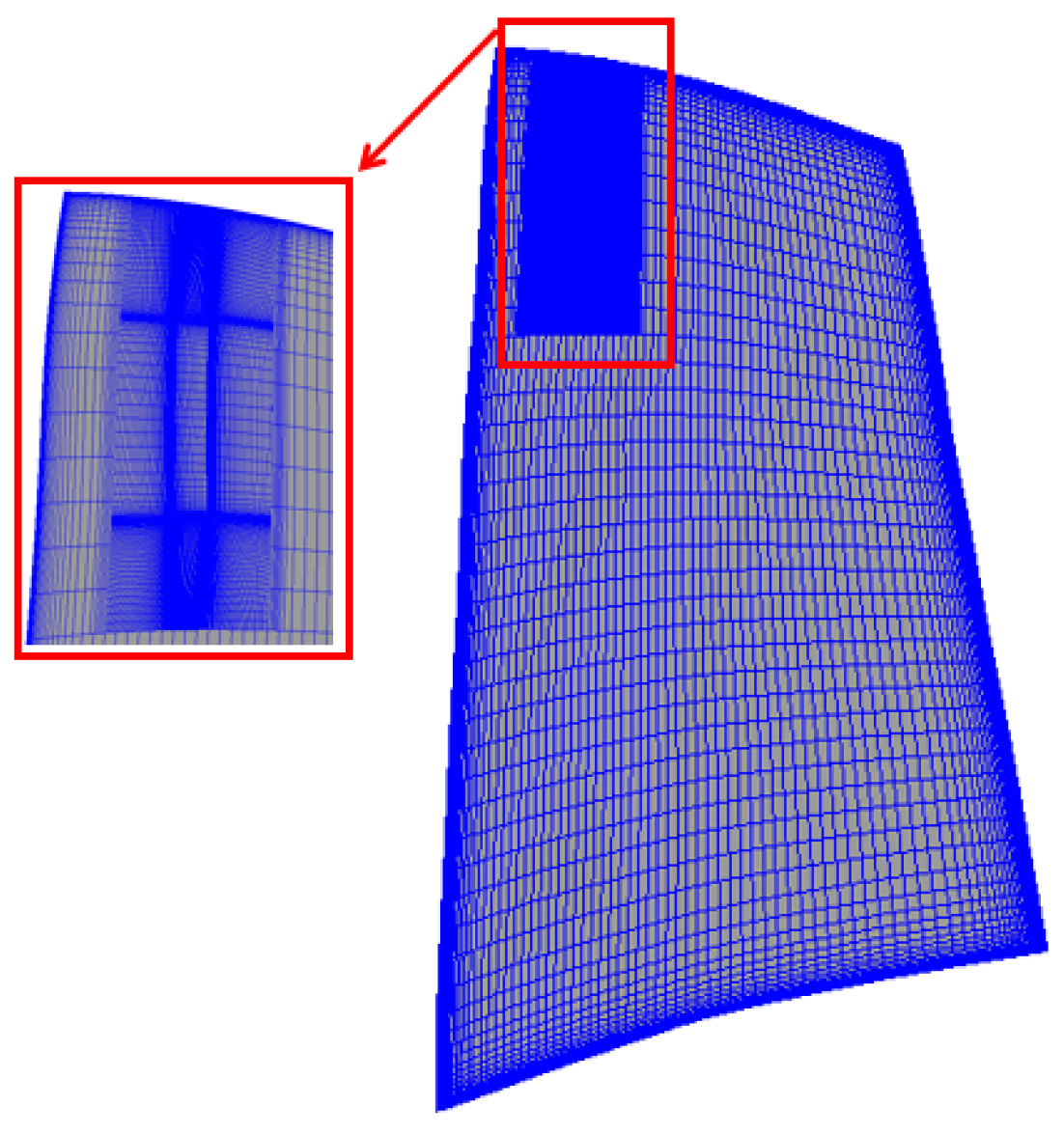
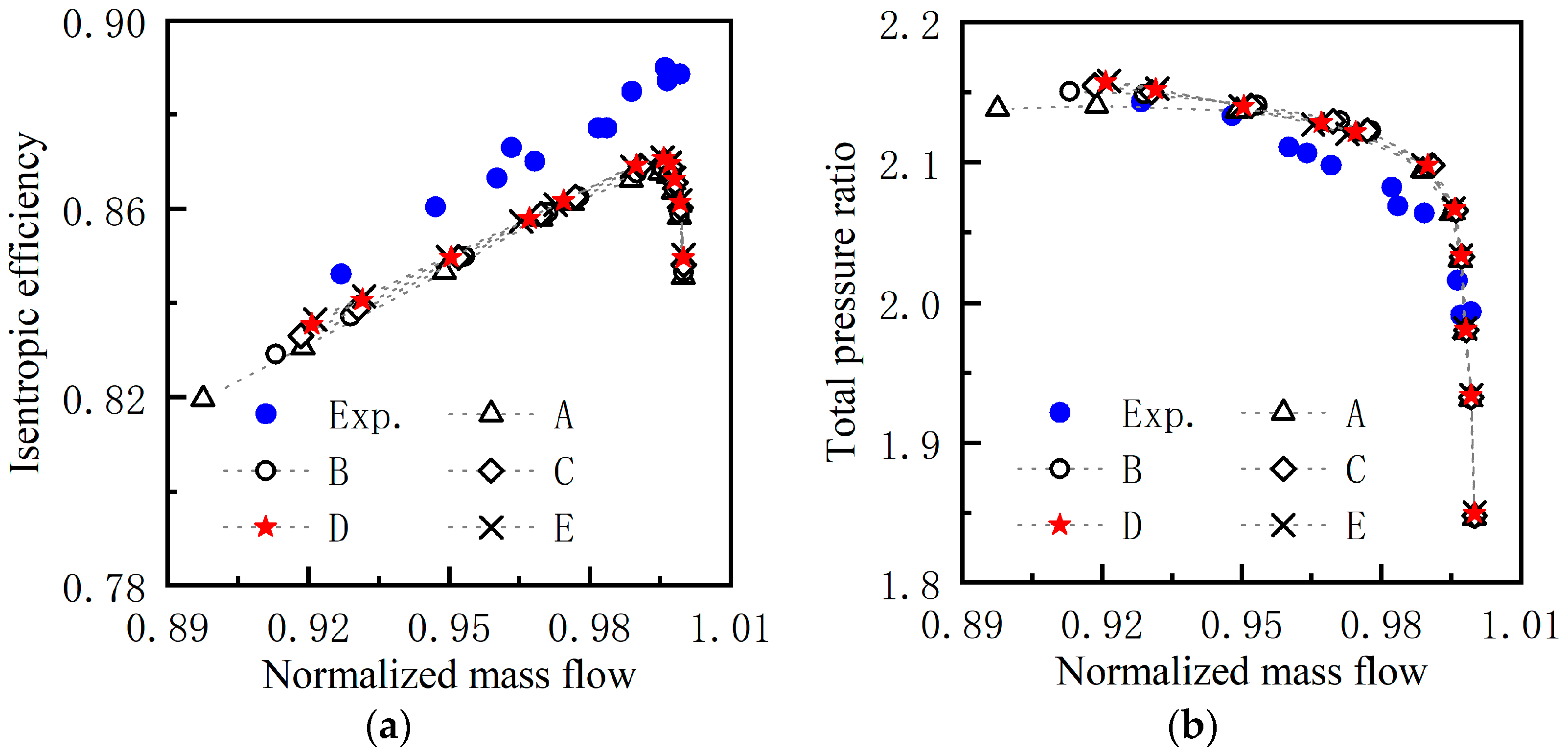
Rotor37, as shown in Figure 1, designed by NASA (Washington, DC, USA) in the 1970s, is among four high-pressure compressor types, characterized by its typical geometry and performance parameters for transonic compressor rotors. NASA has published detailed test data from rotor tests, which serve to validate the accuracy of the numerical simulation method introduced in this study. In this paper, a single channel is used for the numerical simulation. Five computational domain discretization schemes (A, B, C, D, and E) are used with the grid numbers of 6.0 × 10⁴, 8.7 × 10⁴, 1.12 × 10⁵, 1.54 × 10⁵, and 1.96 × 10⁵, respectively. The O4H mesh topology is used around the blade, and the H mesh topology is adopted in the slotted area, as shown in Figure 2. The turbulence model is k-ε, and the grid Y + is about 20~30, which meets the requirements of the turbulence model. The total pressure of the inlet is 101,325 Pa, and the total temperature is 288.15 k. The inlet direction is set to be axial, and the outlet is given static pressure according to different working conditions. The solid wall is adiabatic, and the non-slip boundary condition was conducted.
Figure 3 illustrates the comparison between the characteristic line of Rotor37 from numerical calculations and the test results at the design speed. It can be seen that when the number of grids is 1.54 × 10⁵, the rotor total pressure ratio and isentropic efficiency do not change with the number of grids, so the numerical simulation results of scheme D are finally selected for comparative analysis. Scheme D numerical simulation predicts a choke mass flow of 20.88 kg/s compared to the experimental range of 20.93 ± 0.14 kg/s [35]. The numerical calculations yield a maximum efficiency of 0.865 and a total pressure ratio of 2.09, while the test results show a maximum efficiency of 0.876 and a total pressure ratio of 2.056, indicating an efficiency discrepancy of 1.25% and a total pressure ratio variance of 1.6%. It is noteworthy that the numerically calculated pressure ratio slightly surpasses the test-derived value. Furthermore, many CFD researchers report Rotor37’s adiabatic efficiency to be about 2% lower than the experimental findings [36]. In conclusion, the numerical simulation method applied in this study is demonstrated to be both reliable and accurate.
The compression ratio, temperature ratio, and efficiency are calculated as follows:
Total pressure ratio
π = P T o u t P T i n
Temperature ratio
τ = T T o u t T T i n
Isentropic efficiency
η s = ( π k 1 k 1 ) τ 1
Surge margin
S M = ( π s t a l l / m s t a l l π p e a k / m p e a k 1 ) × 100 %
where π is the total pressure ratio; P T i n ,     P T o u t is the total pressure at the inlet and outlet, Pa; τ is the total temperature ratio; T T i n   , T T o u t is the total temperature at the inlet and outlet; η s is the isentropic efficiency; k is the air adiabatic index (k = 1.4); and SM is the surge margin. The subscripts “peak” and “stall” represent the maximum efficiency and near-stall conditions, respectively. m, mass flow, kg/s.

2.2.3. Slotting Scheme

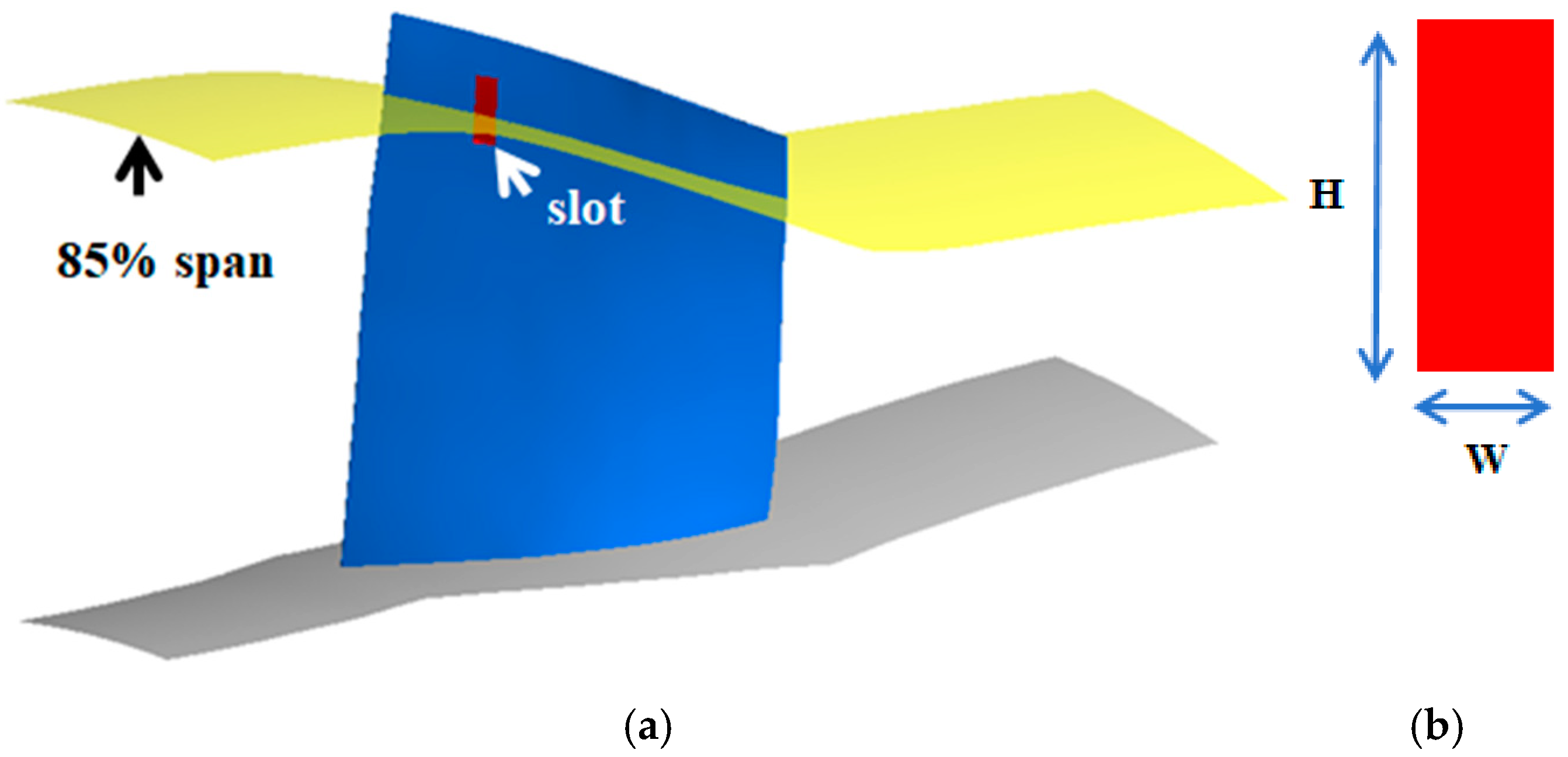
Building on prior research, the optimal slot opening has been identified at 16% of the axial chord length, with the slot extending directly from the pressure surface to the suction surface in a quasi-rectangular cross-section. The central of slots with different slot heights (H) and widths (W) was fixed at the position of 16% axial chord length and a span of 0.85. The aspect ratio ( A r ) was defined as the ratio of the height to the width of the slot.
Aspect ratio
A r = H W
Figure 4 shows the slot design. Compared to the previous work in Ref. [18] and Ref. [25], in order to reduce the influence of slotting on the flow field of the whole blade height, the positions of the shock wave and boundary layer were accurately controlled. Seven kinds of slotting schemes were devised, as shown in Table 2.

3. Results and Discussion

3.1. Total Performance Analysis

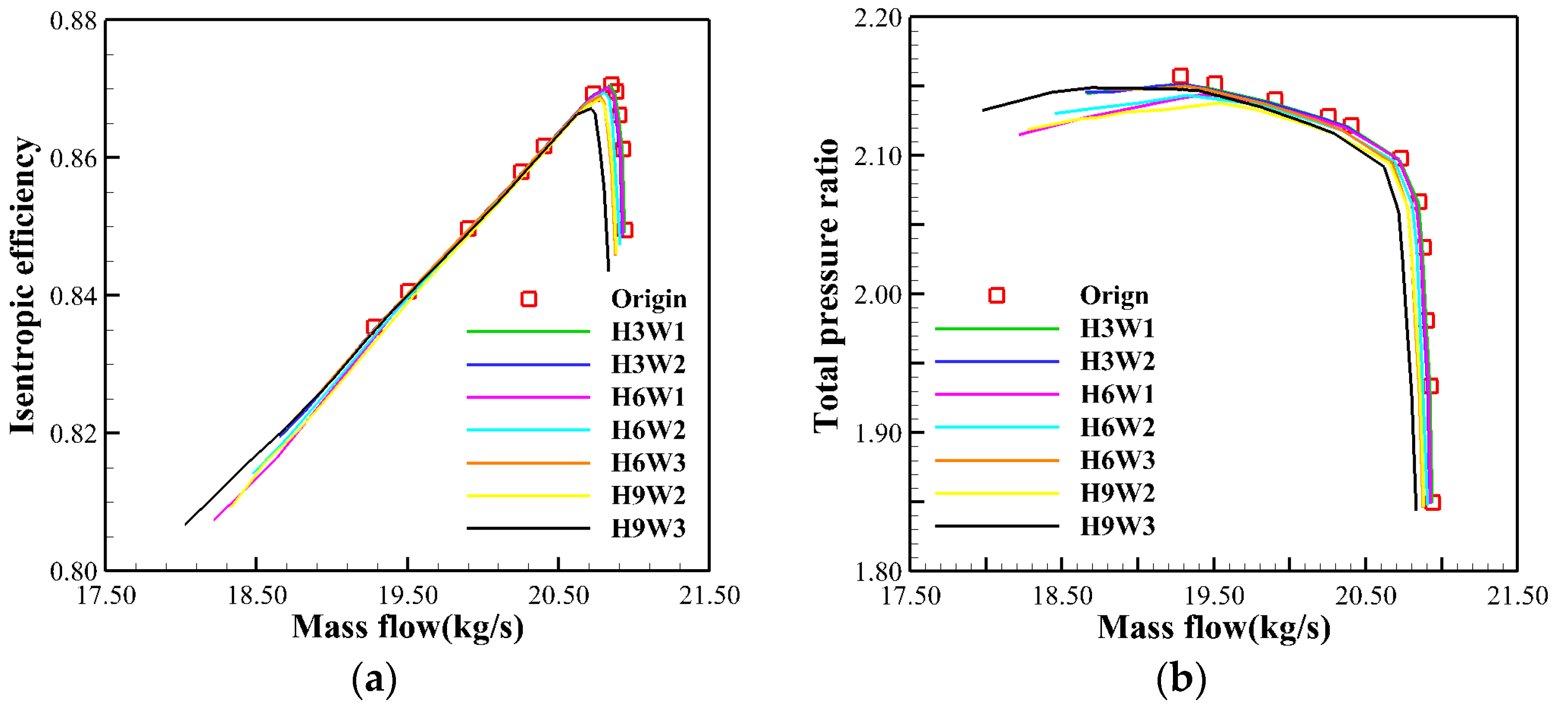
Figure 5 presents the flow–efficiency and flow–pressure ratio curves for both the prototype and the seven slotting schemes. Analysis of these curves reveals that various slotting schemes can extend the compressor’s stable operating range to varying degrees. Notably, the maximum pressure ratio remains nearly constant at 2.15 for all schemes, with the maximum flow rate either unchanged or marginally reduced. A significant reduction was observed in the flow at near-stall conditions. Specifically, scheme H9W3 demonstrates the most pronounced stabilization effect, achieving a near-stall point flow of 18 kg/s. According to Equation (4), the surge margin increased by 60.9% compared with the prototype. The maximum operational flow shows a slight decrease, of approximately 0.5% lower than that of the prototype, and the maximum efficiency is marginally reduced by 0.3%, with the maximum pressure ratio remaining virtually unchanged. Consequently, all seven slotting schemes effectively broaden the stable operating range of the blade, with the corresponding performance losses being minimal when compared to the stabilization benefits.

3.2. Different Slot Width Flow Field Contrast (H = 6 mm)

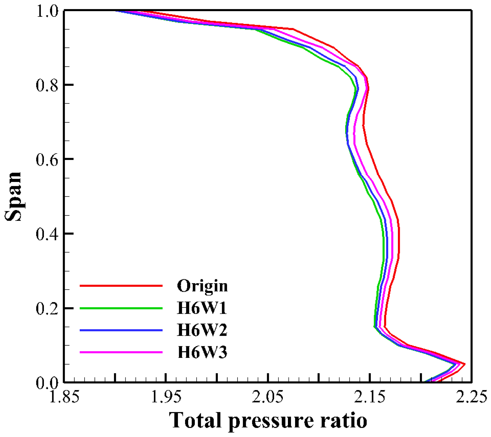
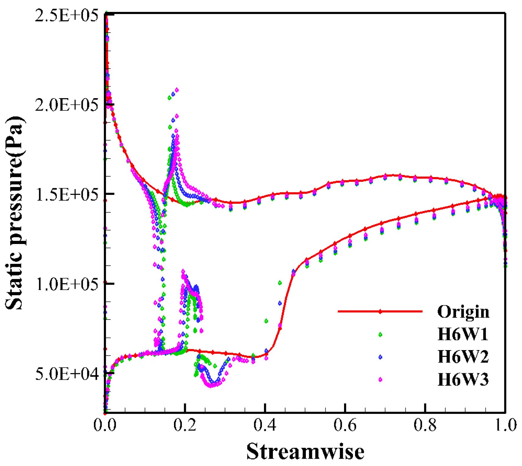
Figure 6 shows the distribution of the outlet spanwise total pressure ratio with the different slot widths (H = 6 mm) under the peak efficiency condition. It can be seen from the figure that, compared with the prototype, the slot design has little effect on the flow field at the hub and shroud, but it has an effect on the region of 10–90% span. As the aspect ratio reduces, the total pressure ratio gradually increases, but it is slightly lower than the prototype total pressure ratio. Compared with Figure 7, the distribution of static pressure on the zone of 85% span, the slotting adjusts the load distribution of the overall blade, especially at the zone of 27% axial chord length. As the aspect ratio decreases, the blade load increases more obviously. The blade load has been slightly increased at the zone of 45–95% chord length. With the decreasing aspect ratio, the load is increased by 16.21%, 12.88%, and 7.53%, respectively. However, from the zone of 85% span in Figure 6, the total pressure ratio of the slotted blade in the direction of the intercept is slightly lower than that of the prototype. This may be due to the interaction between the jet at the slot and the boundary layer on the blade, which leads to the increasing total pressure loss in the flow channel, thus reducing the total pressure ratio of the slotted blade.
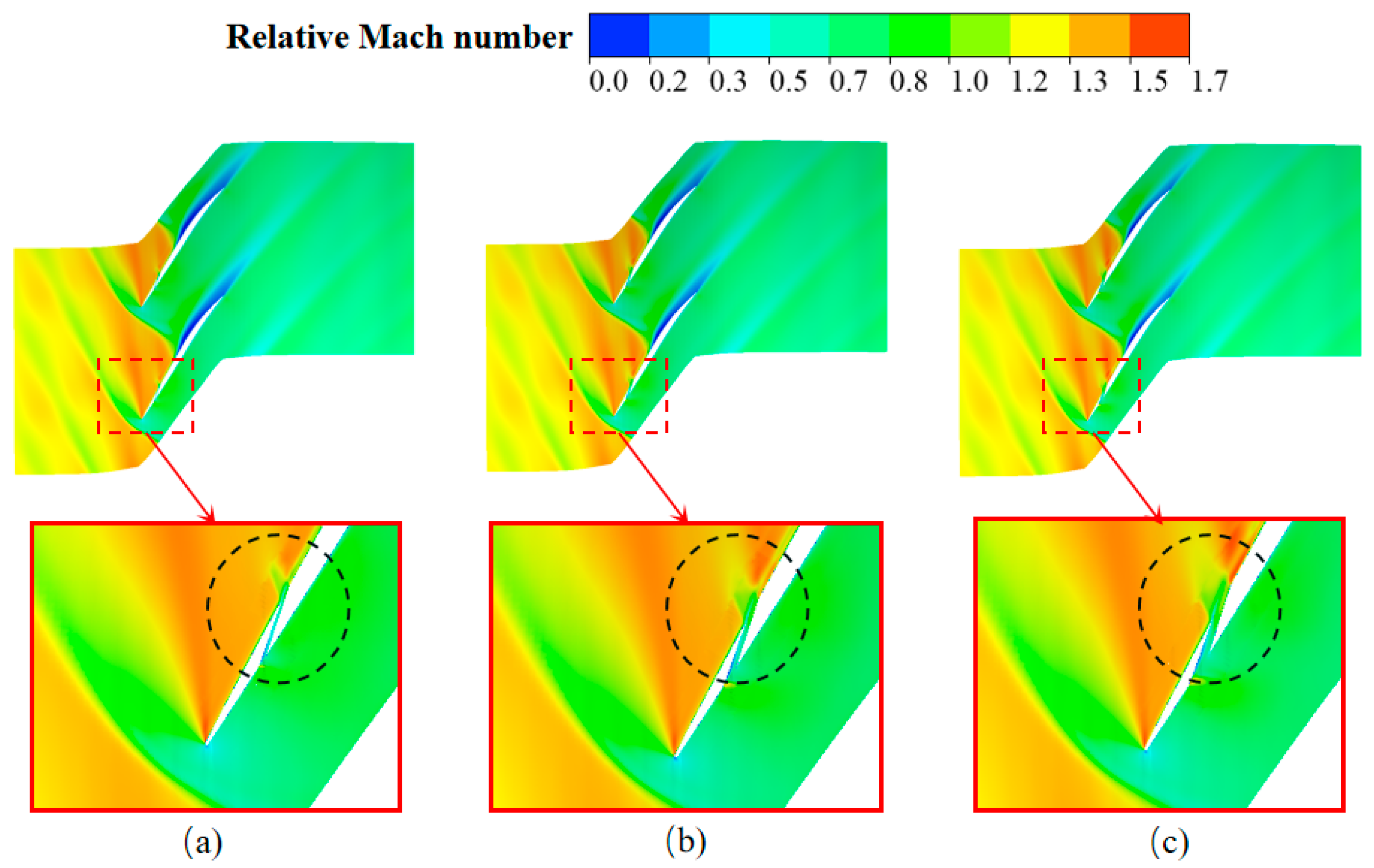
Figure 8 illustrates the distribution of relative Mach numbers on the zone of 85% span with different varying slot widths under the peak efficiency condition. Figure 7 shows the increasing observed pressure integrating at the zone of 27% chord length of the blade; it reveals that fluid flows from the inlet of the slotted pressure surface to the outlet on the suction side. This flow, driven by pressure differences, generates a jet that augments the kinetic energy of the boundary layer on the suction surface, enhancing its resistance to separation. Then, the momentum supplementation was conducted for the low-energy fluid on the suction surface behind the shock wave, which excited a secondary acceleration. This process may even generate a secondary shock wave, thereby elevating the post-wave fluid pressure. However, the increasing loss is due to an elevated total pressure loss by the shock wave, resulting in a slightly reduced total pressure ratio for the slotted blade compared to the prototype’s blade.
Nevertheless, as the slot width increases, the boundary layer thickness post-shock wave gradually diminishes, facilitating fluid through the flow channel and mitigating channel blockage. This approach broadens the operational range. Concurrently, due to the abrupt increase in the flow channel width and the decreasing reverse pressure gradient on the initiation point of the jet slot on the pressure surface, the flow has been accelerated within a limited range, creating a weak shock wave, and then the post-wave fluid was decelerated. A boundary layer also forms within the jet slot, impeding the jet’s velocity.
With the widening of the jet gap, the degree of blockage is marginally reduced. A comparison with Figure 6 reveals that scheme H9W3 shows the highest total pressure at the blade outlet and the greatest blade load. This finding confirms that the interaction between the jet in the slot and the blade surface’s boundary layer, as mentioned above, contributes to the increased total pressure loss at the slot and a reduced mean total pressure ratio.

3.3. Different Slot Height Flow Field Contrast (W = 2 mm)

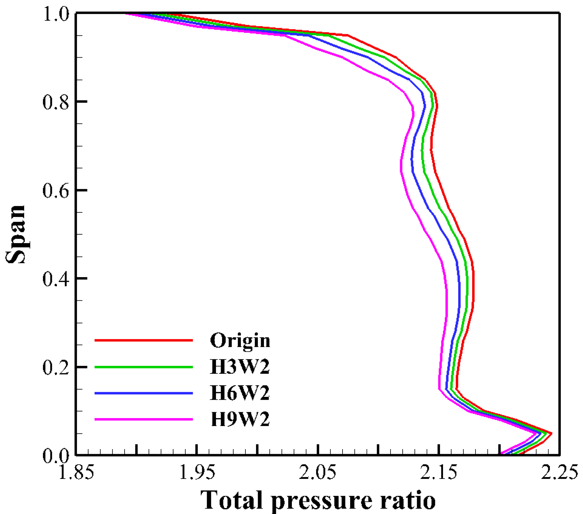
Figure 9 presents the spanwise distribution of the outlet total pressure ratio with the different slot heights (W = 2 mm) under the peak efficiency condition. It illustrates that, with a constant slot width, the total pressure ratio diminishes progressively as the slot height increases, indicating a reduction in total pressure recovery capability. Compared to the static pressure distribution with the 85% span of the blade surface (W = 2 mm) and different slot heights, as shown in Figure 10, the increasing slot height leads to a decreasing load on the first half of the blade and an increasing load on the second half.
As the slot height increases, the maximum load increases from 58% to 95%, corresponding with the chord length of 12.65%, 15.92%, and 23.51%, respectively. The load distribution is more uniform across the entire blade due to the slotting. As the slot height increases, the load distribution across the entire blade shifts rearward.
Figure 11 shows the distribution of relative Mach numbers across an 85% span (W = 2 mm) with different slot heights under the peak efficiency condition. When the slot width remains constant, the jet slot’s impact on the blade is as same as the principle in Figure 7.
Due to the pressure difference between the pressure and suction sides, the airflow expelled from the slot displaces the decelerated fluid near the suction side; consequently, the boundary layer separation weakens. As the slot height increases, the efficacy of the airflow ejected from the slot diminishes, resulting in a gradual thickening of the boundary layer behind the shock wave within the flow channel.

3.4. Comparison of Flow Fields with the Same Slot Area and Different Slot Shapes

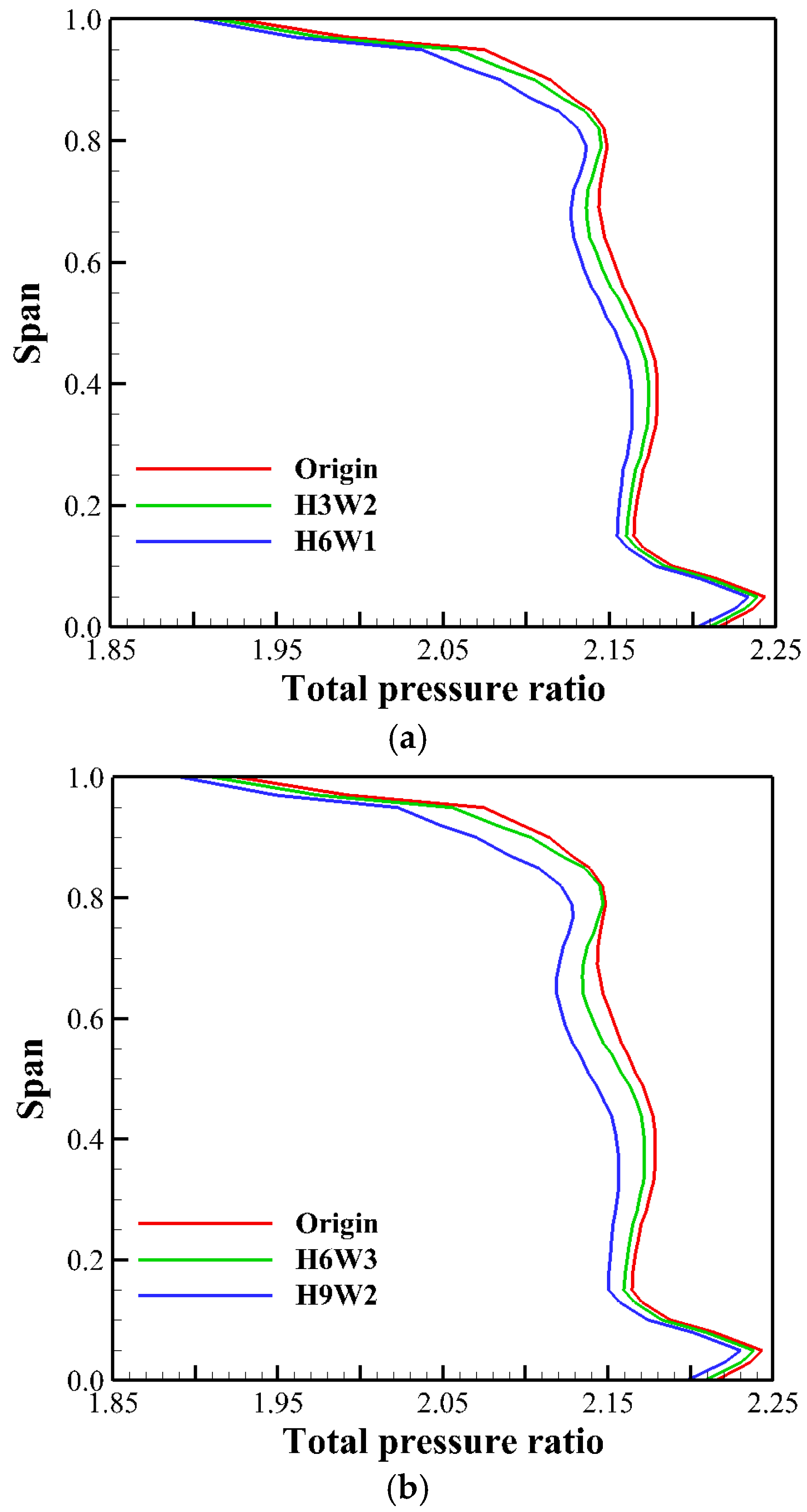
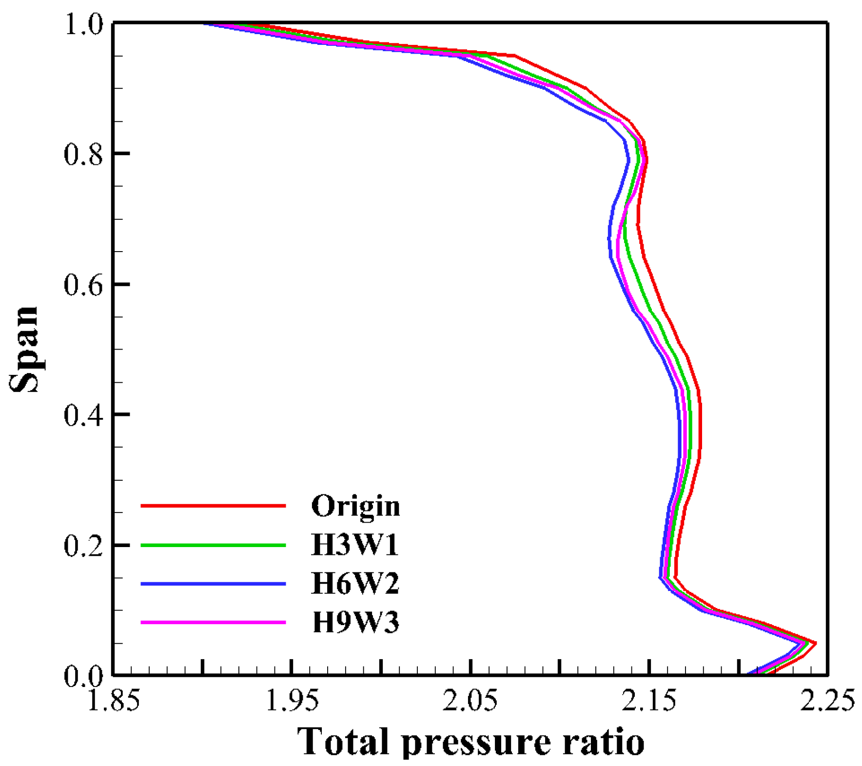
Figure 12 shows the spanwise distribution of the outlet total pressure ratio with the identical slot areas and different slot shapes under the peak efficiency condition. It illustrates that the slot design results in a decreased outlet total pressure across the 10–90% span, and the slender slotting approach has a greater effect than the square slitting method.
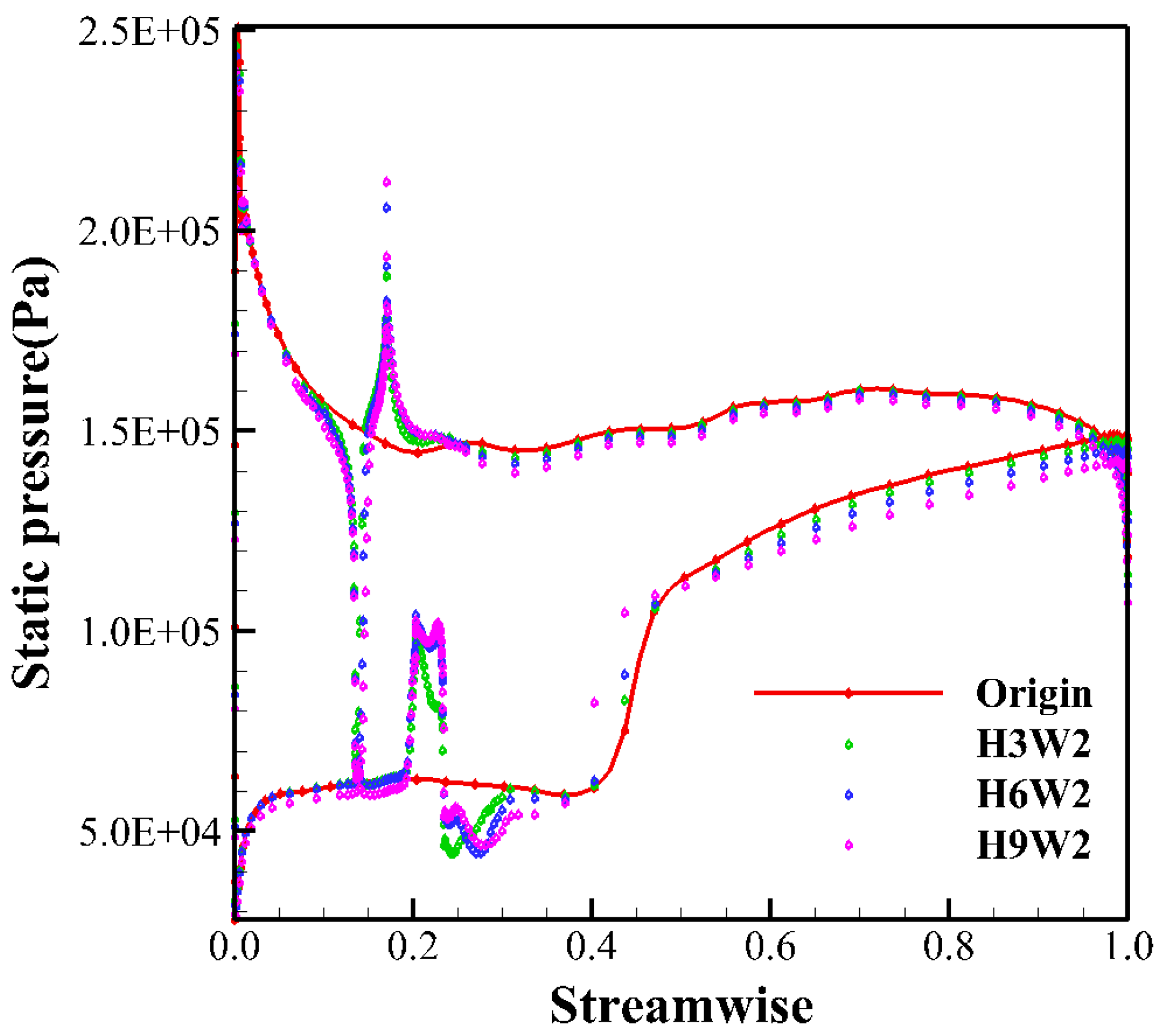
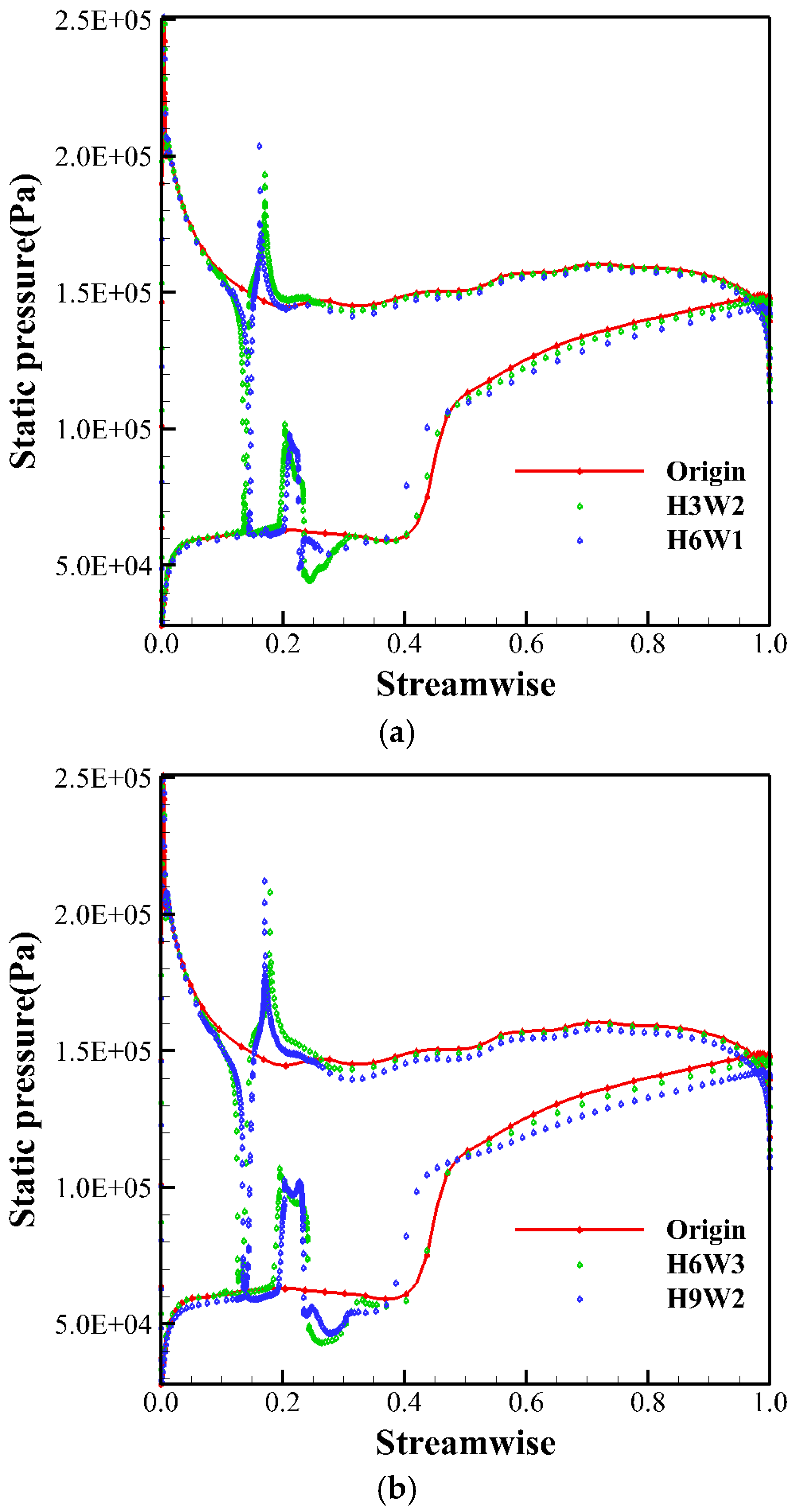
A comparison of the static pressure distribution on the blade surface at an 85% span with identical slot areas under the peak efficiency condition was conducted, as shown in Figure 13. It reveals that slots with the same area have minimal effect on the load on the leading edge blade (20% span). However, the load of the latter blade is improved, and the load is reducing on the position of 20–50% chord length. The slotting results in a slight increase in load at the 27% chord length on the suction surface, and the above influence is more obvious by the square slotting corresponding to the slender slotting.
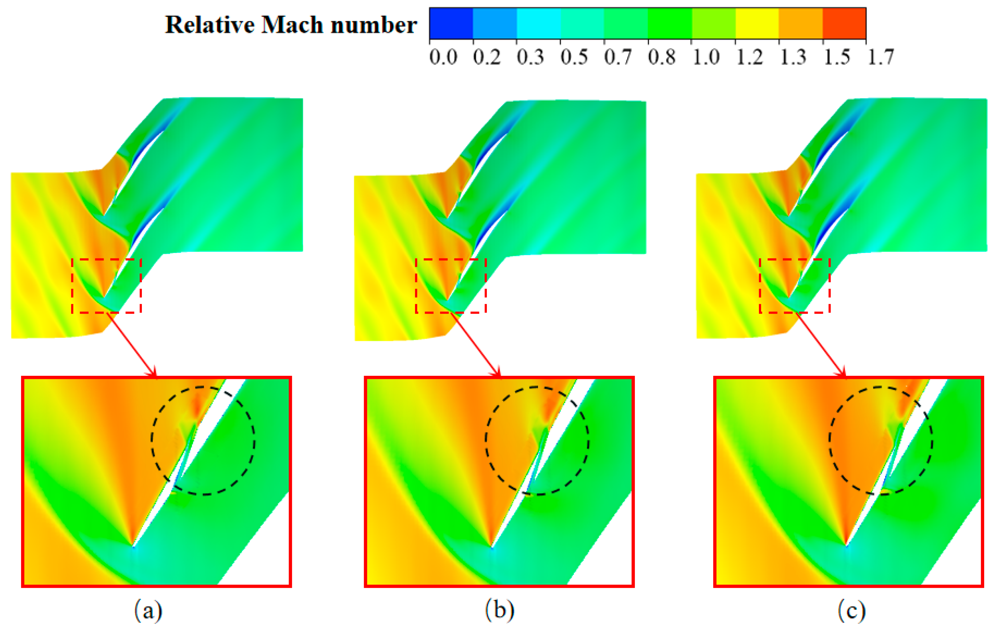
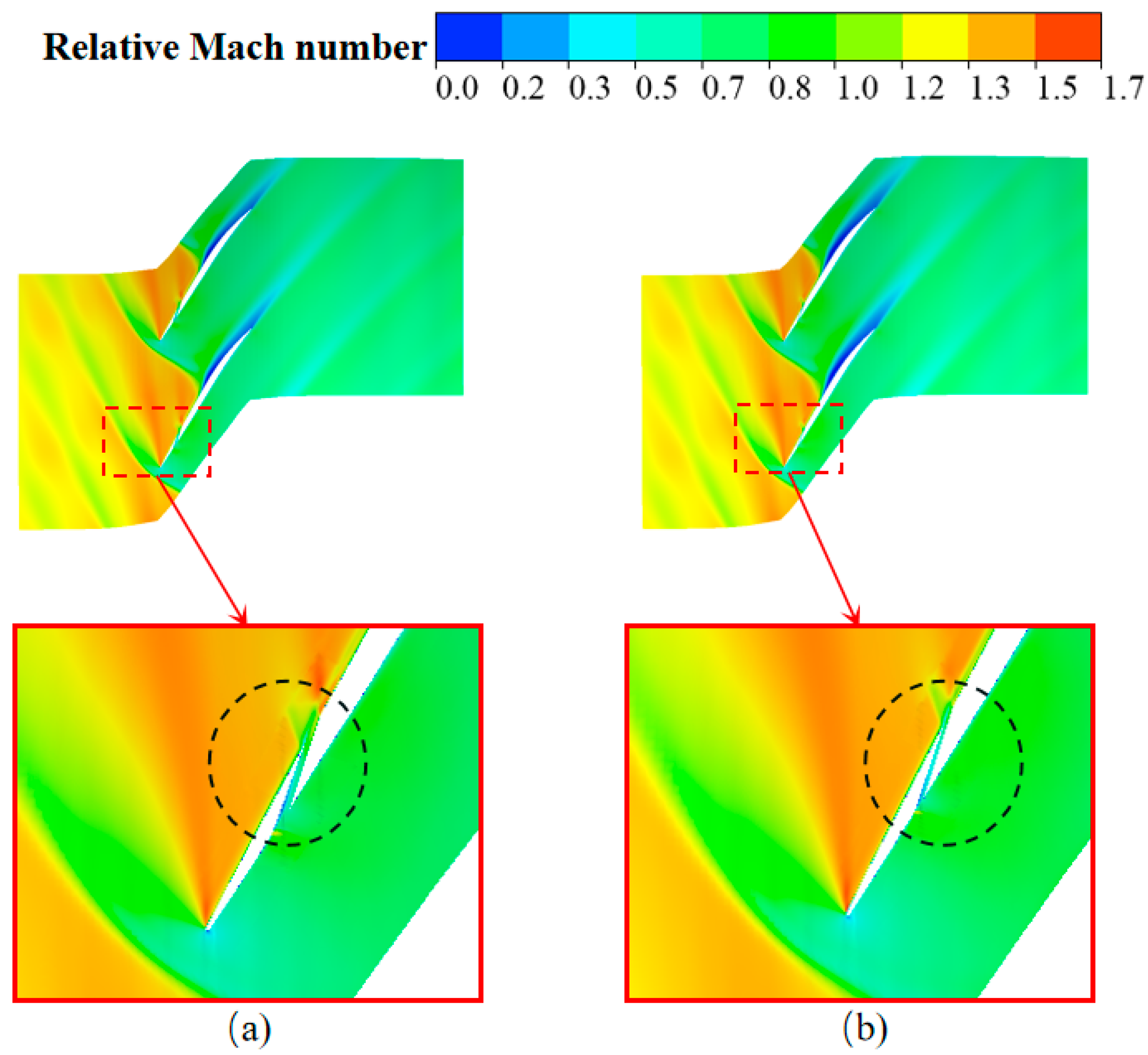
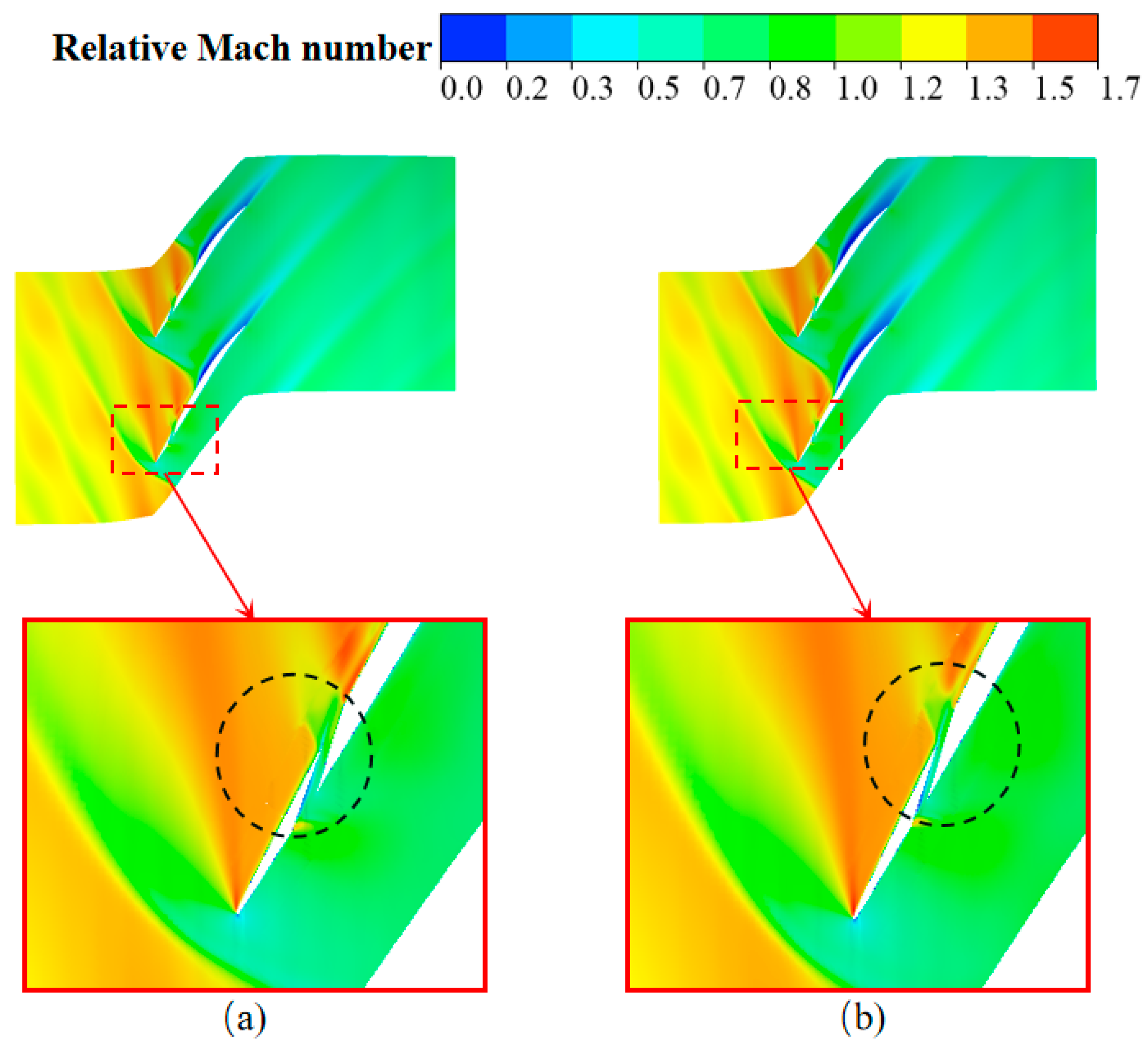
Figure 14 and Figure 15 show the distribution of relative Mach numbers at an 85% span with identical slot areas under the peak efficiency condition. It indicates that, for an identical slot area, the boundary layer behind the shock wave is thicker for the slender slot than that for the square slot. A larger slot area corresponds to a more pronounced thickening of the boundary layer. Increasing the slot area results in accelerated flow at the slot’s beginning due to jet acceleration. From the gradient of relative Mach number change, it can be seen that the shock wave on the leading edge of the blade is weaker than that on the pressure surface of the slot’s entrance, increasing the fluid loss.

3.5. Comparison in Different Slot Areas with the Same Aspect Ratio

Figure 16 illustrates the spanwise distribution of the total pressure ratio varying slot areas with a constant aspect ratio under the peak efficiency condition. It reveals that, compared with the prototype, the slot design minimally impacts the flow field at the hub and shroud, while obviously affecting the flow field on the position of 10–90% span. Additionally, as the slot area increases, there is a gradual decrease in the total pressure ratio. Compared with the static pressure distribution on the 85% span with the same aspect ratio and different slot areas, as shown in Figure 17, it indicates that the slot design minimally impacts the load on the second half of the blade. As the slot area increases, the load on the first half of the blade shifts rearward, and, concurrently, there is a slight increase in the overall blade load.
Figure 18 shows the distribution of relative Mach numbers at 85% span varying slot areas with the same aspect ratio under the peak efficiency condition. As the slot area increases, the jet acceleration at the initial position of the slot pressure surface induces a weak shock wave at the inlet, thereby exacerbating the flow loss. It confirms that the total pressure loss associated with the large-area slotting method exceeds that of the small-area slotting method. However, the larger slot area facilitates jet energy supplementation to the fluid at the slot’s outlet. This supplementation is helpful to expel the low-energy fluid on the suction surface, diminishing the interaction between the shock wave and the boundary layer, thereby mitigating channel blockage and enhancing the compressor’s surge margin.

3.6. Discussion and Summary

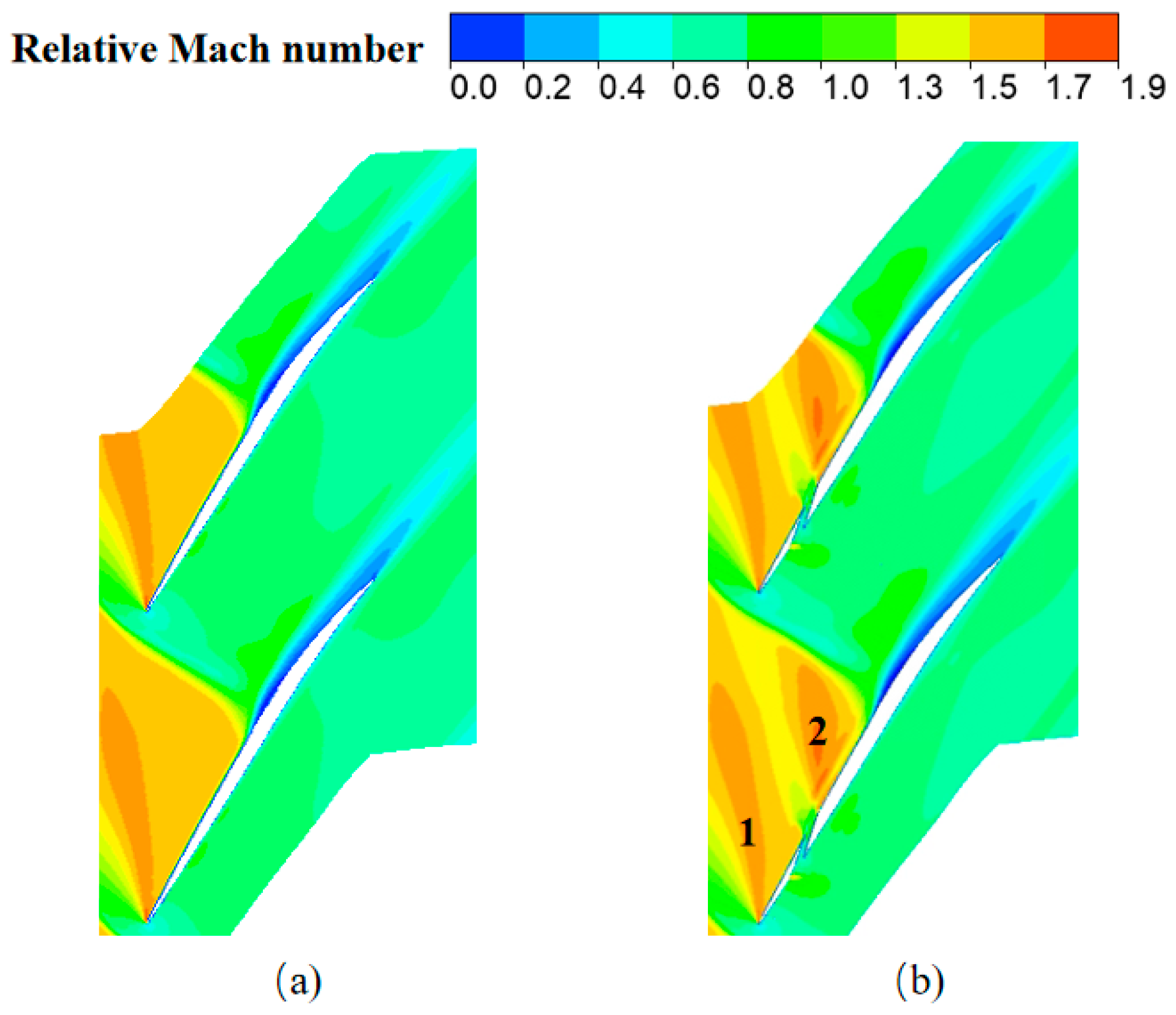
Figure 19 shows the distribution of relative Mach numbers at an 85% span under the near-stall condition for the prototype and H9W3. Under near-stall conditions, due to the higher outlet pressure, a shock wave forms at the leading edge of the prototype rotor blade, and the shock wave affects almost the entire flow channel. The strong adverse pressure gradient hinders the fluid downstream flow. The shock wave is composed of “1” and “2” parts on the leading edge of the slotted rotor (H9W3), which reduces the reverse pressure gradient at the shock wave and weakens the obstruction of the shock wave to the downstream flow of the fluid. Compared with the prototype, the flow capacity of the slotted rotor is enhanced under this flow condition, and there is a certain stable working margin from the stall.
Compared to the chord-wise slotting method (the slotting penetrates the front and rear edges of the blade) and the longitudinal slotting method (the slotting extends from the hub to the shroud) by other researchers, the slotting method proposed in this paper is both simpler and more effective. In transonic compressors, particularly at the blade tip, blades are often designed to be thin and bear high loads. A too extensive slotting range or a complex slotting method not only requires high machining precision and poses difficulties but may also compromise the blade’s structural integrity, increasing the risk of blade fracture under near-stall conditions. Hu et al. designed the Rotor37 blade tip by slotting, which increased the stall margin of the compressor by 2.33–4.53% and reduced the peak efficiency by 0.26–1.24% [37]. The reason for the stability expansion of this scheme is the suction effect of the channel inlet on the low-speed flow at the pressure front edge, the blowing effect of the outlet jet on the trailing edge separation on the suction surface, and the reduction in the leakage in the tip clearance. In this paper, the slot is located at 85% span of the blade and 16% axial chord length. For the slotted scheme H9W3, compared with the prototype, the stall margin of the compressor is increased by 60.9%, and the peak efficiency is reduced by 0.3%. The stability expansion effect is better than Hu’s scheme. This study demonstrates that an adaptive jet, an opening and penetrating slot with a limited area from the pressure to the suction surface at the blade’s top, can control the flow field parameters within the region. This approach effectively expands the stability range with minimal impact on the pressure ratio and efficiency. Overall, the benefits of this slotting method outweigh its drawbacks.

4. Conclusions and Discussion

This research demonstrates that the slotting technique effectively controls flow separation. High-energy fluid, through the slot from the pressure to the suction surface, forms a jet at the outlet. This jet injects energy into the low-energy fluid on the suction surface, thereby effectively controlling blade surface flow separation and alleviating channel blockage.
(1)
There is an optimal slot position and size. The stability expansion effect of the Ar = 3.0 (H9W3) scheme is the most obvious, and the surge margin is 60.9% higher than that of the prototype. The maximum working flow is reduced by about 0.5% compared with the prototype. The maximum efficiency decreases by about 0.3%, and the maximum pressure ratio remains almost unchanged.
(2)
As the slot width increases while maintaining the same slot height, there is a gradual increase in the outlet’s total pressure ratio. The slot design modifies the blade’s overall load distribution, particularly at 27% of the axial chord length, where an increase in slot width results in a more pronounced increase in blade load. Additionally, the slotted blade design has slightly enhanced the load on the entire back half of the blade.
(3)
With a constant slot width, an increase in the slot height leads to a gradual decrease in the total pressure ratio, a slight rearward shift in the blade load, diminished impact force of the airflow ejected from the slot, and a gradual thickening of the boundary layer behind the shock wave within the flow channel.
(4)
For identical slot areas but varying shapes, the total pressure ratio associated with slender slots exceeds that of square slots. Square slots outperform slender slots in controlling flow separation. Slot designs of identical areas minimally impact the load on the blade’s initial 20% axial chord, yet they enhance the load on the latter half and decrease the load between the 20 and 50% axial chord. The slotting approach marginally elevates the load at the 27% axial chord on the suction surface, with the increase being more pronounced for square slots than for slender ones. The boundary layer behind the shock wave is thicker for slender slots than for square slots. Additionally, an increase in the slot area correlates with more significant thickening of the boundary layer.
(5)
As the opening area increases, maintaining the same aspect ratio, the total pressure ratio correspondingly decreases. The slot design minimally impacts the load in the latter half of the blade. With an enlarged slot area, the load on the first half of the blade shifts rearward, and there is a slight increase in the overall blade load.

Author Contributions

Conceptualization, Y.G. and X.L.; investigation, X.L. and J.Z.; writing—original draft preparation, Y.G.; writing—review and editing, Y.G. All authors have read and agreed to the published version of the manuscript.

Funding

The present work is supported financially by the Key Program of the National Natural Science Foundation of China (52236005), the Liaoning Province Science and Technology Program Foundation (open bidding for selecting the best candidates, 2023JH1/10400050), the Science and Technology Joint Plan Project of Liaoning Province (2023JH2/101700256), the Superior College Science and Technology Research Project of Liaoning Province (LJKZZ20220138), and the Basic Scientific Research Projects for Colleges and Universities under the Education Department of Liaoning Province (LJ242411632005, LJ242411632018, LJ242411632102, LIKZZ20220138).

Data Availability Statement

The original contributions presented in the study are included in the article material, further inquiries can be directed to the corresponding author.

Conflicts of Interest

The authors declare no conflict of interest.

Nomenclature

Hslot width (mm)
kadiabatic exponent
mmass flow rate (kg/s)
Wslot height (mm)
PTtotal pressure(pa)
TTtotal temperature (k)
ηsIsentropic efficiency
πtotal pressure ratio
τtotal temperature ratio
Subscripts
incompressor inlet
outcompressor outlet
peakpeak efficiency working condition
stallnear-stall working condition
Abbreviations
CFDComputational fluid dynamics
DBDDielectric Barrier Discharge
SMSurge Margin

References

  1. Eckel, J.; Von, J.P.; Guemmer, V. Numerical Investigation of Near-Tip Modifications for a Highly Loaded Low-Speed Rotor under the Influence of Double Leakage. J. Turbomach. 2023, 145, 041003. [Google Scholar] [CrossRef]
  2. Wang, M.; Lu, X.; Yang, C.; Zhao, S.; Zhang, Y. Control of Separated Flow Transition over a Highly Loaded Compressor Blade via Dynamic Surface Deformation. Int. J. Mech. Sci. 2023, 241, 107980. [Google Scholar] [CrossRef]
  3. Ding, S.; Chen, S.; Hao, S.; Wang, S. Flow Instability Control of an Ultra-highly Loaded Transonic Compressor Rotor Using Self-excited Casing Bleed. Phys. Fluids 2023, 35, 066134. [Google Scholar]
  4. Guan, D.; Liu, Y.; Zhao, D.; Du, J.; Dong, X.; Sun, D. Experimental Mode Decomposition Investigation on 3-stage Axial Flow Compressor Stall Phenomena Using Aeroacoustics Measurements. Aerosp. Sci. Technol. 2023, 139, 108386. [Google Scholar] [CrossRef]
  5. Sun, D.; Nie, C.; Liu, X.; Lin, F.; Sun, X. Further investigation on transonic compressor stall margin enhancement with stall precursor-suppressed casing treatment. J. Turbomach. 2016, 138, 021001. [Google Scholar] [CrossRef]
  6. Zhong, X.-Y.; Huang, W.; Yan, L.; Wu, H.; Du, Z.-B. Investigation on the Adaptive Control of Shock Wave/turbulent Boundary Layer Interaction Based on the Secondary Circulation Jets. Acta Astronaut. 2022, 198, 233–250. [Google Scholar] [CrossRef]
  7. De Vincentiis, L.; Ðurović, K.; Lengani, D.; Simoni, D.; Pralits, J.; Henningson, D.S.; Hanifi, A. Effects of Upstream Wakes on the Boundary Layer over a Low-Pressure Turbine Blade. J. Turbomach. 2023, 145, 051011. [Google Scholar] [CrossRef]
  8. Liu, L.; Li, J.; Nan, X.; Lin, F. The stall inceptions in an axial compressor with single circumferential groove casing treatment at different axial locations. Aerosp. Sci. Technol. 2016, 59, 145–154. [Google Scholar] [CrossRef]
  9. Zou, K.K.; Liu, Y.B.; Yu, Y.H.; He, X. Effects of Sloped Trench Casing Treatment Combined with Air Injection on Aerodynamic Performance of a 1.5 Stage Axial Flow Compressor. J. Phys. Conf. Ser. 2021, 1888, 012007. [Google Scholar]
  10. Li, K.; Meng, F.; Wang, K.; Guo, P.; Li, J. Performance-Driven Multi-Objective Optimization Method for DLR Transonic Tandem Cascade Shape Design. J. Therm. Sci. 2023, 32, 297–309. [Google Scholar] [CrossRef]
  11. Zhao, Q.; Cui, W.; Xiang, X.; Xu, Q.; Xu, J. Numerical Investigation of Blade Tip Winglet on Flow Structure in a High Loading Transonic Rotor. Proc. Inst. Mech. Eng. Part G J. Aerosp. Eng. 2022, 236, 96–108. [Google Scholar] [CrossRef]
  12. Wanyang, W.U.; Jingjun, Z. Variable Clearance Characteristics of High Subsonic Compressor Cascades with Blade Tip Winglets. J. Therm. Sci. 2022, 31, 16. [Google Scholar]
  13. Veerakumar, R.; Raul, V.; Liu, Y.; Wang, X.; Leifsson, L.; Hu, H. Meta Modeling-based Parametric Optimization of DBD Plasma Actuation to Suppress Flow Separation over a Wind Turbine Airfoil Model. Acta Mech. Sin. 2020, 36, 15. [Google Scholar] [CrossRef]
  14. Siemann, J.; Krenz, I.; Seume, J.R. Experimental Investigation of Aspiration in a Multi-stage High-speed Axial-compressor. Turbo Expo: Power for Land, Sea, and Air. Am. Soc. Mech. Eng. 2016, 49699, V02AT37A010. [Google Scholar]
  15. Gbadebo, S.A.; Cumpsty, N.A.; Hynes, T.P. Control of Three-Dimensional Separations in Axial Compressors by Tailored Boundary Layer Suction. ASME J. Turbomach. 2008, 130, 011004. [Google Scholar] [CrossRef]
  16. Manjunath, L.; Nilugal, K.; Karanth, V.; Madhwesh, N. Numerical Investigations on the Effect of Volute Casing Treatment for Performance Augmentation in a Centrifugal Fan. Proc. Inst. Mech. Eng. Part C J. Mech. Eng. Sci. 2022, 236, 2791–2802. [Google Scholar]
  17. Gholam, H.M.; Ali, R.D.; Mohammad, R.S. Experimental Investigation of the Effect of Active Flow Control on the Wake of a Wind Turbine Blade. Proc. Inst. Mech. Eng. Part C J. Mech. Eng. Sci. 2021, 235, 6122–6138. [Google Scholar]
  18. Gao, T.Y.; Zhang, G.C.; Xu, Z.H.; Liu, P.C. Mechanism of Effects of Rotor Blade Tip Jet Slot on Performance and Flow Structure of Transonic Axial Compressor. J. Propuls. Technol. 2022, 43, 154–162. [Google Scholar]
  19. Wennerstrom, A. Some Experiments with a Supersonic Axial Compressor Stage. J. Turbomach. 1987, 109, 388–397. [Google Scholar] [CrossRef]
  20. Ramzi, M.; Adberrahmane, G. Passive Control Via Slotted Blading in a Compressor Cascade at Stall Condition. J. Appl. Fluid Mech. 2013, 6, 571–580. [Google Scholar]
  21. Tang, Y.M.; Liu, Y.W.; Lu, L.P. Experimental Investigation of the Blade End Slots on Controlling the Corner Seperation in a Highly Loaded Compressor Cascade. J. Eng. Thermophys. 2020, 41, 845–850. [Google Scholar]
  22. Zhang, H.G.; Liu, W.H.; Chu, W.L.; Wang, E. The Effect of Radial Skew Angles of Blade Angle Slots on the Stability and Performance of an Axial Flow Compressor. Turbo Expo: Power for Land, Sea, and Air. Am. Soc. Mech. Eng. 2020, 84065, V02AT32A021. [Google Scholar]
  23. Pieruszka, A.; Siwek, T.; Kalawa, W.; Lis, Ł.; Stefański, S.; Sztekler, K. The Effect of Blade Slots on Flow Behaviour in a Fan Impeller. Eur. Phys. J. Conf. 2019, 213, 02067. [Google Scholar] [CrossRef]
  24. Zhu, M.; Qiang, X.; Yu, W.; Teng, J. Analysis on Slot-type Casing Treatment Injection Flow in an Axial Transonic Compressor. Proc. Inst. Mech. Eng. 2016, 230, 792–804. [Google Scholar] [CrossRef]
  25. Li, X.D.; Sun, P.; Fu, W.G. Mechanism of Top Slot Affecting Stability of Transonic Compressor Rotor. J. Propuls. Technol. 2022, 43, 105–114. [Google Scholar]
  26. Jung, Y.J.; Jeon, H.; Jung, Y.; Lee, K.J.; Choi, M. Effects of recessed blade tips on stall margin in a transonic axial compressor. Aerosp. Sci. Technol. 2016, 54, 41–48. [Google Scholar] [CrossRef]
  27. Malhotra, A.; Goswami, S.; Madathil, P.A. Performance Deterioration of Axial Compressor Rotor Due to Uniform and Non-uniform Surface Roughness. Proc. Inst. Mech. Eng. Part G J. Aerosp. Eng. 2022, 236, 2687–2707. [Google Scholar] [CrossRef]
  28. Yao, Y.; Zhang, J.Z.; Wang, L.P. Film Cooling on a Gas Turbine Blade Suction Side with Converging Slot-hole. Int. J. Therm. Sci. 2013, 65, 267–279. [Google Scholar] [CrossRef]
  29. Ni, Z.; Dhanak, M.; Su, T.C. Improved Performance of a Slotted Blade Using a Novel Slot Design. J. Wind Eng. Ind. Aerodyn. 2019, 189, 34–44. [Google Scholar] [CrossRef]
  30. Mousavi, S.M.; Ghadimi, B.; Kowsary, F. Numerical Study on the Effects of Multiple Inlet Slot Configurations on Swirl Cooling of a Gas Turbine Blade Leading Edge. Int. Commun. Heat Mass Transf. 2018, 90, 34–43. [Google Scholar] [CrossRef]
  31. Zhang, H.; Dong, F.; Wang, E.; Liu, W.; Chu, W. Effect of Different Radial Skewed Angles of Reversed Blade-angle Slot Casing Treatment on Transonic Axial Flow Compressor Stability. Proc. Inst. Mech. Eng. Part G J. Aerosp. Eng. 2022, 236, 1617–1632. [Google Scholar] [CrossRef]
  32. Zhou, X.; Zhao, Q.; Cui, W.; Xu, J. Investigation on Axial Effect of Slot Casing Treatment in a Transonic Compressor. Appl. Therm. Eng. 2017, 126, 53–69. [Google Scholar] [CrossRef]
  33. Wang, L.; Mao, X.; Gao, L.; Guo, Y.; Yu, Y. Effect of Axial Slot Casing Treatment on the Flow Instability for Different Speed Ratios in a Counter-rotating Axial Flow Compressor. Aerosp. Sci. Technol. 2023, 139, 108374. [Google Scholar] [CrossRef]
  34. Suder, K.L. Experimental Investigation of the Flow Field in a Transonic, Axial Flow Compressor with Respect to the Development of Blockage and Loss; Case Western Reserve University: Cleveland, OH, USA, 1996. [Google Scholar]
  35. Dunham, J. CFD Validation for Propulsion System Components; Advisory Group for Aerospace Research and Development Neuilly-Sur-Seine; AGARD, North Atlantic Treaty Organization: Neuilly sur Seine, France, 1998. [Google Scholar]
  36. Feng, F.; Hao, Z.R.; Gu, C.W. Discontinuous Galerkin Method for Simulation of Flowfield in a Transonic Compressor Rotor. J. Eng. Thermophys. 2012, 33, 39–42. [Google Scholar]
  37. Hu, J.G.; Wang, R.G.; Li, K. Investigation on Slot Jetting Flow Method and Mechanism of Transonic Compressor. J. Propuls. Technol. 2014, 35, 1475–1481. [Google Scholar]
Figure 1. Research object (Rotor37).
Aerospace 11 00825 g001
Figure 2. Grid discretization method of the blade.
Aerospace 11 00825 g002
Figure 3. Numerical and experimental comparison of Rotor37. (a) Flow–efficiency characteristic curves. (b) Flow–pressure ratio characteristic curves.
Aerospace 11 00825 g003
Figure 4. Slotted scheme. (a) Slotted blade. (b) Slotting size.
Aerospace 11 00825 g004
Figure 5. Comparison of performance curves. (a) Flow–efficiency characteristic curves. (b) Flow–pressure ratio characteristic curves.
Aerospace 11 00825 g005
Figure 6. Spanwise total pressure ratio distribution of the outlet at different slot widths (H = 6 mm).
Aerospace 11 00825 g006
Figure 7. Static pressure distribution of blade surface at different slot widths (H = 6, span = 0.85).
Aerospace 11 00825 g007
Figure 8. Relative Mach number distribution (H = 6 mm, span = 0.85). (a)H6W1. (b) H6W2. (c) H6W3.
Aerospace 11 00825 g008
Figure 9. Spanwise total pressure ratio distribution of the outlet at different slot heights (W = 2 mm).
Aerospace 11 00825 g009
Figure 10. Static pressure distribution of the blade surface at different slot heights (W = 2 mm, span = 0.85).
Aerospace 11 00825 g010
Figure 11. Relative Mach number distribution (W = 6 mm, span = 0.85). (a) H3W2. (b) H6W2. (c) H9W2.
Aerospace 11 00825 g011
Figure 12. Spanwise total pressure ratio distribution of the outlet with the same slot area. (a) Area = 6. (b) Area = 18.
Aerospace 11 00825 g012
Figure 13. Static pressure distribution of the blade surface with the same slot area. (a) Area = 6. (b) Area = 18.
Aerospace 11 00825 g013
Figure 14. Relative Mach number distribution of 85% span (Area = 6) (a) H3W2. (b) H6W1.
Aerospace 11 00825 g014
Figure 15. Relative Mach number distribution of 85% span (Area = 18). (a) H6W3. (b) H9W2.
Aerospace 11 00825 g015
Figure 16. Spanwise total pressure ratio distribution of the outlet with the same aspect ratio (Ar = 3.0).
Aerospace 11 00825 g016
Figure 17. Static pressure distribution of the blade surface with the same aspect ratio (Ar = 3.0).
Aerospace 11 00825 g017
Figure 18. Relative Mach number distribution of 85% span with the same aspect ratio (Ar = 3.0). (a) H3W1. (b) H6W2. (c) H9W3.
Aerospace 11 00825 g018
Figure 19. Relative Mach number distribution of 85% span with the same mass flow. (a) Prototype. (b) H9W3.
Aerospace 11 00825 g019
Table 1. Rotor37 design parameters [34].
ParameterDesign ValueUnit
Rotor total pressure ratio2.106[-]
Rotor adiabatic efficiency0.877[-]
Mass flow20.188kg/s
Rotor wheel speed17,188.7rpm
Rotor tip speed454.14m/s
Number of rotor blades36[-]
Table 2. Slot scheme.
CaseW = 1 (mm)W = 2 (mm)W = 3 (mm)
H = 3 (mm) A r = 3.0 (H3W1) A r = 1.5 (H3W2)-
H = 6 (mm) A r = 6.0 (H6W1) A r = 3.0 (H6W2) A r = 2.0 (H6W3)
H = 9 (mm)- A r = 4.5 (H9W2) A r = 3.0 (H9W3)
Disclaimer/Publisher’s Note: The statements, opinions and data contained in all publications are solely those of the individual author(s) and contributor(s) and not of MDPI and/or the editor(s). MDPI and/or the editor(s) disclaim responsibility for any injury to people or property resulting from any ideas, methods, instructions or products referred to in the content.