Abstract
Traditional reliability analysis methods such as Reliability Block Diagram, Fault Tree Analysis, and Markov Analysis are all subjective methods whose results significantly depend on the analysts’ skills and experiences. A model-based reliability method is proposed for the wheel brake system by using the architectural analysis and design language (AADL). The wheel brake system is modeled based on the AADL, and the AADL Error Model Annex is applied to describe the fault propagation of the system. An information extraction approach is proposed for the AADL-based model, and rules for transforming AADL-based models to colored Petri nets are given according to the information extracted. The reliability analysis of the wheel brake system is conducted in terms of the Colored Petri Nets. Through Monte Carlo simulation and linear regression, it is inferred that the lifetime of the wheel brake system follows a Weibull distribution with shape parameter 1.303 and scale parameter 9.992 × 10³, and the accuracy of the method has been verified. In this study, the reliability analysis results are generated via the system model automatically; they do not depend on the analysts’ experiences and skills, and ambiguity among different analysts can be avoided.
1. Introduction
Reliability is one of the most important characteristics of aircraft systems. Poor reliability will not only affect the completion of flight plans but also reduce the safety of flight operations. At present, traditional reliability modeling techniques, such as Reliability Block Diagram (RBD), Fault Tree Analysis (FTA), and Markov Analysis (MA), are still widely used in reliability analysis and evaluation of aircraft systems [1,2]. However, these methods are usually performed manually by reliability engineers, whose understanding of the system behaviors will affect the results greatly. With the increase of the integration and complexity in modern civil aircraft systems, it becomes more and more difficult for reliability engineers to understand the system behaviors. Hence, the results of traditional reliability techniques are apt to be incomplete, inconsistent, and highly subjective, and their correctness and completeness will be decided by the skills and experiences of reliability engineers significantly. Traditional reliability analysis methods all have the following shortcomings [2]:
- Manpower-consuming: The use of traditional reliability analysis methods for highly integrated and complex systems on modern civil aviation aircraft will result in a huge workload and require a lot of manpower;
- Subjectivity: traditional reliability analysis methods are highly dependent on the analyst’s judgment and degree of awareness of the object of analysis. When the complexity of the system is too large, errors are prone to occur in the analysis process, which affects the accuracy of the reliability assessment.
In 2004, the Society of Automotive Engineers (SAE) issued the aviation standard AS5506 [3], which defined an architectural analysis and design language (AADL). AADL is a semi-formal modeling language, which can describe the software and hardware structure, functional and non-functional properties of the system, and describe the system through the interaction and binding between components during modeling. At the same time, AADL also introduced the concept of attachment. SAE proposed the Error Model Annex in AS5506/1 issued in 2006 which defines the declaration rules and semantics of components and connections to establish error attachments [4]. The AADL error model established through the error attachment can describe the system’s fault propagation, fault behavior, and fault types in detail.
AADL contains three types of components [5]: software components, execution platform components, and system components. Software components include data, process, thread, and subprogram; execution platform components include processor, memory, bus, and device; system components combine all components, software components, and execution platform components can be nested in the system components. An AADL component has two levels of definition: component type and component implementation. A component corresponds to one type, but it can correspond to zero or more implementations. The component type defines the characteristics of the component and is used to describe the external interface, such as input and output ports. Ports are divided into data port, event port, and event data port. Connections between ports are used to describe the interaction between components. Component implementation is used to describe the internal structure of the component, such as internal sub-components and connections. This paper will take the wheel brake system (WBS) as an example to establish the AADL structure model.
This paper uses the open-source AADL tool OSATE for modeling and analysis. OSATE is an AADL model development tool developed by the Software Engineering Institute (SEI) of Carnegie Mellon University based on the Eclipse platform. It provides textual and graphical descriptions to establish AADL models and can instantiate the models for Fault Tree Analysis (FTA), Functional Hazard Assessment (FHA), and other reliability analyses.
AADL has the advantages of simple syntax, complete functions, and injectability, and has been widely used in various industrial fields [6]. Liu et al. [7] showed how to use AADL to construct control and architecture models of wireless cyber–physical systems. Then, they integrated Simulink and OSATE to obtain performance models, increasing the automation of the analysis process. Stewart et al. [8] proposed an extension of AADL called Safety Annex, which supports the modeling of implicit and explicit error propagation. It is also combined with a model-checking tool to automatically verify the safety properties of the system. Deng et al. [9] proposed a modeling method of agents and service-oriented architecture (SOA) in avionics systems based on AADL. They used AADL to describe the transformation mechanism of the agent’s working state with external input, as well as the application, service, and software system in SOA. Yang et al. [10] presented a reverse engineering approach for safety-critical software development and verification, which takes multi-task C source code as the input to generate AADL models, and the AADL model is verified using UPPAAL to ensure correctness. Wang et al. [11] established the reliability model of the Integrated Modular Avionics (IMA) platform based on the AADL model. Rosane et al. [12] proposed a method to transform the functional model of the cyber–physical fusion system based on Simulink into an AADL structural model. In response to the lack of space–time composition modeling and verification methods for cyber–physical systems, Chen et al. [13] proposed hybrid AADL (HAADL), which extends the space–time description capability in the AADL annex. Wang et al. [14] proposed a method to automatically generate AADL models from natural language requirement models for safety-critical software systems. The method ensures requirement traceability in the software development process.
The development of the model transformation function is one of the important research areas of AADL, which is dedicated to making up for the shortage of AADL models in formal verification and simulation analysis. Dong et al. [15] designed a reliability evaluation tool based on the AADL reliability model for the Generalized Stochastic Petri Nets (GSPN) reliability calculation model. Cheng et al. [16] proposed a security analysis method that converts the AADL error model into the Markov chain model. Hadad et al. [17] converted the AADL model to Event-B for formal verification of the critical properties of the system and used the train control system as an example to demonstrate the effectiveness of the method. Baouya et al. [18] proposed a safety analysis method that combines AADL with probabilistic model checking. The software components and hardware platform of the embedded system are modeled by AADL and formal specifications are extracted from the software components for verification. Wei et al. [19] adopted AADL to model the stochastic errors and undetermined environmental behaviors of the grid cyber–physical systems. Conversion rules from AADL to stochastic multiplayer games (SMGs) models were proposed to obtain the occurrence probability of failure states. Hu et al. [20] designed a set of code generation templates from AADL to object platforms, which can be modified for different platforms. It is demonstrated that the code automatically generated by the AADL model can be executed successfully using the data processing unit system as an example. Jiang et al. [21] modeled the IMA dynamic reconstruction process based on AADL, and the conversion rules from AADL to Petri nets were proposed. Finally, the simulation multi-constraint analysis was performed using Petri nets.
The common approaches of AADL model conversion in the reliability analysis domain are to convert the model to Petri nets, Markov models, or other modeling languages of analysis tools. FTA and FMEA are usually combined into the analysis process as well. Yuan et al. [22] proposed a method for translating the AADL model into the Continuous Time Markov Chain (CTMC) model. The translation is indirect, which built the transformation rules from the AADL reliability model to PRISM elements. Then, the CTMC was described in the PRISM modeling language. Lu et al. [23] used a combination of GSPN and FTA to analyze the reliability of the AADL model. They used GSPN to analyze the temporal subsystems and then performed fault tree analysis on the top-level system. In addition, an AADL error model static fault tree generation algorithm was proposed. Mian et al. [24] proposed a model conversion framework, which can transform the AADL error model annex to the Hip-HOPS model to generate fault trees and Failure Mode and Effect Analysis (FMEA) for reliability analysis. The transformation algorithm was implemented as a plug-in for OSATE. Zhang et al. [25] described the component error states and structural architecture of the IMA system by combining the AADL ARINC653 annex, the error model annex, and the behavioral model. The descriptive model was then converted into the computable model represented by CTMC for reliability assessment.
When performing reliability analysis on AADL models of multi-level complex systems, directly mapping the models to Petri nets or Markov models may result in state explosion or poor model readability. In this paper, we choose to construct hierarchical colored Petri nets, which can correspond to the components at different levels in the AADL model and make the model have better readability. Simulation in CPN Tools also allows the analyst to directly observe the dynamic failure process of the system.
The wheel brake system is a typical safety-critical system of aircrafts. It provides the function of decelerating aircrafts on the ground. It is also one of the most cost-effective systems in the life of an aircraft. Therefore, it is necessary to complete the reliability analysis of the WBS. The working framework of this paper is shown in Figure 1. We first construct an AADL model based on the architecture of WBS and inject the AADL error annex according to the system fault behavior. Based on the AADL error model, this paper introduces a reliability analysis method that converts the AADL model into a Colored Petri Net (CPN) [26] model for simulation.
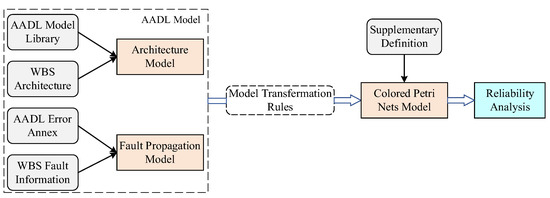
Figure 1.
An overview of this work.
The key contribution of this paper is the translation of the AADL design model into the Colored Petri Net model which supports reliability analysis. The new definitions added to CPN enable it to describe hierarchical systems, and the transformation rules from the AADL model to the hierarchical CPN model are proposed. This translation facilitates the use of AADL models in the quantitative reliability analysis domain.
The rest of this paper is structured as follows: Section 2 introduces the basic elements of AADL for airborne system modeling and shows the modeling process from component to system based on the WBS architecture. Section 3 shows the characteristics declared by the AADL error annex and the modeling approach of the error model, defines the error states and error events of the WBS, and builds the WBS fault propagation model on this basis. Section 4 provides the definition of the hierarchical CPN, the mapping relations between AADL and hierarchical CPN are proposed, and the CPN model of the WBS is presented. In Section 5, the quantitative reliability analysis of the WBS is implemented by Monte Carlo simulation of the CPN model, and the accuracy of the results is demonstrated using system components as examples. In Section 6, we conclude the paper.
2. The Wheel Brake System Model Based on AADL
2.1. The AADL Model of Airborne System Components
Airborne systems usually have a large number of subsystems and components. In order to model airborne systems, it is first necessary to determine the type of components and create different packages to contain the components. In AADL, execution platform components can be used for modeling airborne structural components and software components can be applied for modeling airborne software.
Execution platform components include processor, bus, device, etc. The processor can represent components with information processing functions such as airborne computers. The bus can represent the lines with flow properties in the airborne system, such as electrical lines and hydraulic lines. The device can represent components such as sensors and control units, which are the most widely distributed types of components in airborne equipment. The power supply device and electrical equipment in the electrical system can be modeled by the device, while the device can also model the hydraulic pumps and hydraulic valves in the hydraulic system.
Software components include data, process, etc. The data are used to represent the information transferred during the operation of the airborne system. The process denotes the software on which the airborne system operates. The software implements its functions by processing data input from outside the system. System components are utilized to model systems and subsystems with internal structures. The different components interact with each other through interfaces, which are mainly divided into power access, hydraulic access, and data port, and all of them can be represented using AADL elements. The correspondence between airborne system components and AADL types is listed in Table 1.

Table 1.
The correspondence between airborne system components and AADL types.
2.2. The Wheel Brake System Architecture
The high-level architecture of the system consists of a brake system control unit (BSCU), shutoff valves, metering valves, an accumulator, antiskid valves, a wheel brake, and a parking brake. Two independent hydraulic pumps (called Green Pump and Blue Pump) provide hydraulic supply to the wheels as a redundant configuration. The green pump is used for normal braking mode, and the blue pump is used as a backup pump when the normal hydraulic system fails. The conversion under various failure states is automatic or manual selection. The BSCU sends instructions to the hydraulic system after calculation, and the hydraulic values of the green pump, blue pump, and accumulator, as well as the hydraulic values output by the normal and standby systems, will also be fed back to the BSCU. The combination of software and hardware completes the realization of the function of the wheel brake system. The working principle of WBS is shown in Figure 2.
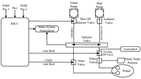
Figure 2.
Architecture of WBS.
2.3. The AADL Model of the Wheel Brake System
The wheel brake system is modeled in OSATE according to Figure 2. The model library is shown in Table 2. Figure 3 shows the AADL model of BSCU, which consists of subsystem 1, subsystem 2, select alternate, and other ports. BSCU is replicated with a redundant system (sub1 and sub2), and sub2 is the backup unit of sub1. When sub1 fails, the select component will select sub2 to work.

Table 2.
WBS model library.
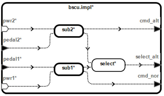
Figure 3.
AADL model of BSCU.
The BSCU subsystem is composed of a command unit, a monitor unit, and several ports. The command unit receives the data signal transmitted by the pedal, then transmits the skidding or braking instruction to the monitor unit through data ports. After receiving the signal from the command unit, the monitor unit will output the judgment signal to the select alternate unit. The BSCU subsystem model is shown in Figure 4.
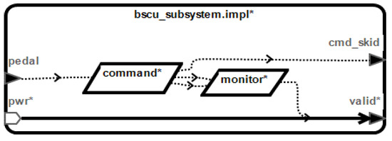
Figure 4.
AADL model of BSCU subsystem.
We establish a complete WBS model as shown in Figure 5 through the example provided by SAE ARP 4761 and the AADL model library as shown in Table 2.
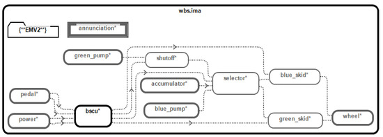
Figure 5.
AADL model of the WBS.
3. The Fault Propagation Model of the Wheel Brake System
Errors in the WBS components, as well as how these errors are generated and propagated, can be described in the AADL error model annex. This section presents the process of establishing the WBS fault propagation model.
3.1. AADL Error Model Annex
The AADL Error Annex defines the declaration rules and specific semantics for building error models. By describing the errors which may be generated by the component, as well as the error states resulting from error events within the components, the AADL Error Annex provides a detailed description of the fault propagation mechanism of the system.
For each AADL component, the error annex has two levels of description [27]: error model type and error model implementation. The error type defines the characteristics of the error state, error event, and error propagation; the error implementation defines the transition of the error state during the occurrence of the error event and the error propagation process. The specific characteristics declared in the error annex are as follows:
- Error propagation: indicating that the associated component port receives an output error, divided into In propagation and Out propagation;
- Error source: indicating that an error originates from within a component and propagates out of that component.
- Error sink: an error enters a component and is handled inside the component.
- Error path: describing how errors that originate outside of a component pass through the component.
- Error event: representing events that occur inside the component.
- Error state: defining the specific error states of state-machine error-behavior models.
- Error transition: defining the way the system transitions from one state to another, including the initial state, transition conditions, and termination state.
The AADL error library is the basis of the system error model, which consists of the error types and error behaviors of the components. The failure effects of all components in the system are declared in the error type library. The error behavior defines a model of system state changes due to internal faults or external errors. By referring to the error library and declaring the error propagation properties of the components, a failure propagation model of the system can be built.
An example of a single-component fault propagation model is shown in Figure 6. NoService error propagates into the component through green_input and blue_input ports, and no error propagates out, which means the component is an error sink. Operational and Failed are component states. Transition defines that component state changes from Operational to Failed after receiving a NoService error.
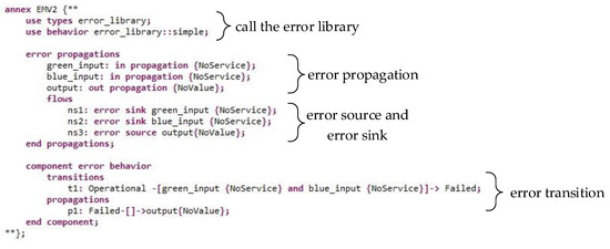
Figure 6.
Single component fault propagation model.
3.2. The Wheel Brake System Fault Propagation Model
We obtain the WBS fault propagation model by injecting the error annex into the built AADL model of WBS. The information acquisition of the error model can come from the content specified in the current reliability analysis manual. Part of the information from the traditional security evaluation model in ARP4761 can provide input for constructing the AADL error model. We first determine the error type and error state of the system components to build the error library. There are seven types of errors that occur in WBS, and each component has both operational and failed states. In addition, the BSCU component also has an alternate state (Alternate). When the sub1 fails, the sub2 is running, or the sub1 and sub2 are running, but the selected alternate unit fails, the BSCU is in this state. For WBS, there are also states such as annunciated braking loss and unannunciated braking loss. The error library of the WBS is shown in Figure 7.
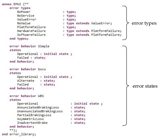
Figure 7.
Error library.
In addition to errors propagated through the component ports, error events occurring inside the component can also cause errors, causing the component state to change. The error events in the WBS and the components containing the error events are shown in Table 3.

Table 3.
Error events.
According to the established AADL model, add the error source, error sink, error path, error transition, and other information to the error annex of each component to build a complete error model. Figure 8 shows the fault propagation model of the BSCU subsystem in Figure 4. NoPower error is passed in from the pwr port, and NoValue error is passed in from the valid port. The state changes from Operational to Failed after NoPower error propagates into the component and the NoValue error is transmitted. The model also declares composite error behavior. When the command unit or the monitor unit fails, the subsystem component fails (Failed state), and when neither fails, the subsystem component is normal (Operational state).
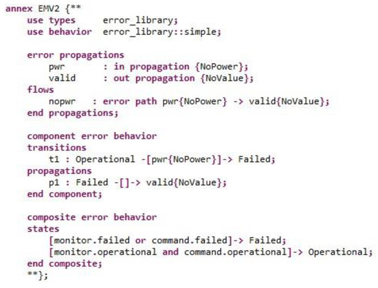
Figure 8.
Fault propagation model of BSCU subsystem.
4. The Wheel Brake System Colored Petri Nets Transformed from the AADL Model
4.1. The Definition of Colored Petri Net
The Petri net is a directed bipartite graph that includes two types of elements, places and transitions, represented by circles and rectangles. Places can contain any number of tokens [28]. After the appearance of Petri nets, many extensions to Petri nets were derived, such as Stochastic Petri nets [29], CPN, and GSPN [30].
A directed net is a triple :
Where P is a set of places, T is a set of transitions, F is flow relation, is the domain of F, , is the range of F, .
CPN adds the concept of color to the Petri nets. Different individuals can be distinguished by different colors, which can effectively reduce the complexity of the model. CPN can be defined as , where is a directed net and is the set of colors.
Because the AADL model has a hierarchical structure, this paper develops a hierarchical CPN model, which can accurately describe the relationship of components in different levels of the system, so as to realize the corresponding relationship between the AADL model and the CPN model. The supplementary definition is as follows:
Definition 1.
Timestamp: the timestamp is used to indicate the time of system simulation when the token arrives at the place, which is defined as .
Definition 2.
Guard: guard is a constraint of triggering the transition. EXPR is a set of constraints, , if , , and evaluates to true, the transition can be triggered; that is, the condition of guard is satisfied.
Definition 3.
Module: hierarchical CPN can be defined as a basic CPN with the module. , where . An interface is a port place through which the module connects with its environment. Port places have three types: input, output, and input/output which can be recognized by port tags (In, Out, and I/O). Due to the interface, the module exchanges tokens with the external net through a transition connected with the port, so the module is represented by a transition in the superior-level CPN model.
4.2. Rules of Transforming AADL-Based Models to Colored Petri Nets
Table 4 shows the basic AADL error model to CPN transformation rules.

Table 4.
AADL error model to CPN transformation rules.
Figure 9 shows an example of the CPN model transformed from the AADL error model shown in Figure 6. Green_input and blue_input receive errors as port “In”, and pass the token to the place “Operational”. Token transfers to the place “Falied” from the place “Operational” by triggering transition “t1” or “t2”, where [error = “greeninputnoservice”] and [error = “blueinputnoservice”] are the constraint of transition. Finally, the token is transmitted from the place “Failed” through the output port.
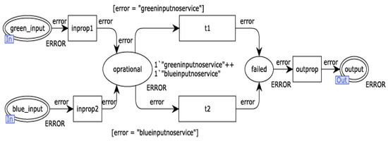
Figure 9.
CPN model of the component in Figure 5.
4.3. The Colored Petri Net Model of the Wheel Brake System
Figure 10 shows the CPN model of WBS obtained according to the transformation rules in Table 4. This model is the highest-level CPN model. Errors generated by pedal components and power components are transmitted to the BSCU through the port. Errors in BSCU, pumps, and accumulator propagate to the selector and shutoff valve, and finally to the wheel. All components in WBS are encapsulated in modules.
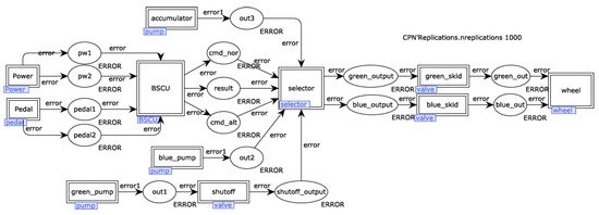
Figure 10.
CPN model of WBS.
Taking the BSCU module as an example, the expanded CPN model is shown in Figure 11. The pedal1 port and pedal2 port receive errors from the pedal component, and the pwr1 port and pwr2 port receive errors from the power component. Errors that propagate to the subsystem1 and subsystem2 module will then be passed to the select alternate module. Finally, the select alternate module will pass the error signal outward.
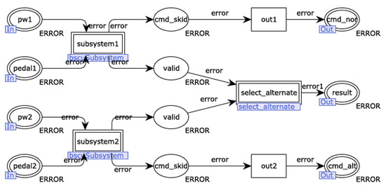
Figure 11.
CPN model of BSCU.
The expended CPN model of the command component in the BSCU subsystem module is shown in Figure 12, which is located at the bottom level of the WBS model. The command component inputs tokens via the pedalvalue port and processor port. No service, softwarefailure, and hardwarefailure error can, respectively, trigger the transition so that the command component changes from the operational state to the failed state. At last, errors propagate out through the brake port or skid port. There is a capacity place in the CPN model of the command component, which is connected to the failed place via transition. The capacity place is not an element in the transformation rules but is an additional modification of the model. When the command component fails and the error is propagated, the token in the failed place will be propagated from the port, causing the failed place to lose the token. However, in actual situations, the failed state will not change after the component propagates the error. Therefore, the capacity place is added to the model, and the token is injected so that the token will be passed to the failed place. The failed place always contains the token, which means that the component is in the failed state and has not changed.
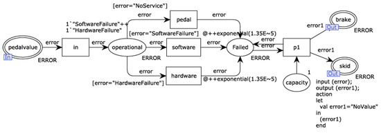
Figure 12.
CPN model of the command unit.
5. Reliability Analysis of the Colored Petri Net Model
5.1. The Result of the Analysis
In this paper, system reliability metrics are obtained by performing Monte Carlo simulations in CPN Tools. The CPN Tools is a tool that supports the modeling and simulation of Colored Petri Nets. In CPN Tools, it is possible to specify the random distribution function of transitions, and when the simulation is running, random numbers that follow this distribution will be automatically generated. Replication instructions can be used to achieve simulations for a given number of times, and the results of each simulation will be outputted to a replication report. The simulation process is as follows: after triggering each transition which represents an error event, a random number following an exponential distribution is generated and attached to the token, indicating the time when the error event occurs; the token is passed between ports in a chronological order, i.e., the earlier the error occurs, the more priority is propagated; the simulation ends when the system fails, at which point the simulation time is the system lifetime; a set of system lifetime samples can be obtained through multiple simulations.
The system reliability metrics are calculated from the system life samples. Taking the exponential distribution as an example, the reliability function of the exponential distribution is
Equation (1) can also be given as
By Equation (2), it can be seen that is directly proportional to t. Suppose N samples of system lifetime are obtained by simulation as t1 ≤ t2 ≤ ⋯ ≤ tN, and at that moment ti(i = 1, 2, ⋯ N), the corresponding approximate value of reliability is given as
According to Equations (2) and (3), we can obtain
If the fitted line of (xi, yi) on the coordinate axis is a straight line past the origin, then the lifetime sample follows an exponential distribution.
In reliability analysis, exponential distribution and Weibull distribution are the most widely used continuous distributions. The exponential distribution is commonly used to describe the lifespan of electronic components, and it can also be approximated as a failure distribution model for highly reliable complex systems. Weibull distribution has strong adaptability and can effectively describe the three stages of the bathtub curve. Therefore, we simulate 1000 times with exponential and Weibull distributions fitted to the lifetime samples of the WBS, respectively. The fitted lines are shown in Figure 13. The comparison of the fitted lines is given in Table 5.
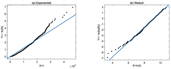
Figure 13.
Linear fitting of the WBS lifetime samples: (a) Exponential distribution; (b) Weibull distribution.

Table 5.
The goodness of fit of the fitted lines.
As we can see from Table 5, the Weibull distribution can be a better fit for the WBS lifetime, and the simulation yields the shape parameter β = 1.303 and the scale parameter α = 9.992 × 10³. The reliability function of the WBS can be approximated as:
The reliability of the system under a given operating time can be estimated according to Equation (5). For civil aircraft systems, we are usually concerned about reliability within the flight duration, which can vary from a few hours to over ten hours. Assuming a flight time of 10 h, Equation (5) yields reliability of the WBS greater than 99.98%.
5.2. Discussion
In order to verify the correctness of the simulation results, we simulate the pedal component and the battery component. According to Table 3, the pedal component lifetime follows an exponential distribution with a parameter of 3.4 × 10⁻⁵; the two error events of the battery component follow an exponential distribution with parameters of 1.35 × 10⁻⁵ and 6.75 × 10⁻⁵, respectively. The fitted lifetime parameters of the pedal component and the battery component are shown in Figure 14.
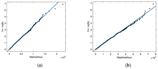
Figure 14.
Fitting of component lifetime parameters. (a) Pedal. (b) Battery.
The simulation results of the two components are shown in Table 6.

Table 6.
The simulation results of the two components.
By comparing the simulated and actual values of the distribution parameters, it can be seen that the simulation error does not exceed 3%, which is within the acceptable range. The R-square, also known as the coefficient of determination, is a measure of how well the linear regression model fits the data. R-square ranges from 0 to 1. In general, a higher R-square value indicates a better fit of the model to the data. As shown in Table 6, the R-squared values of the linear regression models for the pedal component and power component are both very close to 1, indicating that the simulated data can fit the lifetime distribution of the components well. Therefore, the correctness of the simulation results of WBS can be guaranteed.
To address the potential issue of overfitting, the fitting line can be validated by increasing the number of samples. Figure 15 shows the relationship between the additional 1000 simulated data and the fitting line obtained from Figure 13b. Meanwhile, we have calculated the R-square value of 0.9869 for the Weibull distribution fitting line on new samples, which indicates that the linear regression results have good generalization performance.
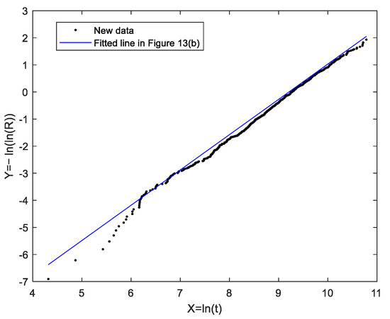
Figure 15.
The new sample data correspond to the fitted line in Figure 13b.
6. Conclusions
This paper uses AADL to model the wheel brake system in SAE ARP 4761 and builds the structural model and fault propagation model. At the same time, we propose the transformation rule from the AADL model to the CPN model. The CPN model of the WBS is established through the rules. By quantitatively analyzing the model via CPN Tools, we obtained the reliability analysis result of the WBS. The main contributions of this paper are as follows:
- The physical architecture and failure characteristics of the WBS are represented by AADL, and the fault propagation model is expressed by the error annex code with strictly defined semantics on the basis of the structural model. The consistency of the reliability analysis model and the design model avoids ambiguity in the comprehension of the system behavior and structure.
- Based on the additional definition of CPN, the transformation rules from the AADL model to the hierarchical CPN model are proposed. According to the transformation rules, the CPN model of WBS is established, which provides the foundation for reliability analysis. By converting to CPN, the deficiency of AADL in simulation analysis is made up.
- A Monte Carlo simulation is performed by CPN Tools to obtain samples of the system lifetime. The reliability metrics of the system are calculated based on a linear fit of the data samples. The analysis results can be automatically generated and modified as the model is modified, which reduces the workload of analysts.
However, this study has limitations. The reliability analysis of the WBS in this paper is based on the failure characteristics of components, without considering the influence of other factors on the system model. The model transformation rules proposed in this paper are specific to the reliability analysis process of this study and do not have universality for general AADL modeling. In future work, it is necessary to analyze systems in different flight phases and environments. Moreover, a general Petri net information extraction method will also be established based on AADL and error annex.
Author Contributions
Conceptualization, M.H. and D.C.; methodology, M.H.; software, D.C.; validation, M.H. and D.C.; formal analysis, D.C.; investigation, M.H.; resources, D.C.; data curation, D.C.; writing—original draft preparation, D.C.; writing—review and editing, M.H., D.C. and Z.L.; supervision, J.Z. and Z.L.; project administration, J.Z. and Z.L. All authors have read and agreed to the published version of the manuscript.
Funding
This research was funded by the National Natural Science Foundation of China (Grant No. U1733124), Aeronautical Science Foundation of China (Grant No. 20180252002), Funds for Civil Aviation Safety Capacity Building (Grant No. 2021-196).
Data Availability Statement
The data used to support the findings of this study are available from the corresponding author upon reasonable request.
Acknowledgments
This paper is developed from the conference abstracts named Reliability Analysis for Wheel Brake Systems Based on AADL. Based on earlier work, we improve the CPN model, refine the simulation procedure, and provide results for comparison and validation.
Conflicts of Interest
The authors declare no conflict of interest.
Abbreviations
| AADL | Architectural Analysis and Design Language |
| BSCU | Brake System Control Unit |
| CPN | Colored Petri Nets |
| FHA | Functional Hazard Assessment |
| FMEA | Failure Mode and Effect Analysis |
| FTA | Fault Tree Analysis |
| GSPN | Generalized Stochastic Petri Nets |
| IMA | Integrated Modular Avionics |
| MA | Markov Analysis |
| RBD | Reliability Block Diagram |
| SAE | Society of Automotive Engineers |
| SMGs | Stochastic Multiplayer Games |
| SOA | Service-oriented Architecture |
| WBS | Wheel Brake System |
| Nomenclature | |
| Σ | Set of colors |
| EXPR | Set of constraints |
| F | Flow relation |
| Module | CPN packaged in the transition |
| P | Set of places |
| R | Reliability |
| Reliability estimation value | |
| T | Set of transitions |
| token@time | Timestamp |
References
- SAE International. Guidelines and Methods for Conducting the Reliability Assessment Process on Civil Airborne Systems and Equipment; SAE International: Warrendale, PA, USA, 1996. [Google Scholar]
- Chen, L.; Jiao, J.; Zhao, T.D. Review for model-based reliability analysis of complex reliability-critical system. Syst. Eng. Electron. 2017, 39, 1287–1291. (In Chinese) [Google Scholar]
- Tech. Rep. AS5506; Architecture Analysis and Design Language (AADL). SAE International: Warrendale, PA, USA, 2004.
- Tech. Rep. AS5506/1; Architecture Analysis and Design Language (AADL) Annex Volume. SAE International: Warrendale, PA, USA, 2006.
- Cheng, D.W.; Lu, Z.; Yang, Y.P. Reliability Analysis for Wheel Brake Systems Based on AADL. In Proceedings of the 26th ISSAT International Conference on Reliability and Quality in Design, Miami, FL, USA, 5–7 August 2021. [Google Scholar]
- Yang, Z.-B.; Pi, L.; Hu, K.; Gu, Z.-H.; Ma, D.-F. AADL: An Architecture Design and Analysis Language for Complex Embedded Real-Time Systems. J. Softw. 2010, 21, 899–915. (In Chinese) [Google Scholar] [CrossRef]
- Liu, J.; Wu, X.G. Controller and architecture co-design of wireless cyber-physical systems. J. Syst. Archit. 2019, 94, 42–59. [Google Scholar] [CrossRef]
- Stewart, D.; Liu, J.; Cofer, D.; Heimdahl, M.; Michael, W.W.; Peterson, M. AADL-Based safety analysis using formal methods applied to aircraft digital systems. Reliab. Eng. Syst. Saf. 2021, 213, 107649. [Google Scholar] [CrossRef]
- Deng, P.Y.; Zhou, Q.; An, D.; Wang, S.H.; Li, K. A Modeling Method of Agents and SOA in Advanced Avionics System Based on AADL. Appl. Sci. 2022, 12, 8157. [Google Scholar] [CrossRef]
- Yang, Z.B.; Qiu, Z.K.; Zhou, Y.; Huang, Z.Q.; Bodeveix, J.P.; Filali, M. C2AADL_Reverse: A model-driven reverse engineering approach to development and verification of safety-critical software. J. Syst. Archit. 2021, 118, 102202. [Google Scholar] [CrossRef]
- Wang, P.; Zhao, C.; Yan, F. Research on the Reliability Analysis of the Integrated Modular Avionics System Based on the AADL Error Model. Int. J. Aerosp. Eng. 2018, 2017, 9358461. [Google Scholar] [CrossRef]
- Passarini, R.F.; Farines, J.M.; Fernandes, J.M.; Becker, L.B. Cyber-physical systems design: Transition from functional to architectural models. Des. Autom. Embed. Syst. 2015, 19, 345–366. [Google Scholar] [CrossRef]
- Chen, X.Y.; Zhu, Y.; Zhao, Y.; Wang, J.Y.; Altynbek, A. Hybrid Modeling and Model Transformation of AADL for Verifying the Properties of CPS Space-Time Compositions. IEEE Access 2021, 9, 99539–99551. [Google Scholar] [CrossRef]
- Wang, F.; Yang, Z.B.; Huang, Z.Q.; Liu, C.W.; Zhou, Y.; Bodeveix, J.P.; Filali, M. An Approach to Generate the Traceability Between Restricted Natural Language Requirements and AADL Models. IEEE Trans. Reliab. 2020, 69, 154–173. [Google Scholar] [CrossRef]
- Dong, Y.W.; Wang, G.R.; Zhang, F.; Gao, L. Reliability Analysis and Assessment Tool for AADL Model. J. Softw. 2011, 22, 1252–1266. (In Chinese) [Google Scholar] [CrossRef]
- Cheng, J.; Zhu, Y.A.; Qu, H.M. Analysis Software Reliability with AADL Error Model. J. Northwestern Polytech. Univ. 2014, 32, 1007–1010. (In Chinese) [Google Scholar]
- Hadad, A.S.A.; Ma, C.Y.; Ahmed, A.A.O. Formal Verification of AADL Models by Event-B. IEEE Access 2020, 8, 72814–72834. [Google Scholar] [CrossRef]
- Baouya, A.; Mohamed, O.A.; Bennouar, D.; Ouchani, S. Safety analysis of train control system based on model-driven design methodology. Comput. Ind. 2019, 105, 1–16. [Google Scholar] [CrossRef]
- Wei, X.M.; Dong, Y.W.; Sun, P.P.; Xiao, M.R. Safety Analysis of AADL Models for Grid Cyber-Physical Systems via Model Checking of Stochastic Games. Electronics 2019, 8, 212. [Google Scholar] [CrossRef]
- Hu, K.; Duan, Z.B.; Wang, J.Y.; Ga, L.C.; Shang, L.H. Template-based AADL automatic code generation. Front. Comput. Sci. 2019, 13, 698–714. [Google Scholar] [CrossRef]
- Jiang, Z.Y.; Zhao, T.D.; Wang, S.H.; Ju, H.Y. New Model-Based Analysis Method with Multiple Constraints for Integrated Modular Avionics Dynamic Reconfiguration Process. Processes 2020, 8, 574. [Google Scholar] [CrossRef]
- Yuan, C.; Wu, K.; Chen, G.; Mo, Y. An Automatic Transformation Method from AADL Reliability Model to CTMC. In Proceedings of the IEEE International Conference on Information Communication and Software Engineering (ICICSE), Chengdu, China, 19–21 March 2021. [Google Scholar] [CrossRef]
- Lu, Y.; Dong, Y.W.; Wei, X.M.; Xiao, M.R. A Hybrid Method of Redundancy System Reliability Analysis Based on AADL Models. In Proceedings of the IEEE International Conference on Software Quality, Reliability and Security Companion (QRS-C), Lisbon, Portugal, 16–20 July 2018. [Google Scholar] [CrossRef]
- Mian, Z.B.; Bottaci, L.; Papadopoulos, Y.; Mahmud, N. Model transformation for analyzing dependability of AADL model by using HiP-HOPS. J. Syst. Softw. 2019, 151, 258–282. [Google Scholar] [CrossRef]
- Zhang, Q.; Wang, S.; Liu, B. Approach for integrated modular avionics reconfiguration modelling and reliability analysis based on AADL. IET Softw. 2016, 10, 18–25. [Google Scholar] [CrossRef]
- Wu, D.H.; Wei, Z. Formal model-based quantitative reliability analysis using timed Coloured Petri Nets. Reliab. Eng. Syst. Reliab. 2018, 176, 62–79. [Google Scholar] [CrossRef]
- Rugina, A.E.; Kanoun, K.; Kaâniche, M. A System Dependability Modeling Framework Using AADL and GSPNs. Archit. Dependable Syst. IV 2007, 4615, 14–38. [Google Scholar] [CrossRef]
- Sun, Y.C.; Zhang, Y.J.; Li, L.B. Principles and Methods of Reliability; China Science Publishing: Beijing, China, 2016. [Google Scholar]
- Lu, Z.; Zhang, Z.W.; Zhuang, L.; Zhou, J. Reliability Model of the Fly-By-Wire System Based on Stochastic Petri Net. Int. J. Aerosp. Eng. 2019, 2019, 2124836. [Google Scholar] [CrossRef]
- Wang, J.B.; Dai, S.R.; Zhou, Y.; Gu, M.J. Research on GSPN-based Mission Reliability Modeling of Complexed Avionics System. Avion. Technol. 2020, 51, 1–5. (In Chinese) [Google Scholar]
Disclaimer/Publisher’s Note: The statements, opinions and data contained in all publications are solely those of the individual author(s) and contributor(s) and not of MDPI and/or the editor(s). MDPI and/or the editor(s) disclaim responsibility for any injury to people or property resulting from any ideas, methods, instructions or products referred to in the content. |
© 2023 by the authors. Licensee MDPI, Basel, Switzerland. This article is an open access article distributed under the terms and conditions of the Creative Commons Attribution (CC BY) license (https://creativecommons.org/licenses/by/4.0/).


