1. Introduction
Against the backdrop of continuous growth in traffic flow and increasing airspace density, flight conflict detection and resolution in air traffic management are particularly important in order to ensure airspace safety.
Flight conflict is defined as the overlapping of occupied space between aircraft during flight, the threat degree of which varies with the size of the occupied space and overlapping area [
1]. The commonly used conflict detection methods can be divided into probabilistic and deterministic methods [
2]. The deterministic method is the most widely used method in the engineering field, which solves the conflict problem by establishing a geometric model without considering the track error caused by the navigation accuracy. Flight conflict detection and resolution technology has received widespread attention, and multiple methods have been applied in practical research [
3,
4,
5]. The vertical obstacle (VO) method is a geometric method initially used to solve the path planning problem of robots [
6] and can meet the requirements of online obstacle avoidance [
7,
8,
9] due to its simplicity and good real-time performance. Many scholars have used the VO method to solve the flight conflict resolution problem [
10]. Luongo applied the collision cone to the three-dimensional collision avoidance of unmanned aerial vehicles [
11,
12] and verified the feasibility of the geometric algorithm through Monte Carlo random simulation [
13]. Wu proposed a flight conflict resolution algorithm combining the reciprocal speed obstacle method and the cubic B-spline in [
14], which can generate a smooth conflict resolution path for aircraft. In [
15], a 3D deterministic conflict detection algorithm based on the VO method was proposed to achieve the rapid judgment of flight conflicts with an ellipsoidal protection zone. Wang established a flight conflict resolution and track recovery model based on geometric optimization and minimum maneuvers in [
16], which successfully solved the conflict between cruise flights. Two main solutions have been extensively studied considering the huge computational cost in 3D collision avoidance problems: (i) solving 2D problems with a vertical adjustment strategy provided by classifying the conflict scene. However, this may lead to a single strategy without universality. (ii) The 3D collision avoidance model optimized by mathematical methods can be used for almost all scenes, while some complex equations need to be solved to obtain tangent planes.
This paper proposes a VO-based deterministic method that solves 3D flight conflict detecting and resolution problems, which can effectively overcome the shortcomings of existing research. A 3D flight conflict detection model is established considering the cylindrical protection zone, and PSO has been used for the optimal conflict resolution. An improved method with the search range optimized is proposed to simplify the relevant mathematical equations. The generality and flexibility of the method are effectively verified through simulation experiments in various scenarios. Compared to existing research, this paper innovatively addressed the following issues: (i) flight conflict problems in a 3D space considering the cylindrical flight protection zone; (ii) the huge computational burden of the 3D conflict resolution problem was reduced, making the method suitable for real-time solving; (iii) the flexible and general model can be widely used in more complex scenarios with variable requirements.
2. Flight Conflict Detection
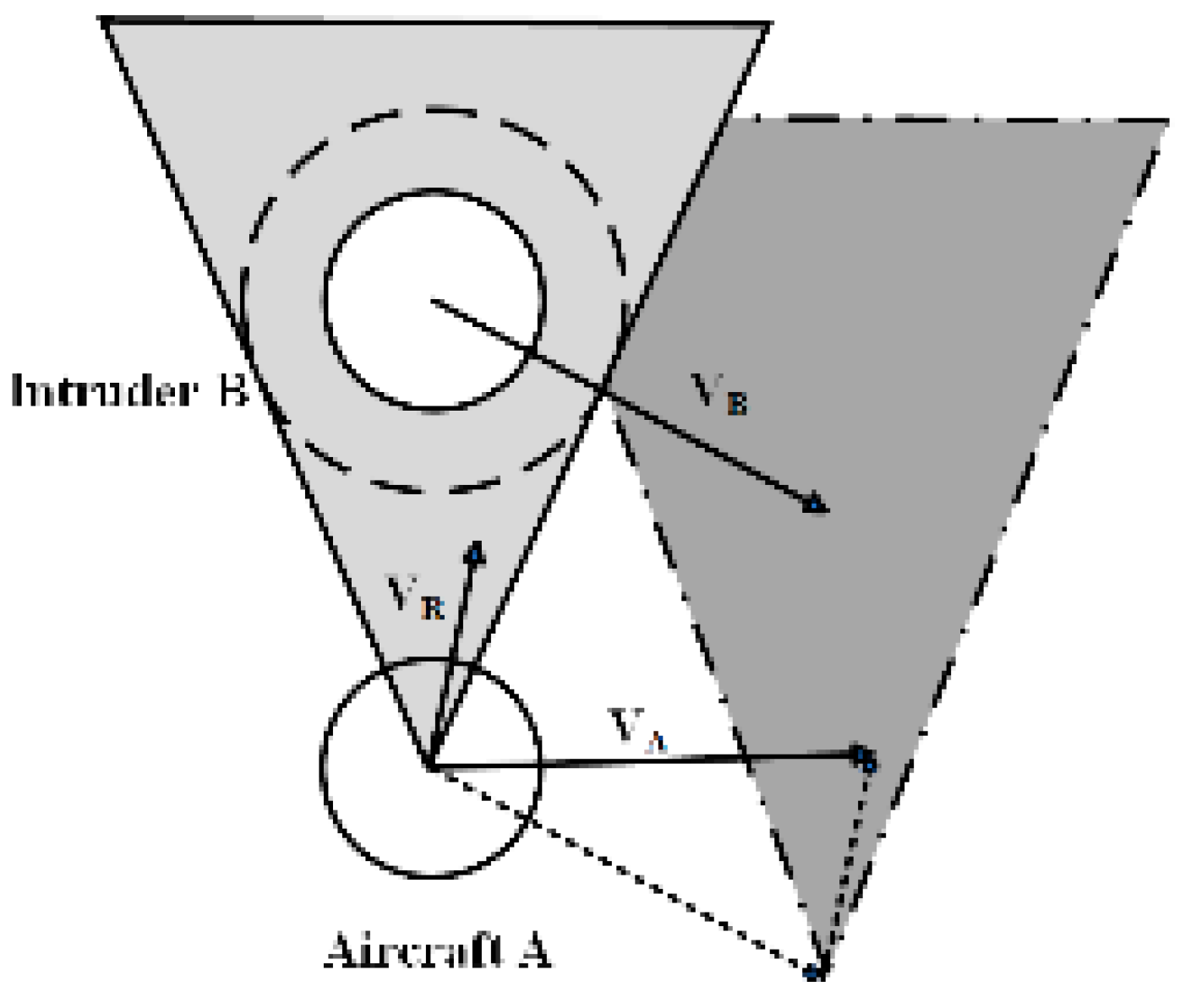
Flight conflict can be determined by the position relationship between the relative velocity and the relative collision cone (RCC) due to the principle of the VO method, as shown in
Figure 1. The velocity and flight attitude of aircraft A need to be adjusted to avoid collision with aircraft B when the relative velocity vector falls in RCC.
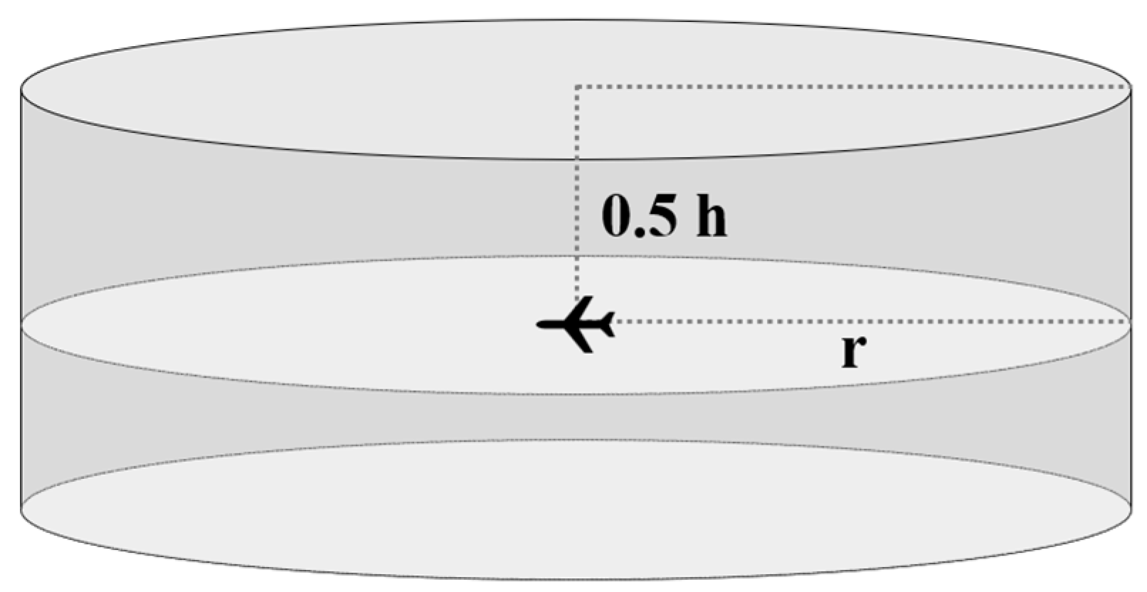
Taking the aircraft as the center, a cylindrical 3D region with an appropriate safety interval is selected as the flight protection zone, which is more approximate to the realistic situation (see
Figure 2). The cylindrical region can be defined as
where
and
are the radius and height of the protection zone, respectively. It is considered that a flight conflict occurs between two aircraft when their protection zones overlap.
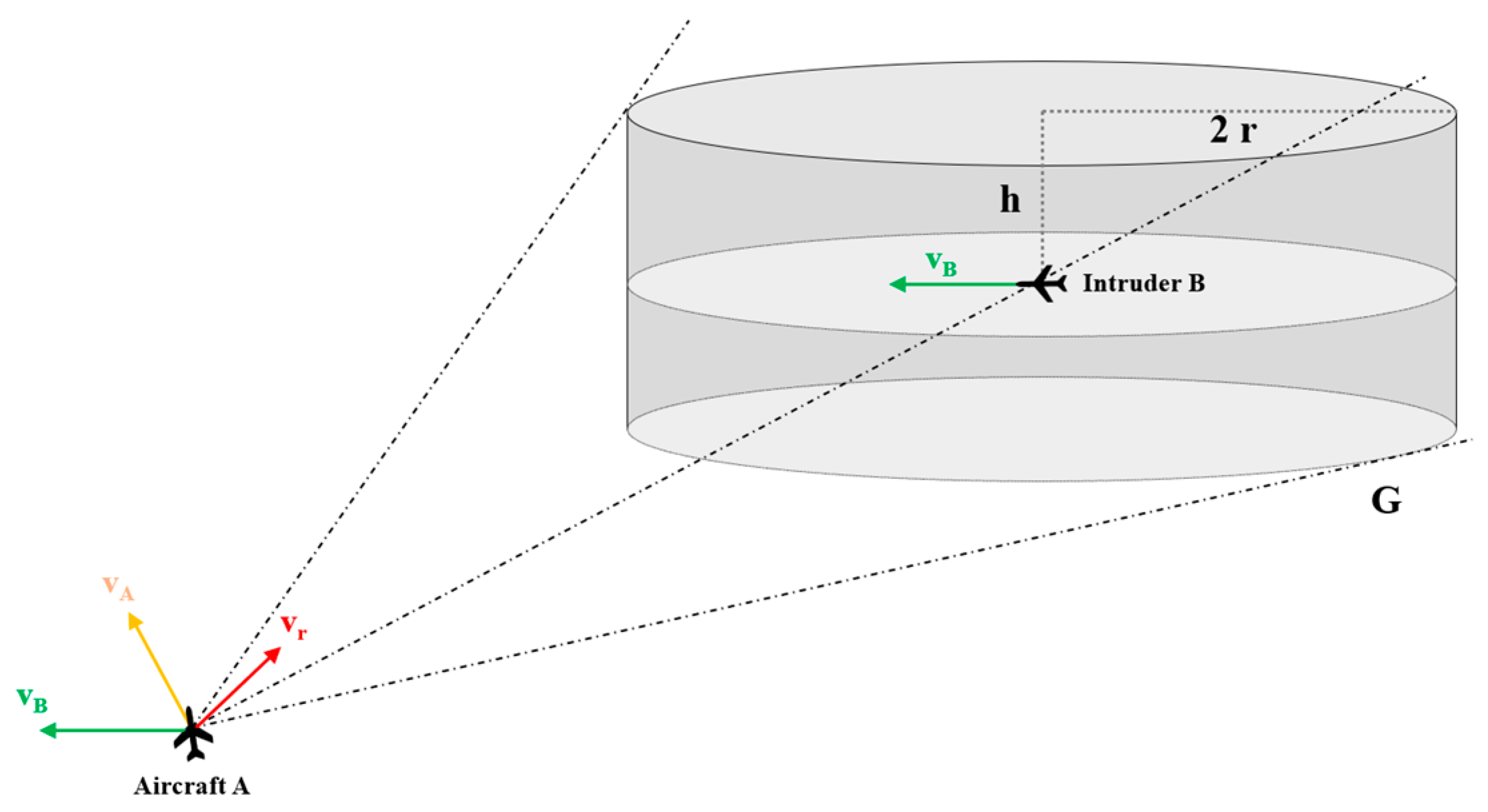
According to the principle of the VO method, aircraft A can be simplified as a particle, and the protection zone at the position of aircraft B expands into a cylinder
with a bottom radius
and height
, as shown in
Figure 3. The velocity vectors of the aircraft A and B are
and
, respectively.
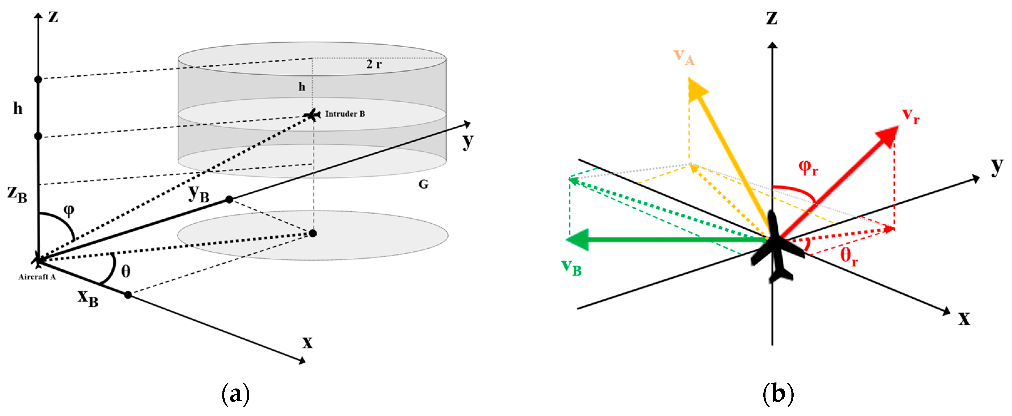
A 3D reference frame is established based on aircraft A and B, which are respectively located at origin O and a point whose coordinate is
, as shown in
Figure 4a. That means aircraft A flies from O in the direction of
, while aircraft B, which can be regarded as an intruder for aircraft A, flies from
in the direction of
. There may be a flight conflict between the two aircraft in a period of time, which is defined as an intersection of the protection zones of the two aircraft.
The position where the aircraft is located before and after a unit time step, whose coordination is expressed as
and
, can be used to determine the velocity. The horizontal deviation angle
and vertical deflection angle
of the aircraft are given by
The relative velocity vector is given by
, as shown in
Figure 4b. The magnitude
as well as angular variables
and
are given by the following expressions when the velocity vectors of the two aircraft are not parallel
where
, and
,
,
and
,
,
are the angular variables and velocity magnitude of aircraft
A and
B, respectively. Considering the properties of the tangent function, the sine and cosine function can be used to replace the tangent function through the Trigonometric functions transformation formula when there is no solution during the calculation.
Flight conflict is detected based on a 3D VO model. Consider that straight line
parallels to
and intersects with the surface of the
at point
, expressed as
where
,
and
, representing the coefficients of the linear equation in symmetric form; in other words, the vector
is parallel to the line. The scale parameter
can help to convert the symmetric form to parametric form. Conflict can be directly determined for situations with
parallel or perpendicular to the plane
.
The discriminant condition of the quadratic simultaneous equation obtained by combining Equations (7) and (8) is used to analyze the situation of the collision points. As shown in
Figure 5,
may intersect with
, making it necessary to further determine the position relationship between the
coordinate value of the intersection point and the cylindrical bottom surface based on the following condition:
The following three situations are given according to whether Equation (9) is met:
Only one intersection point meets the condition. This means that the flight conflict between two aircraft will occur in a period of time, and the collision point may be located on the flank or bottom surface of the cylinder;
Both of the two intersections meet the condition. A flight conflict will occur in a period of time, too, and the collision point will be closer to the origin;
None of the intersections meet the condition. In this case, whether the two intersections meet the following condition needs to be determined:
Aircraft A will collide with aircraft B only if Equation (10) is satisfied, and the collision point is located on one of the bottom surfaces of .
Based on the location of the collision point and
, the time when the flight conflict occurs
is given by
3. Conflict Resolution Based on PSO
We choose PSO to solve the flight conflict resolution problem and will introduce a general method with searching in solution space directly (SSSD) and an improved method with narrowing the search range (NSR) in this chapter.
PSO is a non-deterministic algorithm with the characteristics of self-organization, evolution and memory function. The process of searching and updating can be seen as following the current optimal point through which the particles in swarm can share information with others. Compared with the genetic algorithm, simulated annealing algorithm and ant colony optimization algorithm, PSO has simpler parameters and a faster convergence rate when dealing with complex problems [
17]. The inertia weight and learning factor are important parameters in PSO, which can affect the search range and convergence speed of the algorithm. PSO has been widely used in many fields, and related research has been conducted on improvement methods for algorithm performance improvement [
18,
19]. For example, dynamic inertia weight has been introduced in [
20] to achieve the rapid calculation of the 3D path planning of unmanned aerial vehicles. Parameters with linear and nonlinear variations may have different effects on the computational efficiency of the algorithm [
21].
We will discuss these two situations in subsequent chapters.
3.1. Obtain Flight Conflict Resolution Strategies
A better conflict resolution strategy should have smaller deviations. Set the fitness function
to measure the effectiveness of a strategy:
where
,
and
are used to describe the increment of the release velocity of aircraft A, and the impact of negative values can be eliminated by the use of squares. Due to the inconsistency in the units of variables including the horizontal deviation angle, vertical deviation angle and speed, as well as the significant differences in value ranges, weight coefficients
,
,
are introduced to realize normalization. In addition, the resolution strategies generated by the algorithm can have different tendencies by adjusting the value of the weight coefficients.
The positions of individuals in the particle swarm are given by the point coordinates in the vector space. The current optimal position of the individual in the particle swarm is obtained by comparing the fitness function value of the particle at its current position with its historical optimal value. After updating the individual’s optimal position, the global optimal position can be calculated, and the optimal solution with the minimum fitness function value can be found by iterative searching.
Some strategies are not suitable for conflict resolution, such as strategies with a large deflection angle or rapid velocity change. These undesirable strategies are sometimes the local optimal solutions found by the algorithm. Therefore, by setting the fitness function values of the bad strategies to a large constant, individuals in the particle swarm can return to regions which meet the conditions. Similarly, when there is a requirement to limit the solution range in subsequent chapters, a large fitness function value can also be set to achieve constraints on the conditions.
3.2. Searching in the Solution Space Directly
A series of rays emitted from origin
are tangential to G, forming the relative collision cone (RCC) and the tangent points
. The surface normal vector at tangent points can be expressed as
where
. The position relationship between the boundary of RCC and
needs to satisfy the following condition:
where
can be considered as the set of critical relative velocity vectors in collision scenarios, passing through both the origin
and a certain point
in set
.
The velocity vector of aircraft A is adjusted to
to avoid conflict, and the relative velocity vector becomes
. The critical condition for avoiding conflict between the two aircraft is that
is parallel to
, which can be expressed as:
Due to the non-differentiability of the connection at the bottom of the cylinder, the direct calculation of the set can be computationally complex. Therefore, we use the PSO algorithm search and approximate the optimal solution in a 3D space, which is presented in the form of a point denoted by . The optimal solution is considered to be obtained when the following conditions are satisfied:
N is in the set , which means that no conflict occurs with this velocity vector;
The optimal solution has a minimum value of .
The first condition needs to be determined for each particle based on the presented conflict detection model before calculating the fitness function value.
3.3. Narrowing the Search Range
The SSSD method can be used to stably obtain the optimal solution, while significant computational complexity and time consumption may be brought at the same time. Therefore, an improved method with narrowing the search range (NSR) is proposed to reduce the calculation cost based on the idea of the SSSD method.
The simplified expression of the set
can be obtained by narrowing the search range. As shown in
Figure 6, the tangent points are located on four segments which can be derived by solid geometry. The problem can be simplified to the search of the optimal solution on plane segments.
Compared to the SSSD method, the improved NSR method has the following two advantages:
Only whether the coordinate of the particle meets the value range needs to be determined, rather than whether the current velocity leads to flight conflict, and the former is simpler in calculations;
The value of a dimension is determined so that the 3D search space is reduced to 2D, resulting in a reduction in the computational cost.
Two issues need to be verified through experiments. The first is whether the improvement in the computational time can meet the requirements of real-time conflict resolution. Second, can we still find the optimal solution stably for all situations after narrowing the search range? Experimental verification will be provided in subsequent chapters.
4. Simulation and Experiment
4.1. Simulation Result of the SSSD Method
The radius of the flight protection zone is 10 km, and the altitude is 0.6 km.
As shown in
Figure 7a, the simulation setup refers to the banded shape simulation setup in [
22], two planes flying horizontally at a certain angle (vertical deviation angle
). In order to achieve a better verification effect, the traversal method with mesh division is used to replace the Monte Carlo method. The speed of aircraft A is 900 km/h, and the horizontal deviation angle
. Located at point
, aircraft B has a speed of 900 km/h and a horizontal deviation angle
. The linear distance between aircraft A and aircraft B is 72.77 km, and it is calculated that the two aircraft will collide with each other in 136.8 s.
In this section, we use the SSSD method based on PSO to obtain the optimal solution.
Figure 7b provides a schematic diagram of the 3D VO model, which corresponds to the simulation result in
Figure 7c. The blue cylinder represents the expanded protected zone in the 3D VO model, and the black line represents the relative velocity vector which intersects with the blue cylinder before or after executing the conflict resolution strategy and is tangential to the cylinder after completing the maneuver. Then, aircraft A will arrive at a new location at the original conflict moment, corresponding to the green cylinder (protected zone) in
Figure 7b,c.
It can be seen from
Figure 7 that the SSSD method suggests changing the horizontal deviation angle of aircraft A to
and descending by 300 m at a degree of 0.5. After implementing the strategy, aircraft A avoids aircraft B from the bottom left, and there is no conflict between the two aircraft.
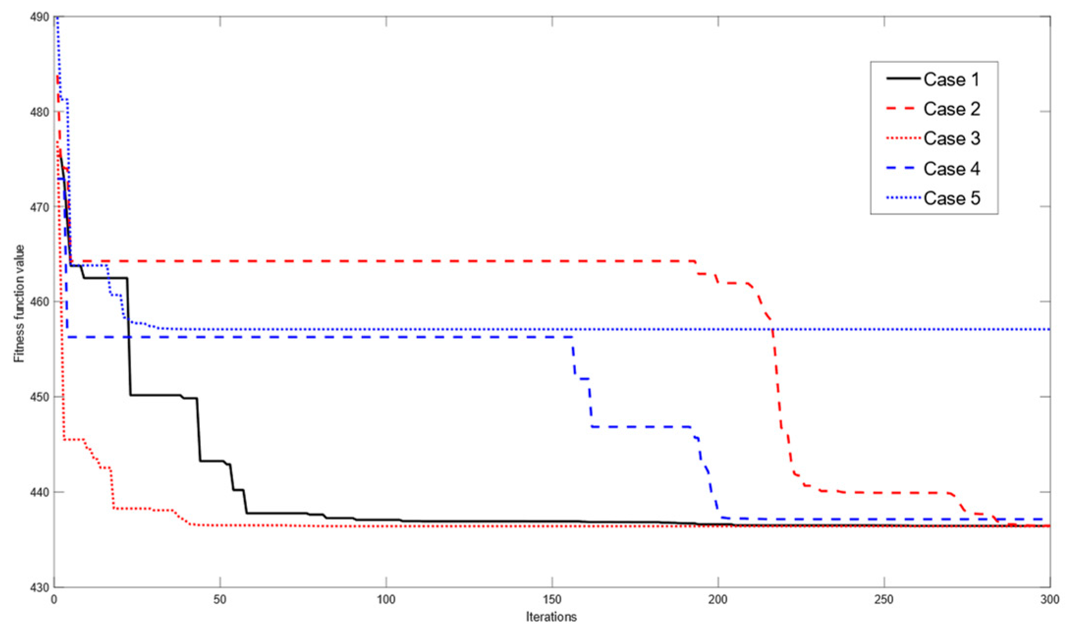
Next, we will explore the impact of the inertia weight and learning factor in PSO on the computational efficiency of the method. The learning factor and inertia weight can be set in forms of linear and nonlinear forms, expressed as
where
is the maximum number of iterations with a value of 300 and
is the iterative generation. The value of the inertia weight and learning factors will vary from the minimum (0.3) to the maximum (initial value).
,
and
are linearly decreasing, while
,
and
are non-linear decreasing by introducing an exponential term, and the parameter values of the latter have different change rates for different iterations. Based on the above expressions, five parameter combinations are set, as shown in
Table 1.
The iterative process of solving the optimal solution with different parameter combinations is shown in
Figure 8.
It can be seen in
Figure 8 that the inertia weight of nonlinear change can accelerate convergence. The changing learning factors can accelerate the solution to some extent. While they do not guarantee global optimality, they may lead to more iterations for finding the global optimum. Considering computational efficiency and accuracy, the subsequent experiments will use the nonlinear inertia weight and constant learning factor uniformly.
4.2. Simulation Result of the NSR Method
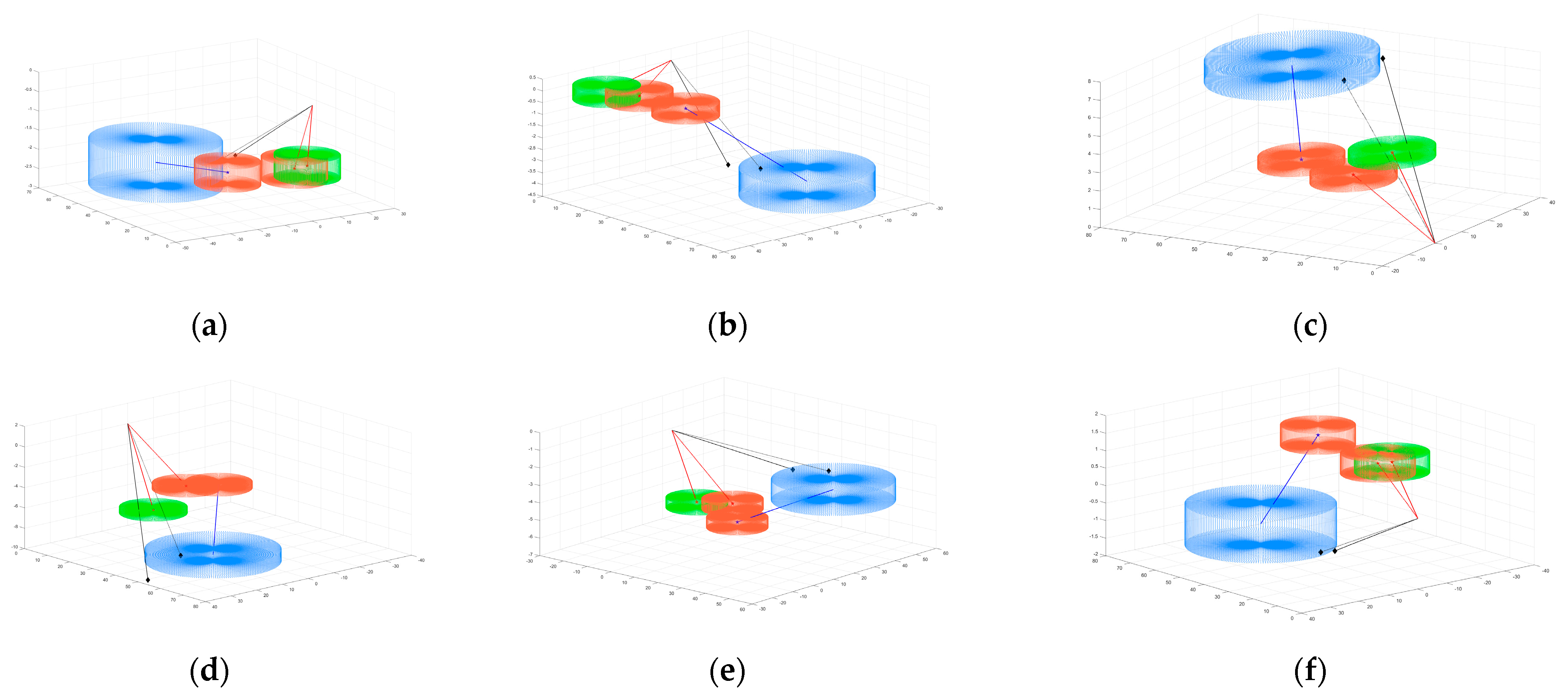
Considering (i) the deflection angle relationship and (ii) the flight state of the aircraft executing the resolution strategy, we adjust the scene parameters to set up six simulation scenarios.
Figure 9 shows the simulation results obtained by the NSR method.
Table 2 provides specific parameters and resolution strategies for each scenario, and a quantitative comparison of the solutions solved by the two methods is also given in
Table 2. The results indicate that the NSR method has a stable ability to search for the optimal solution, similar to the SSSD method. In addition, the calculation efficiency is represented by the calculation time, which is also shown in
Table 2. It can be seen that the narrowing of the search range significantly improves the calculation efficiency.
4.3. Generality of the NSR Method
According to the previous conclusion, the NSR method has the ability to solve flight conflicts in real time. In this section, we will utilize the advantage of a fast computational speed to detect multiple conflict scenarios and generate resolution strategies to verify the generality of the method. It is worth noting that the simulation scenarios set up in this section can substantially include all possible conflict situations between two aircraft. This persuasive method for simulation scenario designing was first used in [
22] and effectively validated their model. In this section, we will perform conflict detection on approximately 400,000 flight combinations and provide conflict resolution strategies for the combination which has flight conflict between the two aircraft, verifying whether the proposed method can be used properly in these different scenarios. A statistical analysis of various conflict situations and resolution strategy tendencies will be achieved in the meantime.
The moment when the two aircraft are 60 km apart is selected as the node for detecting conflicts and executing resolution strategies to simulate more of an emergency scenario. Aircraft A is on level flight, and aircraft B is located on the curved surface which is part of a sphere with a radius of 60 km, taking every in the horizontal direction as an angle and taking every in the vertical direction as an angle to obtain the initial position coordinates of aircraft B. The velocity vector of aircraft B is given in a similar way, taking every in the horizontal direction as an angle and taking every in the vertical direction as an angle . A total of 410,347 scenarios can be obtained through the above process. In addition, three different relationships of speed will be explored: (i) (A: 800, B: 900) km/h; (ii) (A: 850, B: 850) km/h; (iii) (A: 900, B: 800) km/h.
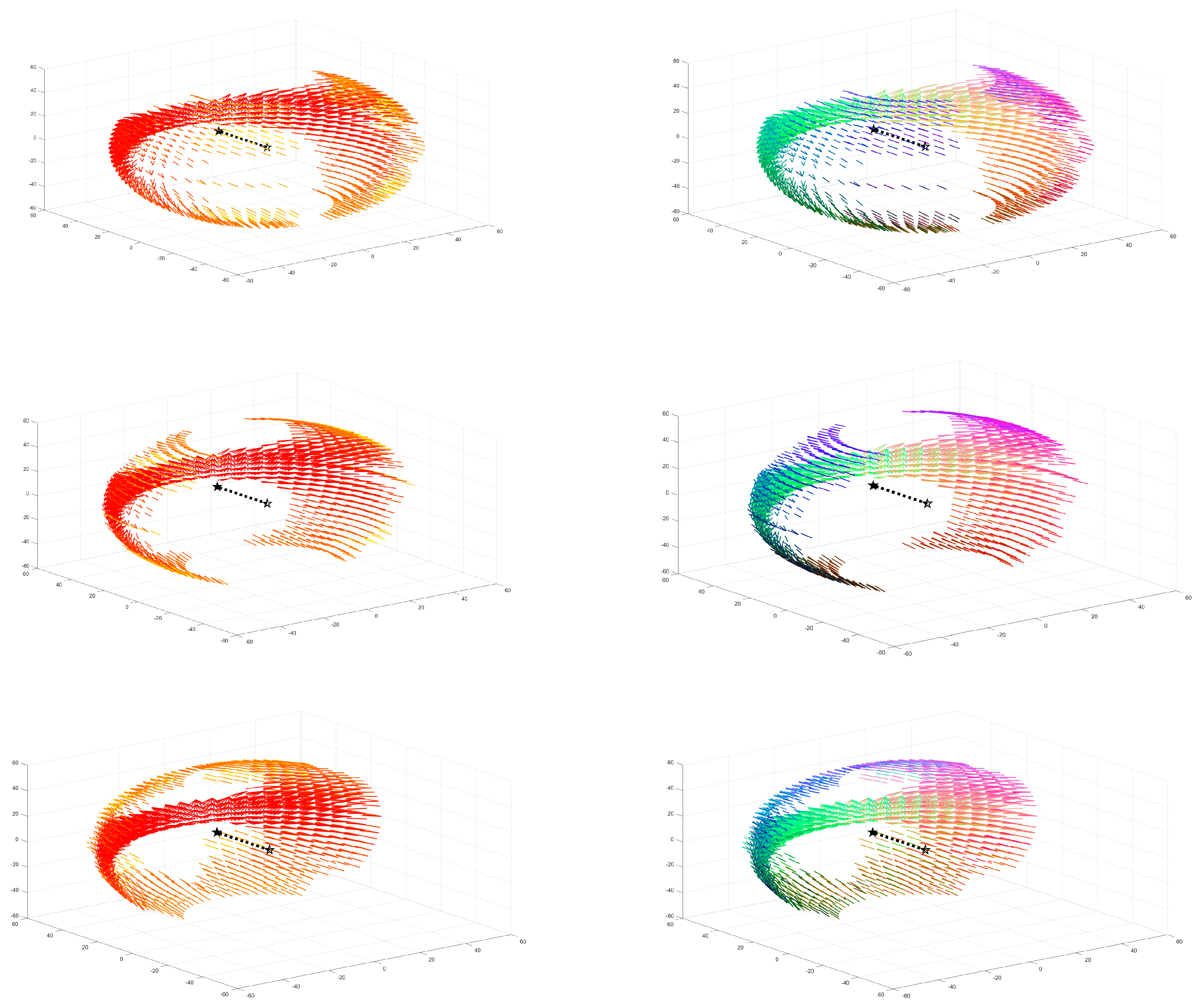
The situation of conflict scenarios is recorded in
Figure 10.
The initial position of aircraft A, namely, the origin, is marked with a hollow pentagram, and the velocity vector points to the solid pentagram along the dotted line. Record the conflict moment using colors in the form of . The closer the color is to red, the smaller the conflict time, which means the more urgent the conflict. There are a total of 2650 conflict scenarios in the speed combination (i), 2477 in (ii) and 2297 in (iii).
The resolution strategies are recorded by RGB color. The specific implementation process is to convert the resolution strategies provided by the NSR method into the form of , which are compared with the original velocity vectors to obtain the speed increment Normalizing according to , can be converted to the (0,1) interval, which can be used as the three elements of the RGB color matrix to obtain the corresponding color for the resolution strategies. According to the principle of RGB color matrix composition, the color blue represents the resolution strategies with vertical velocity changes, the color green represents horizontal y-axis velocity changes and purple (or red) represents horizontal x-axis velocity changes.
4.4. Flexibility of the NSR Method
The above results are the optimal solution based on the fitness function of the increment in speed of aircraft A. Different settings of the fitness function may lead to different tendencies of the resolution strategies. Filtering the optimal solution through the fitness function has an important advantage: the method is allowed to be easily modified to satisfy different conditions. The different performance of aircraft makes different strategic requirements. For example, some aircraft cannot use strategies with instantaneous lateral acceleration [
22], while others prefer to accept greater changes in the heading angle rather than speed [
16]. These requirements, as well as the introduction of aircraft priority that may need to be considered in the future, can be directly achieved through changes to the fitness function.
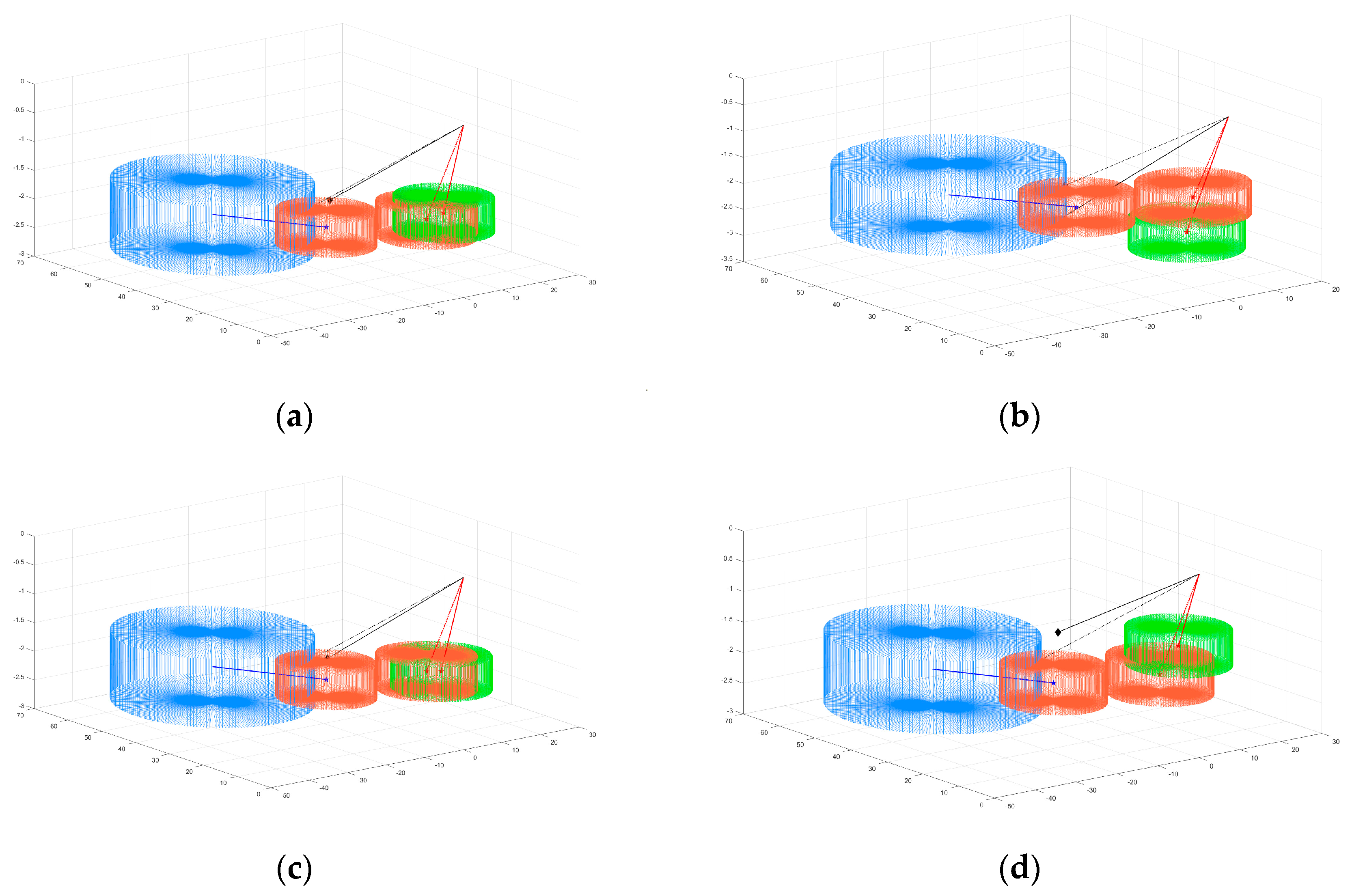
In this section, we will explore the effect of the weight coefficient of the fitness function
. Due to the small variable range of the vertical deflection angle, during the entire process of our research, the value of the vertical deflection angle has been expanded by about four times when calculating the fitness function value. On this basis, taking Scene 1 as an example, four weight coefficient combinations are discussed, and the parameter settings are shown in
Table 3. The solutions suggested by the NSR method are shown in
Figure 11.
It can be seen in
Table 3 that the extrication strategy of Scene 1 requires changes in the horizontal direction and speed, while the angle change in the vertical direction is relatively small without considering the weight coefficient. Combination II sets a large weight coefficient
, leading to an angle change in the horizontal direction of only
, which can be ignored. As a cost, the speed needs to be adjusted by 136.24 km/h. Combination III sets a large weight coefficient
, leading to the smallest vertical angle change. Combination IV sets a large weight coefficient
, leading to a constant speed resolution strategy, which is the most ideal scenario among the four combinations. The results indicate that the proposed method has strong flexibility, and by adjusting the value of the weight coefficient, different resolution strategies with different tendencies can be obtained. This feature enables the proposed method to be used in complex scenarios considering priority.
In addition, although the fitness function presented in this paper is composed of the increment of the velocity vector of aircraft A, according to the calculation principle of relative velocity, it is essentially the increment of the relative vector. The smallest fitness function is the smallest change in relative velocity. It is important that the change in relative velocity is the change in the velocity of aircraft A as well as the change in the velocity of aircraft B, so the aircraft executing the conflict resolution strategy is no longer limited to the own aircraft. Furthermore, it is possible to research a collaborative resolution strategy where both aircraft perform partial collision avoidance actions, and the implementation of this complex problem only requires modifications to the fitness function as well.
5. Conclusions
This paper proposes an optimization method based on PSO for flight conflict detection and resolution in a 3D space based on the VO method and achieves a rapid solution through the improved NSR method. The simulation results in various simulation scenarios show that the proposed method can quickly identify conflicts and provide the optimal resolution strategy, and the model is suitable for various scenarios. The NSR method can significantly shorten the calculation time without affecting the accuracy of the solution. The proposed method has great potential in applications. Reference strategies for air traffic controllers can be provided by the method due to the advantages of generality and great efficiency. In addition, the flexibility of the method will also enable it to respond well to the challenges posed by more complex airspace situations with different flight performances, mission natures and priorities.
Based on the research, the reciprocal VO method can be introduced in the next work to explore the conflict resolution problem of situations with multiple aircraft. Moreover, with the emergency of the fusion airspace, different flight characteristics need to be considered, and future research can consider the characteristics of aircraft based on the work of this paper, focusing on the safety guarantee issues of collaborative operation.
