Review

An Analytical Study of the Elements of Airworthiness Certification Technology Based on the Development of the Conversion of Diesel Engines for Vehicles to Aviation

1
Graduate School of Automotive Engineering, Kookmin University, Seoul 02707, Republic of Korea
2
Department of Automotive Engineering, Kookmin University, Seoul 02707, Republic of Korea
3
Aero System R&D Center, Aero System Business Group, Hanwha Aerospace, Asan 31409, Republic of Korea
*
Authors to whom correspondence should be addressed.
Aerospace 2023, 10(9), 738; https://doi.org/10.3390/aerospace10090738
Submission received: 13 June 2023 / Revised: 10 August 2023 / Accepted: 16 August 2023 / Published: 22 August 2023

Abstract

:
Aircraft reciprocating engines have been in operation over the past 100 years, which is a testament to their high levels of reliability and stability. Compared to turbine engines, reciprocating engines are at a disadvantage when it comes to high-speed flight. Nevertheless, they are widely used mainly for small aircraft thanks to their high specific power or power-to-weight ratio. Considering that propulsion systems account for approximately 40% of the aircraft price, lightness and high performance are key attributes of aircraft to achieve longer endurance. With the advantages offered by diesel engines, such as fuel economy, less maintenance, and a long lifespan, many attempts have been made to mount automotive diesel engines on urban air mobility and light aircraft. Recognizing advanced automotive diesel technology, where the power-to-weight ratio of the diesel engine is approximately 1 PS/kg, we analyzed a case where an automobile engine was converted for use in an aircraft. We focused on the Mercedes-Benz OM640 and the Austro AE300 and disassembled the two engines for comparative analysis. We then classified the engine components modified for aircraft use by (1) defining the major engine parts as fixed and alteration ones; (2) identifying the airworthiness-related alteration parts; and (3) categorizing the conversion purposes into classes A, B, and C. Components under class A were further categorized into subgroups in accordance with the airworthiness certification specifications outlined by the European Union Aviation Safety Agency. This helped determine the corresponding airworthiness standards for each subgroup. An inspection of the oil supply system revealed the need to apply safety wiring for some components to prevent possible oil leakages, which can be caused by the pressure difference with increasing altitude. Moreover, given that sensor manufacturers are required to present guidelines for sensor redundancy through numerous designs and tests and secure single-fault tolerance, we established criteria for selecting and applying sensors and separating sensors that must be made redundant from ones that are not subject to sensor redundancy.

1. Introduction

The rapid growth of the urban air mobility (UAM) industry has allowed the concept to evolve into an intelligent system, a new version of the mobility industry, through industry convergence involving big data, satellite services, cutting-edge sensor applications, and geographic information systems. In this fast-changing industrial landscape, the demand for light aircraft in the fields of forestry, agriculture, meteorological observations, and coast guards has skyrocketed. This, in turn, has led to the steady growth in demand for UAM to effectively navigate prolonged surveillance, communications, and a range of interactions [1,2,3,4]. However, global supply chains cannot keep up with the rising demand due to technological limitations [5]. Although electrification warrants special attention in the UAM sector, internal combustion engines can outperform electric motors through longer endurance [6,7,8]. With their excellent durability and mileage, diesel engines are also being leveraged in various fields [9,10]. Moreover, diesel engines are considered suitable for long flights. However, it is difficult to enter the aviation industry where diesel engines are applied due to the difficulty of implementation technology, except for in a few countries. In other words, there is difficulty in acquiring the technology due to the absence of the internalization of core technology. Accordingly, it is dependent on imports from a small number of companies that develop and manufacture aviation diesel engines worldwide. Therefore, the need to share aviation conversion development technology is constantly being raised.
The development of aircraft diesel engines entails the airworthiness certification process, which ensures that the aircraft meets its design, manufacturing, assembly, and equipment requirements and is in a condition for safe operations. International aviation organizations have outlined airworthiness certification criteria [11,12,13,14]. However, this rigorous certification process to comply with international aviation standards has seen some mechanical difficulties in developing aircraft diesel engines. By disassembling two engines (an automobile engine and an aircraft engine converted from an automobile engine) and analyzing them, this study aimed to lay the foundation upon which diesel engines satisfying airworthiness certification criteria can be developed. This engine conversion proves challenging, and a wide array of systems and components must be modified and upgraded, reinforcing the safety features of electronic control systems and increasing the thermal and heat resistance of the fuel supply and cooling lines to meet the airworthiness certification specifications. Considering the Mercedes-Benz OM640 and Austro AE300 as engine conversion cases, we disassembled the two engines for comparative analysis to assess the possibility of modifying automotive engines for aircraft use and creating development blueprints. The fuel efficiency of the AE300 engine was improved by applying common rail direct fuel injection, and engine control was automated by applying the FADEC (Full Authority Digital Engine Control) system. Similarly, a high-efficiency turbocharger was applied to minimize performance degradation as the altitude increased. In addition, the AE300 engine was mass-produced after modification and development about 15 years ago, and problems were supplemented by continuously issuing ADs (Airworthiness Directives) and SBs (Service Bulletins) [15,16,17]. Therefore, it was judged that it is a state-of-the-art technology worth researching at the present time. As a result, as a benchmarking study through direct disassembly, it provides solutions for unopened aviation conversion factors and technologies and aims to reduce the research gap between countries and institutions through the analysis.

2. Experimental Devices and Methods

A benchmark study measures and compares usability metrics against a baseline study during new product or technology development [18,19,20]. Therefore, benchmarking can be used to compare two or more engines, derive areas for improvement, and develop better products [21,22]. Moreover, it can accelerate the process of developing aircraft diesel engines while reducing time and cost. This study employed the following equipment and methodology.

2.1. Experimental Devices

2.1.1. Engine Selection

To explore the case of modifying an automotive diesel engine for use in an aircraft, this study compared the Mercedes-Benz OM640 and the Austro AE300 engines in a comparative analysis [23,24,25]. Table 1 highlights the improved power performance (by 28 PS) when an automobile engine was converted into an aircraft one. This can be attributed to the turbocharger upgrade. With an increase in altitude, the air becomes thinner, thus reducing the engine power. When this happens, increasing the boost pressure can raise the effective compression ratio [26,27] and, ultimately, the engine torque and power. Meanwhile, the dry weight of the engine decreased by 5 kg, from 168 kg to 163 kg. In short, the power-to-weight ratio improved from 0.83 PS/kg to 1.03 PS/kg, with an increase in power and weight reduction.

2.1.2. EASA Airworthiness Certification Data

Airworthiness refers to criteria for minimizing safety risks that may arise from system failure. It aims to ensure an aircraft’s suitability for safe flight by mandating the application of safety-related technologies. The airworthiness certification process verifies the application of aviation safety technologies and assesses the capabilities of relevant aircraft systems to maintain the required safety levels. All systems and components are subject to country-specific airworthiness certification, and systems and components that have obtained an airworthiness certificate are installed only on the affected aircraft. An airworthiness certificate can be issued upon meeting the airworthiness-related criteria, which are determined based on the reliability, safety, and maintainability of aircraft and their systems [28,29,30,31].
The Certification Specifications and Acceptable Means of Compliance for Engines (CS-E) is one of the EASA airworthiness certification specifications. It governs the assessment and verification of aircraft system safety and prescribes the certification processes to determine whether an aircraft can be deemed airworthy [32]. All systems subject to an airworthiness certification go through a series of verification processes that encompass system requirement specifications, design verification, system integration and verification, and system certification. Additionally, the airworthiness certification process covers the risk assessment of systems, system implementation methods and requirements, and system maintenance methods. To evaluate the system performance, tests and verifications are conducted in real-world settings. Complying with all these specifications can translate into securing aircraft system safety, which leads to earning an airworthiness certificate. Table 2 summarizes the main CS-E items used in this study.

2.2. Research Method

The two selected engines were disassembled to conduct a comparative analysis in the following steps [33,34].
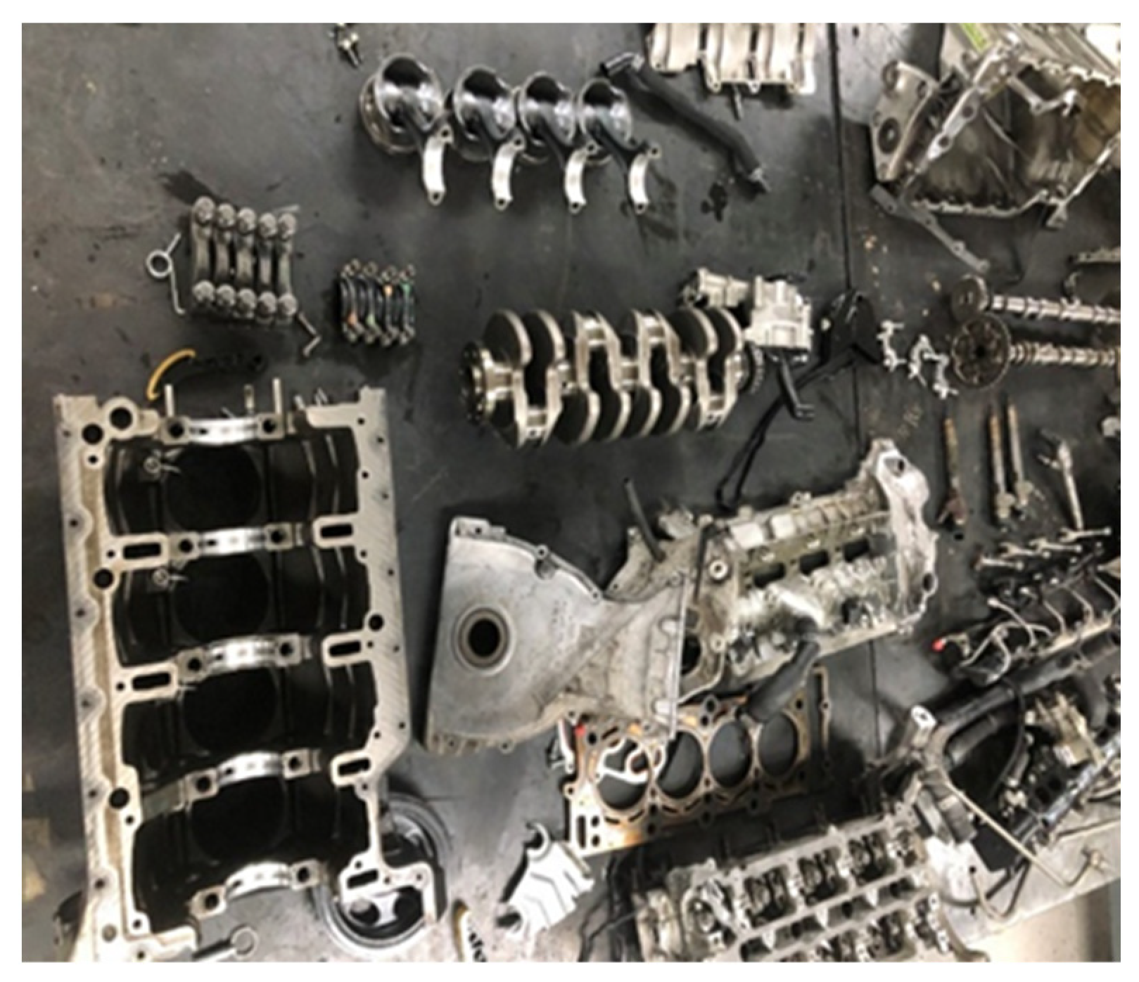
  • Detaching the engines’ external parts: Accessories and components attached to the outsides of the engines were removed. This preparatory work was performed before gaining access to the engines’ bodies.
  • Removing the engine block and head: The engine blocks and heads that protect the internal components were removed, allowing access to the insides of the engines.
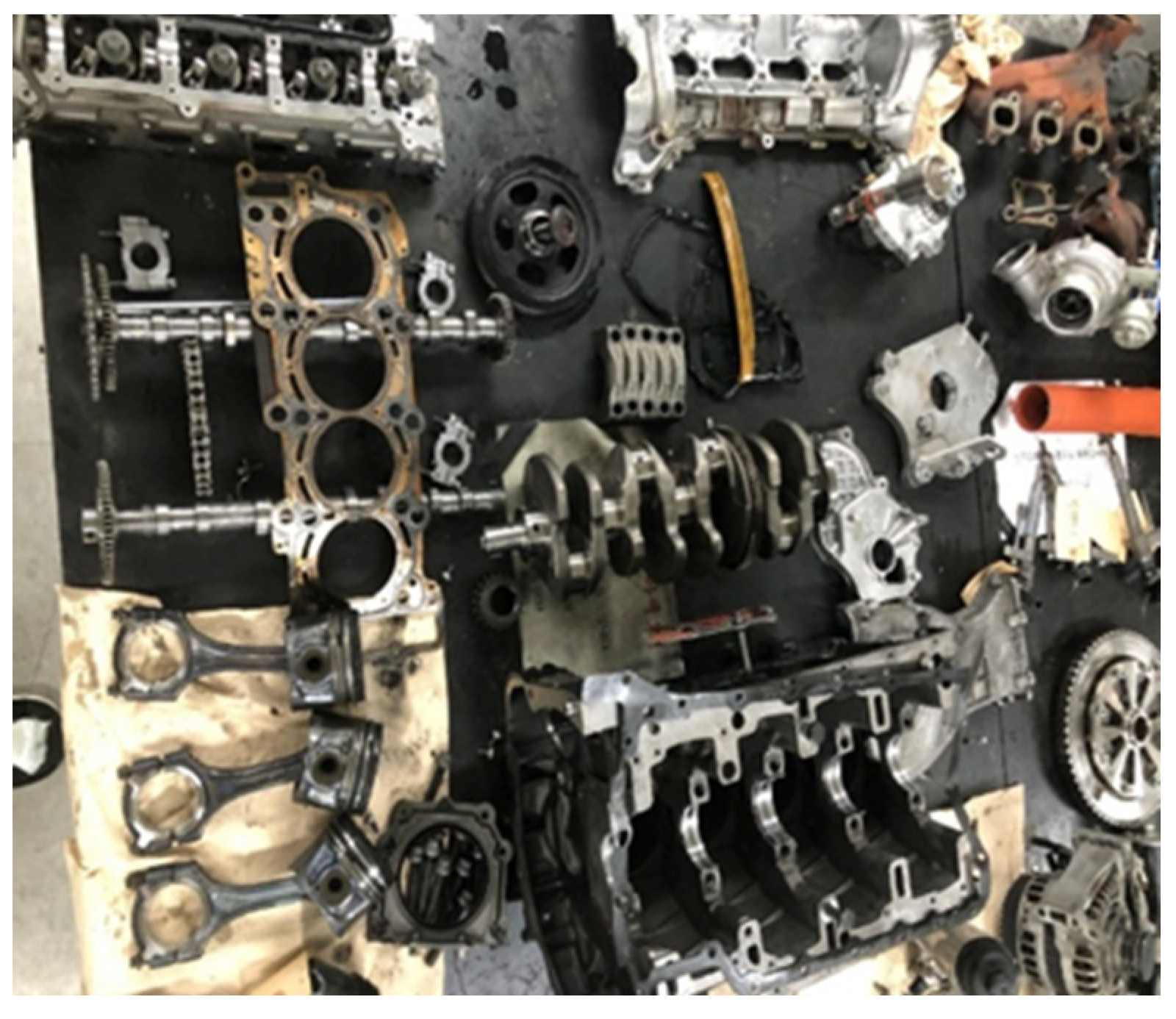
  • Disassembling the engines’ internal components: A wide range of components comprising the engines’ bodies were disassembled. In this stage, components such as the crankcase, cylinder head, piston, camshaft, and valve were disassembled, and their conditions and performance were examined.
  • Cleaning: After disassembling the engines, each separate component was cleaned. This task entailed removing dust, oil, and contaminants and inspecting their condition.
Figure 1 and Figure 2 show the disassembled OM640 and AE300 engines.

2.2.1. Classification of the Engine Components Modified for Aircraft Use

In this process, the components modified for aircraft use were classified depending on the safety and airworthiness requirements [35]. To this end, various engine parts were defined as either parts that remained unaltered (hereinafter denoted as the “fixed parts”) or parts that were modified for performance enhancement, airworthiness, and layout (hereinafter denoted as the “alteration parts”). Among the alteration parts, the components that were modified to meet the airworthiness requirements were categorized under class A. This classification process helped determine each component’s eligibility for certification based on the airworthiness certification specifications. Furthermore, additional safety devices and other certification-related requirements needed for each component can be ascertained.

2.2.2. Requirements for Material Selection and Anti-Loosening

Requirements for material selection refer to the conditions that must be considered when selecting materials for specific purposes. These conditions are determined by various factors depending on the environment where specific components or products are used, including their purposes and functions [36,37]. Typical requirements for material selection include durability, corrosion resistance, thermal resistance, fire resistance, tensile strength, impulse strength, and processability. For example, impact resistance is of utmost importance for aviation parts, given the numerous shocks and vibrations experienced during a flight [38]. Additionally, the importance of thermal and fire resistance cannot be overemphasized, considering that high temperature and pressure affect aircraft performance [39,40]. Therefore, in addition to physical characteristics, chemical and economic characteristics must be taken into account when determining the requirements for material selection.
Clamping force represents the ability to respond to friction generated in the joint parts and serves to ensure the stability and safety of an aircraft during a flight. In terms of safety-related components, anti-loosening devices, such as safety wire (locking wire), thread lockers, Nord-Lock washers, and locknuts, are essential [41,42,43,44]. First, bolts fastened to both the fixed and alteration parts were sorted, and the manual provided by Austro was consulted to compile the information on anti-loosening requirements, oil and water leaks, and tightening torque [45,46,47]. Through the Austro Engine Illustrated Part Catalogue, the names and locations of actual engine bolts were identified, and their size, length, pitch, and number were measured and compiled.

2.2.3. Sensors Subject to Redundancy

Aircraft sensor redundancy secures aircraft safety and stability and refers to a technology developed to prevent single faults that may arise in electronic equipment [48,49]. Redundant sensors significantly contribute to aircraft safety by addressing the single-fault condition in an effective manner. As such, sensor redundancy plays an integral role in boosting aircraft reliability [50,51]. Given the close relationship between aircraft sensors and aviation safety, it is imperative that the sensor redundancy system be introduced promptly. As a precondition, it is necessary to ascertain the sensor redundancy system’s scope of application while identifying sensors that need to be made redundant. Furthermore, attention should be paid to airworthiness certification specifications and detailed criteria for separating sensors that are subject to redundancy from those that are not. Airworthiness certification criteria do not specify designs and installation requirements for individual sensors but only require that the stability for each group of sensors be secured (e.g., single-fault tolerance). Therefore, introducing the sensor redundancy system calls for a thorough review of all aircraft sensors from a stability perspective. As for new additional sensors, developers may decide whether to carry over the existing sensor-related standards into the engine and sensors to be developed; however, it is essential that they make sensors that are critical for aircraft safety redundant (wherever needed). In summary, when selecting aircraft sensors, their suitability for air operations should be prioritized. Moreover, their roles in determining their eligibility for redundancy should also be taken into account.

3. Results

3.1. Classification of Components Modified for Aircraft Use

The engines were disassembled, and the fixed and alteration parts were identified for classification [52]. For key fixed parts, such as the cylinder block and head, only the shape of the joint parts was maintained for those components whose functions (e.g., exhaust gas recirculation) were not required in aviation. For components that were not subject to airworthiness requirements, their automotive materials remained unchanged. As illustrated in Table 3, this study categorized the modified automotive parts into three classes depending on the conversion purpose. Class A includes components subject to the requirements of sensor redundancy, the prevention of oil leakage through double locking, and heat or fire protection according to the CS-E classification. These are essential components needed to meet airworthiness certification requirements. The eligibility of these components for each of the major CS-E items (CS-E 50, CS-E 80, CS-E 90, CS-E 130, and CS-E 250) was analyzed. CS-E 50 is for single-fault tolerance or sensor redundancy, while CS-E 90 and CS-E 130 require flame resistance related to heat or fire protection and corrosion resistance, respectively. CS-E 80 and CS-E 250 are related to double locking and require the prevention or minimization of fuel and engine oil leaks.
Table 4 exhibits the components of the alteration parts that were classified into the performance enhancement, airworthiness, and layout categories. Out of 24 components, 11 were modified to meet airworthiness requirements. It was confirmed that modifying the design of the alteration parts entailed a thorough review of airworthiness specifications, such as sensor redundancy, material selection, and fastening conditions.
Table 5 summarizes the analysis results of engine conversion for class A. CAS, CPS, BPS, and IATS were made redundant, and material change and reinforcement were identified in the common-rail return line, water outlet, water inlet pipe, and GPC harness.

3.2. Requirements for Material Selection and Anti-Loosening

In the AE300 engine, various materials were added to secure flame resistance and degradation protection, required by airworthiness certification specifications (CS-E 90 and CS-E 130). Material change and reinforcement were identified in the existing common-rail return line, reflecting the fact that the components that deliver high-pressure fuel, a flammable fluid, must secure flame and corrosion resistance. The material of the water inlet pipe was changed from plastic to aluminum to secure corrosion resistance and durability against the load generated by engine operations. A double clamp was newly installed in the water outlet with the shape change in the hose part, except for the thermostat and the material change from plastic to silicon. Material change and reinforcement were carried out in the cable of the GPC harness to secure flame and corrosion resistance. Table 6 shows the list of the components with material changes, and Figure 3 illustrates a picture of such components.
Safety wire, one of the anti-loosening requirements, is used to fix bolts and nuts to a structure. When a bolt comes loose, using a safety wire can counteract this problem by tightening the wire. Safety wire can be used around the head of a bolt and nut and the vibrating parts. Owing to safety wiring, a properly fastened bolt can contribute to preventing loosening. CS-E 80 and CS-E 250 require the use of safety wire to reinforce the anti-loosening ability and, thus, prevent oil and water leakage from oil-supplying devices. Table 7 lists the areas subject to safety wiring.
Areas in which bolts and nuts are fastened may suffer from oil or water leaks due to internal pressure or external shocks [53]. To tackle this problem, sealing is performed using washers made of softer metal than the bolt and body. This can prevent the release of gas or liquid and secure airtightness [54]. Given the extremely harsh conditions that aircraft often encounter, potential oil and water leaks seriously compromise aircraft safety. In this respect, a high level of performance, stability, and maintainability is required for fastening components such as washers. Additionally, these components must have the attributes of being weatherproof and thermal- and moisture-resistant. As shown in Figure 4, airtightness was secured by sealing the gas and liquid present in the hydraulic systems or joint parts using a washer made of a softer metal (copper or aluminum) than the bolt and body.

3.3. Sensors Subject to Redundancy

Among the AE300 engine sensors, CAS, CPS, BPS, and IATS were classified as the ones that must be made redundant because these sensors are directly involved in sensing the power controls of the diesel engine, such as fuel injection and intake flow. While CAS recognizes the top dead center and detects piston positions from the crank angle, thus helping determine the exact fuel injection timing, CPS monitors the stroke of each cylinder by recognizing camshaft positions and helps control fuel injection sequentially. BPS optimizes the operation condition of a turbocharger by providing the boost pressure data, while IATS measures the intake air temperature and, thus, helps compensate for temperature-specific changes in density [55]. As the above demonstrates, sensor redundancy is of utmost importance in improving aircraft safety. Should one sensor malfunction or fail, the other sensor takes over and the system can continue to operate seamlessly. This can minimize potential risks and reduce the likelihood of an accident. According to the operation manual of the AE300 engine, these sensors are categorized as Electrical Engine Control Unit (EECU) A and B banks. When a disruption is detected in one of the banks, the internal voter switches to the other channel and secures single-fault tolerance (relevant airworthiness certification specification: CS-E 50). In other words, a single fault in the EECU of one of the banks instantly prompts the internal voter to switch to the other channel for seamless operations. Thus, redundant sensors enhance the overall reliability of a system. Manufacturers determine sensor redundancy after considering various factors, including safety issues (e.g., plane crashes) through numerous designs and tests. Table 8 summarizes the sensors that must be made redundant.
Sensors are not subject to redundancy when they have no direct effect on aircraft safety and a pilot’s workload. For the AE300 engine, these sensors were classified as shared sensors based on the schematic of the operation manual. Shared sensors have no primary effect on sensing for engine power control, which is attributable to the fact that redundant sensors are directly involved in the engine’s main operations to secure safety; instead, shared sensors engage in the engine’s internal management based on the values received from redundant sensors. Although shared sensors play a vital role in maintaining and optimizing an engine’s efficiency and stability, they are not subject to redundancy because they are not as important as sensors that must be made redundant. Therefore, shared sensors assume an auxiliary role in the engine system, and it is believed that any failure of one of these sensors does not significantly affect overall safety. However, given the fact that sensor failure can compromise aviation performance, regular inspections and the maintenance of shared sensors are strongly advised. Table 9 lists the sensors that are not subject to redundancy.
Based on the maintenance manual, the coolant temperature sensor (CTS) is divided into the CTS, which measures coolant temperature, and the CTS_GPC, which measures GPC coolant temperature. The CTS_GPC distinguishes itself from a typical CTS, as it directly communicates with the GPC and is not subject to redundancy like the CTS. A typical CTS detects the engine coolant temperature and provides the temperature data to the engine management system. For example, when faced with a high coolant temperature, the engine management system reduces the engine power or cools the engine to prevent the engine from being overheated. While directly communicating with the GPC, the CTS_GPC monitors the cooling of the engine’s glow plug. The CTS_GPC works independently of the typical CTS and regulates the temperature of the glow plug system to maintain the engine’s overall performance and stability. The above rationale exempted both the CTS and CTS_GPC from being made redundant. Figure 5 exhibits the schematic of the CTS.
In conclusion, when installing sensors in aircraft, attention should be paid to the airworthiness certification specifications and detailed criteria for separating sensors that are subject to the sensor redundancy system from those that are not. Among the AE300 engine sensors, CAS, CPS, BPS, and IATS were classified as sensors that must be made redundant, whereas the other sensors were classified as shared sensors that were not subject to the sensor redundancy system. Sensors subject to redundancy are directly involved in regulating the engine power based on the amount of fuel injected. In contrast, shared sensors do not have a primary effect on engine operations. This means that the successful implementation of the sensor redundancy system can enhance aircraft safety by forestalling operational disruptions. Table 10 illustrates the schematic of the two types of sensors.

4. Conclusions

This study delved into airworthiness certification technologies centered on engine conversion, involving an automotive diesel engine (OM640) and an aircraft engine (AE300), and subsequently analyzed the engine components affected by this conversion process. The analysis results of this study are as follows.
  • The components of the alteration parts were analyzed from three different perspectives: performance, airworthiness, and layout. Based on this analysis, the automotive engine components modified for aircraft use were classified under classes A, B, and C depending on such perspectives.
  • Based on the EASA airworthiness certification specifications, components under class A, which were subject to sensor redundancy, double locking, and heat or fire protection, were grouped according to the CS-E items. This grouping is expected to serve as a guideline for fabricating new components.
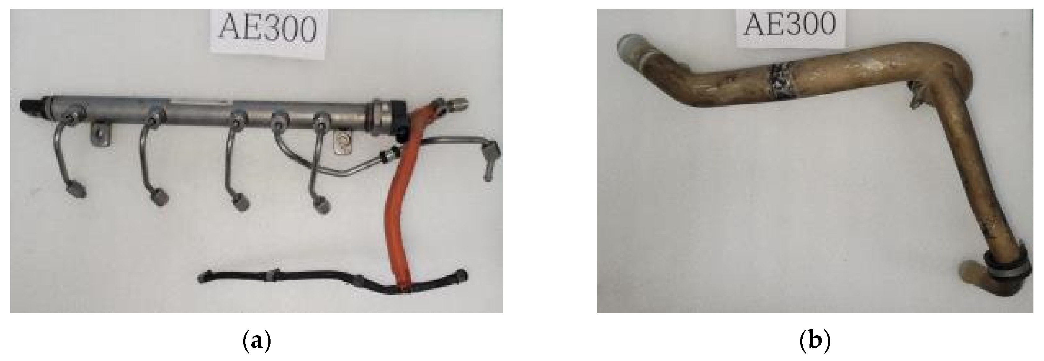
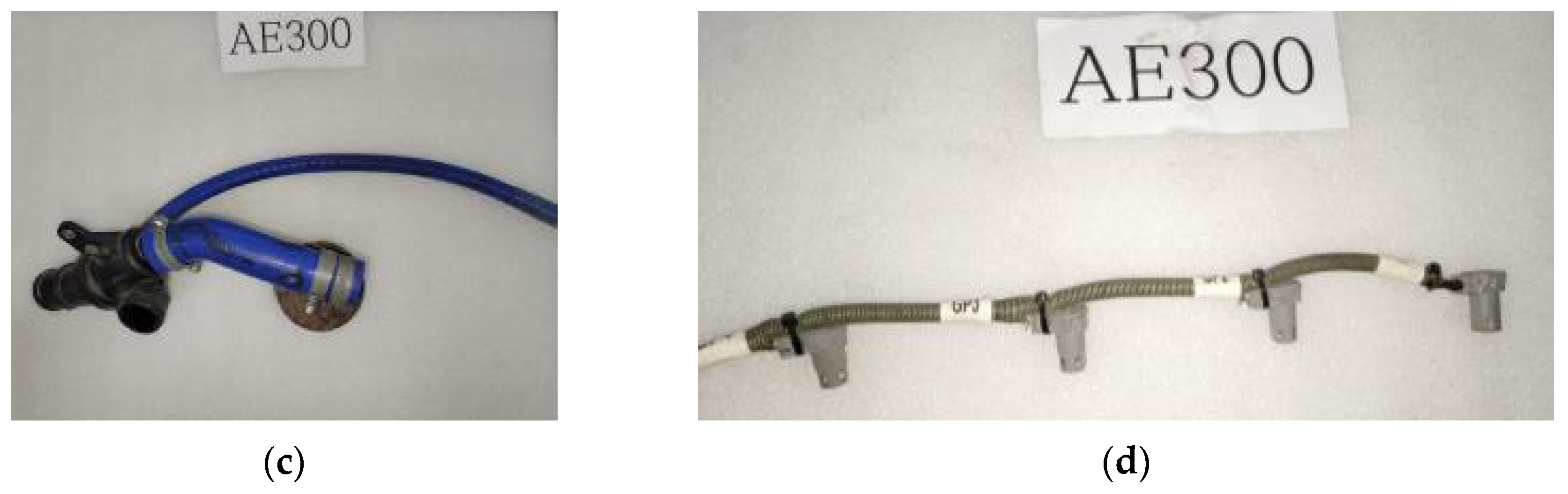
  • To secure the required flame resistance and degradation protection, material reinforcements were made in the fuel lines, cooling lines, and harness components.
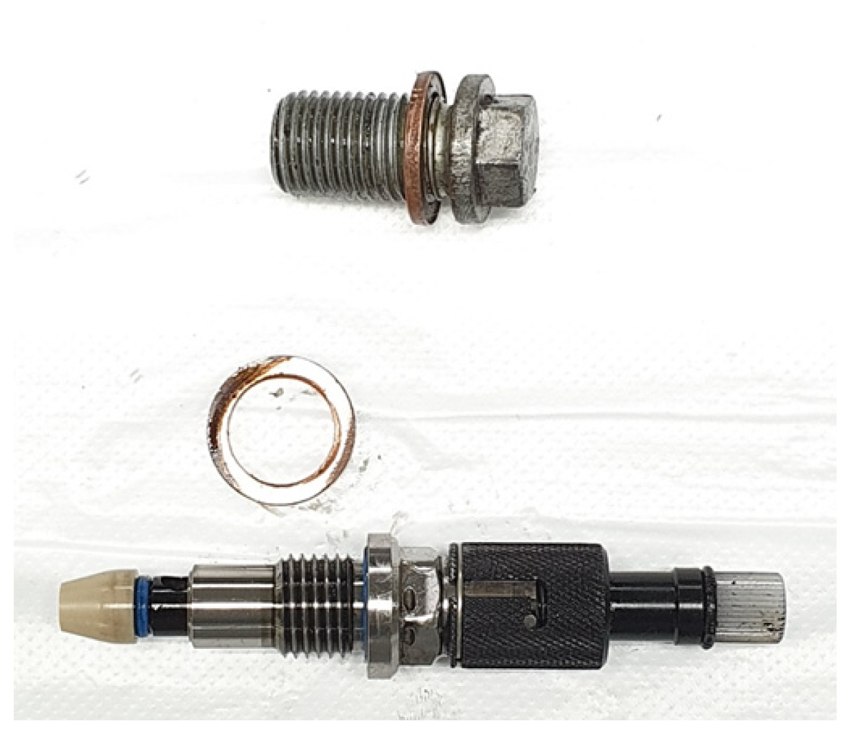
  • Moreover, the anti-loosening ability was reinforced through safety wiring to prevent potential oil leakages from the oil-supplying devices.
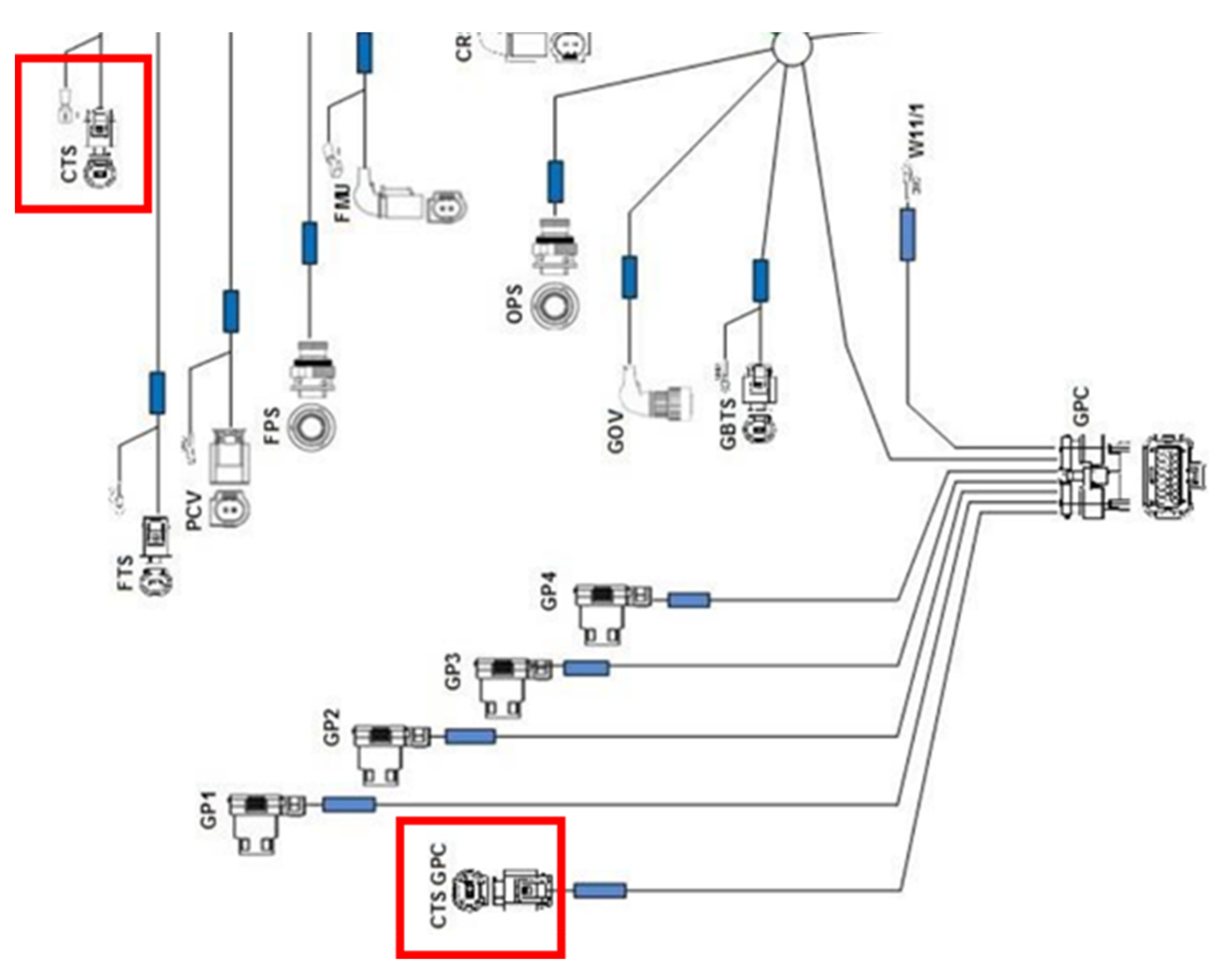
  • To secure single-fault tolerance, sensor redundancy was extensively explored, and detailed sensor-related criteria were presented, including the ones that distinguish sensors subject to redundancy from shared sensors.
The basic data derived from this study are expected to facilitate the integrated development encompassing the design, testing, and verification of aircraft reciprocating engines in many countries and drive the nation’s engine development capabilities to the next level.

Author Contributions

Conceptualization, S.L. and G.P.; methodology, J.L., S.L. and J.C.; investigation, J.L. and G.P.; supervision, Y.K. and G.P.; writing—original draft, J.L. and S.L.; writing—review and editing, J.L., S.L. and G.P. All authors have read and agreed to the published version of the manuscript.

Funding

This work was supported by a Korea Research Institute for Defense Technology Planning and Advancement (KRIT) grant funded by the Korean government (DAPA(Defense Acquisition Program Administration)) (KRIT-CT-21-028) through the BK21 Program grant funded by the Korean government (MOE; Ministry of Education) (No. 5199990814084).

Institutional Review Board Statement

Not applicable.

Informed Consent Statement

Not applicable.

Data Availability Statement

All necessary data have been reported in this article and there are no other data to share.

Conflicts of Interest

The authors declare no conflict of interest.

Abbreviations

The following abbreviations are used in this manuscript:
UAMUrban air mobility
EASAEuropean Union Aviation Safety Agency
CS-ECertification Specifications and Acceptable Means of Compliance for Engines
FADECFull Authority Digital Engine Control
ADAirworthiness Directive
SBService Bulletin
CRICommon Rail Injector
EDCElectronic Diesel Control
LOTCLoss of Thrust Control
LOPCLoss of Power Control
IPCIllustrated Part Catalogue
CASCrank angle sensor
CPSCam position sensor
HPPHigh-pressure pump
CTSCoolant temperature sensor
IATSIntake air temperature sensor
BPSBoost pressure sensor
GPCGlow plug control
EECUElectrical Engine Control Unit
APSAtmospheric pressure sensor
OLSOil level sensor
OTSOil temperature sensor
OPSOil pressure sensor
RPSRail pressure sensor
FPSFuel pressure sensor
FTSFuel temperature sensor
OTS_GGearbox oil temperature sensor

References

  1. Hasan, S. Urban Air Mobility (UAM) Market Study; Crown Consulting, Inc.: Washington, DC, USA, 2019; No. HQ-E-DAA-TN70296. [Google Scholar]
  2. Straubinger, A.; Rothfeld, R.; Shamiyeh, M.; Büchter, K.-D.; Kaiser, J.; Plötner, K.O. An overview of current research and developments in urban air mobility–Setting the scene for UAM introduction. J. Air Transp. Manag. 2020, 87, 101852. [Google Scholar] [CrossRef]
  3. Rothfeld, R.; Straubinger, A.; Fu, M.; Al Haddad, C.; Antoniou, C. Chapter 13—Urban air mobility. Demand Emerg. Transp. Syst. 2020, 267–284. [Google Scholar] [CrossRef]
  4. Bulusu, V.; Onat, E.B.; Sengupta, R.; Yedavalli, P.; Macfarlane, J. A traffic demand analysis method for urban air mobility. IEEE Trans. Intell. Transp. Syst. 2021, 22, 6039–6047. [Google Scholar] [CrossRef]
  5. Fedorov, E.; Mingazov, A.; Ferenets, A. Features and limitations in the design of a light aircraft generation system. In Proceedings of the 2021 International Conference on Electrotechnical Complexes and Systems (ICOECS), Ufa, Russian Federation, 16–18 November 2021; IEEE: Piscataway, NJ, USA, 2021. [Google Scholar]
  6. Rendón, M.A.; Sánchez R., C.D.; Gallo, M.J.; Anzai, A.H. Aircraft hybrid-electric propulsion: Development trends, challenges and opportunities. J. Control. Autom. Electr. Syst. 2021, 32, 1244–1268. [Google Scholar] [CrossRef]
  7. Tiimus, K.; Murumäe, M.; Väljaots, E.; Tamre, M. High-Efficiency Internal Combustion Engine Used in the Unmanned Aircraft. Solid State Phenom. 2015, 220–221, 928–933. [Google Scholar] [CrossRef]
  8. Serbezov, V.S.; Nikolova, M.I. Comparative study of the energy efficiency of diesel and hybrid powered light aircraft. IOP Conf. Ser. Mater. Sci. Eng. 2020, 1002. [Google Scholar] [CrossRef]
  9. Xin, Q. Diesel Engine System Design; Elsevier: Amsterdam, The Netherlands, 2011. [Google Scholar]
  10. Heywood, J.B. Internal Combustion Engine Fundamentals; McGraw Hill: New York, NY, USA, 1988. [Google Scholar]
  11. Clothier, R.A.; Palmer, J.L.; Walker, R.A.; Fulton, N.L. Definition of an airworthiness certification framework for civil unmanned aircraft systems. Saf. Sci. 2011, 49, 871–885. [Google Scholar] [CrossRef]
  12. Kritzinger, D. Aircraft System Safety: Assessments for Initial Airworthiness Certification; Woodhead Publishing: Soston, UK, 2016. [Google Scholar]
  13. Haddon, D.R.; Whittaker, C.J. Aircraft airworthiness certification standards for civil UAVs. Aeronaut. J. 2003, 107, 79–86. [Google Scholar] [CrossRef]
  14. Batuwangala, E.; Silva, J.; Wild, G. The regulatory framework for safety management systems in airworthiness organisations. Aerospace 2018, 5, 117. [Google Scholar] [CrossRef]
  15. EASA. “Type Certificate Data Sheets” TCDS No.: E. 200, Issue: 12, 30 June 2020, Austro E4 Series Engines, Austro Engine GmbH, Rudolf-Diesel-Straße 11 A-2700 Wiener Neustadt, Austria, Initial Issue, 28 January 2009. Available online: https://www.easa.europa.eu/en/document-library/type-certificates?search=E.+200&year=&year_to= (accessed on 12 June 2023).
  16. EASA. “Airworthiness Directive” EASA AD No.: 2021-0203R1, TCDS Number(s): EASA.E.200, Effective Date (Original Issue): 14 September 2021, Austro Engine GmbH, Austria, Issued: 24 September 2021. Available online: https://www.easa.europa.eu/en/document-library/type-certificates?search=E.+200&year=&year_to= (accessed on 12 June 2023).
  17. Rudolf-Diesel-Straße 11 A-2700 Wiener Neustadt, “Mandatory Service Bulletin” No. MSB-E4-035/2, Supersedes MSB-E4-035/1; Austro Engine GmbH: Wiener Neustadt, Austria, 2021.
  18. Dattakumar, R.; Jagadeesh, R. A review of literature on benchmarking. Benchmarking Int. J. 2003, 10, 176–209. [Google Scholar] [CrossRef]
  19. Stapenhurst, T. The Benchmarking Book; Routledge: London, UK, 2009. [Google Scholar]
  20. Moriarty, J.P. A theory of benchmarking. Benchmarking 2011, 18, 588–611. [Google Scholar] [CrossRef]
  21. Yasin, M.M. The theory and practice of benchmarking: Then and now. Benchmarking 2002, 9, 217–243. [Google Scholar] [CrossRef]
  22. Anand, G.; Rambabu, K. Benchmarking the benchmarking models. Benchmarking 2008, 15, 257–291. [Google Scholar] [CrossRef]
  23. Dunz, R.; von Gregory, J.; Gulde, F.-P.; Herrmann, B.; Knauke, U.; Ruzicka, N.; Schommers, J. The new four-cylinder OM 640 diesel engine for the Mercedes-Benz A-class. MTZ Worldw. 2004, 65, 2–5. [Google Scholar] [CrossRef]
  24. Mohomad, S.S. Austro AE300 Engine as a platform for student research. In Proceedings of the ERAU(Embry-Riddle Aeronautical University), Discovery Day, Daytona Beach, FL, USA, 9 April 2014. [Google Scholar]
  25. Gęca, M.; Czyż, Z.; Sułek, M. Diesel engine for aircraft propulsion system. Combust. Engines 2017, 56, 7–13. [Google Scholar] [CrossRef]
  26. Saravanapprabhu, E.; Mahendran, M.; Periyasamy, S. An analysis of effect of variable compression ratio in CI engine using turbocharger. Int. Res. J. Eng. Technol. 2017, 4, 1129–1133. [Google Scholar]
  27. Heywood, J.B. Internal Combustion Engine Fundamentals, 2nd ed.; McGraw-Hill Education: New York, NY, USA, 2018. [Google Scholar]
  28. De Florio, F. Airworthiness: An Introduction to Aircraft Certification and Operations; Butterworth-Heinemann: Oxford, UK, 2016. [Google Scholar]
  29. Cuerno-Rejado, C.; Martínez-Val, R. Unmanned aircraft systems in the civil airworthiness regulatory system: A case study. J. Aircr. 2011, 48, 1351–1359. [Google Scholar] [CrossRef]
  30. Yang, K.; Liu, C. Comparison on the ways of airworthiness management of civil aircraft design organization. Procedia Eng. 2011, 17, 388–395. [Google Scholar]
  31. Özgen, S. Flight Safety, Airworthiness, Type Certificates, Design Requirements & Specifications. Middle East Technical University. Available online: http://144.122.72.2/~ae452sc2/lecture9_certification.pdf (accessed on 12 June 2023).
  32. CS-E. Certification Specifications and Acceptable Means of Compliance for Engines; EASA (European Union Aviation Safety Agency): Cologne, Germany, 2020. [Google Scholar]
  33. Westkämper, E.; Feldmann, K.; Reinhart, G.; Seliger, G. Integrated development of assembly and disassembly. CIRP Ann. 1999, 48, 557–565. [Google Scholar] [CrossRef]
  34. Go, T.F.; Wahab, D.A.; Rahman, M.N.A.; Ramli, R.; Hussain, A. Genetically optimised disassembly sequence for automotive component reuse. Expert Syst. Appl. 2012, 39, 5409–5417. [Google Scholar] [CrossRef]
  35. Hayhurst, K.J.; Maddalon, J.M.; Morris, A.T. A Review of Current and Prospective Factors for Classification of Civil Unmanned Aircraft Systems; NASA NTRS Technical Memorandum: Hanover, MD, USA, 2014. [Google Scholar]
  36. Mouritz, A.P. Introduction to Aerospace Materials; Elsevier: Amsterdam, The Netherlands, 2012. [Google Scholar]
  37. Williams, J.C.; Edgar, A.S., Jr. Progress in structural materials for aerospace systems. Acta Mater. 2003, 51, 5775–5799. [Google Scholar] [CrossRef]
  38. Halfpenny, A.; Walton, T.C. New techniques for vibration qualification of vibrating equipment on aircraft. Aircr. Airworth. Sustain. 2010, 2010, 19. [Google Scholar]
  39. Pérez-Grande, I.; Teresa, J.L. Optimization of a commercial aircraft environmental control system. Appl. Therm. Eng. 2002, 22, 1885–1904. [Google Scholar] [CrossRef]
  40. Jennions, I.; Ali, F.; Miguez, M.E.; Escobar, I.C. Simulation of an aircraft environmental control system. Appl. Therm. Eng. 2020, 172, 114925. [Google Scholar] [CrossRef]
  41. Gong, H.; Liu, J.; Feng, H. Review on anti-loosening methods for threaded fasteners. Chin. J. Aeronaut. 2022, 35, 47–61. [Google Scholar] [CrossRef]
  42. Saha, S.; Srimani, S.; Hajra, S.; Bhattacharya, A.; Das, S. On the anti-loosening property of different fasteners. In Proceedings of the 13th National Conference on Mechanisms and Machines (NaCoMM07), IISC, Bangalore, India, 12 December 2007; Volume 13. [Google Scholar]
  43. Aircraft Fasteners: A Description of Some of the Latest Aircraft Fasteners Which Are Being Produced by T. J. Brooks (Leicester) Ltd. Aircr. Eng. Aerosp. Technol. 1963, 35, 203–204. [CrossRef]
  44. Hess, D.P. Threaded fastener locking with safety wire and cotter pins. J. Fail. Anal. Prev. 2018, 18, 1216–1223. [Google Scholar] [CrossRef]
  45. Rudolf Diesel Straße 11 2700 Wiener Neustadt. “Maintenance Manual E4 Series” Doc. No.: E4.08.04, Revision:30; Austro Engine GmbH: Wiener Neustadt, Austria, 2021.
  46. Rudolf Diesel Straße 11 2700 Wiener Neustadt. “Operation Manual E4 Series” Doc. No.: E4.01.01, Revision:20; Austro Engine GmbH: Wiener Neustadt, Austria, 2016.
  47. Rudolf Diesel Straße 11 2700 Wiener Neustadt. “Installation Manual E4 Series” Doc. No.: E4.02.01, Revision:20; Austro Engine GmbH: Wiener Neustadt, Austria, 2015.
  48. He, T.; Zhang, L.; Kong, F.; Salekin, A. Exploring inherent sensor redundancy for automotive anomaly detection. In Proceedings of the 2020 57th ACM/IEEE Design Automation Conference (DAC), San Francisco, CA, USA, 20–24 July 2020; IEEE: Piscataway, NJ, USA, 2020. [Google Scholar]
  49. Amato, F.; Cosentino, C.; Mattei, M.; Paviglianiti, G. A direct/functional redundancy scheme for fault detection and isolation on an aircraft. Aerosp. Sci. Technol. 2006, 10, 338–345. [Google Scholar] [CrossRef]
  50. Berdjag, D.; Zolghadri, A.; Cieslak, J.; Goupil, P. Fault detection and isolation for redundant aircraft sensors. In Proceedings of the 2010 Conference on Control and Fault-Tolerant Systems (SysTol), Nice, France, 6–8 October 2010; IEEE: Piscataway, NJ, USA, 2010. [Google Scholar]
  51. Mehranbod, N.; Soroush, M.; Panjapornpon, C. A method of sensor fault detection and identification. J. Process Control. 2005, 15, 321–339. [Google Scholar] [CrossRef]
  52. Hu, J. The aircraft airworthiness and safety standards analysis. Appl. Mech. Mater. 2014, 533, 371–374. [Google Scholar] [CrossRef]
  53. Nelson; Rino, N.; Prasad, N.S.; Sekhar, A.S. Structural integrity and sealing behaviour of bolted flange joint: A state of art review. Int. J. Press. Vessel. Pip. 2023, 204, 104975. [Google Scholar] [CrossRef]
  54. Lošák, P.; Létal, T.; Naď, M.; Pernica, M. Tightness of flange joints: A case study. IOP Conf. Ser. Mater. Sci. Eng. 2020, 776, 012037. [Google Scholar] [CrossRef]
  55. Abonyi, S.E.; Okafor, A.A.; Princewill, O.C. Performance Evaluation Engine of Sensors in Automobile System. Int. J. Trend Sci. Res. Dev. 2022, 6, 2119–2128. [Google Scholar]
Figure 1. Disassembled OM640 engine.
Aerospace 10 00738 g001
Figure 2. Disassembled AE300 engine.
Aerospace 10 00738 g002
Figure 3. Components with material changes: (a) common-rail return line; (b) water inlet pipe; (c) water outlet; (d) GPC harness.
Aerospace 10 00738 g003aAerospace 10 00738 g003b
Figure 4. A bolt and washer used to prevent oil/water leaks in the AE300 engine.
Aerospace 10 00738 g004
Figure 5. Harness block diagram with the CTS, extracted from the AE300 Maintenance Manual [45].
Aerospace 10 00738 g005
Table 1. Specifications of the OM640 and AE300 engines.
ModelOM640AE300
PicturesAerospace 10 00738 i001Aerospace 10 00738 i002
FormInline-4Inline-4
Displacement (cc)19911991
Compression ratio18.017.5
Power (PS)140168
* Weight (kg@Dry)168163
Power-to-weight ratio0.83 PS/kg1.03 PS/kg
Block materialCast ironCast iron
FIE (Fuel Injection Equipment)1600 bar
CRI2-16/EDC16
1600 bar
CRI2-16/EDC16
TurbochargerWaste gateWaste gate
Max. boost (bar) 1.41.75
Oil volume (L)5.87.5
* For a more accurate comparison, the gearbox weight (23 kg) of the AE300 engine was excluded.
Table 2. Summary of CS-E items and their contents.
CS-E NumberCS-E Content
CS-E 50 (c)-(2)In the full-up configuration, the system is essentially single-fault tolerant for electrical and electronic failures with respect to LOTC/LOPC (Loss of Thrust Control/Loss of Power Control) events.
CS-E 80 (a)-(2)-(i)Mountings and drives for equipment must be designed and located so as to minimize the possibility of defective equipment necessitating engine shut-down as a result of contamination or major loss of the engine oil supply.
CS-E 90 (a)Each engine component and each item of equipment must be protected from corrosion and deterioration in an approved manner.
CS-E 130 (b)Each external line, fitting, and other components that contain or convey flammable fluid during normal engine operation must be at least fire resistant. Components must be shielded or located to safeguard against the ignition of leaking flammable fluid.
CS-E 130 (g)-(2)-(ii)Those features of the engine that form part of the mounting structure or engine attachment points should be at least fire resistant.
CS-E 250 (d)It should not be possible for fuel to drain into the engine when it is not running in such quantities as to introduce a risk of “hydraulicing” or in any way adversely affect the mechanical reliability of the engine.
Table 3. Classification of modified automotive components for aircraft use.
ClassDesign-Related Priority for the Alteration Parts
ASubject to airworthiness certification requirements
BSubject to layout requirements
CSubject to target performance
Table 4. (OM640⟶AE300) Purposes underlying the design modification of the alteration parts (performance enhancement, airworthiness, and layout).
Design ModificationPurpose of Design Modification
Class A
(Airworthiness)
Class B
(Layout)
Class C
(Performance)
CAS (crank angle sensor)
Cylinder head cover
CPS (cam position sensor)
Camshaft
Vacuum pump (sensor housing)
HPP (high-pressure pump)
Common-rail return line
Intake manifold
CTS (coolant temperature sensor)
IATS (intake air temperature sensor)
BPS (boost pressure sensor)
Water outlet
Water inlet pipe
Turbocharger
Exhaust manifold
Oil pump
Oil pan
Oil filter housing assembly
Oil separator
Reed injector cover
Belt take up
Generator
Starter
GPC (glow plug control) harness
Table 5. Analysis results of engine conversion for class A.
Component[Class A] OM640 ⟶ AE300
Analysis Results of Engine Conversion
CAS (crank angle sensor)Sensor redundancy
CPS (cam position sensor)Sensor redundancy
HPP (high-pressure pump)Newly installed relief valves for aircraft safety
Common rail return lineMaterial change and reinforcement
CTS (coolant temperature sensor) Shared sensor; no redundancy due to different roles of CTS#1 and CTS#2
IATS (intake air temperature sensor)Sensor redundancy
BPS (boost pressure sensor)Sensor redundancy
Water outletDouble clamp, shape, and material change
Water inlet pipeMaterial change and new fabrication
Reed injector coverNewly installed for backfire inspection
GPC (glow plug control) harnessMaterial change and reinforcement
Table 6. List of components with material changes.
ComponentAnalysis Results of Engine ConversionApplied CS-E
Common-rail return lineMaterial change and reinforcementCS-E 90 (a),
CS-E 130 (b),
CS-E 130 (g)-(2)-(ii)
Water outletDouble clamp, shape, and material change
Water inlet pipeMaterial change and new fabrication
GPC (glow plug control) harnessMaterial change and reinforcement
Table 7. Areas subject to safety wiring.
Affected AreasBolt SpecificationsTorque Tightening (Nm)Applied CS-E
Turbocharger oil feeding and bleeding line banjo boltBanjo25CS-E 80(a)-(2)-(i),
CS-E 250 (d)
Banjo bolt of HPP fuel return line Banjo25
Banjo bolt of oil filter drain lineBanjo30
Banjo bolt of HPP fuel return lineBanjo15
Turbocharger oil feeding line banjo boltBanjo35
Turbocharger oil bleeding banjo boltBanjo50
Drain plug of engine oil panHexagon30
Maintenance lid screw on injector coverHexagon3
Filler plug on gearboxHexagon12
Screw of the spring band clampHexagon5
Filler plug on gearboxHexagon12
Gearbox oil filterHexagon25
Table 8. List of sensors that must be made redundant (sensors ECU A and B).
DivisionSensorMounting PositionApplied CS-E
EngineCAS (crank angle sensor)GearboxCS-E 50 (c)-(2)
CPS (cam position sensor)Cylinder head cover
BPS (boost pressure sensor)Intake manifold
IATS (intake air temperature sensor)Intake manifold
Intercooler pipe
Table 9. List of sensors not subject to redundancy.
DivisionSensorMounting Position
EngineCTS (coolant temperature sensor)Intake manifold
CTS_GPC (coolant temperature sensor)Intake manifold
APS (atmospheric pressure sensor)Built-in EECU
OLS (oil level sensor)Oil pan
OTS (oil temperature sensor)Oil pan
OPS (oil pressure sensor)Oil filter
RPS (rail pressure sensor)Common rail
FPS (fuel pressure sensor)High-pressure pump inlet
FTS (fuel temperature sensor)High-pressure pump inlet
GearboxOTS_G (gearbox oil temperature sensor)Gearbox
Table 10. The two types of AE300 engine sensors (sensors subject to redundancy and shared sensors along with their relationships).
Sensor FADEC ACAS→ FADEC A →Relay Matrix →Actuators
CPS
BPSInjectors (4)
IATS
Shared SensorsCTS
Shared Sensor Signal Conditioning
CTS_GPCBoost Pressure Actuator
APS
OLS
OTSRail Pressure Control Valve
OPS
RPS
FPS
FTSGovernor Actuator
OTS_G
Sensor FADEC BCAS→ FADEC B →
CPSFuel Metering Unit
BPS
IATS
Disclaimer/Publisher’s Note: The statements, opinions and data contained in all publications are solely those of the individual author(s) and contributor(s) and not of MDPI and/or the editor(s). MDPI and/or the editor(s) disclaim responsibility for any injury to people or property resulting from any ideas, methods, instructions or products referred to in the content.

