Article

Study on the Forced Torsional Vibration Response of Multiple Rotating Blades with Underplatform Dampers

1
High-Speed Rotating Machinery Laboratory, College of Energy Engineering, Zhejiang University, Hangzhou 310027, China
2
AECC, Hunan Aviation Powerplant Research Institute, Zhuzhou 412002, China
3
Zhejiang HIRO Aeronautics Technology Co., Ltd., Deqing 313219, China
*
Author to whom correspondence should be addressed.
Aerospace 2023, 10(8), 725; https://doi.org/10.3390/aerospace10080725
Submission received: 3 June 2023 / Revised: 17 August 2023 / Accepted: 17 August 2023 / Published: 19 August 2023

Abstract

:
Underplatform dampers (UPDs), a type of dry friction damper, are commonly used for vibration reduction of turbine blades. This study investigated the effect of UPDs on the forced torsional vibration response of turbine blades within a multi-blade system. Pre-stressed finite element modal analysis and the harmonic balance method were combined to calculate the forced torsional vibration responses of a system with and without UPDs. The experiments were then carried out on a rotating multi-blade system with and without UPDs, with a focus on the effect of mass stacking on damping performance. The results showed that the installation of underplatform dampers could increase the frequency corresponding to the maximum response of the blade torsional vibration and cause multiple peaks that varied in the vibration response based on the mass of the UPDs. With an appropriate normal force, the underplatform dampers could effectively reduce the blade torsional vibration by 68.9%. However, excessive normal force of UPDs could lead to multiple large vibration peaks, which should be avoided in engineering practice. Additionally, the numerical results for the forced torsional vibration response of the rotating multi-blade system with UPDs were relatively close to the experimental results, indicating that the calculation method could be effectively applied to the nonlinear prediction of forced vibrations of rotating blades with dampers.

1. Introduction

During the aero-engine blade design phase, potential high-level resonances can be avoided by changing either the running speed or the natural frequencies. Designers typically have more flexibility in the latter parameter. For example, by tuning the dimensions of critical components, the natural frequency of the blades does not coincide with the engine order line at operating speeds [1]. However, the resonances of the blades caused by the significant range of excitation frequencies repeatedly encountered during the takeoff and landing of the aircraft engine cannot be completely eliminated. To reduce the amplitude of the turbine blade vibration, friction damping has been widely used in mechanical joints [2]. Underplatform dampers (UPDs) are widely utilized friction damping mechanisms installed beneath the platform of blades. These dampers reduce blade vibrations by using friction forces between the contact surface and blade platform, thus preventing high cycle fatigue (HCF) [3] due to excessive vibration stress and extending blade fatigue life.
Due to frictional contact, the vibration problem of the blade becomes nonlinear, which is much more difficult than the linear problem. Intensive research efforts have been conducted to develop methods for the prediction of bladed disk vibrations in the presence of friction dampers since the 1970s [4]. In 1980s, Griffin [5] attempted to model the dynamics of blades with underplatform dampers. The prediction of vibratory responses primarily encompasses modeling [6,7], frictional contact modeling [8,9,10,11,12,13], and simulation methods. Simulation methods of nonlinear vibration can be divided into time integration methods and spectral methods [14]. Phadke and Berger [15] used a time step integration technique to simulate the steady-state forced response of a blade model with underplatform dampers. It took 40 h to evaluate the vibration response for a single frequency point, which indicated that the high computational cost of time integration methods made it challenging to meet the design requirements. Compared to time integration methods, if the base and weight functions were carefully selected, a high accuracy and a comparatively high efficiency could be achieved using spectral methods. An important category of spectral methods is Galerkin methods [16], in which the base functions are used as weights. A particularly popular Galerkin method is the harmonic balance method (HBM), where harmonic base functions are used. This method has been widely used in the vibration prediction of blades with frictional dampers [17,18,19].
Experimental studies on forced vibration of rotating blades have mostly been developed and extended for high-speed spin testers. The two main parts of concern are the excitation and response measurement methods for rotating blades. These are much more difficult to implement than in non-rotating tests. To obtain a controllable excitation frequency or force in rotating tests, nozzle-sprayed liquids [20], magnetics [21], and piezoelectric actuators [22] are commonly used as excitation sources. Magnetics and piezoelectric actuators have corresponding requirements for blade materials and installation space, while nozzle forces have no special requirements for test blades. The excitation waveform of the nozzle excitation force is more similar to the excitation force waveform of the blade under actual operating conditions.
Generally, dynamic measurement methods are divided into contact methods and non-contact methods. The most commonly used contact measurement method for rotating blade response measurements is the use of strain gauges [23]. Strain gauges can measure the dynamic strain of a blade in real time and evaluate the blade’s mode shapes and amplitudes by combining modern finite element modal analysis techniques [3]. In recent years, various non-contact measurement methods based on optical techniques have been developed and applied to rotating blade vibration measurements, such as digital image correlation (DIC) [24] and scanning laser Doppler vibrometer (SLDV) [25,26]. DIC is mainly used for vibration measurement of large structures [27], while SLDV can be used for vibration measurement of smaller structures and amplitudes [28]. However, both DIC and SLDV require presetting the tracking points and surface pretreatment, which are time-consuming and cannot measure deformations inside the structure which cannot be photographed. In recent years, blade tip timing (BTT) [29], a non-contact measurement system, has received significant attention in the monitoring of rotating blade vibration stress. However, the BTT system is not mature enough yet, and the signals it collects have serious under-sampling and measurement uncertainty [30], which makes it difficult to accurately obtain blade vibration amplitude information. Therefore, this study still uses strain gauges to measure the vibration response of rotating blades.
The majority of numerical simulation and experimental studies on the vibration response of bladed disks coupled with friction dampers have primarily focused on bending vibration modes, as these lower-order bending vibrations are more dangerous due to their higher amplitude. Botto and Umer [31,32] developed a novel experimental test rig to investigate damper dynamic behavior and discussed the influence of damper contact forces on the dynamic behavior of blades. Wu et al. [33] designed blade vibration experiments using an atomized liquid jet to excite high-speed rotating blades. They observed that the maximum vibration responses were significantly reduced when the masses of the UPDs were within the appropriate range. However, with the development of aero-engines, it has been observed that higher-order vibrations, like torsional vibration, can lead to damaging effects. For instance, Hou [34] and Kim [35] found that torsional vibration of blades resulted in high-cycle fatigue cracks in the blades. Thus, it is necessary to consider reducing the torsional vibration modes of blades. As one of the basic vibration modes of blades, first-order torsional vibration usually has a higher resonance frequency than first-order bending vibration. Reducing the torsional vibration of blades is also important to improve high-cycle fatigue life. Nevertheless, there are few studies on the effects that UPDs have on blade torsional vibration and whether they can still reduce the response of blade torsional vibration. There are even fewer studies on the dampers’ effects on blade torsional vibration combined with high-speed rotation.
This paper investigated the impact of UPDs on the forced torsional vibration of blades under rotating conditions. First, a three-dimensional model of a multi-blade system with UPDs was established, and the finite element method was used to discrete the model. A static and modal analysis was carried out, considering the centrifugal loading required to obtain the parameters of the system. Then, friction units were added at each contact point to construct nonlinear motion equations, and the HBM method was used to solve the nonlinear motion equations to obtain the bladed forced torsional vibration response under the different installed UPDs. Finally, test equipment and a test rotor were designed. The high-speed rotating blades were forced to vibrate by the liquid sprayed from nozzles, and the vibration strain of the rotating blade was measured using strain gauges. The results of the experiments were discussed and analyzed with the simulation results. By comparing the bladed forced torsional vibration responses without UPDs and with different UPDs, the effects of the UPDs on the forced torsional vibration of rotating blades were verified, and the impact of the normal force of the dampers on the blade vibration response was discussed.

2. Prediction of the Forced Torsional Vibration Response with Dampers

2.1. Modeling and Motion Equations

2.1.1. Modeling

In this study, a simplified blade model was used for vibration prediction. In real situations, achieving ideally tuned bladed disks is not possible due to various factors, like processing errors and assembly, especially when UPDs are used. In general, turbine systems are mistuned and have vibration localization characteristics, which have been mentioned in multiple research studies [7,14]. In previous research, we found that the vibration localization caused by mistuned systems typically concentrates on the adjacent five blades, with the central blade exhibiting the largest vibration response [36,37]. The vibration localization of a mistuned disk is more dangerous than the vibration of an ideally tuned disk. To simulate this phenomenon, a multi-blade system with dampers was developed containing five adjacent blades and four UPDs, as shown in Figure 1. A global coordinate system was established, with the origin located at the center of the rotor. The X-axis coincides with the central blade’s axis, which is also the radial direction of the rotor. The Y-axis corresponds to the tangential direction of the central blade, while the Z-axis aligns with the direction of the rotor’s rotational axis.
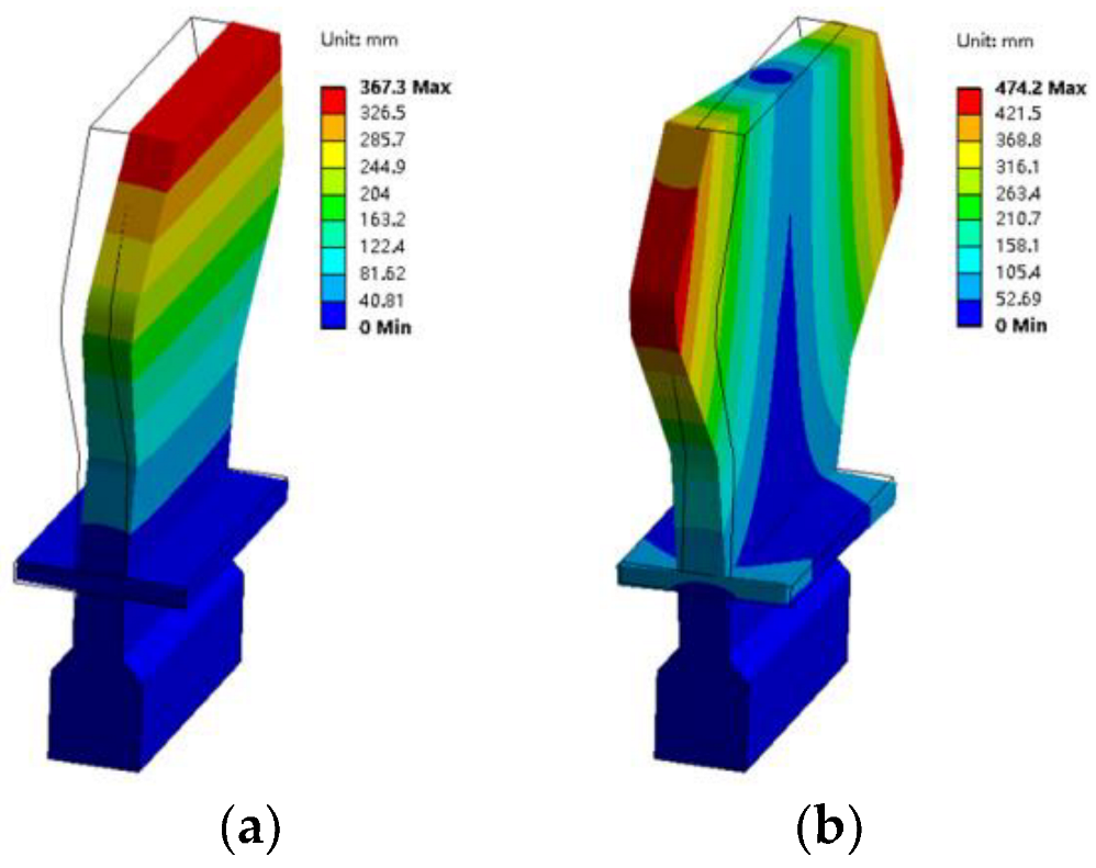
This calculation mainly focused on the vibration mode of the blade and the nonlinear friction damping effect of the UPDs. To improve the computational efficiency, the structure of the blade tenon and the overly complicated platform were simplified in the model, and the UPDs were simplified to rectangular solids. This simplification ensured that the resonant frequency and the vibration stress position of the simplified blade’s torsional vibration were essentially the same as the measured blade. The design requirements for the blades will be described in Section 3.2 in conjunction with the experiments. The first-order bending and torsional vibration modes of the test blade are shown in Figure 2. For the convenience of experimental measurements, the special design of the leaf shape brought the positions of the maximum vibration strain of the first-order bending vibration and torsional vibration closer together.

2.1.2. Motion Equations

The vibration problem of the multi-blade system with UPDs satisfies the second-order ordinary differential equations:
M q ¨ + D q ˙ + K q + f nl ( q , q ˙ , t ) = f ex ( t ) .
Herein, q, fnl, and fex   Rd×1 are the vectors of the generalized coordinates, nonlinear, and external generalized forces, respectively. d is the number of degrees of freedom (DOF), and M, D, and K   Rd×d are constant coefficient matrices associated with the acceleration, velocity, and displacement proportional forces, which also called mass, damping, and stiffness matrices.
To obtain the coefficients M, D, and K, the pre-stress modal analyses were carried out using the finite element method (FEM). The followings are the main steps:
  • Firstly, the model of a multi-blade system with UPDs was meshed with a solid hexahedral eight-node element, as shown in Figure 3.
  • The influence of centrifugal load was taken into account in the static structural analysis. In the static structural calculation, the blade tenons were constrained in all directions and the contact parts of the UPDs and blades were treated as frictionless contacts. Only the influence of normal force was considered. The system had a constant rotational speed, which generated centrifugal force. The stress of the multi-blade system with UPDs under rotation and the contact state and normal stiffness between the blade and UPDs were obtained.
  • Then, the modal analyses with pre-stress were performed. The results of the static structural analyses were used as the pre-stress for modal analyses so that the constant coefficient matrices of the multi-blade system with UPDs could be obtained.
fex is the external generalized force, which is arranged by the forces fi on each node in order of node number as fex = [f1; …; fi; …; fmax]. Herein, fi   R3×1 and max is the maximum node number. For blade vibration response problems, the external excitation force is the periodic sinusoidal force, which is also linear. The excitation force on adjacent blades has a phase difference equal to the blade-to-blade angle α0. The excitation force acting on the rotating blade can be represented as a concentrated tangential force at the leading edge of the blade near the blade tip, and the amplitude of the excitation force F0 can be approximated to be the same for all blades. Thus, the excitation force fi for each node can be expressed in generalized global coordinate as:
f i = F 0 sin ( ω t + j α 0 ) sin ( j α 0 ) F 0 sin ( ω t + j α 0 ) cos ( j α 0 ) 0   δ ( i , l j )   j   =   2 ,   1 ,   0 ,   1 ,   2 .
Herein, j denotes the number of the blade in order from left to right, lj is the node number of the j-numbered blade load node, and δ is the Kronecker Delta function, which satisfies:
δ ( i , l j ) = 1 i = l j 0 i l j .
fnl is the nonlinear internal force. In the blade-damper system, only the frictions between the blade platforms and the UPDs were considered. The elastic Coulomb friction was used in this study. The hysteretic character of the tangential force ft is governed by the following differential equation [14]:
d f t = k t d q t f t + k t d q t μ f n   sticking   0 f t + k t d q t > μ f n   sliding   .
Herein, qt is the tangential displacement between the two contact points, μ is the friction coefficient, fn is the normal force, which is mainly provided by centrifugal force, and kt is the scalar tangential stiffness per area value. The tangential contact stiffness kt can be estimated roughly [38,39] from:
k t = 2 ( 1 υ D ) ( 2 υ D ) k n ,
where kn is the normal stiffness and υD is the Poisson’s ratio of the damper. Due to the different forces and contact states, different contact point pairs have different normal stiffnesses. kn could be extracted from the stiffness matrix K by determining the number of nodes of each contact point pair. This could obtain the kt of all the contact point pairs. The steps for establishing the nonlinear motion equations are shown in Figure 4.

2.2. Numerical Solution of the Nonlinear Motion Equations

In the previous section, the motion equation of the multi-blade system with UPDs was established, and several key matrices of the motion equation were obtained. For the forced vibration response problem, it is desired to obtain the steady-state response amplitude of the multi-blade system with dampers at different frequencies and connect them into frequency domain response curves. In this section, the equations of motion are transformed by the HBM, and the nonlinear equations are solved using the Newton method. The computational methods are briefly described in this section, while the detailed derivations and proofs can be found in book [40].

2.2.1. The Harmonic Balance Method

The harmonic balance method is a Galerkin method with harmonic base functions, which is well suited for the computation of periodic solutions of ordinary differential equations. The generalized coordinates q(t) are approximated as qh(t), which can be expanded in a truncated Fourier series:
q ( t ) q h ( t ) = n = 0 n h Q n e i n Ω t ,
where n are the harmonic indices and nh is the specified harmonic order considered, which is called the harmonic truncation order. Ω is the fundamental vibration frequency and Qn are the complex-valued amplitudes.
The deviation between the approximate qh(t) and exact solution q(t) is called the error. The residual rh(t,{Qn}) depends on the time t and the sought coefficients Q1,…, Qnh. According to Galerkin ideas, this error term should not have a component in the subspace spanned by the base functions. The weighted residual approach [37] could be used by making the residual orthogonal to the weight functions ρj, in which the base functions also act as weight functions and satisfy the following:
1 T 0 T ρ j ( t ) r h t , Q k d t = ρ j , r h = 0 j = 1 , , n h .
When all the terms in the equations of motion Equation (1) are represented by truncated Fourier series, the Fourier coefficients of the residual R could be described as a set of nonlinear algebraic equations in the unknown Fourier coefficients:
R = [ ( n Ω ) 2 M + i n Ω D + K ] S n ( Ω )   Q n + F nl ( Q 0 , , Q n h , Ω ) F ex ( Ω ) = 0 .
where Sn is the dynamic stiffness matrix with regard to the n-th harmonic and Fnl and Fex are the complex amplitudes of fnl and fex from the Fourier transform. Both Sn and Fex in the above equation are linear, and their Fourier coefficients can be obtained more directly. However, the harmonics of the nonlinear forces Fnl need to be expressed as a function of Q by alternating the frequency–time (AFT) [41]:
F n l = DFT f n l iDFT Q 0 , , Q n h ,
where (i)DFT denotes the (inverse) discrete Fourier transform. The elastic Coulomb friction equation shown in Equation (4) can be transformed by Equation (9) to F nl ( Q 0 , , Q n h , Ω ) .

2.2.2. The Newton Method

Equation (6) obtained in the previous section can be simply written as:
R ( x ) = 0 ,
where R is the residual function and x is the vector of unknowns. The Newton method [42] is a very popular local method for the iterative solution of nonlinear algebraic equations. The idea is to expand the residual in a Taylor series around the current estimate x(j) and determine the next estimate x(j+1) as the solution of the linearized problem:
R x ( j + 1 ) R x ( j ) + R x x ( j ) x ( j + 1 ) x ( j ) = 0
R x x ( j ) x ( j + 1 ) x ( j ) = R x ( j ) ,
where the matrix R / x = R i / x j is the Jacobian matrix, which contains the partial derivatives of the residual with respect to the unknowns.
Combined with the above contents, we developed a MATLAB program to solve the nonlinear vibration response problems with friction. The computational procedure primarily consisted of the following steps:
  • Input the constants and matrices needed for the computation, such as the matrices obtained in Section 2.1, the mass of the UPDs, the rotational speed, excitation force, minimum calculation frequency f1, maximum calculation frequency f2, and node numbers for frictional force.
  • Construct the excitation force vector fex, frictional force element fnl, and then the motion equation, as shown in Equation (1).
  • Compute the blade’s vibration response without considering fnl.
  • Construct the Fourier coefficient equations of the residual R in Equation (8) using the HBM and employ the ‘fsolve’ function to find an approximate solution at f1, which serves as the initial guess for the nonlinear equations.
  • Employ the Newton method to solve the nonlinear Equation (10) within the frequency range of f1~f2. The convergence tolerance was set at 10−7. The computation adjusted the step size using the arc-length continuation method, increasing the step size at easily converging points to improve computational efficiency and decreasing the step size at difficult converging points to ensure converged solutions were obtained.
  • Complete all the calculations within the frequency range and save the calculated data.
This paper does not discuss some details of the computational processing methods, such as the path continuation to calculate branch points and how to obtain a good initial value guess for convergence. These topics are not the focus of this study. Readers who are interested in these methods can refer to the book [37].

2.3. Numerical Results

2.3.1. Modal Vibration of Multi-Blades System with Dampers

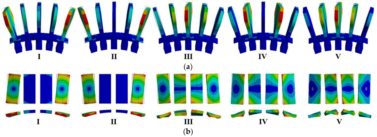
In order to obtain the contact status, vibration modes, mass, and stiffness matrices of the system, finite element modal analysis was performed on the multi-blade system with UPDs. Only centrifugal loads were considered for system prestress. To obtain the normal contact stiffness, the contacts between the blade and dampers were assumed to be frictionless. The rotational velocity of 22,070 r/min was determined based on the calculation of torsional vibration resonance speed. Its specific value will be determined in Section 3.3. The modal analysis showed the first ten mode frequencies and shapes of the multi-blade system with UPDs. The first five modes were the first-order bending vibration modes, while the sixth to tenth modes were the first-order torsional vibration modes. Five different torsional vibration mode blade shapes and UPDs are listed in Figure 5. The first two modes are mainly the torsional vibration of the two blades on both sides with different vibratory phases, and their vibration frequencies are lower (i.e., 5155.9 Hz and 5156.2 Hz) because the two blades lack the constraint of the outer UPDs. The latter three modes have higher frequencies (i.e., 5162.9 Hz, 5169.1 Hz, and 5174.9 Hz), as the central three blades are constrained by the two side UPDs, and all four UPDs participate in the vibration. The three modes have different modal frequencies due to the existence of the UPDs, with phase differences in blade vibration.
Based on the results of the modal analysis with frictionless contacts, the torsional modal (I~V) frequencies of the system existed at a 19 Hz difference due to the UPDs’ normal stiffness under only the centrifugal load. Among the central blade’s three torsional vibration modes (I, II, IV), almost no vibration was observed. Therefore, if the central blade was set as the test blade, two vibration peaks (III, V) would be detected. In subsequent calculations, the tangential contact stiffness brought about by the friction of the contact surfaces must be taken into account. The presence of friction will alter the vibration phase difference between the adjacent blades, the frequency of each mode, and significantly increase the frequency difference between different modes.

2.3.2. The Impact of Harmonic Truncation Order nh on the Solution of Nonlinear Vibrations

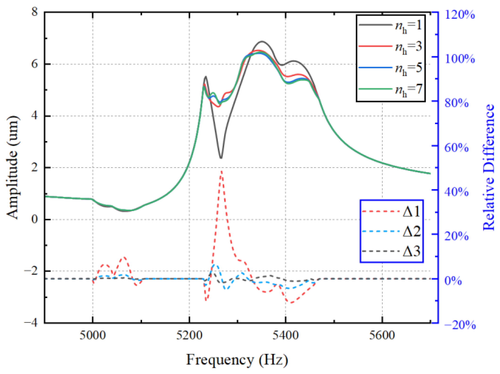
The impact of harmonic truncation order on the solution of nonlinear vibrations was discussed. After the system’s constant coefficient matrices were obtained from modal analysis, the nodes on the contact surface of the blade and UPDs were connected by friction units, and the nonlinear friction force was processed by the HBM. Finally, the vibration response of the system was obtained by solving the motion equations. In the above steps, the harmonic truncation order nh has a significant impact on the accuracy of the calculation results. For a system with d degrees of freedom, the number of equations to be solved is (2 × nh + 1) × d, which means that an increase in harmonic truncation order will greatly increase the number of equations to be solved and reduce the calculation efficiency. However, the higher the harmonic truncation order, the higher the calculation accuracy. For bending vibrations, it is commonly believed that the accuracy with nh = 1 can meet the calculation requirements, but for torsional vibrations, it is difficult for the first harmonic to meet the calculation accuracy requirements. Therefore, we first compared the calculation results of the same calculation inputs for four cases of harmonic truncation orders nh = 1, 3, 5, 7, and the circumferential displacement responses of the tip vertex of the central blade were output as shown in Figure 6. The differences Δ in the adjacent nh calculation results were also plotted in the figure. By comparison, it was found that the vibration response exhibited significant deviations for nh = 1 compared to other truncation orders, with a maximum deviation of up to 44%, whereas the deviations were small (<5%) for nh = 3 to nh = 5 or nh = 7. Therefore, based on the calculation results, computation time, efficiency, and accuracy, the harmonic truncation order nh was determined to be 3 for subsequent calculations.

2.3.3. Effect of Normal Force Caused by UPDs

The impact of UPDs on the blade vibration response under different normal forces can be calculated by taking into account the contact surface normal force, which primarily depends on the rotating speed and the mass of the UPDs. With a fixed engine speed, the main factor affecting the normal force is the mass of the UPDs. However, due to limited installation space, the volume and mass of UPDs are typically small compared to the blade. The variation in normal force mainly affects two aspects: first, the pre-stress of the blades, which has a limited impact due to the mass of the UPD, which is only 1/70th of the blade mass. The second aspect is the impact on the friction state, which determines the friction and motion state between the blade and UPDs and greatly affects the system’s vibration response. Therefore, the study of the effect of different masses of UPDs on the vibration response of a multi-blade system with dampers under the same rotating speed and excitation force was carried out. The vibration response curves were plotted by taking the circumferential vibration displacement of the vertex at the tip of the central blade with UPDs of different masses, as shown in Figure 7. Here, m0 represents the mass of one of the UPDs, while the experimental blade mass mb was 70 times of m0. Five scenarios were considered, where the mass of the UPDs were 0.5 m0, 1.0 m0, 1.5 m0, 2.0 m0, and 4.0 m0. The undamped response curve was obtained from a single-blade harmonic response analysis in which the damping ratio was set to 0.2%, as established in previous experiments [33]. This damping ratio was mainly material damping, and the same damping ratio was set in the calculation for all the conditions.
From the vibration response curve, it can be observed that when the UPD mass is relatively small (0.5 m0 and 1.0 m0), the response of each mode of the central blade only has one significant main peak and one smaller peak fluctuation, and the response amplitudes are smaller compared to those without dampers. As the UPD mass increases, the peak amplitudes of blade response increase, and there are three similar peak amplitudes (1.5 m0). As the UPD mass continues to increase (2.0 m0 and 4.0 m0), the peaks on both sides increase, and the central peak decreases, as pointed by the red arrows in the figure. If the mass continues to increase, the response curve has almost no change, which means that all the contacts are in a sticky state. In this state, the effect of friction damping is limited, and it cannot effectively reduce blade vibration accompanied by the increase in overall weight, leading to uneconomical outcomes. In practical applications, in order to improve the HCF life of the blade, it is necessary to minimize the blades’ vibration amplitude and reduce the possibility of peak occurrences. The installation of UPDs can not only adjust the resonant frequencies but also alter the torsional vibration response amplitudes of blades. However, in order to achieve a better damping effect, the selection of UPD mass or contact surface normal force must be carefully considered.

3. Excitation Experiments with a Spin Tester

3.1. Description of the Test Equipment

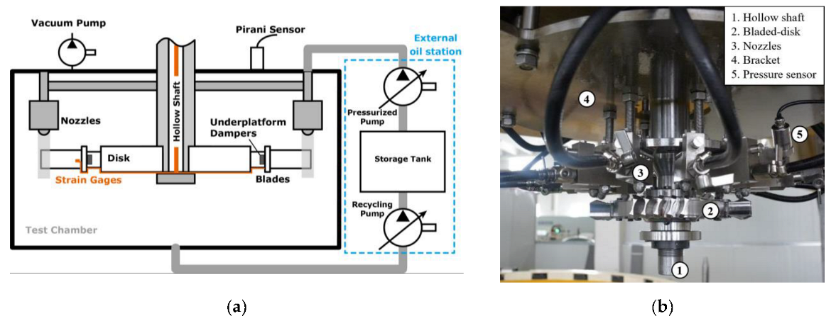
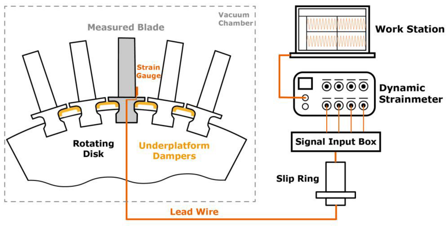
In order to verify the vibration reduction effect of UPDs on blade torsional vibration experimentally, a vibration excitation system based on a high-speed vertical spin tester was designed to conduct forced vibration tests on blades under high-speed rotation, as shown in Figure 8. A certain number of nozzles were placed above the blade in the circumferential direction on the basis of a vertical spin tester. The conical liquid column ejected from the nozzles was used to simulate the airflow after passing through the stationary blade. The liquid impacted the high-speed rotating blades to achieve the forced vibration of the blade. The blade’s vibration response was collected using strain gauges attached to the surface of the blade, and the strain signals were transmitted to a dynamic strain meter in real time through the slip ring and signal input box for acquisition and analysis. The excitation frequency f (Hz) in the experiment was determined by the blade rotating speed nrot (r/min−1) and the number of nozzles N, which satisfies f = N × nrot/60. When the excitation frequency is close to the resonance frequency of a certain mode of the blade, the blade vibration response will increase significantly, and resonance will occur. In the experiment, when the number of nozzles N was fixed, the sweep frequency measurement could be achieved by adjusting the rotating speed within a larger excitation frequency range. When there was a speed range requirement for the test, the excitation frequency could also be adjusted by changing the number of nozzles. The main components and specifications of the experimental setup are as follows:
  • Vertical spin tester: The tester driven by the motor and pulley can perform controlled high-speed spin tests. During the test, the test chamber was kept in a vacuum state (pressure < 2 Torr) to avoid the influence of excessive airflow on the test results.
  • External oil station: The supply and return oil of the spray excitation system are realized through an external oil station arranged outside the test chamber. Aviation lubricating oil is selected as the liquid for spraying, which can maintain a liquid state in an almost vacuum environment. The external oil station can pressurize and transport the oil outside the test chamber to the nozzle inside the test chamber. The supply pressure can be adjusted as required, and the maximum supply pressure is 1.0 MPa. The maximum pressure at the nozzle will have certain attenuation based on factors such as height, number of nozzles, and pipe length, generally ranging from 0.8 MPa to 0.85 MPa. In addition, components for oil recovery and filtration are installed in the test chamber to recycle and filter the liquid that has been sprayed out.
  • Nozzles and bracket: The fuel injection nozzles were used in the experiment, which could produce a hollow conical shape under standard pressure. The flow rate Q of the nozzle is related to the pressure P at the nozzle and satisfies the equation:
    Q Q st = P P s t ,
    where Pst is the nominal standard pressure of the nozzle, and Qst is the flow rate of the nozzle corresponding to Pst pressure. The total number and installation position of the nozzles can be adjusted as needed. The number of nozzles is designed according to the size, speed, and vibration frequency of the test requirements. The installation height, radius, and angle of the nozzle can all be adjusted according to the test requirements.
  • Vibration signal acquisition system: The vibration information of the blades is obtained using strain gauges attached to the blade surface and transmitted to the top of the hollow shaft and high-speed slip ring through lead wires. The rotating signal is transmitted through the slip ring to the signal input box, which is connected to a dynamic strain meter. The vibration signals will be collected and stored in the dynamic strain meter. Finally, the dynamic strain meter is connected to a work station to achieve real-time display and analysis blade vibration signals, as shown in Figure 9. The strain gauges used were normal temperature single-axis strain gauges with the model number BE120-1AA, having a resistance of 120Ω and a grid length of 1 mm. The high-speed slip ring allowed a maximum rotational speed of 50,000 r/min, encompassing 16 channels. The rotating signals can be converted into non-rotating signals by the slip ring, facilitating the transmission of signals for data acquisition outside the test chamber. The dynamic strain meter comprised eight acquisition channels, with each individual channel’s sampling frequency set at 20,480 Hz.

3.2. Design of the Multi-Blade System with UPDs

The design of the test rotor included five adjacent test blades installed on a dummy disc and UPDs installed between adjacent blades. The test blade design satisfied the following requirements:
  • The test blade needs a platform that can install UPDs. The mortise and tenon joints were fir-tree-shaped to meet the strength requirements under high speeds. Additionally, it is crucial to ensure that there is enough normal pressure on the blade tenon contact surfaces in the vicinity of the test speed, with most of the contact surfaces in a stick state. In the stick state, the frictional force provided by the tenon joint contact surface is limited, which can reduce the impact of tenon joint friction on blade vibration.
  • The first-order bending and torsional vibration mode of the blade should be independent to each other, and the frequencies of the torsional vibration mode should be within the excitation range of the test equipment. According to the modal analysis results of the pre-stressed blade, the bending vibration frequency of the blade at a speed of 25,000 r/min is approximately 2350 Hz, and the torsional vibration frequency is approximately 5160 Hz. The two modal frequencies are significantly different, and there is no multiple relationship between them.
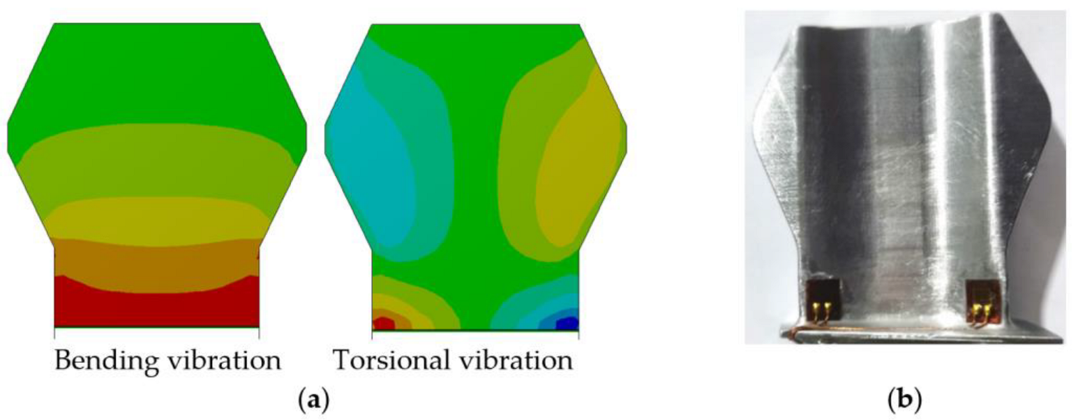
  • The blade body has clear positions of torsional vibration stress concentration, which are relatively flat and easy to position strain gauges. The test blade shape is axially symmetrical, with almost identical vibrational strains at two locations where strain gauges can be attached to prevent signal loss due to gauge or wire breakage. The special blade shape design will not affect the vibration mode of the UPDs or the first-order bending and torsional vibration of the blade body. The radial vibration strain distributions of the blade body for first-order bending and torsional vibration obtained from the finite element modal analysis is shown in Figure 10a. The strain gauges were attached at locations with relatively large vibration strains, as in Figure 10b.
The UPDs were designed to be box-shaped and installed underneath the adjacent blades’ platform to dissipate the vibration energy, as shown in Figure 11. Three different UPDs with varying masses, 0.5 m0, 1.0 m0, and 2.0 m0, were designed and fabricated using metal 3D printing, with the same contact surface as the blade platform. The UPDs’ mass was adjusted by varying the thickness of the dampers.

3.3. Number of Nozzles Determined

As mentioned earlier, the experimental rotating speed and nozzle number are crucial for the success of the excitation tests. The bending and torsional vibration frequencies were calculated using a modal analysis with pre-stress at each speed and plotted with different nozzle numbers in Figure 12. The results of the static analysis of the blade mechanics showed that the blade would start to yield extensively at 25,000 r/min, so the upper limit of the experimental speed was set to 25,000 r/min. The figure shows that the frequency lines of multiple nozzle numbers intersect with the red line of the torsional vibration frequency. The intersection point of the highest rotational speed was 13 nozzles, but a frequency margin was needed, as the frequency will increase after the installation of UPDs. Therefore, the final selection was N = 14 nozzles, and the intersection speed was 22,070 r/min.

3.4. Brief Description of Experimental Steps

The experimental setup involved four different conditions for the multi-blade system, without dampers and with UPDs of three different masses. To perform these experiments, the test rotor needed to be prepared, along with the spray-excited vibration system, vertical spin tester, and dynamic signal acquisition system. Before the formal tests, it was necessary to confirm the above parts were working properly and complete some necessary calibration tests.
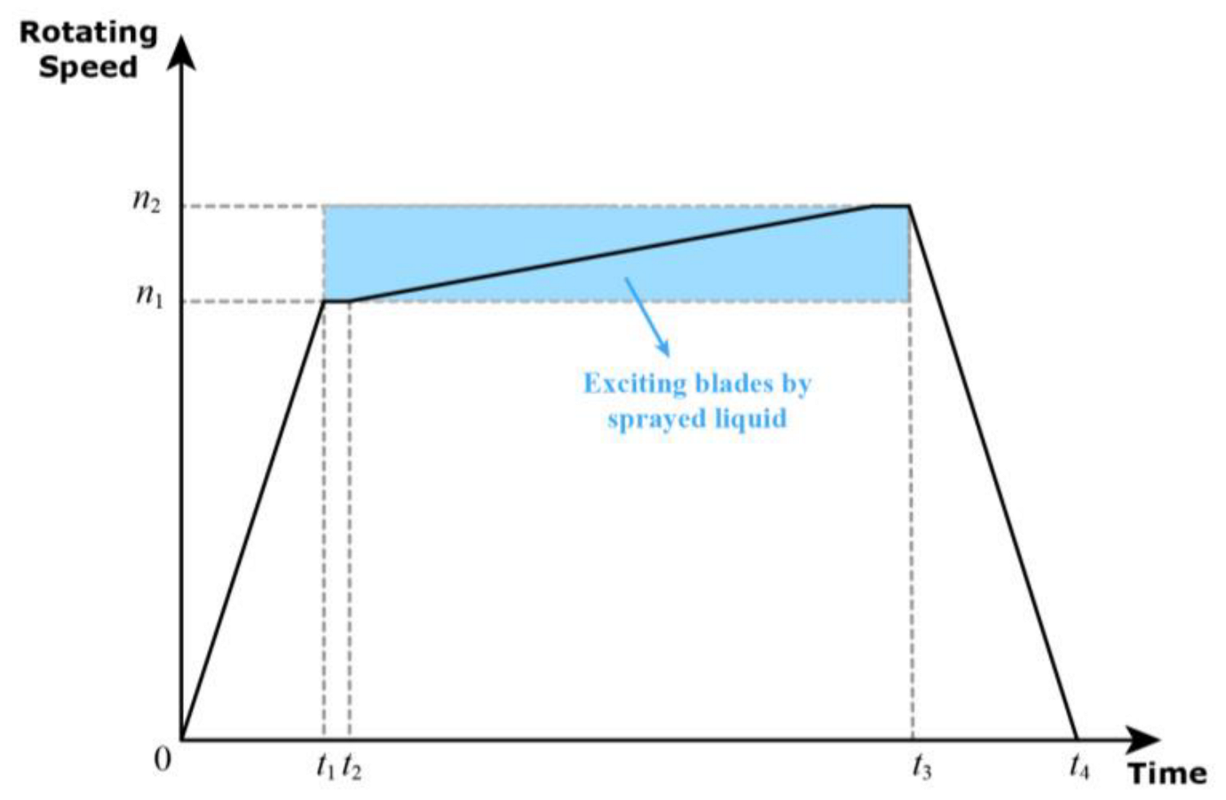
Formal testing comprised two parts: frequency sweep tests and vibration response measurements. The frequency sweep tests were conducted to identify the blade resonance speed with faster acceleration in a broader speed range. Following that, the vibration response measurements were performed to obtain blade vibration response curves within the speed range of n1~n2 (in Figure 13) around the blade resonance speed with a lower acceleration. In the previous section, the predicted resonance speed of a single blade’s torsional vibration was obtained, while the simulation calculation results showed that the multi-blade system with UPDs would have a complex response over a range of frequencies (at least 300 Hz). Therefore, the range of excitation speeds for the vibration response measurements needed to be determined based on the sweep test results and simulation calculation results. In the experiments of this study, the initial excitation speed n1 was 21,500 r/min, and the maximum excitation speed n2 was 24,000 r/min. During the test, the test rotor was accelerated from standstill to n1, then the rotating speed was kept stable during the time from t1 to t2. During this period, the oil pump of the external oil station was activated, and the pressure at the nozzles was allowed to stabilize. After that, the rotating speed continued to increase slowly by maintaining the excitation. The strain data were collected at the same time until the rotating speed reached n2 at t3, and finally, the tester was slowed down to a stop. Disassembly and reinstallation of the blades and UPDs were required between four different installation configurations.

3.5. Experimental Results and Analysis

3.5.1. Liquid Spray Exciting Experimental Results

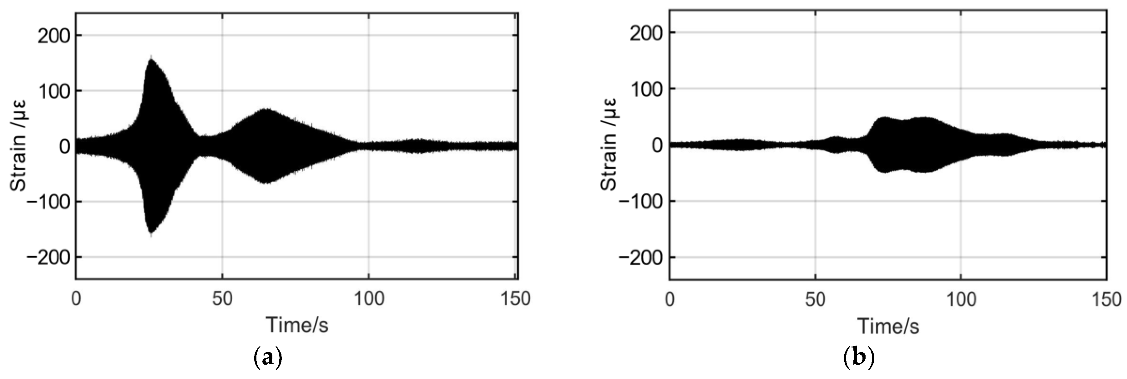
Four tests were conducted to obtain the forced torsional vibration strain signals of the rotating blades under four different conditions: no UPDs installed and UPDs with masses of 0.5 m0, 1.0 m0, and 2.0 m0. However, the complete signal contained static strain due to the centrifugal load and circuit interference, and thus the strain signal needed to be processed. The time-domain signals of the vibration strains were obtained by extracting the parts of the original signals with significant resonance responses during the acceleration and processing them with bandpass filtering. Figure 14 shows the time-domain signals of the vibration strains for each of the four conditions.
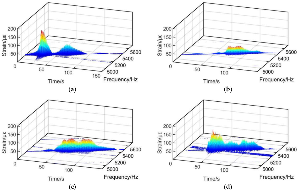
From the time-domain signals, it is evident that the response of the multi-blade system with UPDs varied significantly with different installation configurations. To obtain a more intuitive understanding of its forced vibration response at different excitation frequencies, the above signals were subjected to a time–frequency analysis. The time–domain signals were divided into multiple segments of length Nf = 10,240, and FFT processing was performed on each segment. The frequency resolution was 2 Hz. Finally, the resulting waterfall plots were shown in Figure 15.

3.5.2. Comparison and Discussion between Experimental and Numerical Results

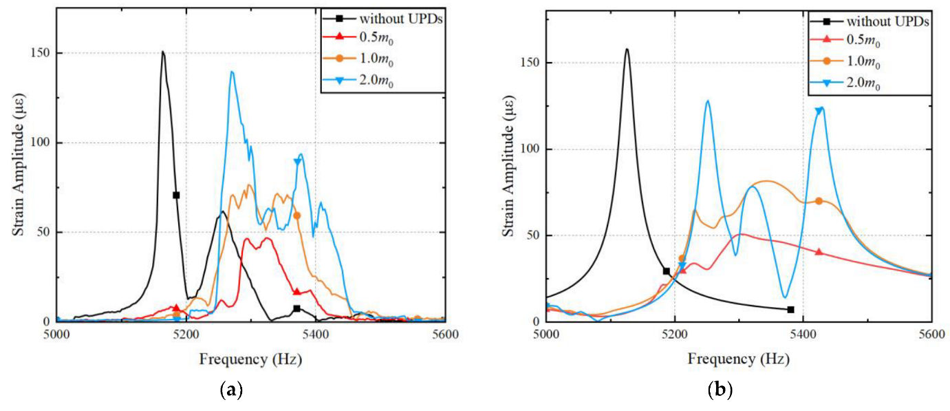
The time–domain signals and waterfall plots illustrate that the forced vibration response of the multi-blade system with UPDs varied significantly with different installation configurations. When no UPDs were installed, a clear resonance peak occurred at 5163 Hz, with a peak amplitude exceeding 150 με and a small resonance frequency span of approximately 60 Hz. After the UPDs were installed, the peak amplitudes of the response decreased, the resonance frequencies increased, and multiple peaks appeared, accompanied by increases in the resonance frequency span correspondingly. When the UPD mass was 0.5 m0, the vibration response could be approximately considered as having one peak. When the UPD mass was 1.0 m0, the vibration response changed smoothly and could be approximately considered as having two peaks. When the UPD mass was 2.0 m0, the vibration response had large fluctuations and had three peaks. The peak values of each section of the waterfall plot were extracted and plotted in an amplitude–frequency response curve in Figure 16a for comparison.
A comparison with the numerical simulation results was also conducted. The circumferential displacement of the vertex of the central blade tip in the numerical simulation results was converted into the radial strain at the position of the strain gauges according to the modal analysis. The vibration response curve of the numerical simulation results was plotted in Figure 16b. By comparing the frequency domain curves obtained from the experiments and numerical simulations, multiple peaks were found in the vibration response of the blade as the UPD mass increased. The curves of the numerical and experimental results were similar but not perfectly matched. For example, in the situation without dampers, there was a small peak near the maximum amplitude peak, which did not appear in the numerical results. This phenomenon might be attributed to the vibration response transfer due to the imperfect frequency matching between adjacent blades. In numerical simulations, we ideally assumed that the vibrations of each blade were independent and not influenced by other blades under undamped conditions. However, in the excitation experiments, the blades were not completely independent, and exist vibration transfer might have existed between adjacent blades. Additionally, the blade frequencies in the experiments had slight differences due to manufacturing and assembly errors. Therefore, the blade responses obtained from the excitation experiments without dampers and with UPDs showed slight discrepancies compared to the numerical simulation results. Nonetheless, the trend in the main peak variation was similar to that of the numerical simulation results.
Table 1 lists the numerical and experimental results for the resonance frequency and their increased ratio of rotating blades with UPDs compared to those without UPDs. Table 2 lists the numerical and experimental results for the resonance amplitude and their reduction ratio of rotating blades with UPDs compared to those without UPDs. The maximum vibration response peak value and corresponding frequency were used for comparison. The data in the tables indicates that the installation of UPDs increases the resonant frequencies of blade torsional vibration, decreases the amplitudes of the resonant peak. With 0.5 m0 UPDs installed, the peak value decreased by 68.9% and the resonant frequency increased by 3.1%. This indicates that the UPDs had a good frequency tuning and vibration reduction effect on the forced torsional vibration of the rotating blades. The numerical calculation results are similar to the experimental results in terms of the change in resonant frequency and peak value after the installation of UPDs, indicating that the numerical calculation method can accurately predict the forced torsional vibration response of rotating blades with UPDs installed.

4. Conclusions

This study investigated the influence of UPDs on the forced torsional vibration response of a multi-blade system under rotation using both numerical simulations and excitation experiments. Nonlinear equations were constructed by combining a friction model and a pre-stressed modal analysis. The model also took into account the effects of the centrifugal load and the UPDs’ normal force. The harmonic balance method was used to handle the nonlinear friction force and solve the forced vibration response of blades with different masses of UPDs. In addition, forced vibration tests were conducted on a vertical spin tester using the impact of spray liquid on high-speed rotating blades to generate excitation forces. Blades without UPDs and with different masses of UPDs were tested. The excitation experiments successfully induced rotating multi-blade system resonance near the predicted torsional resonance frequency. Strain signals of the blades near the resonant frequencies were obtained. Comparing the numerical simulation and experimental results, the following conclusions were obtained:
  • The UPDs turned the multiple independently vibrating blades into a multi-blade system. In both the numerical and experimental results, blades with UPDs showed multiple peaks and higher resonance frequencies in their forced vibration response compared to those without dampers, and they were varied with the mass of UPDs.
  • Properly selected masses of UPDs led to effective reduction of blade torsional vibration, with a 68.9% reduction in resonance amplitude achieved with 0.5 m0 UPDs. However, excessively high normal force or UPD mass could increase blade torsional vibration response and lead to multiple large peaks, emphasizing the importance of careful selection during the design phase.
  • The numerical method used to predict forced torsional vibration response of rotating multi-blade systems with UPDs showed relatively close agreement with the experimental results, indicating its effectiveness in predicting the nonlinear response of multi-blade systems and providing a design reference for blades and UPDs.

Author Contributions

Conceptualization, Y.W. and H.X.; funding acquisition, C.W. and D.M.; investigation, Y.W. and H.X.; methodology, Y.W.; resources, M.Q. and T.J.; software, Y.W.; supervision, D.M. and T.J.; validation, C.W. and M.Q.; writing—original draft, Y.W.; writing—review and editing, H.X. All authors have read and agreed to the published version of the manuscript.

Funding

This research was funded by the Chinese Double First-Class Initiative Special Fund (2018-Ⅱ-0014-0023) and the research fund of the AECC Hunan Aviation Powerplant Research Institute (KY-44-2018-0517).

Data Availability Statement

The data are not publicly available due to privacy.

Acknowledgments

The authors acknowledge Malte Krack and Johann Gross for their open-source Matlab tool (NLvib), which provided extremely important guidance and learning materials in the early stages of this study.

Conflicts of Interest

The authors declare no conflict of interest.

References

  1. Ewins, D.J. Control of Vibration and Resonance in Aero Engines and Rotating Machinery—An Overview. Int. J. Press. Vessel. Pip. 2010, 87, 504–510. [Google Scholar] [CrossRef]
  2. Griffin, J.H. A Review of Friction Damping of Turbine Blade Vibration. Int. J. Turbo Jet Engines 1990, 7, 297–308. [Google Scholar] [CrossRef]
  3. Zhu, Y.; Wang, Y.; Qiao, B.; Fu, S.; Liu, M.; Luo, X.; Chen, X. Full-Field Dynamic Strain Reconstruction of Rotor Blades under Multi-Mode Vibration. Measurement 2022, 201, 111670. [Google Scholar] [CrossRef]
  4. Earles, S.W.E.; Williams, E.J. A Linearized Analysis for Frictionally Damped Systems. J. Sound Vib. 1972, 24, 445–458. [Google Scholar] [CrossRef]
  5. Griffin, J.H. Friction Damping of Resonant Stresses in Gas Turbine Engine Airfoils. J. Eng. Power 1980, 102, 329–333. [Google Scholar] [CrossRef]
  6. Cameron, T.M.; Griffin, J.H.; Kielb, R.E.; Hoosac, T.M. An Integrated Approach for Friction Damper Design. J. Vib. Acoust. 1990, 112, 175–182. [Google Scholar] [CrossRef]
  7. Panning, L.; Sextro, W.; Popp, K. Spatial Dynamics of Tuned and Mistuned Bladed Disks with Cylindrical and Wedge-Shaped Friction Dampers. Int. J. Rotat. Mach. 2003, 9, 219–228. [Google Scholar] [CrossRef]
  8. Cigeroglu, E.; An, N.; Menq, C.-H. A Microslip Friction Model with Normal Load Variation Induced by Normal Motion. Nonlin. Dyn. 2007, 50, 609–626. [Google Scholar] [CrossRef]
  9. Allara, M. A Model for the Characterization of Friction Contacts in Turbine Blades. J. Sound Vib. 2009, 320, 527–544. [Google Scholar] [CrossRef]
  10. Gastaldi, C.; Gola, M.M. On the Relevance of a Microslip Contact Model for Under-Platform Dampers. Int. J. Mech. Sci. 2016, 115, 145–156. [Google Scholar] [CrossRef]
  11. Yudi, C.; Yanrong, W. A Method for the Resonant Response Evaluation of Blades System with Underplatform Dampers. Vibroeng. Procedia 2014, 4, 164–169. [Google Scholar]
  12. Pesaresi, L.; Armand, J.; Schwingshackl, C.W.; Salles, L.; Wong, C. An Advanced Underplatform Damper Modelling Approach Based on a Microslip Contact Model. J. Sound Vib. 2018, 436, 327–340. [Google Scholar] [CrossRef]
  13. Li, D.; Botto, D.; Xu, C.; Liu, T.; Gola, M. A Micro-Slip Friction Modeling Approach and Its Application in Underplatform Damper Kinematics. Int. J. Mech. Sci. 2019, 161–162, 105029. [Google Scholar] [CrossRef]
  14. Krack, M.; Salles, L.; Thouverez, F. Vibration Prediction of Bladed Disks Coupled by Friction Joints. Arch. Comput. Methods Eng. 2017, 24, 589–636. [Google Scholar] [CrossRef]
  15. Phadke, R.; Berger, E.J. Friction damping analysis in turbine blades using a user-programmed function in Ansys; Paper ISROMAC12-2008-20176. In Proceedings of the 12th International Symposium on Transport Phenomena and Dynamics of Rotating Machinery, Honolulu, HI, USA, 17–22 February 2008. [Google Scholar]
  16. Urabe, M. Galerkin’s Procedure for Nonlinear Periodic Systems. Arch. Ration. Mech. Anal. 1965, 20, 120–152. [Google Scholar] [CrossRef]
  17. Zucca, S.; Firrone, C.M. Nonlinear Dynamics of Mechanical Systems with Friction Contacts: Coupled Static and Dynamic Multi-Harmonic Balance Method and Multiple Solutions. J. Sound Vib. 2014, 333, 916–926. [Google Scholar] [CrossRef]
  18. Gastaldi, C.; Berruti, T.M. A Method to Solve the Efficiency-Accuracy Trade-off of Multi-Harmonic Balance Calculation of Structures with Friction Contacts. Int. J. Non-Linear Mech. 2017, 92, 25–40. [Google Scholar] [CrossRef]
  19. Liu, T.; Zhang, D.; Xie, Y. A Nonlinear Vibration Analysis of Forced Response for a Bladed-Disk with Dry Friction Dampers. J. Low Freq. Noise Vib. Act. Control 2019, 38, 1522–1539. [Google Scholar] [CrossRef]
  20. Kwon, S.; Chung, J.; Yoo, H.H. Transient Vibration Characteristics of a Rotating Multi-Packet Blade System Excited by Multiple Nozzle Forces. Int. J. Mech. Sci. 2014, 83, 76–90. [Google Scholar] [CrossRef]
  21. Sever, I.A.; Petrov, E.P.; Ewins, D.J. Experimental and Numerical Investigation of Rotating Bladed Disk Forced Response Using Underplatform Friction Dampers. J. Eng. Gas Turbines Power 2008, 130, 042503. [Google Scholar] [CrossRef]
  22. Szwedowicz, J.; Gibert, C.; Sommer, T.P.; Kellerer, R. Numerical and Experimental Damping Assessment of a Thin-Walled Friction Damper in the Rotating Setup with High Pressure Turbine Blades. J. Eng. Gas Turbines Power Trans. ASME 2008, 130, 012502. [Google Scholar] [CrossRef]
  23. Armstrong, E.K. Recent Blade Vibration Techniques. J. Eng. Power 1967, 89, 437–444. [Google Scholar] [CrossRef]
  24. Peters, W.H.; Ranson, W.F. Digital Imaging Techniques in Experimental Stress Analysis. Opt. Eng. 1982, 21, 427–431. [Google Scholar] [CrossRef]
  25. Stanbridge, A.B.; Ewins, D.J. Modal Testing Using a Scanning Laser Doppler Vibrometer. Mech. Syst. Signal Process. 1999, 13, 255–270. [Google Scholar] [CrossRef]
  26. Zucca, S.; Di Maio, D.; Ewins, D.J. Measuring the Performance of Underplatform Dampers for Turbine Blades by Rotating Laser Doppler Vibrometer. Mech. Syst. Signal Process. 2012, 32, 269–281. [Google Scholar] [CrossRef]
  27. Kim, J.-H.; Park, Y.; Kim, Y.-Y.; Shrestha, P.; Kim, C.-G. Aircraft Health and Usage Monitoring System for In-Flight Strain Measurement of a Wing Structure. Smart Mater. Struct. 2015, 24, 105003. [Google Scholar] [CrossRef]
  28. Chen, Y.; Logan, P.; Avitabile, P.; Dodson, J. Non-Model Based Expansion from Limited Points to an Augmented Set of Points Using Chebyshev Polynomials. Exp. Tech. 2019, 43, 521–543. [Google Scholar] [CrossRef]
  29. Dimitriadis, G.; Carrington, I.B.; Wright, J.R.; Cooper, J.E. Blade-Tip Timing Measurement of Synchronous Vibrations of Rotating Bladed Assemblies. Mech. Syst. Signal Process. 2002, 16, 599–622. [Google Scholar] [CrossRef]
  30. Wu, S.; Russhard, P.; Yan, R.; Tian, S.; Wang, S.; Zhao, Z.; Chen, X. An Adaptive Online Blade Health Monitoring Method: From Raw Data to Parameters Identification. IEEE Trans. Instrum. Meas. 2020, 69, 2581–2592. [Google Scholar] [CrossRef]
  31. Botto, D.; Umer, M. A Novel Test Rig to Investigate Under-Platform Damper Dynamics. Mech. Syst. Signal Process. 2018, 100, 344–359. [Google Scholar] [CrossRef]
  32. Umer, M.; Botto, D. Measurement of Contact Parameters on Under-Platform Dampers Coupled with Blade Dynamics. Int. J. Mech. Sci. 2019, 159, 450–458. [Google Scholar] [CrossRef]
  33. Wu, Y.; Xuan, H.; Wu, C.; Mi, D. Effect of Under-Platform Dampers on the Forced Vibration of High-Speed Rotating Blades. J. Mech. Sci. Technol. 2022, 36, 3837–3850. [Google Scholar] [CrossRef]
  34. Hou, J.; Wicks, B.J.; Antoniou, R.A. An Investigation of Fatigue Failures of Turbine Blades in a Gas Turbine Engine by Mechanical Analysis. Eng. Fail. Anal. 2002, 9, 201–211. [Google Scholar] [CrossRef]
  35. Kim, H.-J. Fatigue Failure Analysis of Last Stage Blade in a Low Pressure Steam Turbine. Eng. Fail. Anal. 1999, 6, 93–100. [Google Scholar] [CrossRef]
  36. Castanier, M.P.; Pierre, C. Modeling and Analysis of Mistuned Bladed Disk Vibration: Current Status and Emerging Directions. J. Propuls. Power 2006, 22, 384–396. [Google Scholar] [CrossRef]
  37. Óttarsson, G.; Pierre, C. A Transfer Matrix Approach to Free Vibration Localization in Mistuned Blade Assemblies. J. Sound Vib. 1996, 197, 589–618. [Google Scholar] [CrossRef]
  38. Szwedowicz, J.; Kissel, M.; Ravindra, B.; Kellerer, R. Estimation of Contact Stiffness and Its Role in the Design of a Friction Damper. In Volume 4: Manufacturing Materials and Metallurgy; Ceramics; Structures and Dynamics; Controls, Diagnostics and Instrumentation; American Society of Mechanical Engineers: New Orleans, LA, USA, 2001; p. V004T03A049. [Google Scholar] [CrossRef]
  39. Smedowicz, J.; Secall-Wimmel, T.; Duenck-Kerst, P. Damping Performance of Axial Turbine Stages with Loosely Assembled Friction Bolts: The Nonlinear Dynamic Assessment. J. Eng. Gas Turbines Power Trans. ASME 2008, 130, 032505. [Google Scholar] [CrossRef]
  40. Krack, M.; Gross, J. Harmonic Balance for Nonlinear Vibration Problems; Springer International Publishing: Cham, Switzerland, 2019; ISBN 978-3-030-14022-9. [Google Scholar]
  41. Cameron, T.M.; Griffin, J.H. An Alternating Frequency/Time Domain Method for Calculating the Steady-State Response of Nonlinear Dynamic Systems. J. Appl. Mech. 1989, 56, 149–154. [Google Scholar] [CrossRef]
  42. Deuflhard, P. Newton Methods for Nonlinear Problems: Affine Invariance and Adaptive Algorithms; Springer Series in Computational Mathematics; Springer: Berlin/Heidelberg, Germany, 2011; Volume 35, ISBN 978-3-642-23898-7. [Google Scholar]
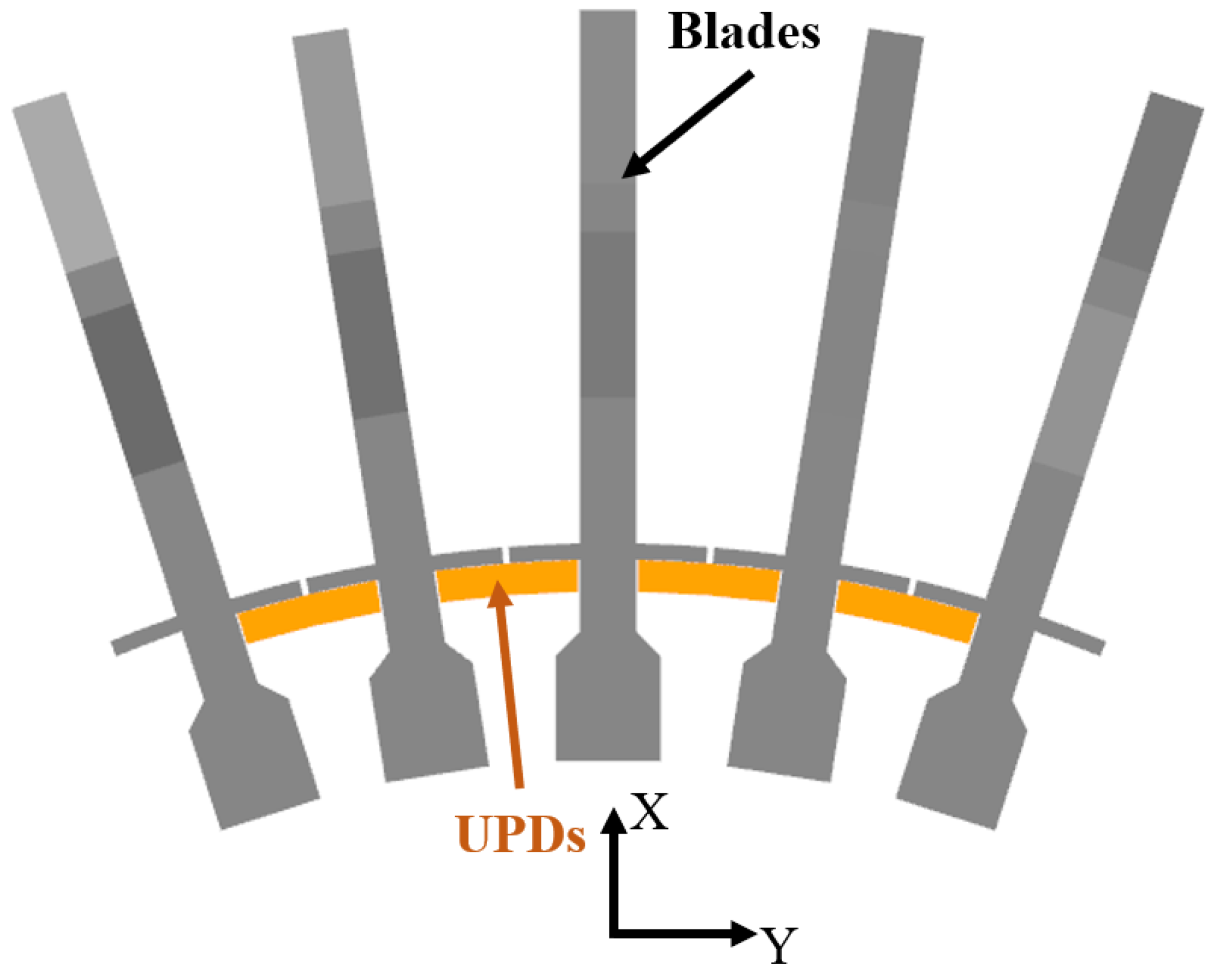
Figure 1. Model of the multi-blade system with dampers.
Aerospace 10 00725 g001
Figure 2. Vibration mode shapes and modal deformations of the simplified single blade. (a) First-order bending mode (2302.8 Hz). (b) First-order torsional mode (5123.1 Hz).
Aerospace 10 00725 g002
Figure 3. Finite element discretization of the multi-blade system with dampers.
Aerospace 10 00725 g003
Figure 4. Steps for establishing the nonlinear motion equations considering pre-stress.
Aerospace 10 00725 g004
Figure 5. Torsional vibration mode shapes (6–10th) of the system. (a) Blades; (b) UPD views in both directions.
Aerospace 10 00725 g005
Figure 6. Vibration response amplitude of blades calculated with different harmonic truncation orders nh.
Aerospace 10 00725 g006
Figure 7. Vibration response amplitude of blades under different normal loads of UPDs.
Aerospace 10 00725 g007
Figure 8. The test equipment. (a) Diagram; (b) site photo.
Aerospace 10 00725 g008
Figure 9. Schematic diagram of the vibration signal acquisition system.
Aerospace 10 00725 g009
Figure 10. (a) Radial vibration strain distribution of blade. (b) Position of strain gauges on the blade.
Aerospace 10 00725 g010
Figure 11. Installation of the multi-blade system and UPDs.
Aerospace 10 00725 g011
Figure 12. Campbell diagram of the blade and the excitation frequency for different numbers of nozzles.
Aerospace 10 00725 g012
Figure 13. Schematic diagram of the process for vibration response measurement.
Aerospace 10 00725 g013
Figure 14. Vibration strain signal after filtering. (a) Without dampers; (b) with 0.5 m0 UPDs; (c) with 1.0 m0 UPDs; (d) with 2.0 m0 UPDs.
Aerospace 10 00725 g014aAerospace 10 00725 g014b
Figure 15. Waterfall plot of vibration strain signal. (a) Without dampers; (b) with 0.5 m0 UPDs; (c) with 1.0 m0 UPDs; (d) with 2.0 m0 UPDs.
Aerospace 10 00725 g015
Figure 16. Comparison of the frequency domain curves of the experimental and numerical results. (a) Experimental result; (b) numerical result.
Aerospace 10 00725 g016
Table 1. Comparison of the effects of varying UPD masses on blade resonance frequencies corresponding to the maximum peak.
Contrast ItemWithout DampersWith 0.5 m0
UPDs
With 1.0 m0
UPDs
With 2.0 m0
UPDs
Numerical resultFrequency /Hz5124.75304.05341.55251.5
increase ratio-3.5%4.2%2.5%
Experimental resultFrequency /Hz5164.0 5322.05296.05270.0
increase ratio-3.1%2.6%2.1%
Table 2. Comparison of the effects of varying UPD masses on maximum blade responses.
Contrast ItemWithout DampersWith 0.5 m0
UPDs
With 1.0 m0
UPDs
With 2.0 m0
UPDs
Numerical resultStrain /με158.150.981.6128.3
reduction ratio-67.8%48.3%18.9%
Experimental resultStrain /με151.047.076.6139.7
reduction ratio-68.9%49.2%7.5%
Disclaimer/Publisher’s Note: The statements, opinions and data contained in all publications are solely those of the individual author(s) and contributor(s) and not of MDPI and/or the editor(s). MDPI and/or the editor(s) disclaim responsibility for any injury to people or property resulting from any ideas, methods, instructions or products referred to in the content.