Article

Systems Integration Framework for Hybrid-Electric Commuter and Regional Aircraft

by
Vijesh Mohan
,
Andrew K. Jeyaraj
* and
Susan Liscouët-Hanke
*
Department of Mechanical, Industrial and Aerospace Engineering, Concordia University, Montréal, QC H3G 1M8, Canada
*
Authors to whom correspondence should be addressed.
Aerospace 2023, 10(6), 533; https://doi.org/10.3390/aerospace10060533
Submission received: 1 April 2023 / Revised: 19 May 2023 / Accepted: 1 June 2023 / Published: 3 June 2023
(This article belongs to the Section Aeronautics)

Abstract

:
System integration is one of the key challenges to bringing future hybrid-electric and all-electric aircraft into the market. In addition, retrofitting and redesigning existing aircraft are potential paths toward achieving hybrid and all-electric flight, which are even more challenging goals from a system integration perspective. Therefore, integration tools that bridge the gap between the aircraft and the subsystem level need to be developed for use in the conceptual design stage to address current system integration challenges, such as the use of space, the share between propulsive and secondary power, required level of electrification, safety, and thermal management. This paper presents a multidisciplinary design analysis (MDA) framework that integrates aircraft and subsystem sizing tools. In addition, this paper includes improved physics-based subsystem sizing methods that are also applicable to smaller, commuter, or regional aircraft. The capabilities of the developed framework and tools are presented for a case study covering the redesign of the DO-228 with a hybrid-electric propulsion system in combination with the electrification of its systems architecture and different subsystem technologies.

1. Introduction

The aviation industry aims to reduce its environmental footprint significantly in the next two decades [1]. These aggressive targets can only be achieved with the use of novel aircraft concepts, propulsion systems, and systems technologies to improve overall aircraft energy consumption [2]. The electrification of aircraft is one of the potential methods of reducing CO2 emissions being explored by industry. Aircraft electrification can focus on using electrical power to produce thrust or the use of electrical power for systems loads, or a combination of both. However, as efficient battery technologies continue to mature, hybrid-electric aircraft are being considered as a steppingstone on the road to the fully electric aircraft. Hybrid-electric propulsion seems to be a promising field of exploration, especially for shorter-range missions, regional, commuter, or some business aircraft operations.
Examples of fully electric aircraft concepts include the Volta Volare DaVinci and Magnus Aircraft [3], whereas the Faradair Bio [4] and the Raytheon Technologies demonstrator [5] are some examples of hybrid-electric aircraft in the commuter and regional aviation categories that are under active development. Larger aircraft concepts such as the Boeing SUGAR Volt [6], NASA STARC-ABL, and the ES Aero ECO-150 [7], featuring hybrid-electric propulsion, have also been studied. Smaller aircraft carrying 19–30 passengers (PAX) on routes of up to 500 km may potentially benefit from hybridization [8]. The DO-228, in particular, has been used for conceptual studies and as a technology testbed on hybridization for this aircraft category [8,9].
Conventional aircraft propulsion systems use internal combustion engines that require fuel which is typically carried in the aircraft wings and center body fuel tanks. In turboprop aircraft such as the DO-228, the engines burn fuel to power the turbine and propellers, generating thrust. A hybrid-electric propulsion system consists of additional batteries and electric motors which run the propellers. Typical hybrid-electric propulsion system architectures are turbo-electric, series hybrid, and parallel hybrid systems.
In addition to propulsion systems, aircraft systems (sometimes called onboard systems) consist of many subsystems, such as flight control, environmental control, or electrical power systems, to name a few, which are responsible for fulfilling the functions of the aircraft and enabling its safe operation. Hybrid-electric aircraft need fuel and battery systems to fulfill the propulsive energy requirements. However, the hybridization and distribution of the propulsion systems will lead to changes and potentially higher degrees of integration with the aircraft systems (such as the flight control system or the electrical power systems) and could require the electrification of the subsystems as well. This subsystem electrification can lead to additional weight and drag penalties, and several integration challenges concerning thermal management, safety, certification, or maintainability.
The retrofitting and redesigning of existing aircraft are potential paths toward achieving hybrid and all-electric flight, which are even more challenging objectives from a system integration perspective. To determine the energy needs and weight variations at the aircraft level, conceptual designers need to study the aircraft electrification strategy hand in hand with the propulsion systems at the system and subsystem levels to determine the overall feasibility of a hybrid-electric aircraft concept. Additionally, the proprietors of smaller and commuter aircraft need to consider the potential impact of changing the certification category (i.e., from Part 23 to Part 25) due to a weight increase caused by the weight of the additional batteries. Thus, it is necessary to develop an integrated environment in which to study the coupling effect of aircraft subsystems on the aircraft level.
In this context, this paper presents a multidisciplinary design analysis (MDA) framework that allows for the analysis of the systems integration aspects of a hybrid-electric commuter aircraft, focusing on the concurrent electrification of propulsion systems and aircraft systems. This framework is part of the work of Concordia University’s Aircraft Systems Lab in conjunction with the collaborative AGILE4.0 project. The aim is twofold: firstly, to develop a sandbox environment that allows for the development and integration of new subsystem tools, such as the Aircraft System Safety Assessment Tool (ASSESS) [10] or the thermal risk assessment [11]; and secondly, to develop an MDA framework focused on aircraft and subsystem integration for smaller and commuter aircraft.
This paper begins with a literature review of the system integration methods in conceptual design and the relevant aspects of hybrid-electric aircraft sizing. Next, the proposed MDA framework for systems integration is presented and focuses on the systems sizing and weight estimation methods for regional, business, and commuter aircraft. A case study for the systems electrification and battery integration for a DO-228 aircraft, focusing on the impact of systems on aircraft weight, is then used to demonstrate the MDA framework. The paper closes with a conclusion and discussion of future work.

2. Literature Review

During early aircraft design stages, systems considerations are typically limited to weight estimation using empirical methods, such as Roskam [12], Torenbeek [13], Raymer [14], or the NASA Flight Optimization System (FLOPS) [15]. These empirical methods are valid for conventional aircraft and subsystems, except for the NASA FLOPS method, which also covers some unconventional aircraft configurations. However, such methods are not suitable for studies featuring aircraft retrofitting, the integration of novel propulsion systems, subsystems architectures, or new systems technologies. This is because most of the correlations are built on the aircraft’s maximum takeoff weight (MTOW) or the operational weight empty (OWE) and the overall granularity of these methods is insufficient.
Physics-based methods have been developed to address the shortcomings of the empirical approaches presented earlier. Physics-based modeling methods primarily focus on replacing unrelated aircraft-level parameters with system-sizing-related parameters and require a higher degree of granularity in the subsystem sizing methods, sometimes up to the component level. Among the physics-based methods, Koeppen et al. [16] established weight-based integration of system-level and aircraft-level parameters. Liscouët-Hanke [17] introduces a power-based decomposition method of the system-level parameters, allowing aircraft-level trade studies of more electric aircraft (MEA) system architectures. Lammering [18] and Chakraborty [19] have published similar methods that extend power and function-based system decomposition, providing some detailed subsystem models.
The above methods require integration with aircraft-level tools to properly assess a system’s impact on the overall aircraft weight and fuel consumption. Lammering integrates a power-based decomposition into the Multidisciplinary Integrated Conceptual Aircraft Design Optimization (MICADO) framework, enabling an aircraft resizing capability. Chiesa et al. [20] present a methodology to integrate onboard aircraft systems sizing into the aircraft-level design loop using the ASTRID (Aircraft on-board Systems Sizing and TRade-Off Analysis in Initial Design phase) tool. ASTRID integrates multiple disciplines, such as structures, propulsion, and reliability, with system sizing [21]. Another example is the research of Jünemann et al. [22] on the evaluation of more electric system architectures integrating systems sizing and architecting within the advanced aircraft configuration (AVACON) framework.
Most of the above-mentioned physics-based methods have either been validated or focus on commercial aircraft of a larger size than the current concepts for hybrid-electric aircraft. However, Fioriti et al. [23] analyze the electrification of aircraft systems within a multidisciplinary design and optimization (MDAO) framework for small transport aircraft.
In addition to weight estimation, the three-dimensional layout and estimating the space occupied by the aircraft system plays a crucial role in conceptual design [24]. The estimation of available space for systems installation within the aircraft is particularly important for hybrid-electric aircraft configurations in which significant space might be required to install batteries. However, the three-dimensional modeling is not detailed within the scope of this paper.
Hybrid-electric propulsion system sizing and integration is highly challenging, as discussed in Brelje and Martins [25]. The size of the energy storage is driven by the overall hybrid-electric propulsion system architecture and the functions fulfilled by each component. The battery and fuel weight depend on the flight phases and the aircraft mission. In addition, the system-level characteristics become even more important as the propulsion system and the subsystems become more integrated with respect to power generation, distribution, use of space, thermal management, and impact on drag. Hence, these aspects need to be investigated in an integrated environment.
Hoogreef et al. [26] propose a methodology to size regional hybrid-electric aircraft by integrating an aerodynamics module and weight methods. However, the system weight estimation is not based on the technology and subsystem parameters. Zamboni et al. [27] adopt the power path method for a coupled constraint and point mass analysis; their component sizing modules allow the overall mass of subsystems to be limited to fuel, energy storage, and geometric parameters. Kohler et al. [28] present a conceptual design of hybrid-electric propulsion systems for smaller aircraft with multiple-propulsion architecture. Another example is the study presented by Finger et al. [29], who propose a methodology to size general aviation hybrid-electric aircraft using the example of a DO-228 aircraft. This approach focuses on the hybridization factor (HP), which captures the power split between the conventional power plant and the electric motor and implements an energy-based mission analysis to determine overall fuel and battery mass. Hoffman et al. [9] analyze the impact of hybridization on the DO-228 aircraft and determine that a parallel hybrid architecture with a reduced number of passengers provides improved takeoff performance and a lower noise footprint. DeVries et al. [30] propose a hybrid-electric and distributed propulsion aircraft sizing methodology for regional transport aircraft.
Zumegen et al. [31] investigate the impact of powertrain architecture, aerodynamic interactions, systems technologies, and operating strategies on a commuter aircraft. They quantify the effect of systems technologies such as electric taxiing and electro-hydrostatic primary flight control actuation, among others, on CO2, NOx, energy costs, and noise using available literature and simplified calculations. Nasoulis et al.’s [32] multidisciplinary computational framework for hybrid-electric commuter aircraft focuses on conceptual aircraft sizing, structural analysis and optimization, stability analysis, and component placement, particularly for fuel tanks and batteries in an integrated 3D modeling environment. Gkoutzamanis et al. [33] investigate thermal management for hybrid-electric commuter aircraft, wherein they present a methodology for modeling thermal systems (TMS), including weight estimation methods. Cinar et al. [34,35] introduce a multidisciplinary aircraft sizing and synthesis framework called Electrified Propulsion Architecture Sizing and Synthesis (E-PASS), which is applied for the design space exploration of hybrid-electric commuter aircraft carrying 19–50 passengers [36]. Cai et al. [37] further investigate additional parallel-hybrid architectures using the same framework. Both studies use NASA FLOPS to make component-based weight estimates, including those of the subsystems.
The literature shows that commuter and regional aircraft are candidates for integrating hybrid-electric propulsion system architecture. The system integration challenges have not been widely investigated, particularly using conceptual MDAO frameworks. Furthermore, the state-of-the-art conceptual sizing methods for subsystems do not perform well when applied to commuter and regional aircraft categories. Therefore, there is a need for a framework that performs integrated system sizing, tailored specifically to smaller aircraft, in a way that covers the range of 10 to below 100 passengers, as well as Part 23 and Part 25 certification categories.

3. MDA Framework for Aircraft System Integration Studies

This section presents the MDA framework developed in the Aircraft Systems Lab at Concordia University to perform system integration studies in aircraft conceptual design.

3.1. Framework Overview

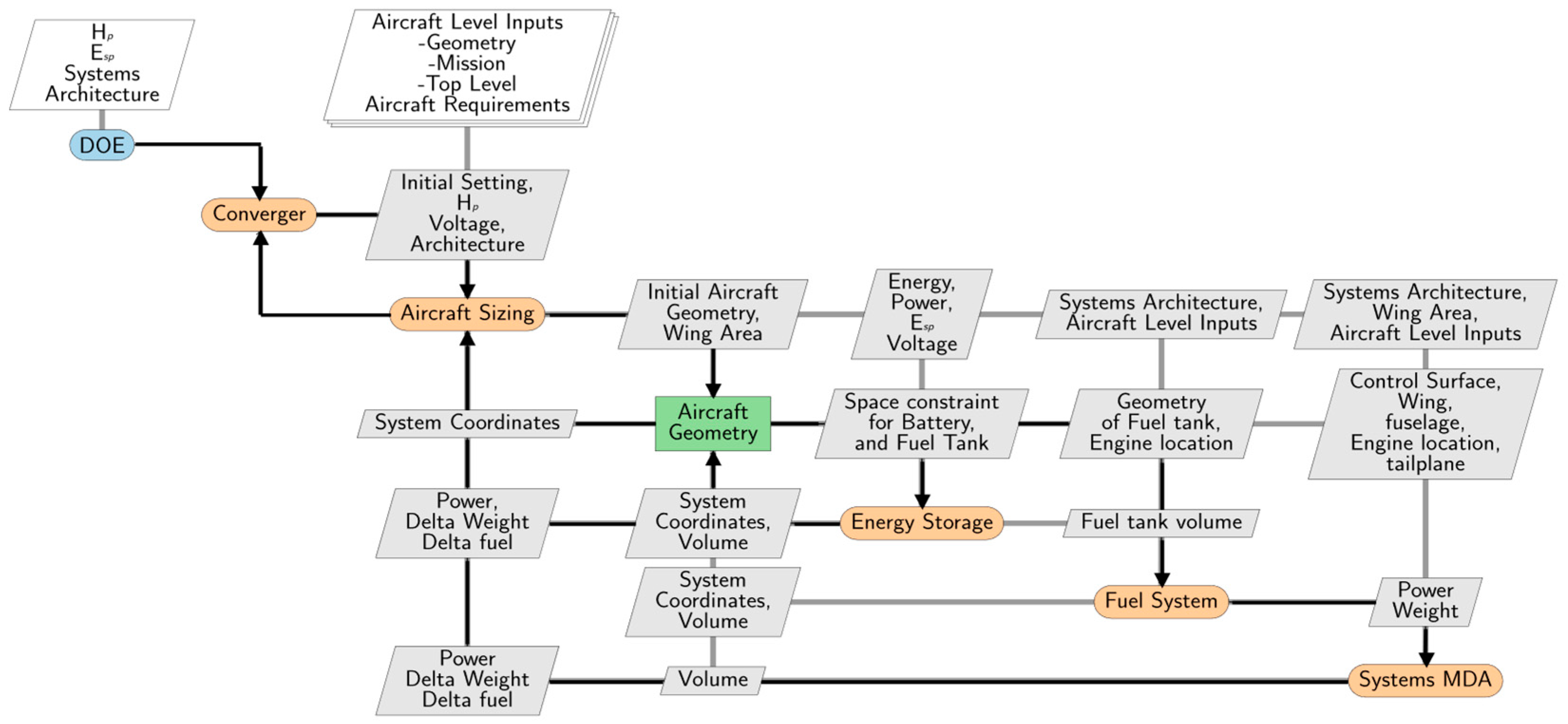
Multidisciplinary aircraft analysis consists of aircraft sizing interactions with multiple disciplines. Figure 1 shows the eXtended Design Structure Matrix (XDSM) [38] of the workflow introduced in this paper.
Here, the propulsion system architecture is handled within the Aircraft Sizing module, while the subsystem sizing methods are integrated within the Systems MDA module.
The Systems MDA discipline encompasses the aircraft systems and subsystems sizing and performance estimation modules. The Systems MDA allows for the evaluation of the impact of aircraft system architectures on aircraft-level parameters such as MTOW and fuel burn. Finally, the Systems MDA module drives system architecting and decision-making activities.
A key enabler for the Systems MDA module is the system architecture descriptor. The descriptor holds information about the architecture, including subsystems, components, and the allocation of power and control to each system architecture element. Some examples of descriptors include textual descriptors [39,40], parametric data schema such as CPACS (Common Parametric Aircraft Configuration Schema) [41], and the graph-based descriptor used by Jeyaraj et al. [10].
The Systems MDA module in the presented framework employs a modified CPACS-based descriptor. It stores aircraft-level parameters in a standard CPACS file, but captures system-level parameters and the systems architecture using custom tags defined within the tool-specific tag of CPACS.
The architecture descriptor in the Systems MDA can store information at multiple levels of granularity. For example, the allocation of control functions (e.g., roll) to control surfaces (e.g., aileron and spoiler) in the case of the aircraft flight control systems constitutes the high-level information that can be stored. More detailed architecture description, such as the instantiation of hydraulic and electrical power systems, encapsulates additional information, such as the allocated hydraulic pumps, electrical generators, tubing variants, and power converters. Furthermore, electrical, and hydraulic power systems can be allocated to specific consumers at the system and component levels. For example, an electrical system (further assigned to a particular power source such as an engine) can be configured to supply individual flight control actuators, environmental control system packs, and other subsystems such as landing gear braking. Electrical distribution voltage levels and power converters associated with each electrical system can also be specified using the descriptor.
Finally, the Systems MDA descriptor is compatible with the graph-based architecture descriptor of Jeyaraj et al. (developed to allow further safety analyses), such that the information stored in the graph-based descriptor can be written directly into the Systems MDA descriptor file. Further examples and illustrations of the Systems MDA descriptor are shown in Figure A1, Figure A2, Figure A3 and Figure A4 in Appendix A.
As the framework focuses on smaller hybrid-electric aircraft, the overall workflow also integrates modules such as Aircraft Sizing, a geometric modeler (Aircraft Geometry), Energy Storage, Fuel System, and Systems MDA. Among these subsystems, Fuel System undergoes significant variations due to hybridization. The level of hybridization will lead to the aircraft fuel system needing less space or potentially accommodating different fuel types. Moreover, the propulsion system of the aircraft will need additional energy storage to fulfill the energy needs in the form of batteries. Therefore, separate tools have been developed for both types of systems [42,43]. In the workflow, it is proposed to include them independently as they drive the geometrical layout. Moreover, this implementation will enable future expansion to other technologies, such as hydrogen storage.
The framework is implemented using Python and RCE [44], which enables integration between the different tools. The interface between the tools uses the CPACS standard, which allows for easy integration with other tools in collaborative workflows, such as those in the AGILE 4.0 project.
The systems integration process begins with the initial convergence of the aircraft design loop. Initial estimates on parameters, such as geometry and energy storage sizing, are available as outputs. The initial aircraft geometry parameters are provided as input to the aircraft design module as the current workflow focuses on redesigning an existing commuter aircraft.
The Aircraft Sizing tool developed by Licheva and Liscouët-Hanke [45] is used to size the hybrid-electric aircraft used in this case study. The tool covers conventional, hybrid-electric, and all-electric propulsion configurations. The conventional aircraft sizing process estimates the initial mass of the aircraft, followed by an estimation of the power plant and wing characteristics according to individual flight phases. An overall mission-level analysis is carried out to converge the aircraft’s maximum takeoff weight (MTOW). The Aircraft Sizing tool uses the top-level aircraft sizing parameters and design of experiment (DOE) parameters such as hybridization of power (Hp) and specific battery energy density (ESP) to generate initial estimates of aircraft geometry and battery weight, thereby converging the MTOW and the required wing area. Powertrain electronics are not modeled, and a simplified propulsion system model based on individual component efficiencies is employed. Additional outputs, such as space constraints and assignments for batteries and fuel tanks, are available after the analysis. An initial estimate of the system’s weight and required power is also available as an output of the Aircraft Sizing tool. The drag penalty stemming from the systems will be integrated into a future version of the tool.
The Energy Storage tool developed by Heit and Liscouët-Hanke [43] is used to size the battery used in the case study. This tool uses overall energy and power requirements from the initial Aircraft Sizing to estimate the size of the battery required to fulfill the aircraft requirement. The tool estimates the required space based on the aircraft design output parameters and the initial space assignment by the geometric modeler. The battery tool considers the conventional cuboidal packing method of cells with dimensional constraints.
Since the current workflow only supports cuboid battery shapes, we assume that the battery is placed in the center wing box for simplicity. Battery placement in wing tip locations might be interesting from a wing-loading perspective, but making assessments of this requires more capable battery layout tools to capture the physical limitations of such configurations realistically.
The output of the Energy Storage module is fed to the Fuel System sizing module developed by Rodriguez and Liscouët-Hanke [42]. The Fuel System considered within the workflow consists of all the subsystems that store and transfer the fuel required for a conventional propulsion system. The updated outputs from the aircraft geometric modeler are available as inputs to the Fuel System. These inputs, along with top-level aircraft parameters and system architecture, are used to estimate engine feed subsystems, fuel quantity indicators, and venting subsystems. The overall integration at the system level allows us to estimate the total power and weight outputs. The finalized Fuel System weight and the aircraft geometric outputs are inputs to the Systems MDA module. Moreover, the Fuel System weight and power required are merged with the outputs of the Systems MDA module.
The final weight outputs from the Energy Storage and Systems MDA module are used to estimate overall weight change Δ O W E S I and Δ W F S I . In the Converger module, the variations from the subsystems are fed back into the Aircraft Sizing module to update aircraft design parameters, O W E and W F , and these updated parameters can be used to resize the aircraft. However, in the presented case study, the Converger module only updates the wing area to compensate for the increased MTOW. This study uses a simplified resizing of the aircraft, focusing only on calculating the wing area required to carry additional weight due to the systems in order to demonstrate the capabilities of the integration framework. Additionally, the DOE module is used for parametric analysis, as presented in the case study (Section 4).

3.2. Systems MDA: Aircraft Systems Sizing Estimation Tool (ASSET) for Commuter and Regional Aircraft

Aircraft systems sizing within the framework is structured in three types of subsystem categories, as proposed by [17]. These are power-consuming systems, power transformation and distribution systems, and power generation systems. This categorization based on the functions and power flow patterns eases the sizing relationship between the subsystems. Table 1 presents the considered subsystems and an overview of the associated modeling assumptions.
The framework is built to easily adapt and include additional subsystems (e.g., a pneumatic or fuel cell power system). However, this paper’s scope is restricted to demonstrating the integration and trade study capability of a subset of these subsystems: the flight control system, the hydraulic power system, and the electrical power systems.
The framework implements a fully nested systems analysis in order to size the systems at each level, as depicted in Figure 2. The aircraft level parameters, geometric parameters, and system architecture inputs are used to initialize the sizing process. The outputs of the power-consuming system module are used to size the Power Transformation and Distribution System. The Power Generation System and Energy Storage module sizes the stored energy necessary to operate secondary power systems (e.g., the emergency battery in the electrical power system or the battery for starting the APU) and should not be confused with the propulsive power energy storage sizing (propulsion battery in this case). The Systems MDA module can size the electrical power generation based on the total required power from various subsystems, including energy storage and novel power generation systems.
The following subsections explain a chosen set of subsystems and their sizing principles in more detail. We only describe the submodules that are examined in more detail in the case study.

3.2.1. Flight Control System

The flight control system (FCS) considered within the framework corresponds to all systems and subsystems responsible for the actuation of the control surface except for the flight control computer (FCC), which is responsible for signaling the actuators and is considered within avionics systems. The overview of this module is depicted in Figure 3.
The inputs to the module are system architecture, aircraft-level parameters, and wing characteristics defined by the aircraft design. The aircraft-level parameters are the control surface descriptions and their corresponding locations. The systems architecture corresponds to the subsystem architecture as included in the architecture descriptor. The wing area characteristics correspond to the updated wing area parameter within the output of aircraft design.
The control surface parameters are used to estimate the hinge moment of the control surface. The framework evaluates the hinge moment by using two methods depending on the wing definition. The DATCOM (data compendium) method [46] is used when the wing has a symmetrical airfoil. The method developed by Anderson et al. [47] is used for non-symmetric or supercritical airfoils. The comparatively simpler Anderson method can easily be adapted with additional factors for application to unconventional airfoils. However, the hinge moment is an important interface parameter between the control surface and actuation sizing and requires that additional physics-based research be conducted to improve accuracy.
The FCS module is capable of analyzing several actuation technologies, such as mechanical actuation, hydro-mechanical actuation (HMA), electro-hydraulic servo-actuation (EHSA), more electric actuators, such as electro-hydrostatic actuators (EHA), and all-electric type actuation, like electro-mechanical actuators (EMA). Mechanical linkages are supported as smaller aircraft typically use this form of flight control actuation. The power drive unit (PDU) is considered for the flaps and slats. Hydraulic system pressure is used as a global parameter for hydraulic actuation. Electric actuation can be modeled with discrete AC or DC voltage levels such as 28, 115, 230, and 270 V. The limitation occurs due to the limited data availability for power transformation and distribution systems.
The power demand of the flight control system is estimated bottom-up from the individual actuators. To do so, the tool estimates the maximum power demand P m a x   ( W ) from the hinge moment H M c s   ( N / m ) and the deflection rate of the control surface δ ˙ ( r a d / s ) using Equation (1).
P m a x = H M c s · δ ˙ · f c , A C T
Typically, only the maximum values H M c s and δ ˙ are available in a conceptual design. Therefore, Equation (1) includes a correction factor f c , A C T . In a conservative approach, the correction factor can be 1; however, if the conceptual designer has some experience, different factors can be applied to different actuators to reflect the variations better.
For simplicity, it is assumed that each actuator on the control surface can support the maximum load of the control surface. The power demand of the actuator per flight phase is then estimated as a ratio adapted based on the maximum power for each flight phase. Typical values for the case study are presented in Table A3 in Appendix B.
Even with a more electric and hybrid-electric architecture, smaller aircraft can potentially still completely contain mechanical surface actuation (due to low hinge moments for low-speed operation or small control surfaces). Therefore, the presented framework includes the weight estimation of a mechanical push–pull rod actuation. This is adapted from the method presented by Torenbeek [13], which uses the MTOW as the main parameter in the empirical weight estimation. Here, the authors modified it to use the control surface area S c s in ( m 2 ) as input. The resulting equations for the various control surfaces are presented in Table 2.
As an additional feature, mechanical backup linkages can also be assigned to the hydraulic actuation with mechanical signaling based on information presented in SAE ARP5770 [48]. Based on this standard, the primary flight control mechanical linkage cannot be less than 1/8 in; this allows for a reduction in linkage weight of about 12% when the application is limited to signaling. This is further applied to the Torenbeek estimation method if the mechanical linkage is assigned for signaling.
The weight estimation of conventional HMA and EHSA actuators is implemented using power-to-weight ratios (P/W) drawn from the literature, which are provided in Table A4 of Appendix B. The EHA and EMA actuators require additional power electronics components; their weight is accounted for using their specific P/W
As the power demand of the actuators is not constant throughout the flight, the power demand per flight phase is calculated using a factor that is multiplied by the maximum power demand calculated in Equation (1).
Hydraulic and electrical actuation is modeled based on an object-oriented approach where each subsystem corresponds to an object. Each object is identified as an electric or hydraulic subsystem based on system-level architecture inputs. This can also be assigned to a specific power transformation and distribution system. The methodology of systems allocation is similar to the methods presented in [18]. The following sub-section will explain the subsequent sizing of the hydraulic and electric power systems.

3.2.2. Hydraulic Power System

The hydraulic system within the framework considers all the systems and subsystems responsible for generating and distributing hydraulic power within the aircraft, unless there is a localized standalone hydraulic system (as is the case with EHA implementations). The method follows the logic tree presented by Liscouët-Hanke [17]. The framework considers distribution, conversion, and generation subsystems. The distribution consists of hydraulic fluid, tubing, and reservoir assembly. All the power-consuming systems which request hydraulic flow demand are assigned to a specific distribution system. The specific distribution system is then assigned to a specific generation system. This implementation will ease the future integration of automated safety assessment, as presented in Jeyaraj and Liscouët-Hanke [10].
For hydraulic actuators, the power per actuator calculated in Equation (1) is translated into a hydraulic flow requirement using Equation (2)
Q ˙ A c t = P A c t p s y s . η A c t
where Q ˙ A c t is the flow demand, η A c t is the efficiency of the actuator, and p s y s is the pressure rating of hydraulic system (typically 3000 or 5000 psi or the associated values in SI units).
The net flow demand for a hydraulic system corresponds to the total flow demand made by the connected subsystems within power-consuming systems:
Q ˙ H y d , s y s , i f l i g h t p h a s e = Q ˙ P C S , i f l i g h t p h a s e
where Q ˙ H y d , s y s , i is the hydraulic system flow demand associated with a particular central hydraulic system i, and Q ˙ P C S , i is the flow demand of the consuming systems connected to this hydraulic system i. The system architecture descriptor performs the association between consumer systems (on the actuator level) with the different hydraulic systems. The number of hydraulic systems varies depending on the overall system architecture (typically between 0 and 3).
As a next step, the hydraulic pumps associated with the hydraulic systems are sized accordingly. The model contains the following pump types: engine-driven pumps (EDP), electric motor pumps (EMP), (rarely used) air turbine-driven pumps (ATDP), power transfer units (PTU), and emergency pumps associated with the ram air turbine (RAT).
The Q ˙ H y d , s y s , i of the individual hydraulic system is supplied by the associated hydraulic pumps, typically one EDP and one EMP, in conventional aircraft. For more than one EDP, Q ˙ E D P = Q ˙ H y d , s y s , i / N E D P , where N E D P is the number of EDP available within the hydraulic system.
If the EMP if set as a backup, it only compensates the flow when the engines are at idle, according to the SAE ARP6277 [49]; this corresponds to Q ˙ E M P = 0.16 Q ˙ H y d , s y s , i . However, if the EMP is not a backup, then Q ˙ E M P is equal to Q ˙ H y d , s y s , i . It should be noted that the Q ˙ E M P power can be set based on the architecture of the hydraulic system.
One of the major assumptions considered within hydraulic system sizing is the type and number of pumps associated with each hydraulic system and the power split between these pumps. This implementation enables system safety assessment integration within the system architecting process. However, this paper focuses on a simple example to illustrate the sizing capability for a set of given architectures.
For example, for sizing the EDPs, Equation (4) can be used, where Q ˙ E f f is the adjusted available flowrate considering the engine operation with respect to the flight phase and n E N G , s h a f t , % is the associated shaft speed percentage of the engine, and the EDP efficiency η E D P :
Q ˙ E f f E D P ( f l i g h t p h a s e ) = Q ˙ E D P ( f l i g h t p h a s e ) n E N G , s h a f t , % ( f l i g h t p h a s e ) . η E D P
Once the EDP is sized, the engine shaft power off-take can be estimated.
For EMPs, the required flow demand must be translated into electrical power demand, which impacts the sizing of the electrical power systems, discussed in the following subsection. All efficiency and power-to-weight ratio assumptions for the weight estimation of the pumps are provided in Table A4 of Appendix B.
The net shaft power requirement due to the EDP can be calculated as follows:
P s h a f t , h y d = Q ˙ E f f E D P , i . p s y s η g b
where P s h a f t is the engine shaft power requirement and η g b is the gear box efficiency. For simplicity, sizing assumes p s y s to be the maximum pressure rating of the system.

3.2.3. Electrical Power System

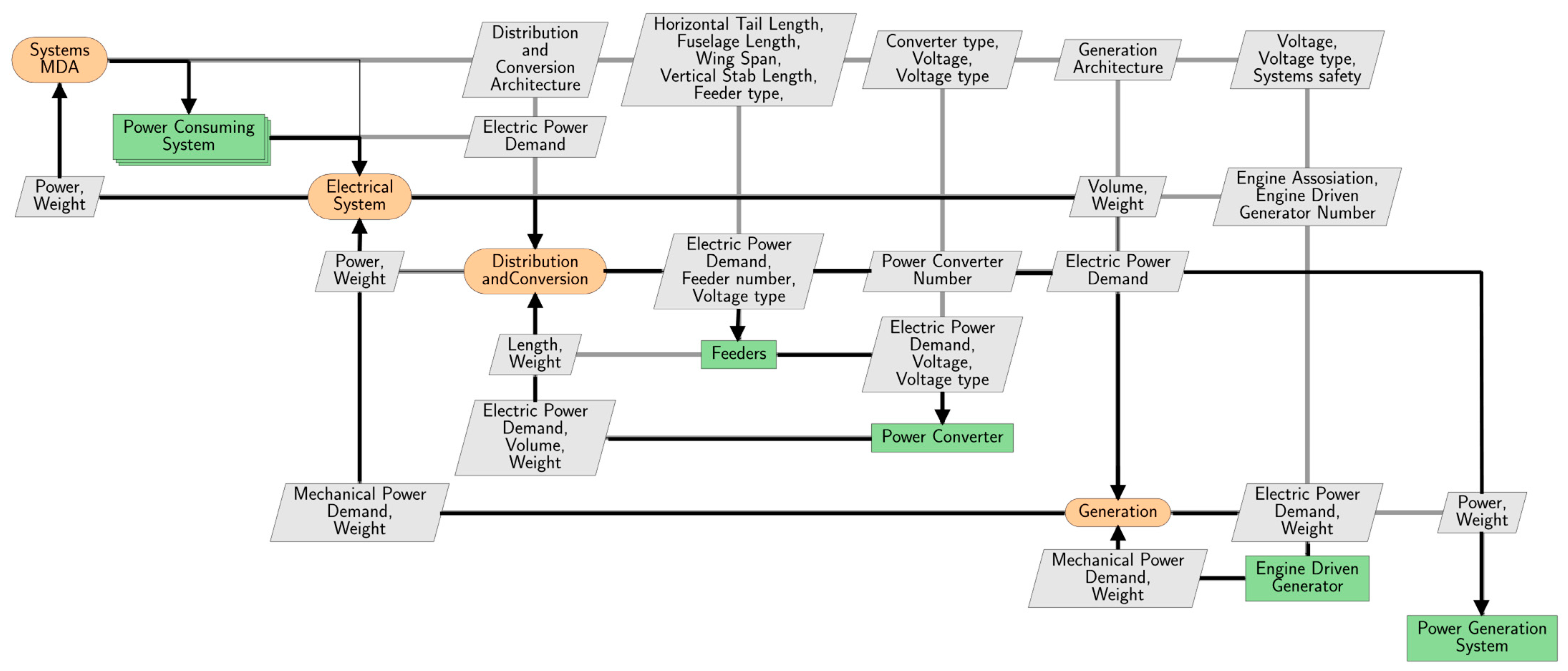
The electrical system within the framework corresponds to all the systems and subsystems responsible for generating, converting, and distributing electrical power supply, as shown in Figure 4.
The overall structure of the electrical system sizing methodology is based on the approach developed by Liscouët-Hanke. However, more detail is added to the distribution and conversion system, which consists of feeders and power converters. Alternating current (AC) feeders and direct current (DC) feeders are modeled with multiple voltage assignments in order to estimate the entire load on the feeder based on consumer assignments.
Researchers have developed a more detailed wiring weight estimation method as determining wiring weight is essential, particularly for more electric aircraft. The method is based on using the SAE AIR6540 [50] to estimate the feeder weight, giving consideration to voltage variations. Parameters such as bundle loading and altitude factors are used to account for the wiring losses. Additionally, phase lagging is considered through the power factor for AC. The SAE AS50881 [51] is used to model different sizes of feeders. Aircraft level parameters are used to add feeder length. This is performed based on the location of the electrical power consumer. Furthermore, this approach considers the wires to have a modified PFA (Perfluoroalkoxy) insulation which is rated up to 1000 volts.
The workflow accounts for the feeders of power-consuming and generation systems. These feeders are responsible for providing power from the power generation system (such as engines or APUs) to the power transformation and distribution system (i.e., electric generators or EMPs). The basic consideration given for the length estimation is the actual location of the generator within the engine from which the wiring starts.
L W i r e , e n g = z g e n + x g e n
where L W i r e , e n g is the wiring length from the engine to the engine attachment with the wing or fuselage; z g e n and x g e n are the coordinates of the generator. If the location of the generator is unknown, L W i r e , e n g can be assumed to be the sum of half the diameter and half the length of the engine. This is applicable to any type of engine attachment, including blended wing body aircraft configurations with embedded engines.
To represent the wiring length from the generation to the distribution conversion L w i r e , g e n e l e c , the subsystem location factor f l o c a t i o n is introduced, which is the ratio of the distance between generation and conversion to the fuselage length. The wiring length can be calculated according to Equation (7) as a function of the fuselage length L f u s e l a g e :
L w i r e , g e n e l e c , f u s e l a g e = f l o c a t i o n · L f u s e l a g e
For subsystems such as APU, which is traditionally placed at the aft fuselage, f l o c a t i o n = 0 .9 can be used. For fuselage, mounted engine f l o c a t i o n = 0.8 can be used for simplicity. If the battery is placed near the power conversion system, a value of f l o c a t i o n = 0 is used to eliminate the length. The maximum value of f l o c a t i o n = 1 is applicable to a tail-mounted engine configuration with an electrical subsystem placed in the front fuselage. For a wing-mounted engine configuration, a value of f l o c a t i o n = 0.5 can be used for simplicity. Additionally, the subsystems placed within the wing need to consider the length of wiring in the wing.
For low-wing configurations, the length of wiring is:
L w i r e , e n g e l e c , w i n g = y e n g cos Λ
where y e n g is the distance of the engine from the aircraft center axis along the y axis, and Λ is the wing sweep angle,
For high-wing configurations, one needs to account for additional wiring in the fuselage, considering the fuselage diameter D f u s e l a g e :
L W i r e n g e l e c = y e n g cos Λ + D f u s e l a g e
For the consumer wiring, it is assumed that the feeders power several subsystems along the fuselage, leading to the accumulation of the power demand, which is fulfilled by the power conversion system. Hence, except for the flight control system, the wiring is assumed to run across the fuselage. The critical parameters for the flight control system are the electric subsystem in the wings and tail section, which triggers the wiring length extension to the subsystem location. Equation (7) can be adapted to estimate the length of consumer wiring. However, the parameter f l o c a t i o n will need to consider the maximum distance between connected subsystems. For the consumer system within the wing, Equations (8) and (9) can be adapted to replace y e n g with m a x ( y c o n s u m e r i ) connected to the feeder within the wing.
The aircraft can use AC and DC types of generation systems. The DC system consists of a two-wire setup, and the three-phase AC uses a three-wire setup. The DC system benefits from using the airframe as a ground return carried by one of the wires. This kind of architecture is modeled by halving the length of the wires. The high voltage return line considerations must meet the certification requirements due to electromagnetic interference and safety hazards. Additionally, composite structures pose a high resistance to the return line, requiring detailed study to enable ground return capability. These cases must consider a dedicated return line for the aircraft systems wiring.
L W i r i n g , D C g r o u n d   r e t u r n = 1 2 L W i r i n g , D C
where L W i r i n g g r o u n d   r e t u r n is the wiring length when the ground return is possible, typically in a ‘DC’ system measured in m .
The net electric power demand on the distribution system is estimated by considering the voltage drop across the length of the wiring.
V W i r e , e f f = V W i r e + V d r o p
I e f f = I f B u n d l e   L F × f A l t i t u d e   D F
where V W i r e f f is the effective voltage estimated in V , V d r o p is the voltage drop across the wiring length in V , f B u n d l e   L F is the bundle loading factor, and f A l t i t u d e   D F is the altitude derating factor. The f B u n d l e   L F ,   f A l t i t u d e   D F and V d r o p as functions of wire resistance across the length are estimated based on [50]. A wire resistance correction factor is applied for AC feeders to account for skin effects due to high frequency. The SAE method for AC wires is valid until 1 kHz. Additionally, frequency is also used to estimate AC inductance, which is then used to update the voltage drop. The current case study assumes a 400 Hz frequency for AC wiring. For simplicity, the bundle loading is considered to be 100%, and the single wire resistance is considered to be 62 ohms/1000 ft as per recommendations from [50]. With the known effective current I e f f , one can use the lookup table provided in SAE AS50881 [51] to shortlist the required wire size. The lookup table consists of a wire gauge (AWG) and the specific weight. The power on the feeders can be estimated as follows:
P W i r i n g = I e f f . V W i r e , e f f
The power converter options in the model consist of AC/AC, AC/DC, DC/AC, and DC/DC converter types, with voltage levels of 28, 115, 270, and 230 V. The values are limited due to the data availability of power converters for aerospace applications. The sizing of the power converters is based on overall power consumption. The power converter weight variations for electric aircraft can be found in [52,53]. The AC/AC type of power converter is one of the heaviest subsystems since it consists of several components, adding to the P/W ratio [54,55]. The DC/DC converter consists of fewer components and is lighter. The power converter improvement in power density of over 5 kW is considered using the consumer load on the power converters. The generation and distribution systems are linked with power converters within the electrical system framework. This means that all the feeders must be interfaced with power converters.
The electrical power generation system consists of AC or DC generators (according to the overall electrical system architecture) and can contain additional elements, such as a hydraulic motor generator with voltage levels similar to those of power converters. The sizing of the generation system is based on the minimal safety considerations as given in [17], considering three scenarios: normal operation, single-engine failure, and a combined failure (conditions of the single-engine being off and opposite generator being off). Additionally, safety conditions will be considered upon integration with the ASSESS tool developed by Jeyaraj et al. [13]. The sizing considers the power demand of all associated consumers (implemented in a dedicated model in the framework) per flight phase and for normal and degraded operation, selecting the maximum power as the generator sizing point. The generators’ power extraction can be translated into the mechanical power demand from the engine.
The net power demand by the electrical generators is translated into the engine’s secondary power shaft in terms of mechanical power demand.
P s h a f t , e l e c = P g e n , i η g b
where P s h a f t , e l e c is the shaft power demand of electrical generators, η g b is the secondary power gearbox efficiency, and P g e n is the power demand of the electrical generator.

3.2.4. Electrical Power Consumer Systems

The electrical power consumers consist of subsystems that depend on electrical power for their functionality. These include galley, entertainment, furnishing, lights, avionics, instruments, electrically driven hydraulic pumps, air-conditioning fans, and fuel pumps. In a more-electric aircraft, additional and significantly higher electrical loads consist of the air-conditioning system, ice protection system, and any electrical actuation (e.g., landing gear and flight controls).
Categorizing AC and DC power consumers depends on specific requests by the subsystems. Voltage and voltage type-based decomposition is also generated to assign feeders to the subsystem and the electrical generation. As discussed earlier, the voltage levels are limited by the data availability of power converters. Table A1 in Appendix B presents a summary of the electrical power consumers’ equations.
In conventional aircraft, the galley, entertainment, and furnishing are the most significant power consumers within the aircraft systems. These are operated as per the aircraft configuration and passenger demands. However, these loads can be shed during emergency conditions when considered non-essential (this might differ for business aircraft operations). The electric power demand estimation of the galley, entertainment, and furnishing subsystems in this paper is adapted from the methodology established by Esdras and Liscouët-Hanke [56]. The nominal electric power demand for these systems P G E F , n o m is defined in Equation (15) as a function of the fuselage length L f u s l e a g e , fuselage width W f u s e l a g e , and the number of engines N e n g .
P G E F , n o m = 10.284 e 0.0139 L f u s l e a g e . W f u s e l a g e N e n g
The nominal power demand, P G E F , n o m , must be multiplied by the empirical usage factors provided in Appendix B, Table A7, to obtain the power demand per flight phase.
The galley, entertainment, and furnishing contribute significantly towards the aircraft’s overall weight. The method used by Anderson et al. [47] has applications specifically to larger aircraft and overpredicts the weight of these systems for smaller commuter aircraft. This paper considers the weight build-up of the subsystems based on the number of passengers, the number of crew, and cabin volume. Smaller aircraft, such as Dash 6 or Cessna aircraft, typically have front and aft baggage compartments and different cabin layouts are enabled by trading passenger seats with baggage area. Therefore, the method presented here considers the front and aft baggage volume along with the cabin volume in order to estimate the net weight of the galley, entertainment, and furnishing subsystems. The weight of the galley, entertainment, and furnishing subsystem W G E F ( k g ) can be estimated using Equation (14), with N c r e w as the number of crew members, N p a x as the number of passengers, and V c a b i n as the cabin volume in f t 3 and the factor k G E F :
W G E F = k G E F . N c r e w + N p a x 1.65 V c a b i n 0.18
where k G E F depends on the size of the aircraft:
  • k G E F = 9.1 for commercial aircraft with N p a x 60
  • k G E F = 15.2 for business jet and commuter aircraft 10 N p a x > 60
  • k G E F = 25.3 for smaller aircraft N p a x < 10
Although the above equations can also be used to estimate W G E F for commercial aircraft, the current study focuses more on smaller aircraft; therefore, detailed validation was only performed for aircraft up to the size of an Airbus A320. It has to be noted that, depending on the equipment level for the various flight operations, larger variations can occur for galley weight. However, the presented method is suitable for comparing different power system architectures for the same baseline aircraft.
The net shaft power demand can be estimated from Equations (5) and (14) as follows:
P s h a f t , e n g = P s h a f t , h y d + P s h a f t , e l e c
where P s h a f t , e n g is the net engine shaft power.
Systems MDA estimates net mission fuel consumption due to systems as per SAE AIR1168/8 [57,58]. The total fuel consumption is due to the fixed systems weight component itself, shaft power demand, bleed air component, ram air component and variable weight penalty, which corresponds to expandable material.
W F , s y s = W F , w e i g h t + W F , b l e e d + W F , s h a f t + W F , r a m + W F , v a r w e i g h t
Scholz [59] provides a methodology with which to estimate the specific fuel consumption due to systems (SFCp). According to Scholz, a shaft power factor (kp) translates SFC into SFCp. As per the turboprop engine used on the DO-228, and data availability [59], a kp value of 0.00404 is assumed in the current workflow for the fuel weight estimation. The Federal Aviation Regulation (FAR) Part 23.831 and Part 25.831 set the bleed air requirement as 0.55 lb/min/pax. This is translated into the bleed air requirement for conventional configurations. MEA and AEA configurations without engine bleed off-takes have dedicated ram air inlets, and the bleed air requirements are translated into ram air requirements.
3.3. Validation

The tools implemented in the workflow are validated using data available in the literature from studies such as [60,61] at the aircraft, subsystem, and component levels. Publicly available validation data for system weights are sparse in this aircraft category. A more detailed validation (for the Dash 6 and the ATR42) is presented in [62]. Overall, the error range at the aircraft level (e.g., for MTOW) runs from −9% to 13%, which is an acceptable range for conceptual design methods. The overall system weight error is up to 10% and shows the expected level of sensitivity to architecture and technology options. However, combining various subsystem estimations with uncertainty and error variations calls for proper uncertainty management and analysis which will be addressed in future work.

4. Case Study for the Electrification of a Commuter Aircraft

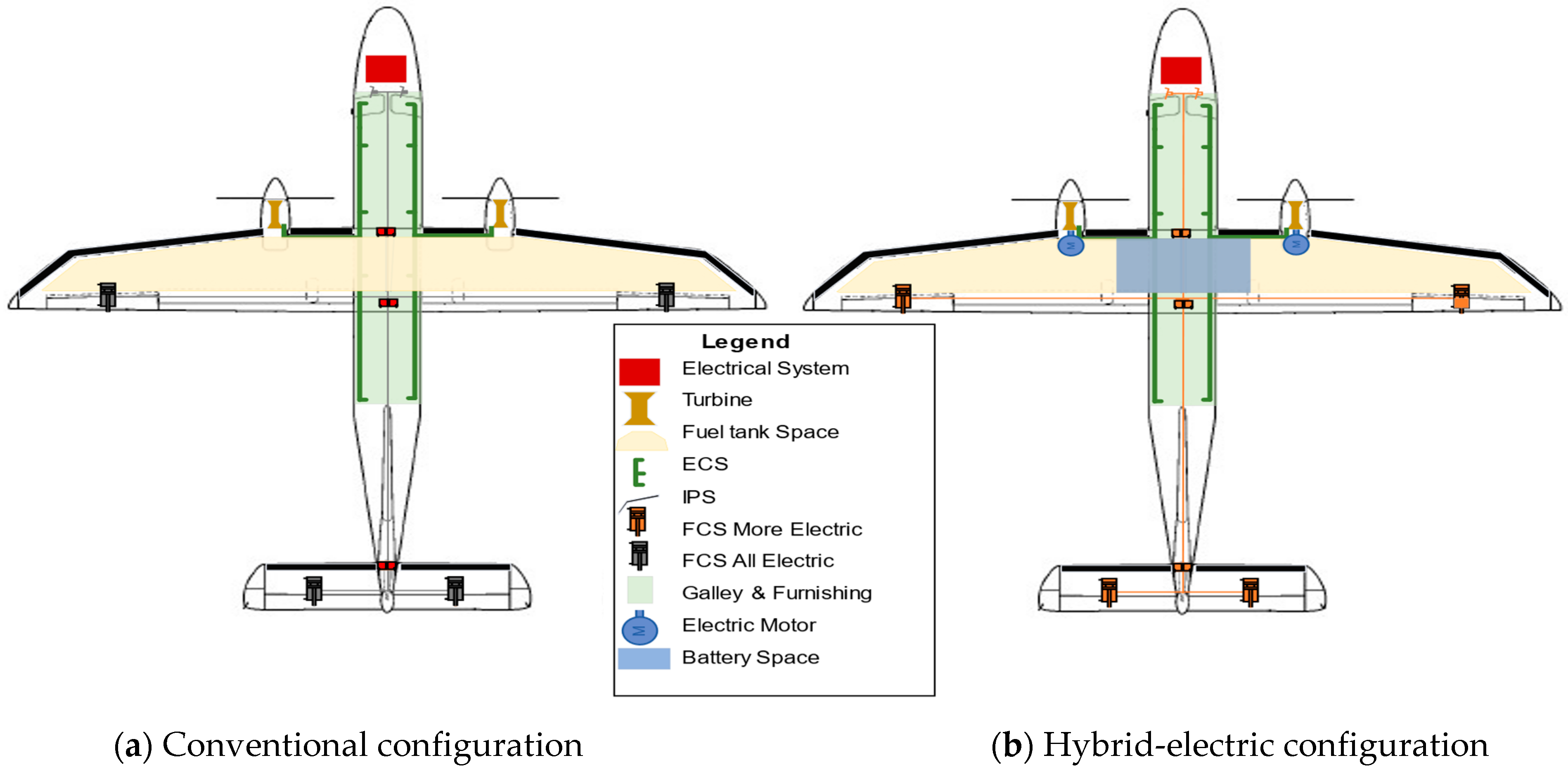
The DO-228 is selected for the case study due to the high availability of aircraft and subsystem data. The conventional DO-228 aircraft is a high-wing monoplane with two turboprop engines. This aircraft is mainly used as a commuter or utility aircraft. Figure 5a shows the conventional DO-228 configuration, whereas Figure 5b shows the hybrid-electric version considered for the case study.
The conventional version of the DO-228 is certified for Part 23 and can carry up to nineteen passengers and two to three crew members. The aircraft is designed to operate day and night during all weather conditions within temperature limits of −40 °C to +50 °C. It is equipped with de-ice boots on the wing and a pneumatic anti-ice system for leading-edge slats, propellers, and pitot tubes. Two integral fuel tanks are located on each wing between the leading edge and trailing edge spars. The Fuel System allows interconnection between the tanks via a cross-feed using jet pumps. The hydraulic system actuates the landing gear, brakes, and nose wheel steering. The hydraulic system is pressurized to 3000 psi using a DC electric motor.
The electrical system of the DO-228 is a 28 V single-wire installation, with the airframe used as a ground return. The system consists of two engine-driven generators, two batteries for the DC power supply, and two inverters for AC power consumers. All the inputs required for the analysis are summarized in Table 3 below.
The overall MDA tool validation is carried out with the conventional DO-228 architecture. The actual DO-228 MTOW from the references is approximately 6400 kg. The MDA final output is about 6372 kg. This corresponds to a −0.5% error variation.

5. Results

This subsection presents the results of the analysis with the complete workflow presented in the previous section. The aircraft-level input data required for the hybrid-electric case studies come from the literature [29,60,61,63]. The workflow considers a short-range mission, which is defined at a range of 213 NM and a payload of 1960 kg, to estimate the fuel burn for the hybrid-electric version of the aircraft. It should be noted that the range and payload remain the same for all comparisons. Additional structural reinforcement of landing gear is not considered directly to accommodate the increased aircraft MTOW.
The results for the conventional (non-hybridized) DO-228 are summarized in Table 4. The propulsion system architecture consists of a parallel-hybrid configuration with a hybridization factor of Hp = 0.1. The specific energy of the battery E s p is assumed to be 272 Wh/kg (representing current battery technology from [64]). Different system architectures are investigated, focusing on the various levels of electrification of the actuation systems and different voltage levels for the electrical system. All the key inputs and systems architecture variations are listed in Table A6 of Appendix B.
The current workflow assigns the fuel volume based on the available fuel tank volume. However, the comparison needs to be carried out with the reduced fuel tank volume of the hybrid-electric variant. The geometric modeler assigns the initial aircraft geometry to the battery sizing tool, which computes an estimate of the space consumed by the batteries. The remaining volume is assigned to the Fuel System and is also an input to the Fuel System sizing process. The finalized geometry and Fuel System weight is used within the Systems MDA framework to analyze the weight and power consumption due to all other systems. Table 4 shows the DO-228 results for a conventional and a hybrid configuration.
The final integration uses the overall delta weight estimated between the initial Aircraft Sizing and the weight values calculated by the Energy Storage, Fuel System, and the Systems MDA tools. This weight value is used to update the OWE and, thus, MTOW. Table 4 shows the final results with the updated wing area due to the aircraft’s overall weight increment. The systems and batteries remain the main contributors to the weight variation for a hybrid configuration. While the battery weight increment is due to hybridization, modifying the aircraft geometry to support new battery weight for a conventional systems configuration lead to an increment in systems weight.

Parametric Analysis

This section presents a systems-specific parametric analysis carried out on DO-228 aircraft. The conventional aircraft configuration is electrified by modifying key aircraft systems to analyze the effect at the aircraft level. The study includes multiple hybridization factors such as 0, 0.1, 0.15, and 0.2 with the current battery technology (272 Wh/kg) to obtain more realistic system-specific effects on MTOW and the wing area.
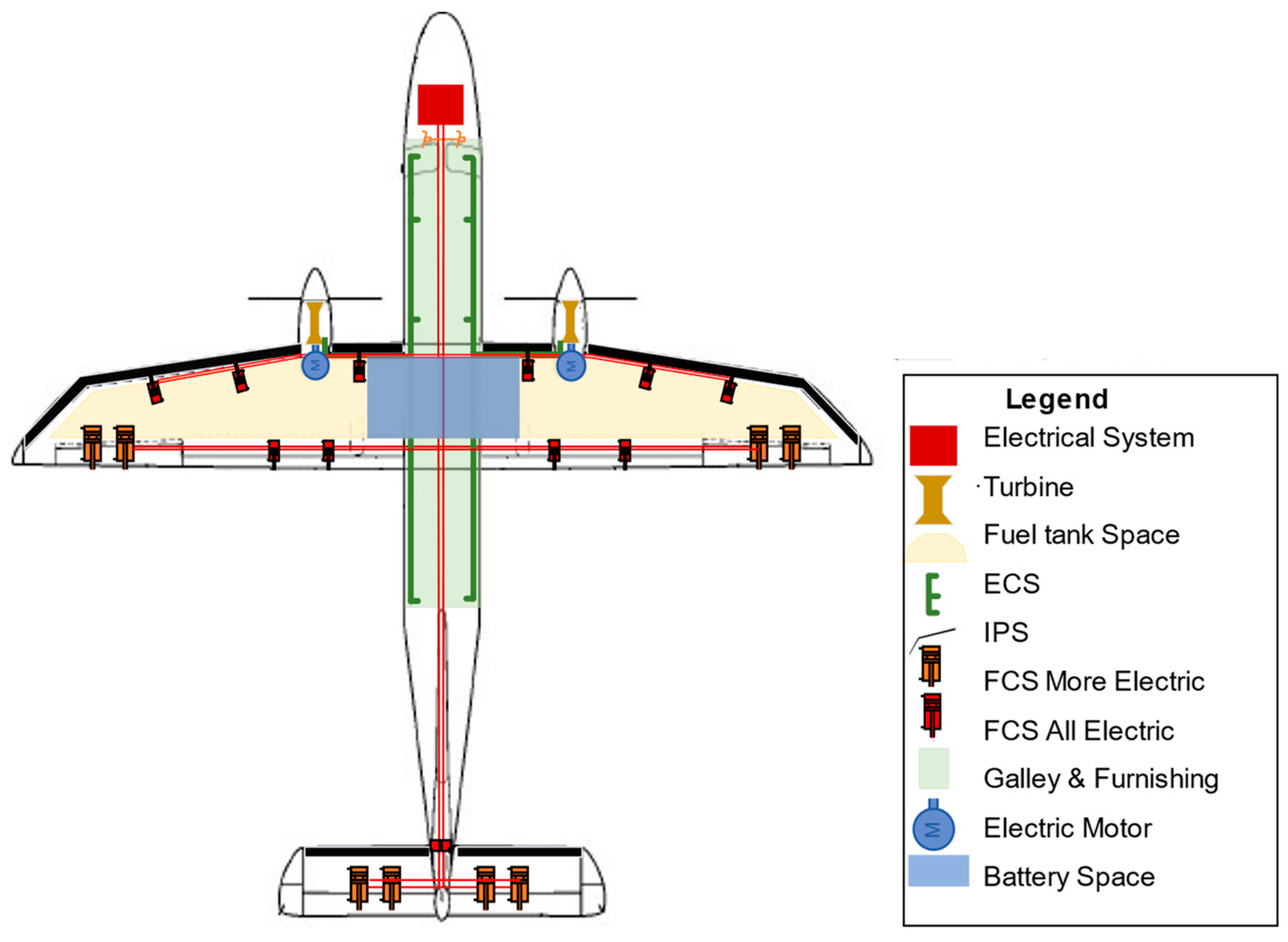
Figure 6 shows the electrified version of DO-228, and Table 5 presents the parameters of the key systems considered for the parametric analysis.
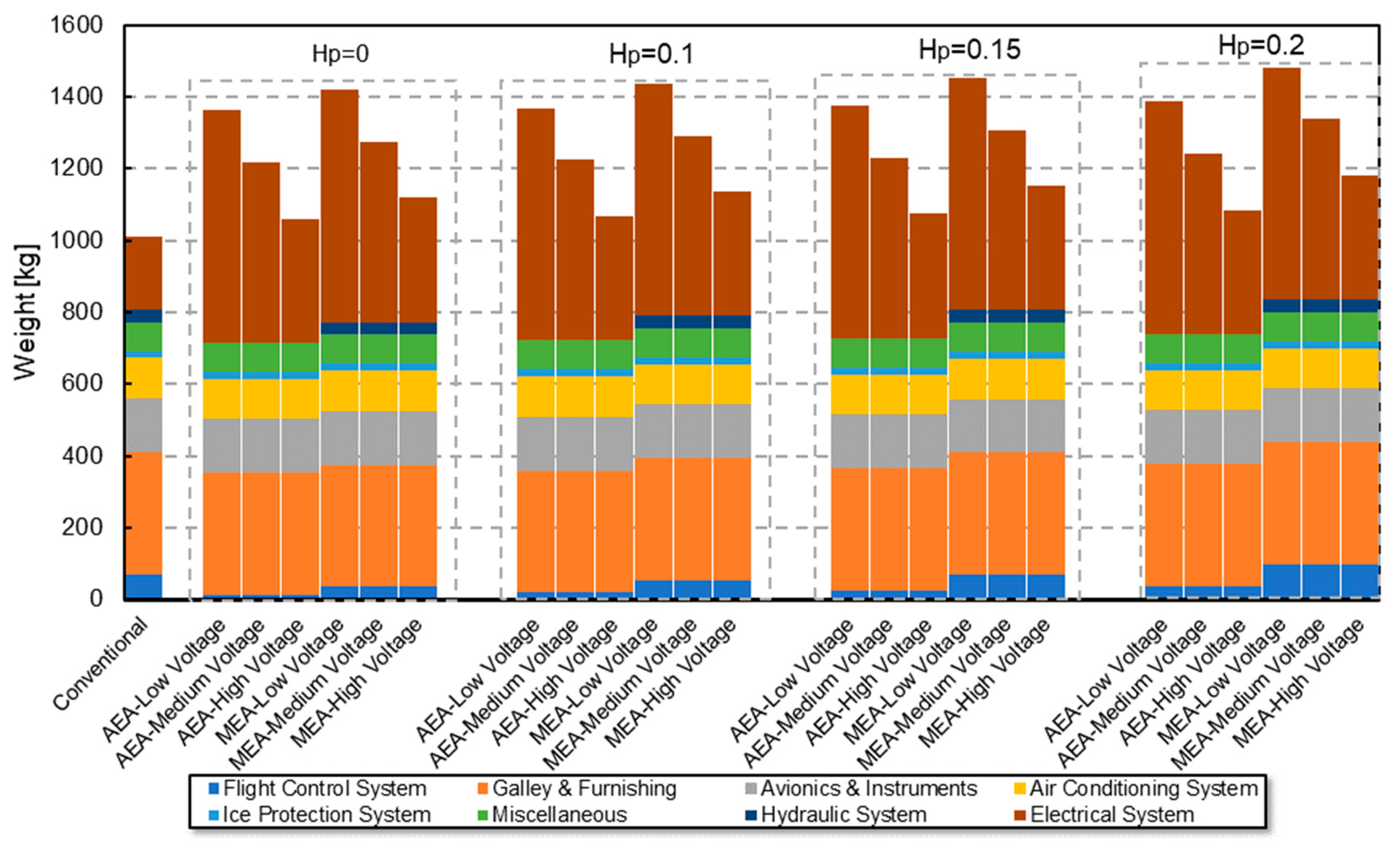
Figure 7 shows the impact of the electrification of the various subsystems on the system weight. The electrification of the aircraft leads to a systems weight increment compared to the conventional aircraft configuration.
The FCS weight reduction due to the elimination of the mechanical linkages is seen for the MEA and AEA architecture compared to the conventional configuration. The much heavier version of pneumatic boots is removed, saving significant weight in the IPS. However, the net increase in electrical power demand due to electrification along with added wiring significantly increases the electrical system weight. The electrified architectures with low-voltage power-consuming systems suffer from increased losses and require heavier feeders. Conversely, increasing the voltage levels leads to lighter feeders and reduces the overall weight of the electrical system. Within AEA and MEA architectures, FCS weight reduction occurs in AEA due to the application of EMAs, which are much lighter compared to other actuator types. The elimination of the centralized hydraulic system leads to a significant decrease in weight for the AEA architecture. Hence, a high-voltage AEA architecture is seen to be highly beneficial in a hybridized version of the aircraft.
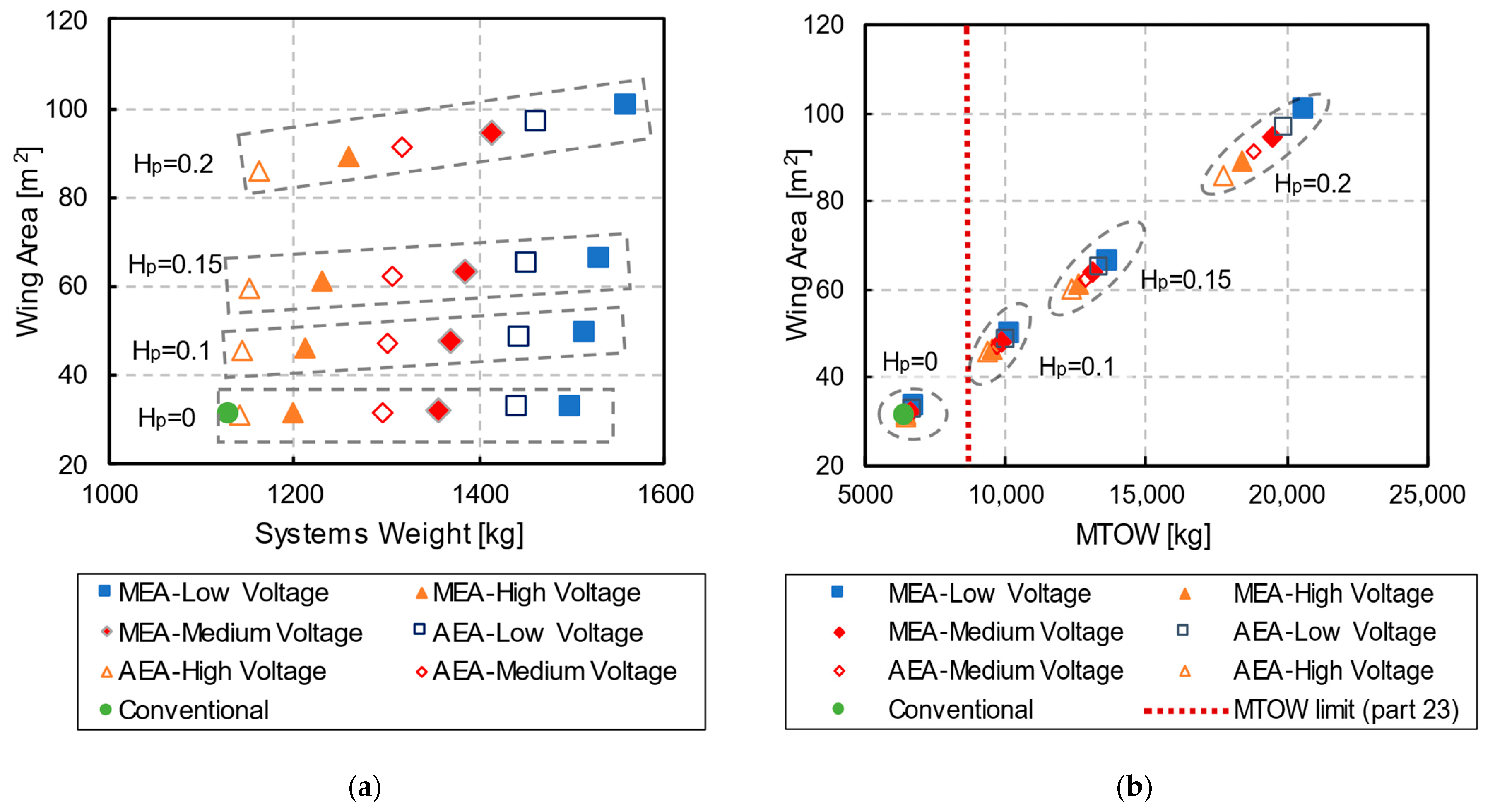
Figure 8 summarizes the results of the parametric study focusing on the variations in wing area and weight for today’s battery technology (Esp = 272 Wh/kg). Figure 8a shows the effect of the various parameter changes on the overall systems’ weight (output of Systems MDA module), and Figure 8b analyzes the effect of the same parameters on the MTOW. The overall MTOW increment due to hybridization is primarily due to the higher battery weight, which requires additional wing area to support the weight. The resulting increase in wing area, in addition to the electrification, leads to additional weight due to the systems. Furthermore, the rapid rise in MTOW between different hybridization levels is attributed to the so-called snowball effect, wherein the weight contribution of batteries leads to more power being required to carry out the mission, which further increases the aircraft’s empty weight and, therefore, the maximum takeoff weight. The large MTOWs of the hybrid-electric configuration exceed the weight limit for Part 23 certification. Furthermore, from a retrofitting perspective, a reduction in passengers and payload would be required to make these configurations feasible. Although it may be possible to envision retrofitting the aircraft with a larger wing, the additional weight will require strengthening the airframe structure, which carries a further weight penalty. These aspects are not explored within the scope of this study.
One can observe that for varying hybridization factors, the contribution of the system architecture follows the same trend: the MEA low-voltage architecture (solid blue square) is the heaviest architecture in each set, requiring the largest increase in wing area. On the other hand, AEA and MEA architectures with high-voltage architecture (orange triangles) seem to provide the lowest weight and required wing area increase.
Comparing the MEA and AEA configurations at low and high voltage levels shows that higher voltages lead to lower overall systems weight; this effect is also observable in the reduced required wing area. Furthermore, this effect is more pronounced at higher hybridization factors, implying that using higher voltage levels at a higher hybridization factor is worthwhile.
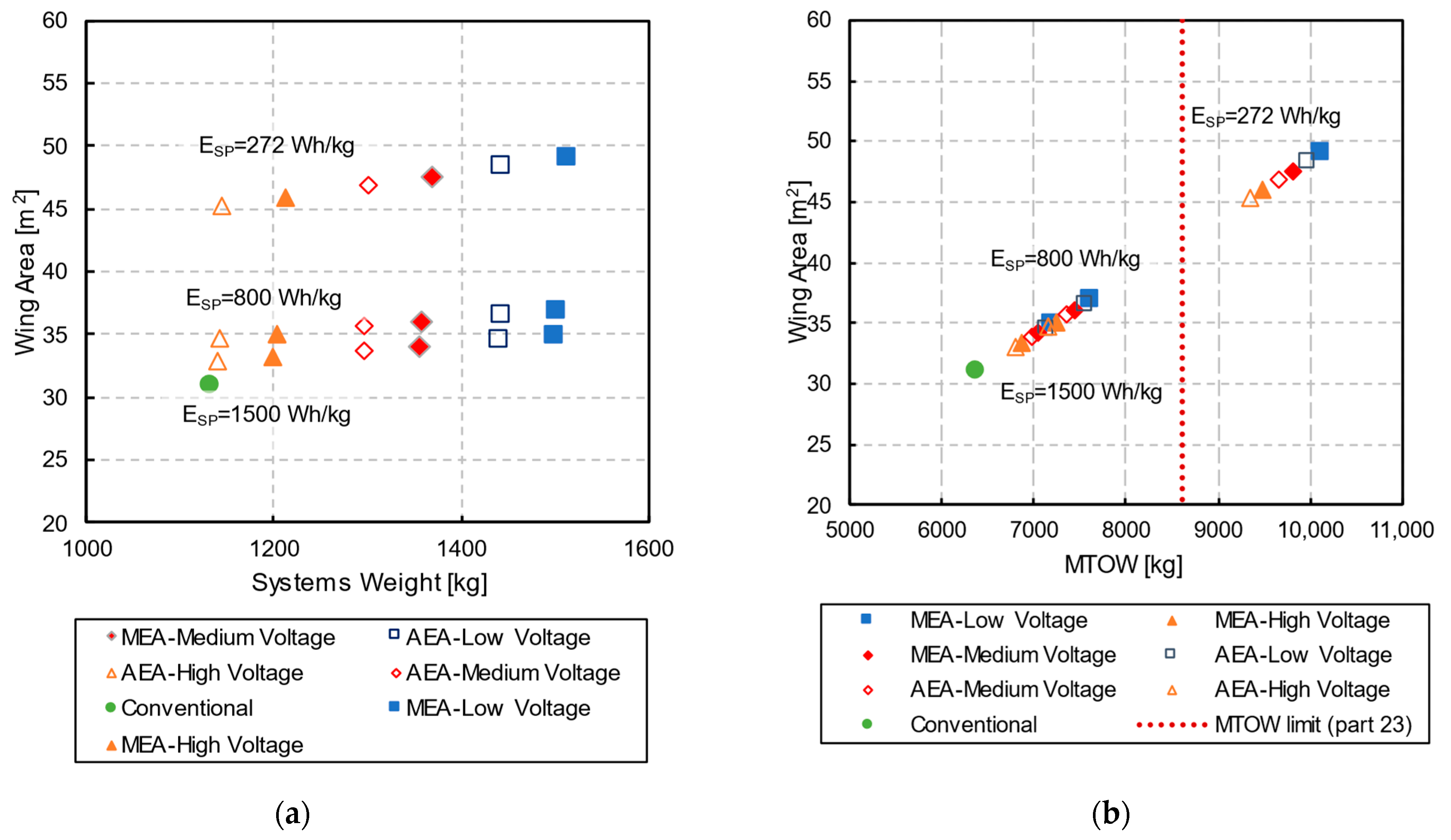
Figure 9 investigates the effect of varying battery energy density Esp in combination with the system electrification at aircraft-level parameters for a fixed hybridization factor (Hp = 0.1). Figure 9a,b show that increasing the battery energy density Esp helps to reduce the OWE increase (compared to a conventional system architecture) and thus helps the required increase in wing area to limit the increase in MTOW. However, even with very high Esp, the modified aircraft still requires a larger wing and has a higher MTOW than the conventional configuration.
However, to understand the overall impact of electrification on aircraft performance, the fuel burn change needs to be investigated, as discussed in Figure 10.
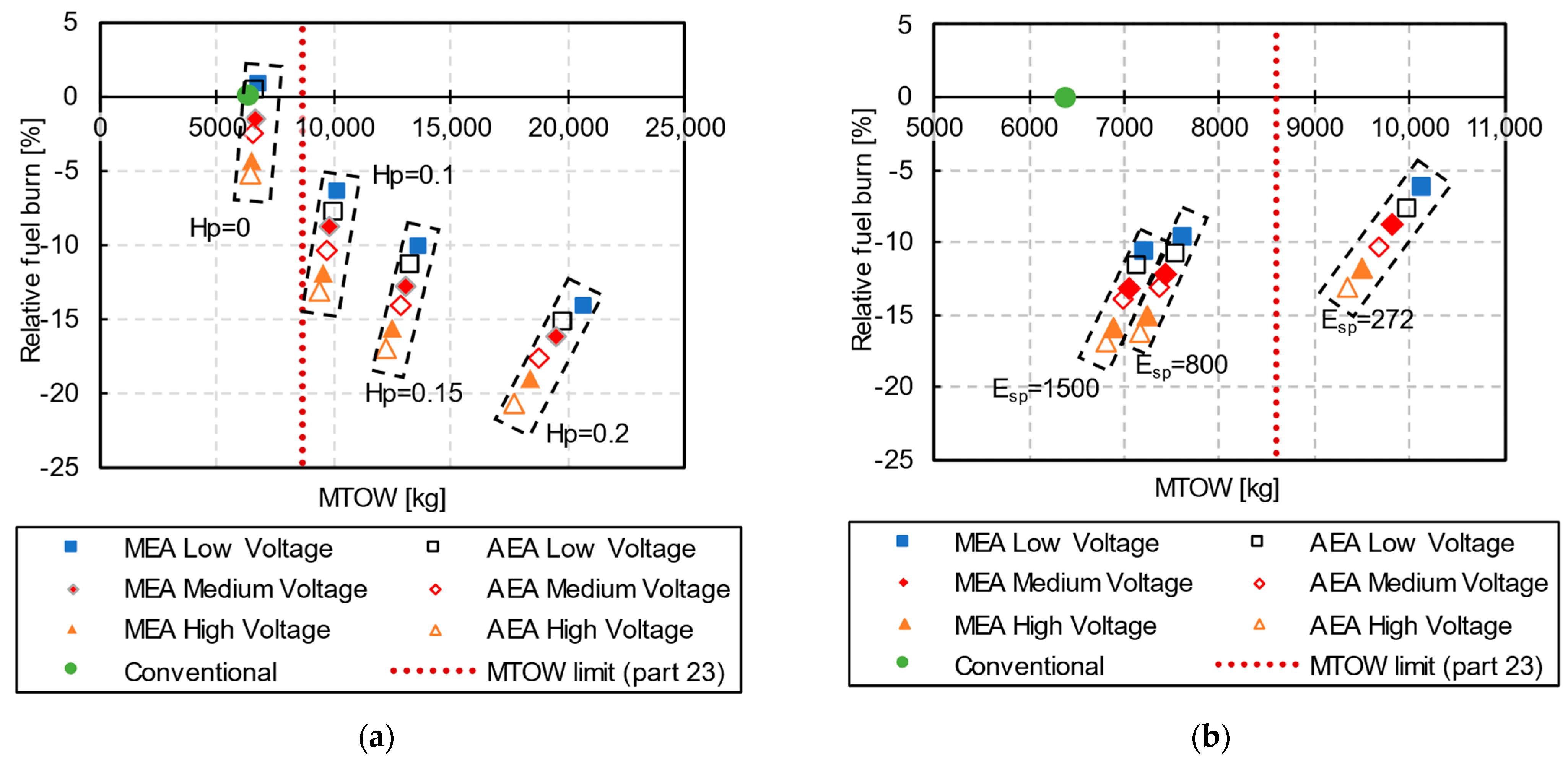
Figure 10 explores the effect of aircraft electrification on fuel burn. It has to be noted that the effect of additional drag due to aircraft electrification has not been considered in this case study. However, as the aircraft has a low cruise speed and only 19 passengers, the effect of additional drag due to the electrification of the bleed air system (using ram air instead of engine bleed) is negligible. Additionally, this study has not considered the effect of increased cooling requirements for electrification.
Figure 10a shows that even for a current battery Esp of 272 Wh/kg, only the low-voltage MEA system architectures will not reduce the mission fuel burn compared to the conventional configuration. The best system architectures are high-voltage AEA configurations. Still, with current Esp, even for the small hybridization of the aircraft (10%), the MTOW exceeds the limit of the Part 23 certification and is thus not viable for a retrofit including a wing area increase.
Figure 10b explores the impact of increasing Esp for a hybrid configuration with Hp = 0.1. One can see that all architectures with Esp = 800 Wh/kg and ESP = 1500 Wh/kg lead to configurations that meet the Part 23 MTOW limit and that lead to potential fuel burn reductions of 10% and more.

6. Conclusions

This paper presents an MDA framework for system integration within aircraft conceptual design for conventional, hybrid-electric, and more electric aircraft. A generic MDA workflow is presented that can be easily adapted to future aircraft and system configurations. The subsystem models cover different technologies and the validity range for smaller aircraft (commuter, business, and regional). The overall validation of the Systems MDA attests to an error range that is acceptable for conceptual design, considering the limited availability of validation data for more electric and all-electric aircraft systems.
The framework’s capabilities are demonstrated with a case study: the evaluation of the effect of the simultaneous hybridization and electrification of a Dornier DO-228 aircraft. A parametric study of the aircraft hybridization factor, the system architecture electrification levels, and subsystem technologies, i.e., the voltage level in the electrical power system, and varying battery energy densities illustrate the framework’s functionality.
By focusing on the aircraft weight and mission fuel burn, the results suggest that when working with higher hybridization factors, the subsystem voltage levels should be increased to reduce the weight of the overall system. However, comparing the MEA and AEA cases, additional parameters must be considered to further evaluate the most suitable architecture to decrease the environmental impact or enable economically viable retrofitting.
The framework provides meaningful insight into the relationships between aircraft-level design choices and system and subsystem cascading impacts. In addition, the presented framework provides an integration sandbox for more advanced system analysis, such as safety analysis, thermal analysis, and maintenance analysis [65,66].
Future study will focus on expanding the framework to represent all necessary subsystems with sufficient detail to capture the effects of secondary power off-take in hybrid-electric configurations, the drag penalty due to increased ventilation flow requirements in electrified aircraft, and to better capture the changes in the propulsion subsystem.
Although the AEA systems architecture considers eliminating the hydraulic components, additional safety inputs are required to evaluate the architecture. Hence, the integration of systems safety parameters will be considered in the near future. Although the systems sizing workflow applies physics-based modeling to the flight control and electrical systems they still incur error propagation through multiple sources. The integration of error propagation and uncertainty analysis is crucial for obtaining a better understanding of the results with data that cannot be validated (as projected in the future).
Overall, the research presented in this paper contributes to closing the gap in conceptual design tools for feasibility studies of hybrid-electric aircraft, including the analysis of the viability of the retrofitting potential of existing aircraft. Therefore, the presented study supports accelerating the development of more environmentally friendly aircraft.

Author Contributions

Conceptualization, V.M., A.K.J. and S.L.-H.; methodology, V.M., A.K.J. and S.L.-H.; software, V.M.; validation, V.M., A.K.J. and S.L.-H.; formal analysis, V.M.; investigation, V.M.; resources, S.L.-H.; data curation, V.M.; writing—original draft preparation, V.M. and A.K.J.; writing—review and editing, V.M., A.K.J. and S.L.-H.; visualization, V.M., A.K.J. and S.L.-H.; supervision, S.L.-H.; project administration, S.L.-H.; funding acquisition, S.L.-H. All authors have read and agreed to the published version of the manuscript.

Funding

This research received funding from the following sources: Grant Number RGPIN 5515-2019 from the Natural Sciences and Engineering Research Council of Canada (NSERC); Grant Number CRDPJ 538897-19 funded by the Natural Sciences and Engineering Research Council of Canada (NSERC), the Consortium de recherche et d’innovation en aérospatiale au Québec (CRIAQ), and Bombardier. The presented article also benefited from the authors’ collaboration within the AGILE4.0 project, which receives funding from the European Union’s Horizon 2020 research and innovation program under grant agreement No 815122.

Data Availability Statement

The data presented in this study are available on request from the corresponding authors.

Acknowledgments

We acknowledge the tool support provided by Gala Licheva and Zachary Heit.

Conflicts of Interest

The authors declare no conflict of interest.

Appendix A

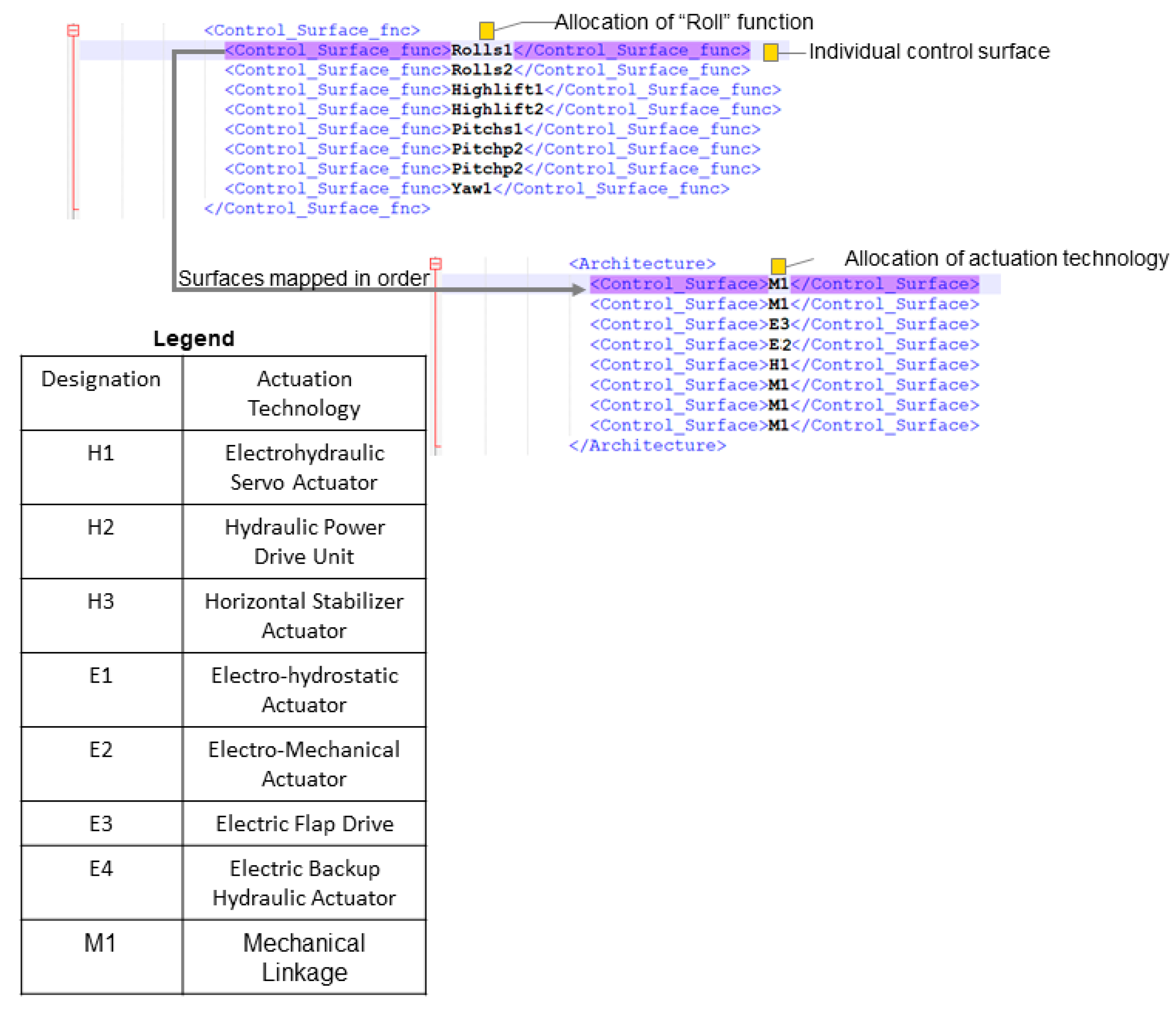
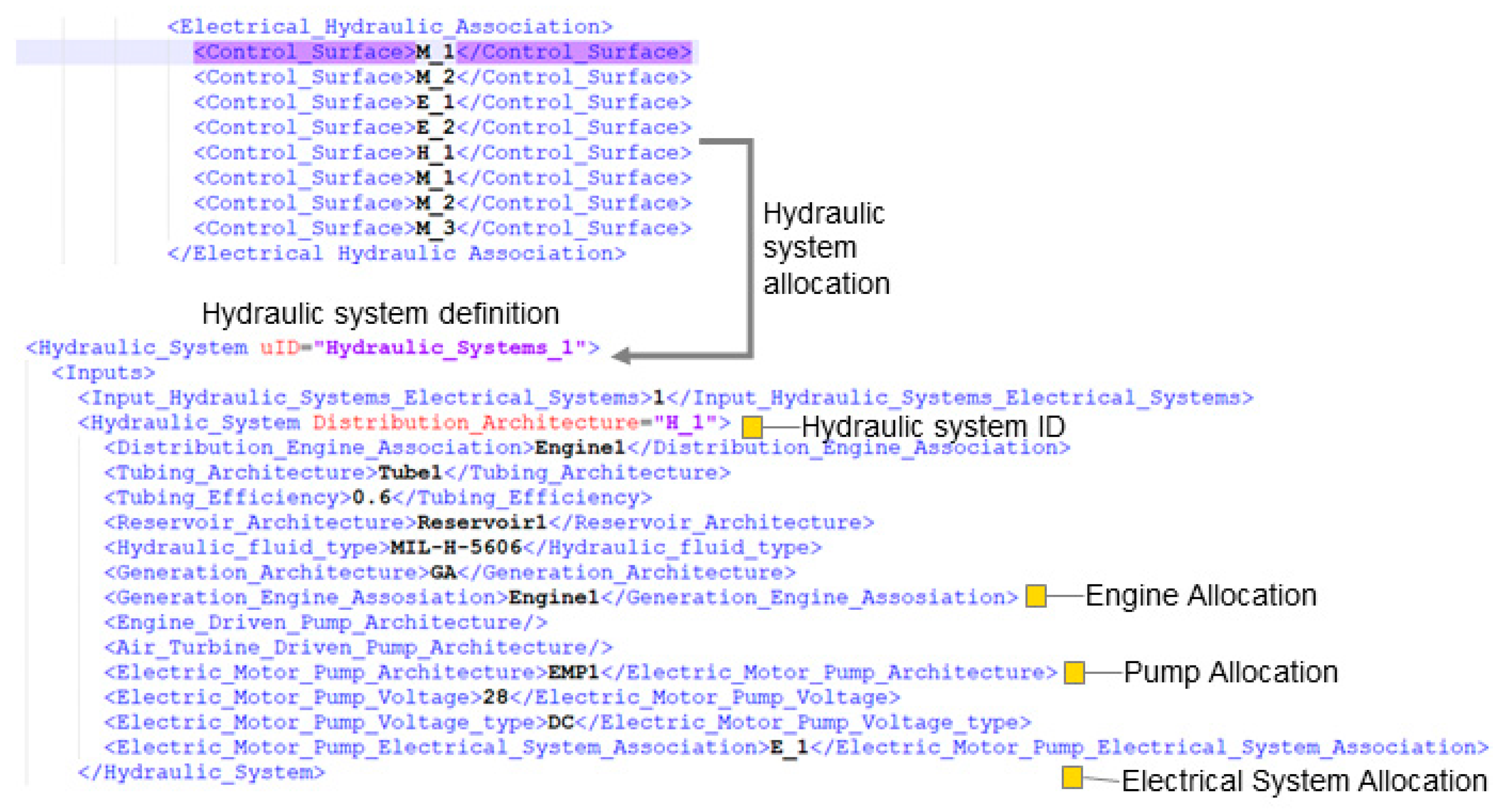
This section shows the Systems MDA descriptor and highlights important definitions and allocation syntax using descriptors from an FCS and an environmental control system architecture.
Figure A1. Definition of control surfaces and assignment of functions and actuators for a FCS using the System MDA descriptor.
Aerospace 10 00533 g0a1
Figure A2. Allocation and definition of a hydraulic power system to a specific control surface actuator.
Aerospace 10 00533 g0a2
Figure A3. Allocation and definition of an electrical power system to a specific control surface actuator.
Aerospace 10 00533 g0a3
Figure A4. Definition of air conditioning packs within an environmental control system architecture.
Aerospace 10 00533 g0a4

Appendix B

Table A1. Electric power consumer demand.
SubsystemPower Demand
Lights P L i g , n o m = 0.31 L f u s e l a g e (1)
Avionics and Instruments P A v , i n s t t a x i =  0.612 e 0.048   L f u s e l a g e (2)
P A v i n s t n o m = 0.02   L f u s e l a g e 1.55 (3)
Ice Protection i P i p s , n o m = 0.035   s w + 2.02 (4)
Air-conditioning [67] ii P a c , n o m = 0.077   V c a b i n 0.40 (5)
Fuel System iii P F S , n o m =  2.88   e 0.0399 L f u s e l a g e N e n g (6)
i This does not include electric de-icing system. Electric de-icing power demand can be considered to be 5% P i p s , n o m . ii This power demand corresponds to conventional aircraft air-conditioning units electrical power demand. iii The Fuel System power demands are estimated using this equation whereas the Fuel System weights are obtained using the physics-based methods described in [51].
Table A2. Control surface deflection.
Control Surface TypeControl Surface FunctionSurface Deflection Rate (deg/s)
Aileron, Spoiler Roll60
SpoilerAirbrake30
Flaps, SlatsHigh-lift10
RudderYaw40
ElevatorPitch60
Horizontal StabilizerPitch trim0.5
Table A3. Control surface usage factor.
Control Surface TypeControl Surface FunctionGroundTaxiTakeoffClimbCruiseDescentApproachLanding
Aileron, SpoilerRoll0.330.3301110.330.33
SpoilerAutobrake0.330.33011100.33
Flaps, SlatsHigh-lift01000100
RudderYaw0.330.330.330.330.330.50.50.33
Elevator, Horizontal StabilizerPitch00110.1510.331
Table A4. Subsystem P/W ratio.
SubsystemP/W RatioRef.SubsystemP/W RatioRef.
HMA0.4 k W / k g [66]EDP4.6 k W / k g [52]
EHSA0.2 k W / k g [66]HMG0.46 k W / k g [53]
EHA0.2 k W / k g [66]Actuator Power Electronics2 k W / k g [67]
EMA0.40 k W / k g [68]EMP0.4 k W / k g [52]
Hydraulic Power Drive0.043 k W / k g [69]AC Generator1.3 k V A / k g [70]
Electric Motor Power Drive0.045 k W / k g [69]DC Generator0.5 k W / k g [70]
THSA0.045 k W / k g [52]EBHA0.13 k W / k g [66]
Table A5. Aircraft parameters.
Aircraft ParameterValueAircraft ParameterValue
Wing span [ m ] 16.97Number of passengers19
Payload [kg]1959.9Number of crew2
Range [ m ]395,935.2Hybrid propulsion architectureParallel
Mach0.4Service ceiling [ft]25,000
Aspect ratio9.0Hydraulic system pressure [ p s i ] 3000
Length [ m ] 16.56Generation voltage [ V ] 230
Cabin volume [ m 3 ] 14.7Generation voltage typeAC
Number of engines2Inverter voltage [ V ] 115
Propeller diameter [ m ] 2.73Wing area [ m 2 ] 32
Fuselage length [ m ]16.56Fuselage width [ m ] 1.346
Vertical stab length [ m ]2.63Horizontal tail length [ m ] 6.45
Engine configuration Wing mountedDiameter of engine [ m ] 0.98
Length of engine [ m ]2.76
Table A6. Conventional vs. hybridized aircraft systems architecture.
ParameterConventionalHp = 0.1
FCS primary flight control actuatorMechanicalEHA, EHSA
FCS secondary flight control actuatorMechanicalAll EMA
Power converterDCAC, DCDCACDC, ACAC
FCS voltage (V)2828
FCS voltage typeDCDC
Avionics voltage (V)2828
FCS voltage typeDCDC
Other systems voltage (V)115230
Other systems voltage typeACAC
Electrical generation voltage (V)28230
Electrical generation voltage typeDCAC
Table A7. Subsystem power demand ratios iv.
Flight PhaseGroundTaxiTakeoffClimbCruiseDescentApproachLanding
Subsystem
Galley, Entertainment, Furnishing0.461.03111.090.720.720.72
Lights0.9450.75110.9431.191.191.07
Avionics, Instruments0.25 v1 vi111111
Ice Protection0.330.330.330.330.330.50.50.33
Air-conditioning111.06111.061.060.92
Fuel System00110.1510.331
iv Unless specified P n o r m is to be used with factors to estimate power demand per flight phase; v Factor to be used with Equation (20); vi Factor to be used with Equation (20).

References

  1. Bruner, S.; Baber, S.; Harris, C.; Caldwell, N.; Keding, P.; Rahrig, K.; Pho, L.; Wlezian, R. NASA N+3 Subsonic Fixed Wing Silent Efficient Low-Emissions Commercial Transport (SELECT) Vehicle Study Revision A; National Aeronautics and Space Administration: Washington, DC, USA, 2010. Available online: https://ntrs.nasa.gov/api/citations/20100042399/downloads/20100042399.pdf (accessed on 17 May 2023).
  2. Collier, F.; Wahls, R. NASA Aeronautics Strategic Implementation Plan Strategic Thrust 3A Roadmap Overview Ultra-Efficient Commercial Vehicles-Subsonic Transports; NASA Aeronautics Research Mission Directorate, National Aeronautics and Space Administration: Washington, DC, USA, 2016. Available online: https://nari.arc.nasa.gov/sites/default/files/attachments/Thrust%203a_1june2016-web.pdf (accessed on 17 May 2023).
  3. International Civil Aviation Organization (ICAO). Electric and Hybrid Aircraft Platform for Innovation (E-HAPI). Available online: https://www.icao.int/environmental-protection/Pages/electric-aircraft.aspx (accessed on 17 May 2023).
  4. Charles, A. Faradair Establishes Duxford HQ for Hybrid Electric STOL. Available online: https://www.ainonline.com/aviation-news/aerospace/2020-07-16/faradair-establishes-duxford-hq-hybrid-electric-stol (accessed on 16 July 2020).
  5. Pullen, J. Raytheon Technologies Completes First Engine Run of Hybrid-Electric Demonstrator. Available online: https://www.aviationtoday.com/2023/01/04/raytheon-technologies-completes-first-engine-run-hybrid-electric-demonstrator/ (accessed on 17 May 2023).
  6. Bradley, M.K.; Droney, C.K. Subsonic Ultra Green Aircraft Research: Phase II—Volume II—Hybrid Electric Design Exploration. No. NASA/CR 2015, 4, 2015–21870. [Google Scholar]
  7. Jansen, R.; Bowman, C.; Jankovsky, A.; Dyson, R.; Felder, J. Overview of NASA Electrified Aircraft Propulsion Research for Large Subsonic Transports. In Proceedings of the 53rd AIAA/SAE/ASEE Joint Propulsion Conference, Atlanta, GA, USA, 10–12 July 2017. [Google Scholar]
  8. Juretzko, P.G.; Immer, M.; Wildi, J. Performance Analysis of a Hybrid-Electric Retrofit of a RUAG Dornier Do 228NG. CEAS Aeronaut. J. 2020, 11, 1. [Google Scholar] [CrossRef]
  9. Hofmann, J.P.; Stumpf, E.; Weintraub, D.; Köhler, J.; Pham, D.; Schneider, M.; Dickhoff, J.; Burkhart, B.; Reiner, G.; Spiller, M.; et al. A Comprehensive Approach to the Assessment of a Hybrid Electric Powertrain for Commuter Aircraft. In Proceedings of the AIAA Aviation Forum, Dallas, TX, USA, 17–21 June 2019; pp. 1–16. [Google Scholar]
  10. Jeyaraj, A.K.; Liscouët-Hanke, S. A Safety-Focused System Architecting Framework for the Conceptual Design of Aircraft Systems. Aerospace 2022, 9, 791. [Google Scholar] [CrossRef]
  11. Sanchez, F.; Huzaifa, A.M.; Liscouët-Hanke, S. Ventilation Considerations for an Enhanced Thermal Risk Prediction in Aircraft Conceptual Design. Aerosp. Sci. Technol. 2021, 108, 106401. [Google Scholar] [CrossRef]
  12. Jan, R. Airplane Design; Roskam Aviation and Engineering Corporation: Lawrence, Kansas, 1985; Volume 4, ISBN 188488542X. [Google Scholar]
  13. Torenbeek, E. Synthesis of Subsonic Airplane Design; Delft University Press: Delft, The Netherlands, 1982. [Google Scholar]
  14. Raymer, D. Aircraft Design: A Conceptual Approach; AIAA Education Series: Washington, DC, USA, 1989; ISBN 0-930403-51-7. [Google Scholar]
  15. Wells, D.P.; Horvath, B.L.; McCullers, L.A. The Flight Optimization System Weight Estimation Method. NASA Tech. Memo. 2017, 1, 219627. [Google Scholar]
  16. Koeppen, C.; Carl, U.B. Kopplungen Und Sensitivitäten Des Einflusses Von Systemen Auf Den Flugzeugentwurf; DGLR: Bonn, Germany, 2003; Volume 11. [Google Scholar]
  17. Liscouët-Hanke, S.A. Model-Based Methodology for Integrated Preliminary Sizing and Analysis of Aircraft Power System Architectures. Ph.D. Dissertation, Institut National des Sciences Appliquée Toulouse, Toulouse, France, 2008. [Google Scholar]
  18. Lammering, T. Integration of Aircraft Systems into Conceptual Design Synthesis. Ph.D. Dissertation, RTWH Aachen, Aachen, Germany, 2014. [Google Scholar]
  19. Chakraborty, I. Subsystem Architecture Sizing and Analysis for Aircraft Conceptual Design. Ph.D. Dissertation, Georgia Institute of Technology, Atlanta, Georgia, 2015. [Google Scholar]
  20. Chiesa, S.; Fioriti, M.; Viol, N. Methodology for an Integrated Definition of a System and Its Subsystems: The Case-Study of an Airplane and Its Subsystems. In Systems Engineering—Practice and Theory; IntechOpen: London, UK, 2012. [Google Scholar]
  21. Boggero, L.; Fioriti, M.; Corpino, S.; Ciampa, P.D. Onboard Systems Preliminary Sizing in an Overall Aircraft Design Environment. In Proceedings of the 17th AIAA Aviation Technology, Integration, and Operations Conference, Denver, Colorado, 5–9 June 2017. [Google Scholar]
  22. Jünemann, M.; Thielecke, F.; Peter, F.; Hornung, M.; Schültke, F.; Stumpf, E. Methodology for Design and Evaluation of More Electric Aircraft Systems Architectures within the AVACON Project. Dtsch. Luft- Und Raumfahrtkongress 2019, 1–18. [Google Scholar] [CrossRef]
  23. Fioriti, M.; Della Vecchia, P.; Donelli, G.; Hansmann, P. Assessing the Integration of Electrified Onboard Systems in an MDAO Framework for a Small Transport Aircraft. In Proceedings of the AIAA Aviation Forum 2021, AIAA 2021-9094, Online, 2–6 August 2021. [Google Scholar] [CrossRef]
  24. Liscouët-Hanke, S.; Huynh, K. A Methodology for Systems Integration in Aircraft Conceptual Design—Estimation of Required Space. SAE Tech. Pap. 2013, 7, 2013. [Google Scholar]
  25. Brelje, B.J.; Martins, J.R.R.A. Electric, Hybrid, and Turboelectric Fixed-Wing Aircraft: A Review of Concepts, Models, and Design Approaches. Prog. Aerosp. Sci. 2019, 104, 1–19. [Google Scholar] [CrossRef]
  26. Hoogreef, M.F.M.; Vos, R.; de Vries, R.; Veldhuis, L.L.M. Conceptual Assessment of Hybrid Electric Aircraft with Distributed Propulsion and Boosted Turbofans. In Proceedings of the AIAA Scitech Forum, San Diego, CA, USA, 7–11 January 2019. [Google Scholar] [CrossRef] [Green Version]
  27. Zamboni, J.; Vos, R.; Emeneth, M.; Schneegans, A. A Method for the Conceptual Design of Hybrid Electric Aircraft. In Proceedings of the AIAA Scitech Forum, San Diego, CA, USA, 7–11 January 2019. [Google Scholar] [CrossRef] [Green Version]
  28. Köhler, J.; Jeschke, P. Conceptual Design and Comparison of Hybrid Electric Propulsion Systems for Small Aircraft. CEAS Aeronaut. J. 2021, 12, 907–922. [Google Scholar] [CrossRef]
  29. Finger, D.F.; Bil, C.; Braun, C. Initial Sizing Methodology for Hybrid-Electric General Aviation Aircraft. J. Aircr. 2020, 57, 2. [Google Scholar] [CrossRef]
  30. de Vries, R.; Brown, M.; Vos, R. Preliminary Sizing Method for Hybrid-Electric Distributed-Propulsion Aircraft. J. Aircr. 2019, 56, 6. [Google Scholar] [CrossRef]
  31. Zumegen, C.; Strathoff, P.; Stumpf, E.; Wensveen, J.V.; Rischmüller, C.; Hornung, M.; Geiß, I.; Strohmayer, A. Technology Selection for Holistic Analysis of Hybrid-Electric Commuter Aircraft. CEAS Aeronaut. J. 2022, 13, 597–610. [Google Scholar] [CrossRef]
  32. Nasoulis, C.P.; Protopapadakis, G.; Gkoutzamanis, V.G.; Kalfas, A.I. The Impact of Propulsive Architecture on the Design of a 19-Passenger Hybrid-Electric Aircraft. IOP Conf. Ser. Mater. Sci. Eng. 2022, 1226, 12074. [Google Scholar] [CrossRef]
  33. Gkoutzamanis, V.G.; Tsentis, S.E.; Valsamis Mylonas, O.S.; Kalfas, A.I.; Kyprianidis, K.G.; Tsirikoglou, P.; Sielemann, M. Thermal Management System Considerations for a Hybrid-Electric Commuter Aircraft. J. Thermophys. Heat Transf. 2022, 36, 650–666. [Google Scholar] [CrossRef]
  34. Cinar, G. A Methodology for Dynamic Sizing of Electric Power Generation and Distribution Architectures. Ph.D. Dissertation, Georgia Institute of Technology, Atlanta, GA, USA, 2018. [Google Scholar]
  35. Cinar, G.; Garcia, E.; Mavris, D.N. A Framework for Electrified Propulsion Architecture and Operation Analysis. Aircr. Eng. Aerosp. Technol. 2020, 92, 675–684. [Google Scholar] [CrossRef]
  36. Cinar, G.; Cai, Y.; Bendarkar, M.V.; Burrell, A.I.; Denney, R.K.; Mavris, D.N. System Analysis and Design Space Exploration of Regional Aircraft with Electrified Powertrains. In Proceedings of the AIAA SciTech Forum, San Diego, CA, USA, 3–7 January 2022. [Google Scholar]
  37. Cai, Y.; Pastra, C.L.; Xie, J.; Thind, J.K.; Monjon, M.M.; Gladin, J.C.; Mavris, D.N. System-Level Trade Study of Hybrid Parallel Propulsion Architectures on Future Regional and Thin Haul Turboprop Aircraft. In Proceedings of the AIAA Scitech Forum, National Harbour, MD, USA, 23–27 January 2023. [Google Scholar]
  38. Gray, J.; Moore, K.; Hearn, T.; Naylor, B. A Standard Platform for Testing and Comparison of MDAO Architectures. In Proceedings of the 53rd AIAA Structures, Structural Dynamics, and Materials (SDM) Conference, Honolulu, HI, USA, 23–26 April 2012; p. 53. [Google Scholar]
  39. Chakraborty, I.; Mavris, D.N.; Emeneth, M.; Schneegans, A. An Integrated Approach to Vehicle and Subsystem Sizing and Analysis for Novel Subsystem Architectures. Proc. Inst. Mech. Eng. Part G J. Aerosp. Eng. 2016, 230, 496–514. [Google Scholar] [CrossRef]
  40. Harish, A.; Gladin, J.; Mavris, D. Framework for Design Space Exploration of Novel Propulsion System Architectures. In Proceedings of the AIAA Scitech Forum, Orlando, FL, USA, 6–10 January 2020. 1 PartF. [Google Scholar] [CrossRef]
  41. Alder, M.; Moerland, E.; Jepsen, J.; Nagel, B. Recent Advances in Establishing a Common Language for Aircraft Design with CPACS. In Proceedings of the Aerospace Europe Conference, Bordeaux, Frankreich, 25–28 February 2020. [Google Scholar]
  42. Rodriguez, C.D.; Liscouët-Hanke, S. Architecture-Based Fuel System Conceptual Design Tool for Hybrid-Electric Aircraft. In Proceedings of the AIAA Aviat. Forum, Virtual, 2–6 August 2021. [Google Scholar]
  43. Heit, Z.; Liscouet-Hanke, S. Estimation of Battery Pack Layout and Dimensions for the Conceptual Design of Hybrid-Electric Aircraft. In Proceedings of the AIAA SciTech Forum, National Harbour, MD, USA, 23–27 January 2023. [Google Scholar]
  44. Boden, B.; Flink, J.; Först, N.; Mischke, R.; Schaffert, K.; Weinert, A.; Wohlan, A.; Schreiber, A.R.C.E. An Integration Environment for Engineering and Science. SoftwareX 2021, 15. [Google Scholar] [CrossRef]
  45. Licheva, G.; Liscouet-Hanke, S. A Conceptual Sizing Tool for Regional and Commuter Aircraft with Hybrid-Electric Propulsion. In Proceedings of the AIAA SciTech Forum, National Harbour, MD, USA, 23–27 January 2023. [Google Scholar]
  46. William, J.E.; Vukelich, S.R. The USAF Stability and Control Digital DATCOM Volume I, Users Manual; McDonnell Douglas Astronautics Company: St. Louis, MO, USA, 1979; Available online: https://apps.dtic.mil/sti/pdfs/ADA086557.pdf (accessed on 12 September 2020).
  47. Anderson, R.D.; Flora, C.C.; Nelson, R.M.; Raymond, E.T.; Vincent, J.H. Development of Weight and Cost Estimates for Lifting Surfaces with Active Controls; NASA Tech. Rep. N76-20150; Boeing Commercial Airplane Company: Seattle, DC, USA, 1979. Available online: https://ntrs.nasa.gov/api/citations/19760013062/downloads/19760013062.pdf (accessed on 12 September 2020).
  48. SAE International. Mechanical Control Design Guide; SAE International: Warrendale, PA, USA, 2012; Volume 5770. [Google Scholar]
  49. SAE International. Commercial Aircraft Hydraulic System Sizing; SAE International: Warrendale, PA, USA, 2021. [Google Scholar]
  50. SAE International. Fundamentals in Wire Selection and Sizing for Aerospace Applications—AIR6540; SAE International: Warrendale, PA, USA, 2019. [Google Scholar]
  51. SAE International. Aerospace Vehicle Wiring—AS50881; SAE International: Warrendale, PA, USA, 1998. [Google Scholar]
  52. Brombach, J.; Schröter, T.; Lücken, A.; Schulz, D. Optimized Cabin Power Supply with a +/− 270 v DC Grid on a Modern Aircraft. In Proceedings of the 2011 7th International Conference-Workshop Compatibility and Power Electronics, CPE 2011, Tallinn, Estonia, 1–3 June 2011; pp. 425–428. [Google Scholar]
  53. Brombach, J.; Schröter, T.; Lücken, A.; Schulz, D. Optimizing the Weight of an Aircraft Power Supply System through a +/− 270 Vdc Main Voltage. Prz. Elektrote. 2012, 88, 47–50. [Google Scholar]
  54. Esdras, G.F.; Liscouët-Hanke, S. An Electrical Load Estimation Tool for Aircraft Conceptual Design. SAE Tech. Pap. 2013, 7. [Google Scholar] [CrossRef]
  55. SAE International. Aircraft Fuel Weight Penalty Due to Air Conditioning—AIR1168/6A; SAE International: Warrendale, PA, USA, 2011. [Google Scholar]
  56. Allan, S.; Ian, M. Design and Development of Aircraft Systems, 3rd ed.; John Wiley & Sons Ltd.: Hoboken, NJ, USA, 2020; ISBN 978-1-119-61150-9. [Google Scholar]
  57. Scholz, D.; Seresinhe, R.; Staack, I.; Lawson, C. Fuel Consumption Due To Shaft Power Off-Takes From the Engine. In Proceedings of the 4th International Workshop on Aircraft System Technologies (AST 2013), Hamburg, Germany, 23–24 April 2013; pp. 169–179. [Google Scholar]
  58. Taylor, J.W.R. Jane’s All the World’s Aircraft 1982–1983; Janes Information Services: Croydon, UK, 1982. [Google Scholar]
  59. Limited, H.A. Technical Specification for HAL-Dornier-228-202 Aircraft System; Transport Aircraft Division: Banglore, India, 2014. [Google Scholar]
  60. Mohan, V.; Jeyaraj, A.; Liscouët-Hanke, S. Systems Integration Considerations for Hybrid-Electric Commuter Aircraft: Case Study for the DO-228. In Proceedings of the AIAA Scitech Forum, National Harbour, MD, USA, 23–27 January 2023. [Google Scholar]
  61. Finger, D.F.; de Vries, R.; Vos, R.; Braun, C.; Bil, C. Cross-Validation of Hybrid-Electric Aircraft Sizing Methods. J. Aircr. 2022, 59, 742–760. [Google Scholar] [CrossRef]
  62. Eftekhari, A. On the Theoretical Capacity/Energy of Lithium Batteries and Their Counterparts. ACS Sustain. Chem. Eng. 2019, 7, 3684–3687. [Google Scholar] [CrossRef]
  63. Sélim, S.; Liscouët-Hanke, S.; Tfaily, A.; Butt, A.; Alphonso, B. Scoring Approach to Assess Maintenance Risk for Aircraft Systems in Conceptual Design. J. Aircr. 2023, 1–11, Article in Advance. [Google Scholar] [CrossRef]
  64. Vladimirov, S.V.; Forde, S. Demonstration Program to Design, Manufacture and Test an Autonomous Electro-Hydrostatic Actuator to Gimbal Large Booster-Class Engines. In Proceedings of the 42nd AIAA/ASME/SAE/ASEE Joint Propulsion Conference & Exhibit, Sacramento, CA, USA, 9–12 July 2006; Volume 1, pp. 541–546. [Google Scholar] [CrossRef]
  65. Maré, J.-C. Aerospace Actuators 3; John Wiley & Sons: Hoboken, NJ, USA, 2018; ISBN 9781848219434. [Google Scholar]
  66. Eaton. Eaton’s Aerospace Product Capabilities in A320/321. Available online: https://www.eaton.com/content/dam/eaton/markets/aerospace/Airbus-A318-A319-A320-A321-capabilities-brochure.pdf (accessed on 17 May 2023).
  67. Postnikov, S.E.; Trofimov, A.A.; Baikov, S.V. Architecture Options Estimate for the Near-Medium-Haul Aircraft Control System by the Reliability, Mass and Power Consumption Criteria. Aerosp. Syst. 2019, 2, 33–40. [Google Scholar] [CrossRef] [Green Version]
  68. Qiao, G.; Liu, G.; Shi, Z.; Wang, Y.; Ma, S.; Lim, T.C. A Review of Electromechanical Actuators for More/All Electric Aircraft Systems. Proc. Inst. Mech. Eng. Part C J. Mech. Eng. Sci. 2018, 232, 4128–4151. [Google Scholar] [CrossRef] [Green Version]
  69. Zaccai, D.; Bertels, F.; Vos, R. Design Methodology for Trailing-Edge High-Lift Mechanisms. CEAS Aeronaut. J. 2016, 7, 521–534. [Google Scholar] [CrossRef] [Green Version]
  70. Madonna, V.; Giangrande, P.; Galea, M. Electrical Power Generation in Aircraft: Review, Challenges, and Opportunities. IEEE Trans. Transp. Electrif. 2018, 4, 3. [Google Scholar] [CrossRef]
Figure 1. Overview of the multidisciplinary design analysis workflow for the system integration studies for hybrid-electric aircraft.
Aerospace 10 00533 g001
Figure 2. Overview of the Systems MDA sizing analysis workflow.
Aerospace 10 00533 g002
Figure 3. Flight Control Systems sizing workflow overview.
Aerospace 10 00533 g003
Figure 4. Electrical Systems sizing workflow overview.
Aerospace 10 00533 g004
Figure 5. Conventional and Hybrid-Electric DO-228 configuration.
Aerospace 10 00533 g005
Figure 6. Electrified DO-228.
Aerospace 10 00533 g006
Figure 7. Electrification impact on subsystem weight for HP, system architectures, and voltage levels.
Aerospace 10 00533 g007
Figure 8. Impact analysis of the hybridization factor, systems architecture, and voltage level Esp = 272 Wh/kg. (a) Variation of Systems Weight with wing area and hybridization factor. (b) Variation of MTOW with wing area and hybridization factor.
Aerospace 10 00533 g008
Figure 9. Impact analysis of the specific energy density, systems architecture, and voltage level Hp = 0.1. (a) Variation of Systems Weight with wing area and battery specific-energy density. (b) Variation of MTOW with Wing Area and battery energy-specific density.
Aerospace 10 00533 g009
Figure 10. Impact analysis of the hybridization factor, battery-specific energy density, system architecture, and voltage level. (a) Variation of fuel burn with MTOW and hybridization factor at Esp = 272 Wh/kg. (b) Variation of fuel burn with MTOW and battery energy-specific density at Hp = 0.1.
Aerospace 10 00533 g010
Table 1. Overview of implemented systems sizing tools, their sizing methodology, architecture or technology options, and level of granularity.
Systems MDASubsystemSize Estimation MethodologySystem Architecture Type or TechnologyLevel of Granularity
ElectricalHydraulicPneumaticMechanicalMajor Components
Power-Consuming SystemFlight Control SystemPhysics-basedAerospace 10 00533 i001Aerospace 10 00533 i001n/aAerospace 10 00533 i001Major components
Environment Control SystemNASA FLOPS [15]Aerospace 10 00533 i001n/aAerospace 10 00533 i001 Complete system
Ice Protection SystemNASA FLOPS [15]Aerospace 10 00533 i001n/aAerospace 10 00533 i001 Complete system
Galley, Furnishing, Lights, EntertainmentEmpiricalAerospace 10 00533 i001n/an/an/aComplete system, per subsystem
Avionics, InstrumentsNASA FLOPS [15]Aerospace 10 00533 i001n/an/a Complete system
Power Transformation & Distribution SystemHydraulic SystemPhysics-based Aerospace 10 00533 i001n/aAerospace 10 00533 i001Major components and length of piping
Electrical SystemPhysics-basedAerospace 10 00533 i001 n/aAerospace 10 00533 i001Major components and length of wiring
Power Generation SystemAuxiliary Power Unit (APU)NASA FLOPS [15]Aerospace 10 00533 i001n/an/aAerospace 10 00533 i001Major component
Table 2. Weight estimation for mechanical flight control system.
Control Surface TypeControl Surface Function W m e c h , l i n k ( k g )
Aileron, SpoilerRoll 0.0256 · ( 14,445 · S c s 247 ) 0.67
RudderYaw 0.0256 · ( 13,814 · S c s 12,708 ) 0.67
ElevatorPitch 0.0256 · ( 9112.9 · S c s 12,098 ) 0.67
Table 3. Key aircraft-level parameters for the DO-228 [60,61].
Aircraft ParameterValueAircraft ParameterValue
Wing span [ m ] 16.97Number of passengers19
Aspect ratio9.0Hydraulic system pressure [ p s i ] 3000
Length [ m ] 16.56Generation voltage [ V ] 28
Cabin volume [ m 3 ] 14.7Generation voltage typeDC
MTOW [ k g ] 6400Inverter voltage [ V ] 115
Propeller diameter [ m ] 2.73Wing area [ m 2 ] 32
Table 4. Results of the complete MDA for the baseline aircraft and the hybrid-electric version.
FrameworkAircraft ParameterValue
Aircraft ConfigurationConventionalHP = 0.1, AEA High Voltage
Esp = 272 Wh/kgEsp = 800 Wh/kg
Aircraft SizingInitial aircraft Sizing results
MTOW [ k g ] 637892867139.08
Systems Weight [ k g ] 114011401140
Battery Weight [ k g ] 0613.5208.59
Wing Area [ m 2 ] 314535
Aircraft GeometryInitial Battery Space Assignment
Battery Assignment
[x, y, z] [ m ]
1.42, 5.7, 0.141.42, 5.7, 0.141.42, 5.7, 0.14
BatteryFinal Battery Space Assignment
Battery Final Space
[x, y, z] [ m ]
0.13, 0.035, 0.0820.7, 3.9, 0.140.78, 1.3, 0.13
Battery Weight [ k g ] 0.61636.4221.4
Battery Volume [ m 3 ] 0.00040.380.028
Fuel SystemFuel System Sizing
Fuel Tank Volume [ m 3 ] 2.161.772.13
Fuel System Weight [ k g ] 79.876.678.8
Systems MDASubsystems Sizing
Systems Weight [ k g ] 113612131203
Aircraft MDAFinal Integration results
Wing Area [ m 2 ] 314635
Fuel Weight [ k g ] 501441425
OWE [ k g ] 400068004800
MTOW [ k g ] 637394837234
Table 5. Systems architectures and technology configurations considered for the parametric analysis.
ParameterConventionalMore Electric All Electric
FCS primary flight control actuatorMechanicalEHA, EHSA All EMA 1
FCS secondary flight control actuatorMechanicalAll EMA All EMA
Power converterDCAC, DCDCACDC, ACAC ACDC, ACAC
Voltage levelConstantLowMediumHigh
FCS voltage (V)2828270270
FCS voltage typeDCDCDCDC
Avionics voltage (V)2828270270
FCS voltage typeDCDCDCDC
Other systems voltage (V)115115115230
Other systems voltage typeACACACAC
Electrical generation voltage (V)28115230230
Electrical generation voltage typeDCACACAC
1 EMAs with the current technology are not a viable option for primary flight control actuation due to the risk of jamming. However, this scenario was used to explore their potential in terms of a weight vs. power demand trade study.
Disclaimer/Publisher’s Note: The statements, opinions and data contained in all publications are solely those of the individual author(s) and contributor(s) and not of MDPI and/or the editor(s). MDPI and/or the editor(s) disclaim responsibility for any injury to people or property resulting from any ideas, methods, instructions or products referred to in the content.