Article

Interplanetary Student Nanospacecraft: Development of the LEO Demonstrator ESTCube-2

1
Tartu Observatory, University of Tartu, Observatooriumi 1, 61602 Tõravere, Estonia
2
LESIA, Observatoire de Paris—PSL, Section de Meudon, 5 Place Jules Janssen, 92195 Meudon, France
3
Estonian Student Satellite Foundation, W. Ostwaldi 1, Room D601, 50411 Tartu, Estonia
4
Department of Earth, Atmospheric and Planetary Sciences, Massachusetts Institute of Technology, 77 Massachusetts Avenue, Cambridge, MA 02139, USA
5
Finnish Meteorological Institute, Erik Palménin aukio 1, 00560 Helsinki, Finland
6
Institute of Physics, University of Tartu, W. Ostwaldi 1, 50411 Tartu, Estonia
*
Author to whom correspondence should be addressed.
Aerospace 2023, 10(6), 503; https://doi.org/10.3390/aerospace10060503
Submission received: 21 April 2023 / Revised: 22 May 2023 / Accepted: 23 May 2023 / Published: 26 May 2023
(This article belongs to the Special Issue Advances in CubeSat Sails and Tethers (2nd Edition))

Abstract

:
Nanosatellites have established their importance in low-Earth orbit (LEO), and it is common for student teams to build them for educational and technology demonstration purposes. The next challenge is the technology maturity for deep-space missions. The LEO serves as a relevant environment for maturing the spacecraft design. Here we present the ESTCube-2 mission, which will be launched onboard VEGA-C VV23. The satellite was developed as a technology demonstrator for the future deep-space mission by the Estonian Student Satellite Program. The ultimate vision of the program is to use the electric solar wind sail (E-sail) technology in an interplanetary environment to traverse the solar system using lightweight propulsion means. Additional experiments were added to demonstrate all necessary technologies to use the E-sail payload onboard ESTCube-3, the next nanospacecraft targeting the lunar orbit. The E-sail demonstration requires a high-angular velocity spin-up to deploy a tether, resulting in a need for a custom satellite bus. In addition, the satellite includes deep-space prototypes: deployable structures; compact avionics stack electronics (including side panels); star tracker; reaction wheels; and cold–gas propulsion. During the development, two additional payloads were added to the design of ESTCube-2, one for Earth observation of the Normalized Difference Vegetation Index and the other for corrosion testing in the space of thin-film materials. The ESTCube-2 satellite has been finished and tested in time for delivery to the launcher. Eventually, the project proved highly complex, making the team lower its ambitions and optimize the development of electronics, software, and mechanical structure. The ESTCube-2 team dealt with budgetary constraints, student management problems during a pandemic, and issues in the documentation approach. Beyond management techniques, the project required leadership that kept the team aware of the big picture and willing to finish a complex satellite platform. The paper discusses the ESTCube-2 design and its development, highlights the team’s main technical, management, and leadership issues, and presents suggestions for nanosatellite and nanospacecraft developers.

1. Introduction

1.1. Nanosatellite Propulsion and Deorbiting

Nanosatellites have become one of the most important tools for science, education, and commercialization of low-Earth orbit (LEO). Since the inception of the CubeSat standard in 1999 [1], many academic institutes’ attention has switched from large-scale missions to developing small-scale nanosatellite missions. Low-cost low-Earth orbit educational and science nanosatellite missions paved the way for the nanosatellite industry. During the last two decades, the nanosatellite industry has successfully created a miniaturized class of nano and microsatellite systems allowing for the development of miniaturized instruments and experiments [2].
The main benefit of miniaturized systems is the low development cost and the intrinsic ability to increase the mission coverage for specific observations. For instance, it allows the launching of many small satellites rather than a single large-scale satellite. Multiple satellites can increase the temporal resolution of observations, use synthetic scaling to improve measurement precision or perform high-risk mission objectives to which large-scale spacecraft typically would not be subjected.
One of the main drivers for nanosatellite missions has become rapid proof-of-concept validation thanks to the availability of commercial-off-the-shelf (COTS) satellite buses, reducing the development time of the mission on a lower budget. As a result, the number of LEO satellites, including many nanosatellites, has increased significantly during the last two decades [3], adding to the existing number of orbital debris in LEO. The problem of orbital debris requires new policies, practices, and technologies, including an affordable and lightweight deorbiting device.
If the satellite has to contain a deorbiting device to comply with the 25-year rule [4] or the recent announcement of FCC’s 5-year rule [5], this can significantly increase development and launch costs; therefore, a lightweight deorbiting device is crucial for cost reduction in debris mitigation. Various nanosatellite missions have addressed the space debris problem using passive and active deorbiting techniques [2].
Using classical chemical and electric propulsion deorbiting devices onboard nanosatellites is challenging due to the incompatible requirements for the propellant and its tank. Propellantless deorbiting devices are atmospheric drag sails, electrodynamic tethers, and electrostatic tethers, like the ionospheric plasma brake. While the drag sail lowers the satellite’s altitude by encountering atmospheric particles, it also increases the risk of collision with another satellite or debris item. The electrodynamic tethers use the Lorentz force to increase or decrease the LEO altitude. A typical electrodynamic tether is ∼1 cm wide tape which makes it dangerous to other space assets, although in one dimension compared to the two-dimensional drag sail.
The ionospheric plasma brake is the most recent LEO deorbiting invention [6]. By employing the Coulomb drag interaction between the ionosphere and an electrostatically charged hair-thin tether, the satellite can lower its altitude, avoiding the situation where the deorbiting device can be used for a mission extension. To be demonstrated onboard the ESTCube-2 [7], the ionospheric plasma brake has the potential to be the safest propellant-less LEO deorbiting solution. The ESTCube-1 and Aalto-1 satellites have attempted to demonstrate the ionospheric plasma brake in LEO, but the first-generation ionospheric plasma brake required several improvements [8,9] which have been implemented onboard the ESTCube-2 and Foresail-1 [10].

1.2. Interplanetary Nanospacecraft Ambition

With the nanosatellite success in LEO, the interplanetary community is considering the nanospacecraft utility—the use of nanosatellites in deep space. The value of deep-space satellites has already been demonstrated; MarCO CubeSats could relay InSight mission data from Mars [11], and LICIACube returned high-resolution images after DART impact into Dimorphos [12].
The CAPSTONE mission has returned the first results, establishing the pathway for cislunar operations and navigation for the upcoming Lunar Gateway [13]. On 16 November 2022, NASA’s Artemis 1 launched ten deep-space CubeSats [14], from which only three missions were not announced as operational as of April 2023 [15,16,17].
The ESTCube-2 mission is an integral part of the Estonian Student Satellite Program—ESTCube-2 builds upon the ESTCube-1 lessons learned [8]. The ESTCube-2 will test technologies necessary to bring CubeSats and nanospacecraft into deep interplanetary space [18,19,20]. The ESTCube-1 was the first mission of the program [21] as well as the first mission and space technology experience of Estonia [22], from which a range of space and terrestrial spin-offs have emerged in the industry and academia. The satellite was launched in May 2013 and operated for two years. Although students built ESTCube-1, its mission was a significant step in enabling nanospacecraft propulsion—ESTCube-1 carried the first E-sail experiment, which included a 10-m-long tether to be charged at a high voltage [23]. The team operated the satellite to (a) take images of the Earth, including Estonia, which was the secondary mission objective, (b) spin the satellite to 2.5 revolutions per second [24], which was required for tether deployment [25,26], (c) take images for attitude determination characterization [27], and d) make tens of firmware updates [28]. However, the ESTCube-1 tether deployment was not successful [8]. A similar tether payload was carried on board Aalto-1, which also did not deploy [9,29].
In the wake of the ESTCube-1 tether deployment results, the Estonian Student Satellite Program faced a major challenge—how to square the failed E-sail experiment with the future vision of sailing in deep space where the solar wind blows? In the early days of the ESTCube-2 project, the feasibility of demonstrating the E-sail seemed further than ever because everything had to be performed all over again. The program accepted the challenge to continue working on the E-sail demonstration, and this time with a clear vision of where to go with it.
One of the largest stepping stones in bringing the E-sail into operations is demonstrating it in the solar wind. We consider the lunar orbit perfect from an experimental and operational point of view. ESTCube-2 includes several experimental systems necessary for operating in lunar orbit and deep space, in addition to an entirely new design of the E-sail experiment by the Finnish Meteorological Institute [7]. If ESTCube-2 successfully demonstrates the E-sail ionospheric plasma brake mode in LEO, then the next step will be to develop ESTCube-3 for lunar orbit. To prepare for future ESTCube-3 challenges, ESTCube-2 will demonstrate a deep-space attitude solution consisting of cold–gas propulsion, reaction wheels, and a star tracker (ST). A dedicated article will present the ESTCube-3 mission and the ‘LEO to lunar orbit’ technology development roadmap.

1.3. ESTCube-2 Project’s Development Timeline

While in 2014, most seasoned members were spending their days and nights operating and troubleshooting the ESTCube-1, a new student team developed the initial ESTCube-2 design, which was improved as new ESTCube-1 results were analyzed. By the middle of 2015, the student team of ESTCube-2 was established, supervised by a few remaining ESTCube-1 members. The Estonian Student Satellite Program was entirely led and managed by MSc and Ph.D. students. In the autumn of 2015, the ESTCube-2 team recruited new members for fundraising, marketing, communications, and human resources, who were highly motivated but often inexperienced. The ESTCube-2 design was revised in the winter of 2015–2016 when two new payloads were added. Since 2015, ESTCube-2 mechanical and electronic hardware has been iterated multiple times, although most of it happened in the latter stages of the project, as discussed in Section 3.1. Software development has been a continuous process since 2015 and is still ongoing, as addressed in Section 3.2.
Priit Salumaa joined the first recruitment campaign and offered fundraising help. As a well-connected Estonian startup pioneer, Priit connected the ESTCube-2 team with Ahti Heinla, the Skype and Starship Technologies co-founder. These contributions helped to start the development process, and the project gained popularity nationally and internationally. Furthermore, in the spring of 2017, the ESTCube-2 marketing and fundraising teams led a Hooandja crowdfunding campaign which raised more than 38,000 EUR from more than 500 backers [30].
In the summers of 2017–2019, the ESTCube-2 team welcomed the first generation of SpaceTEM students: an Estonia–Latvia Program to train the next generation of entrepreneurs. In 2018, the European Union, in cooperation with the European Space Agency via the In-Orbit Demonstration and Validation (IOD/IOV) initiative, granted UT Tartu Observatory an ESTCube-2 launch opportunity with VEGA-C launcher.
During 2022, the team performed minor electronics and mechanics changes as payloads were delivered and integrated into the satellite. Section 3.3 addresses the payload integration process. At the end of 2022, the satellite was tested for electromagnetic compatibility (EMC), shock, and vibration launcher requirements, where the last two showed some minor problems that the team was able to solve.
In March 2023, the ESTCube-2 completed its radio frequency coordination process after five years due to various delays and changes in the development. At the time of writing (May 2023), the ESTCube-2 software tests are being performed to ensure reliable in-orbit software updates, software error handling, and payload functionality before the autumn 2023 launch onboard the VEGA-C VV23 rocket.

1.4. Paper Structure

This paper presents the design, development process, and multidisciplinary lessons learned from the ESTCube-2 mission before its launch. While the paper’s primary target audience is nanosatellite system engineers, student project managers, and leaders, we have also addressed technical issues relevant to system developers. Section 2 delves into the description of the ESTCube-2 mission, starting with the mission timeline, overview, and objectives, then ending with technical descriptions of satellite and payload designs. Similar projects can learn from Section 3, which talks about the technical development challenges and the lessons made during the project. Section 4 describes our management problems and the solutions we are advising. We have noticed that strong leadership is required, and our lessons are discussed in Section 5.

2. ESTCube-2 Mission

2.1. Coulomb Drag Propulsion Mission Summary

ESTCube-2 is a three-unit (3U) CubeSat form-factor low-Earth orbit technology demonstration platform for future deep-space nanospacecraft missions. The primary objective of ESTCube-2 is to demonstrate the electric solar wind sail (E-sail) in the LEO ionosphere conditions where the electric sail can be used as an ionospheric plasma brake (IPB) for deorbiting. ESTCube-2 includes several secondary experiments: a deep-space platform prototype, Earth observation cameras, and a materials corrosion experiment. The primary driver of the ESTCube-2 mission design has been the ESTCube-3 concept of bringing the E-sail to the solar wind, which fits in the broader vision of the Estonian Student Satellite Program.
The E-sail is a propellantless propulsion concept that uses the natural space plasma flux of the solar wind to accelerate a spacecraft. The E-sail consists of one or multiple tethers deployed from the spacecraft centrifugally. A static sheath is formed around the tethers by applying a high voltage to the sail, creating a synthetic sail. A single tether is a multi-wire micrometeoroid-resistant structure consisting of two 50- μ m parallel wires connected with zig-zag wires (Figure 1). The synthetic sail deflects charged particles of the solar wind, or ionosphere, in the case of LEO. For operational missions, the length of E-sail tethers can reach tens of kilometers. With only tens of microns thin, such tethers can be accommodated by CubeSats [31].
Developed for the LEO environment, ESTCube-2 will demonstrate tether deployment and ionospheric plasma brake deorbiting in the ionosphere [7]. In solar wind and ionospheric conditions, the Coulomb drag between the charged tether and the plasma flow creates a propulsive effect. While the solar wind allows the spacecraft to accelerate outwards and tack inwards, the ionosphere is relatively stationary, allowing it to drag the satellite downwards or deorbit. An ionospheric plasma brake of 300 m could shorten the deorbiting time by an order of magnitude [7]. The main difference between the E-sail and the ionospheric plasma brake is the high voltage polarity—the E-sail is more optimal in the positive polarity mode, which requires an electron emitter, and the ionospheric plasma brake is more optimal in negative polarity mode [32].
The ESTCube-2 will carry 30 m of tether to ∼565 km orbit and demonstrate the proof of concept for (a) centrifugal tether deployment, (b) charging with respect to the satellite spin (Figure 2), (c) testing the positive E-sail mode with the electron emitter, and (d) demonstrating the ionospheric plasma brake for deorbiting (Figure 3) [7].

2.2. Payload Summary

ESTCube-2 will incorporate four main payloads.

2.2.1. Ionospheric Plasma Brake (IPB) Payload

The IPB payload is a system developed by the Finnish Meteorological Institute based on Coulomb drag propulsion (CDP) technology. It is a novel deorbiting technology for LEO satellites [32]. As of April 2023, the IPB remains an unconfirmed technology for LEO and interplanetary applications [34]. Based on the in-orbit experience of ESTCube-1 and Aalto-1 missions [8,9], several improvements to the IPB design were introduced. Most notably, the tether deployment mechanism of the ESTCube-2 IPB payload was completely re-designed (Figure 4).
While ESTCube-2 is designed for IPB in-orbit demonstration, it will measure both interactions: (i) a negatively charged tether interacting with the relatively stationary ionosphere for deorbiting purposes and (ii) a positively biased tether interacting with charged solar wind particles for electric sail propulsive effect. The payload hardware of both applications is identical, except that positive polarity operation (i.e., E-sail) requires an electron emitter, which is included in the ESTCube-2 IPB payload.
The technicalities of the IPB integration in the ESTCube-2 were presented by Dalbins et al. [18], and a detailed description, performance evaluation, and risk assessment has been published by Iakubivskyi et al. [7]. Our team collaborates with the Foresail-1p team in cross-validating in-orbit ionospheric plasma brake results [10]. Foresail-1p will launch a similar ionospheric plasma brake demonstration payload in 2023. The main difference between ESTCube-2 and Foresail-1p is the positive E-sail mode with electron emitters on board the ESTCube-2.

2.2.2. Earth-Observation Payload (EOP)

The EOP is a normalized difference vegetation index (NDVI) imager. The payload consists of two cameras (Figure 5) based on the design of the European Student Earth Orbiter’s (ESEO) secondary camera [35]. Each camera was modified with a simplified, more cost-effective baffle design [36] and a minor electronics redesign for CubeSat space protocol (CSP) compatibility. Each camera sensor has a different COTS band-pass filter: 660 (30) nm and 857 (30) nm. The spectral bands have been selected to be similar to Sentinel-2 bands 4 and 8a: 665 (30) nm and 865 (20) nm, respectively [37]. This will facilitate potential comparative analysis; however, we expect some discrepancies caused by mismatched COTS filters. The diagonal field of view is 9.56 , and from an altitude of 500 km, the ground resolution is 22 m per pixel.
Basic image compression and storage are performed onboard the cameras. Additionally, raw images are read from the image sensor, bit-packed from 16-bit to 12-bit pixel values, and stored onboard the cameras. The cameras communicate with the rest of the spacecraft via a modified CSP communication protocol [18]. The EOP firmware is primarily based on the firmware developed for the ESEO cameras. The cameras run on FreeRTOS, and microSD cards are mounted as FatFS volumes, while both ferroelectric random-access memory (FRAM) and synchronous dynamic random-access memory (SDRAM) use a minimal custom file system developed for the ESTCube-1 [38]. Several modules, such as firmware updates, command scheduler, exception handling, error logging, and several low-level drivers, are based on the ESTCube-1 legacy with minor improvements.

2.2.3. Corrosion Testing in Space (CTS)

The CTS experiment is an advanced and more robust version of the formerly proposed CRE payload, which was supposed to study the radiation-shielding efficiency of multilayered smart materials and the corrosion behavior of coating materials [7].
The CTS experiment will study the corrosion behavior of materials in LEO, where they are exposed to atomic oxygen. For this purpose, a compact satellite module has been developed according to patented corrosion testing systems technology [39], which simultaneously allows testing up to 15 materials. Exposure to atomic oxygen is expected to degrade these materials in space and trigger a detectable signal once the materials have suffered severe damage. Knowing the thickness of the materials and exposure time in orbit, it will be possible to calculate the corrosion rate for the tested materials.
The module will study the corrosion behavior of a novel nanostructured coating [40,41], graphene, and thin films of various metals such as Ag, Al, Au, Pt, and Ru in LEO (see Figure 6).

2.2.4. Deep-Space Platform

Mission costs are affected more than anything by launch costs. For interplanetary nanospacecraft to become commonplace, launch costs need to be reduced. Developing smaller, denser, and stackable spacecraft could prove advantageous because the fairing volume of the rocket could be used more effectively. For example, SpaceX’s Starlink satellites are designed to stack into SpaceX’s Falcon 9’s fairing most efficiently, showing that one could similarly stack hundreds of nanospacecraft for a launch to an interplanetary environment.
One such mission concept using fleets of nanospacecraft called the multi-asteroid touring (MAT) [42] exploits this principle of launching tens of nanospacecraft using a single launch vehicle. In such a scenario, the resulting launch cost per satellite would drop significantly, and the scientific return could increase a hundredfold just by launching tens or hundreds of spacecraft.
However, new systems must be developed and demonstrated before attempting interplanetary exploration using nanospacecraft alone. Miniature hardware implementations of integrated COTS components and systems must be developed and tested in the appropriate environment. Integrated reaction wheels (RWs) and a cold–gas propulsion (CGP) system for attitude and spin control, an integrated ST, autonomous optical navigation near a target of interest and in deep space, and communication solutions that would not rely solely on deep-space networks must be developed and tested. Moreover, various COTS components and systems require characterization with extended testing for a high-radiation environment. An adapted software solution needs to be created for these systems that could deal with adverse effects caused by radiation.
While most of these tests and experiments are beyond the scope of the ESTCube-2 mission, the satellite will demonstrate the deep-space hardware platform, and software updates will allow the testing of new algorithms providing that the mission lifetime permits this.

2.3. Satellite Design

The ESTCube-2 was designed taking inspiration from the three-unit (3U) CubeSat standard but adapted to fit in a larger deployer, for example, using the “Maximum Advised Dimensions Applicable for ISIS satellite dispenser systems” for ISISpace ISIPOD and QuadPack deployers [43]. The main design driver for the ESTCube-2 satellite was the IPB payload. To satisfy the high spin-rate deployment of the IPB tether, the satellite was developed from scratch, taking into account the lessons learned from ESTCube-1 mission [8]. The satellite design development was split into three major parts: mechanical structure, avionics stack systems, and side panel systems. A detailed description of each structural block, the parameters of each system, and the development challenges were presented by Dalbins et al. [18].

2.3.1. Mechanical Structure

The mechanical structure of ESTCube-2 was developed to accommodate the compact design of the avionics stack systems, side panel systems, and various payloads, including the IPB payload. The ESTCube-2 structure consists of primary and secondary structures to which all systems are attached. The primary structure consists of two U-shaped frames, to which the avionics stack electronics structure and side panel (SP) assemblies are attached (see Figure 7). The secondary structure consists of two internal payload blocks and two external deployable structures. Two payload blocks surround the avionics stack electronics on the Z axis of the local coordinate system (see Figure 7).
The mass budget of ESTCube-2 is visible in Table A1 in Appendix A.

2.3.2. Avionics Stack Systems

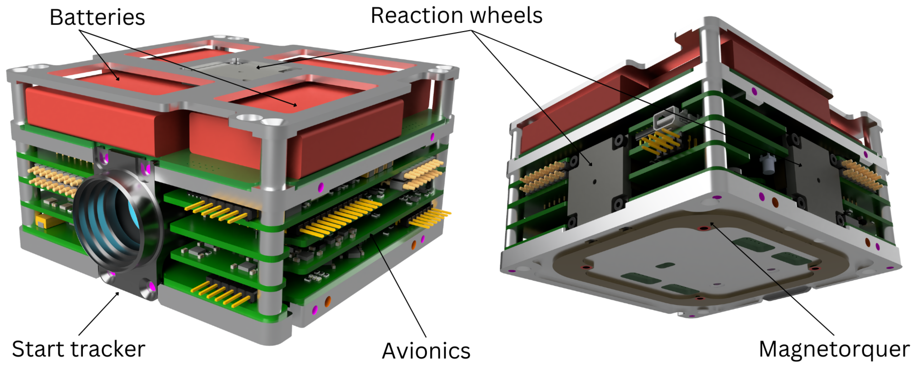
The avionics stack systems are the heart of the satellite. It consists of the onboard computer (OBC) system for task scheduling, data logging, and storage; the electrical power system (EPS) for energy storage and distribution; the communication system (COM) for telemetry and remote commands; the star tracker (ST); and the attitude and orbit control system (AOCS). The aforementioned systems are integrated into a 96 × 96 × 60 mm 3 volume (see Figure 8 and Figure 9). Each system is located on a different PCB and is implemented to use the allocated space in the satellite efficiently.
The electrical power system (EPS) is one of the most critical systems upon which the mission’s success depends greatly. The system ensures energy storage, voltage regulation, and power distribution on two boards.
The EPS battery management board controls and monitors the charging/discharging of the battery packs. The battery management PCB autonomously controls the charge and discharge currents depending on the voltage levels present. Temperature measurements of individual cells are performed to ensure the battery packs’ correct charge/discharge profile. The battery pack is configured in a 2s2p configuration and stores the energy generated by the solar arrays. Each series block of the pack consists of two commercial Panasonic 103,450 lithium-ion battery cells. Depending on the discharge state and temperature of the battery cells, this configuration ensures that the battery pack’s voltage ranges from ∼6.0 V to ∼8.4 V. Each series block is connected to the main power bus (MPB), an unregulated voltage rail supplied directly from the battery pack, and is responsible for the power path between the avionics stack and payloads.
The EPS main board is the core of the system. It incorporates hardware for an external Electrical Ground Support Equipment (EGSE) communication interface and uses a dedicated STMicroelectronics STM32L4 series microcontroller (MCU) to ensure power management functions. If required, it can override the autonomous control of the battery management board.
External analog-to-digital converters (ADCs) perform various voltage measurements for different current, voltage, and temperature level monitoring, which are stored on an external FRAM. Multiple avionics stack systems require a 3.3 V supply produced by two switching regulators. They operate in a hot-redundant configuration and convert floating MPB voltage with ∼90% conversion efficiency. A power switch for each avionics stack system provides power distribution functionality. The EPS MCU controls these switches and can sense over-current conditions that automatically trigger the off-state of the system.
Some satellite COTS systems cannot be powered from the MPB and require regulated voltage. Depending on the activity and current amplitude for a given voltage level, the MPB voltage is converted by switching or linear regulators. A switching regulator on the battery management PCB provides 5 V for the high-speed communication system (HSCOM). Two low-dropout regulators connected in parallel provide 5 V to the CGP payload.
The power budget of ESTCube-2 is visible in Table A2 and Table A3 in Appendix B.
The ESTCube-2 communication system (COM) communicates between the ground station (GS) and the satellite.
The system consists of two hot-redundant subsystems—primary communications (PCOM) and a backup subsystem called secondary communications (SCOM), housed on the same PCB. PCOM can receive and transmit signal on the radio amateur 70 cm band, and SCOM can receive on the radio amateur 2 m band and transmit on the 70 cm band, using AX.25-encapsulated data packets. SCOM serves the additional purpose of disabling the satellite’s transmission ability upon receiving an appropriate telecommand. This requirement comes from the international amateur radio union, as ESTCube-2 transmits on radio amateur frequencies [44].
The PCOM system is tuned at the radio amateur 70 cm band with a planned frequency of 435.8 MHz and 9600 to 19,200 bit/s variable data rate. Its processing unit is an STMicroelectronics STM32L4 series MCU, and RF connectivity is achieved with a Silicon Labs Si4463 transceiver.
SCOM is primarily used as a secondary receiver subsystem and uses a radio amateur 2 m band. The data processing unit is a Silicon Labs EZR32WG330 series MCU with a built-in RF transceiver module. For transmission, the subsystem can change its carrier frequency to the 70 cm band and use PCOM’s RF path to transmit the signal as a backup transmitter.
The link budgets of PCOM and SCOM are visible in Table A4, Table A5 and Table A6 in Appendix C.
The onboard computer (OBC) coordinates the operations of all systems and payloads and runs the AOCS algorithms using an STM32F7 series MCU. The MCU features 512 kB of static random-access memory (SRAM) and 2 MB flash memory for housekeeping and telemetry data storage.
The system can monitor the spacecraft’s overall health, mitigate identified failure scenarios, schedule telecommands for execution at a specific date and time, collect housekeeping and experiment data from payloads and other systems, perform data compression, and store the data in its onboard memory. At least two images of firmware are stored on the processor for redundancy. In addition, the system is capable of full firmware and delta updates, including an update roll-back mechanism for safety.
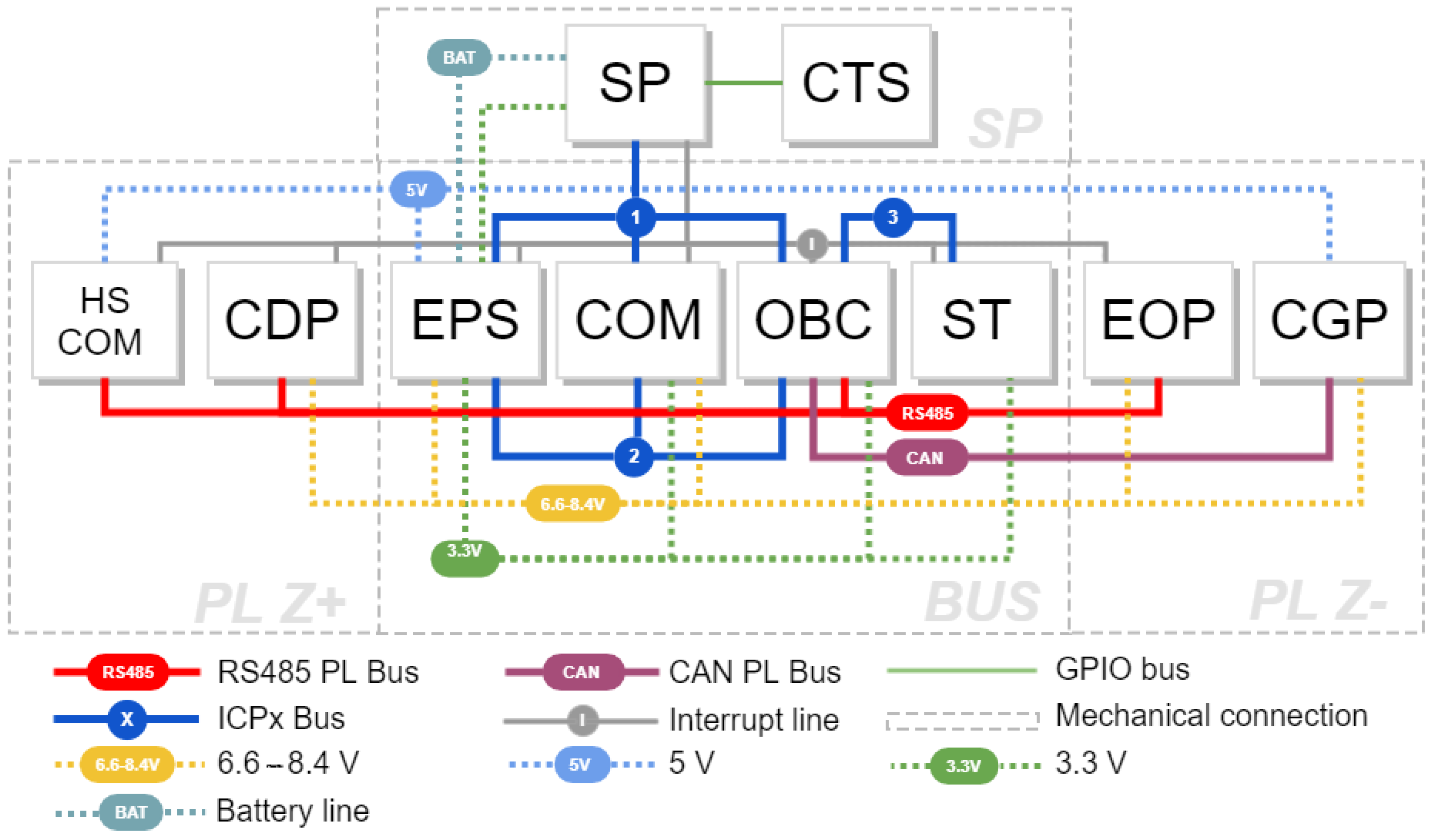
The OBC is central to all internal communications; the avionics stack is connected via three internal communication protocol (ICP) buses, and the payloads are connected via two CSP buses (see Figure 9).
Although the OBC has a real-time clock (RTC), it has no uninterruptible power supply. Since the EPS is the only system that has a battery-backed RTC, the OBC synchronizes time with the EPS. The OBC provides a time synchronization service for the payload modules.
The OBC board houses two redundant sets of microelectromechanical systems (MEMS) sensors: two magnetometers (LIS3MDL), two gyroscopes (BMG160), and an accelerometer (FXOS8700CQ) in each set for attitude determination purposes.
For the ESTCube-2 mission, the star tracker (ST) is an optional attitude determination system component. It was developed as part of the deep-space platform demonstration.
It consists of STMicroelectronics STM32L4-series-based MCU to gather different analog measurements from the PCB, configure the field-programmable gate array (FPGA), and enable communication with the complementary metal–oxide–semiconductor (CMOS) sensor.
An Altera Cyclone IV-based FPGA device processes the image, extracts the star location information, compares it to a database of known stars, and extracts the valuable attitude information. A 1/2.5-inch ON Semiconductor MT9P031 5 Mp monochrome CMOS image sensor and a high-resolution imaging lens with a 16 mm focal length and F/1.2 aperture are used to obtain images of the stars. Combining the sensor and optics yields a 21.5 × 15.7 field of view.
The image sensor and FPGA require specific voltage levels. Therefore, the voltage conversion is conducted locally on the ST PCB with switching or low-dropout regulators, depending on the current levels and input/output voltage differences.

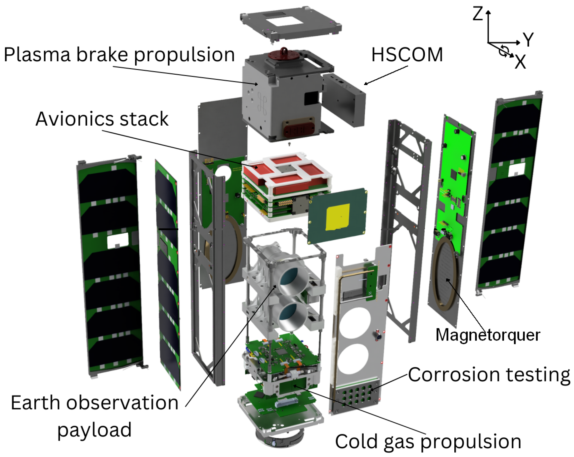
2.3.3. Side Panel Systems

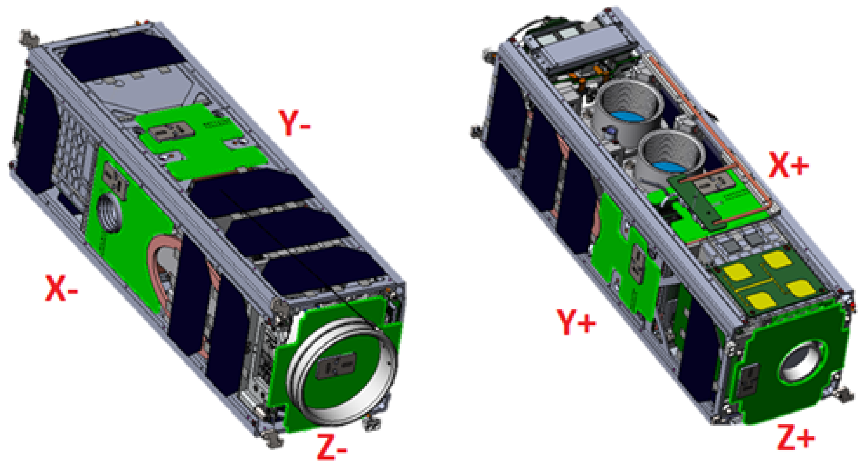
A side panel is a proxy system of the ESTCube-2 nanosatellite, and there is a different configuration on each of the six sides of the satellite (see 
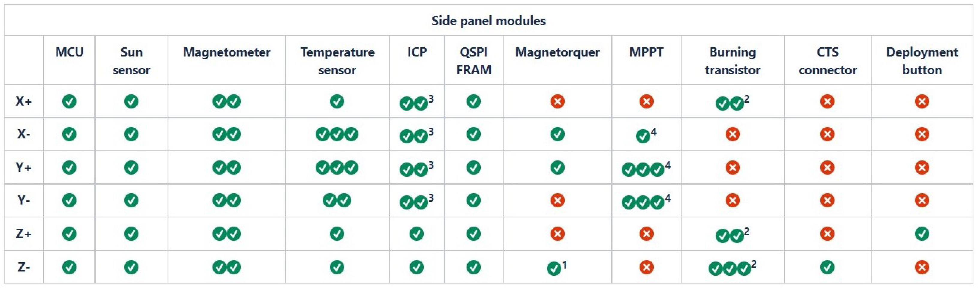
Figure 10). Each SP has a different functional block configuration depending on the necessary electronics hardware on each satellite’s side (see Figure 11).
The following are located on each SP system: STMicroelectronics STM32L4 series MCU, SS, magnetometer, one or more temperature sensors, FRAM memory, and ICP electronics.
On three PCBs are custom maximum power point tracker (MPPT) solutions for energy harvesting, capable of fast power point tracking during the satellite spin-up to deploy the IPB tether.
Driver electronics for three magnetorquers are located on those SPs closest to the actuators (except the bottom Z-axis side, see footnote 1 of Figure 11).
Approximately in the middle of every side of the satellite, there is a two-axis Sun sensor. The Sun sensors have been developed in-house and are an evolution of the similar analog sensors used on ESTCube-1 [26].
A single magnetometer on each of the SPs is used for better characterization of the residual magnetic field of the satellite and better-averaged measurement of the external magnetic field.

2.3.4. Attitude and Orbit Control System (AOCS)

On the ESTCube-2 satellite, the AOCS is a virtual system. Its components are housed on the OBC PCB or are integrated within the SPs. The AOCS system can be separated into three different major functional blocks, which work in tandem to fulfill the set mission requirements.
Mission requirements enforced the inclusion of an ST system (described in Section 2.3.2) and a CGP actuator (described later in this Section). These components enable attitude determination and control functionality outside the Earth’s magnetic field, thus, establishing a platform capable of successfully conducting deep-space missions. Still, for the ESTCube-2, they provide the necessary backup options for a successful LEO mission.
The sensor group comprises five types of sensors (described in Section 2.3.2 and Section 2.3.3):
1.
Magnetometers
2.
Gyroscopes
3.
Accelerometers
4.
Sun sensors
5.
Star tracker
The available actuators for controlling the satellite are:
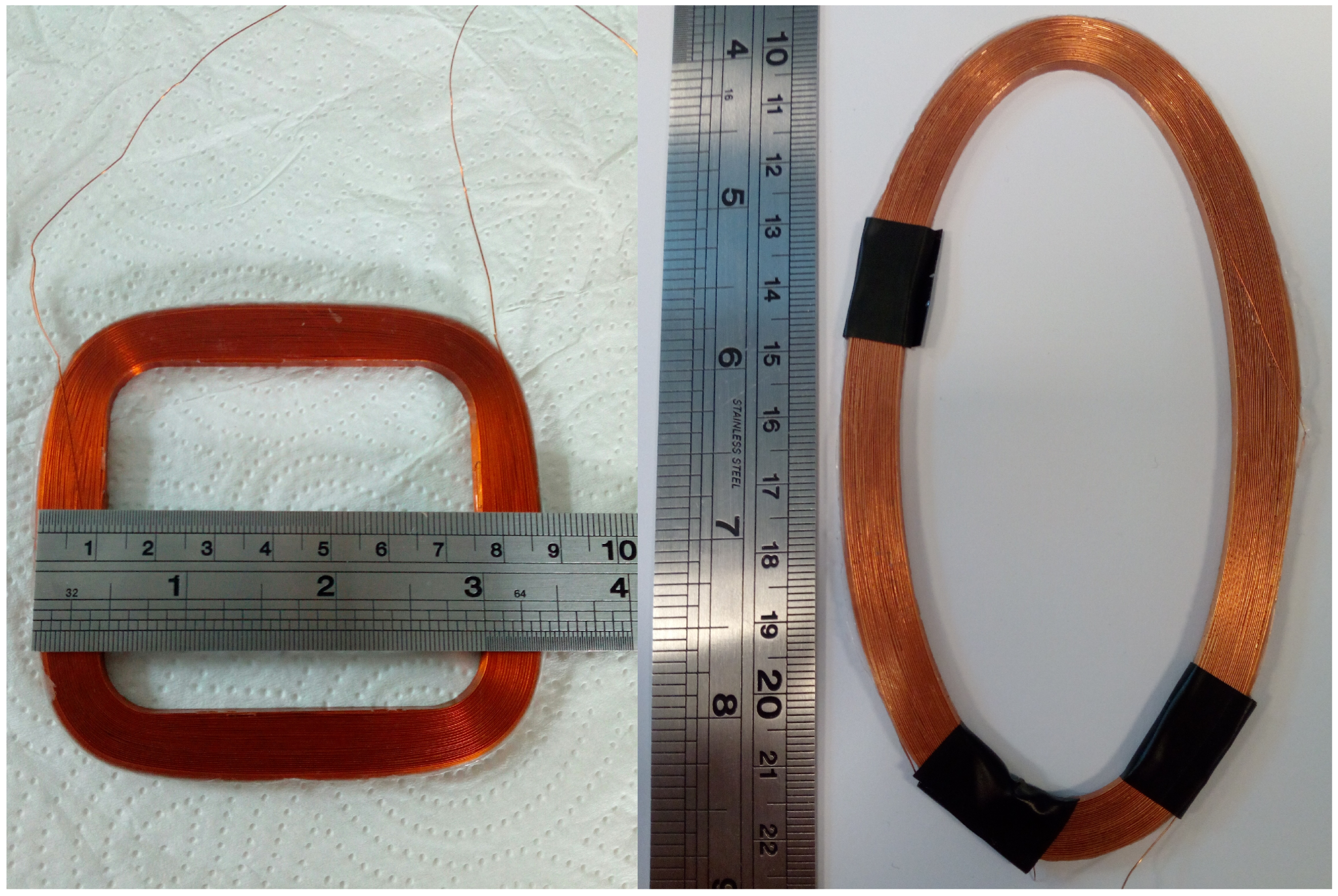
1.
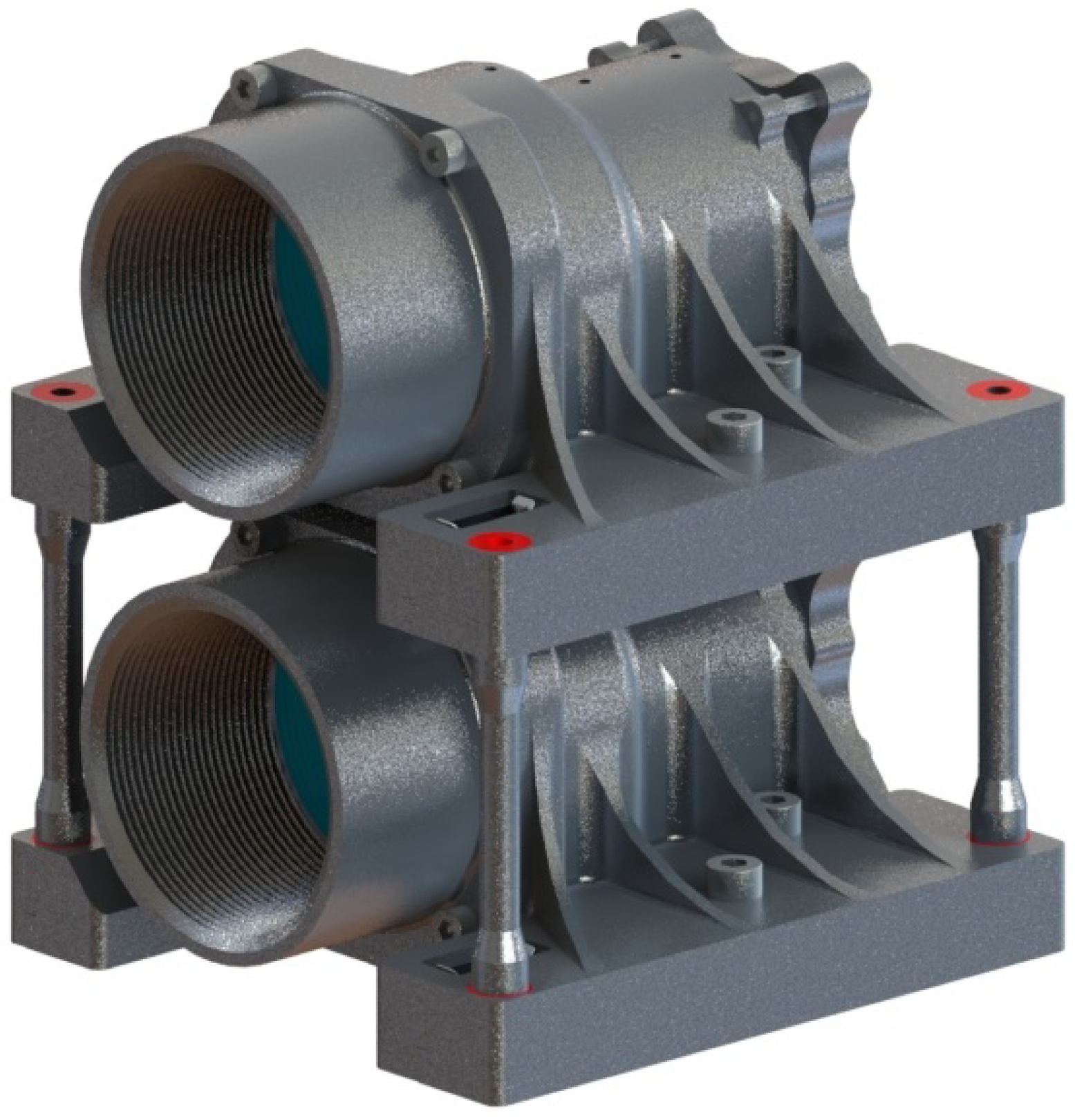
Three coreless magnetorquers with a magnetic moment of 0.45 A·m 2 made in-house (see Figure 12);
2.
Three Hyperion Technologies RW210 Series nanosatellite RWs. Dimensions: 25 × 25 × 15 mm3, Mass: 32 g, Momentum storage: 3.0 mNms;
3.
Three Wittenstein Cyber Motors CYBER2 nanosatellite RWs for redundancy. Dimensions: 20 × 20 × 20 mm3, Mass: 30 g, Momentum storage: 2.0 mNms;
4.
A GOMSpace NanoProp CGP3 CGP system.
Sensory data are interpreted in turn by various AOCS algorithms. The main AOCS algorithm is a type of unscented Kalman filter (UKF) capable of accounting for uncertainties arising from sensor measurements and temporal uncertainty of measurements taken.
The main requirement of the ESTCube-2 mission is to demonstrate the capability of executing each important maneuver, utilizing only the sensors and actuators available for deep-space missions.
There are four main maneuvers that the satellite must be able to execute for the mission to succeed:
  • Detumbling of the satellite to increase the reliability of communications between it and the ground station;
  • Satellite pointing for Earth observation camera operations and high-speed data downlink;
  • RW unloading/desaturating for continuous operations;
  • Satellite spin-up for IPB experiment tether deployment.
Detumbling operations will be achieved by a B-dot algorithm using magnetorquers. However, a specialized slower “predicting regulator,” which only uses the cold–gas propulsion module, will be tested for future deep-space operations.
Satellite pointing maneuvers are conducted using RWs following a PD-regulator control law. As a backup, the satellite can point itself using magnetorquers that employ a special PD-regulator.
The RW unloading is to be handled by stopping them gradually while using the detumbling controllers, but RW unloading using the CGP system is necessary for technology demonstration only. During the ESTCube-2 mission RWs will be desaturated using the magnetorquers.
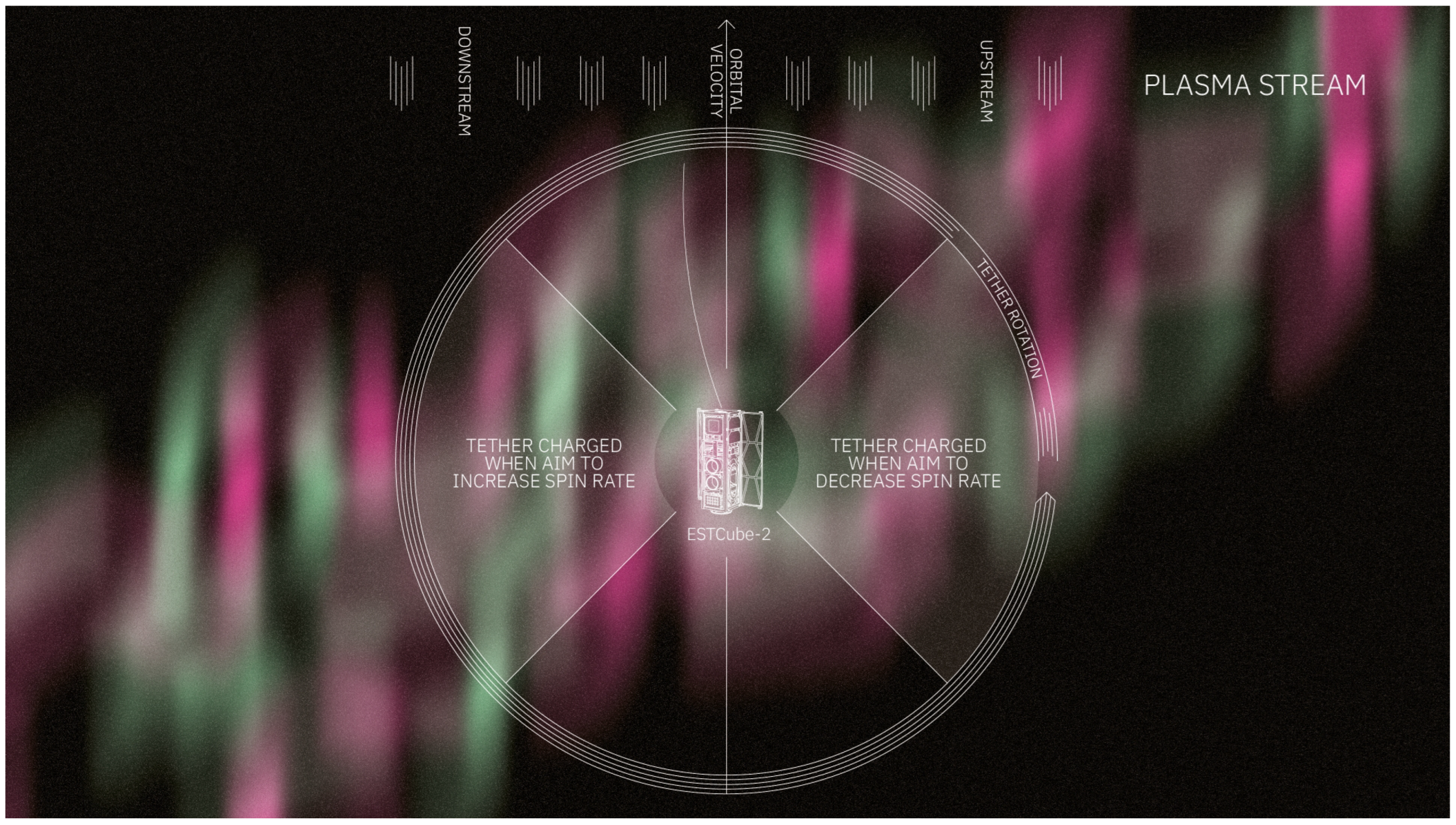
The spin-up of the satellite for the deployment of its main experiment—the ionospheric plasma brake—is handled by a double P-regulator, which uses cold–gas propulsion for technology demonstration, and magnetorquers are kept as a backup.
To increase the attitude and orbit determination precision externally, a radio satellite ranging experiment will be carried out, which aims to achieve the positioning of the satellite an order of magnitude more accurate than the two-line element set (TLE) using multiple collaborating ground stations and their respective locations.

2.3.5. Software Architecture

The software that enables the satellite to perform its scientific mission is developed alongside hardware and embedded software development.
During the development of ESTCube-1, it became clear that working with the STM hardware abstraction layer (HAL) created more problems than it solved, as described in [18]. A custom HAL was created by the team called ECHAL. ECHAL supports STM32 MCUs from F7, L4, and H7 families, making the software functions above this layer portable between them. The memory footprint of ECHAL is far smaller than STM HAL, and it fits into a bootloader.
Currently, the algorithm development is ongoing. The aim is to use the bootloader to deploy the final software onto the satellite after the launch. Before the launch, the main focus is sensor validation software. It focuses on the preprocessing of the sensor data and the relevant drivers that enable taking measurements from the sensors. As the satellite’s payload requires advanced attitude determination and control, many algorithms are under development to enable a successful mission.
The main focus on algorithm development has been on a robust Unscented Kalman Filter (UKF), satellite attitude and orbit control methods, and the ST algorithms. These algorithms are developed in a simulation environment and with more computing than is available on the satellite. Although this helps validate the algorithms, porting for use with ECHAL and optimizing them for use in orbit is still necessary. This will be finalized after receiving the first measurements from space and testing the algorithms using the sensor logs.
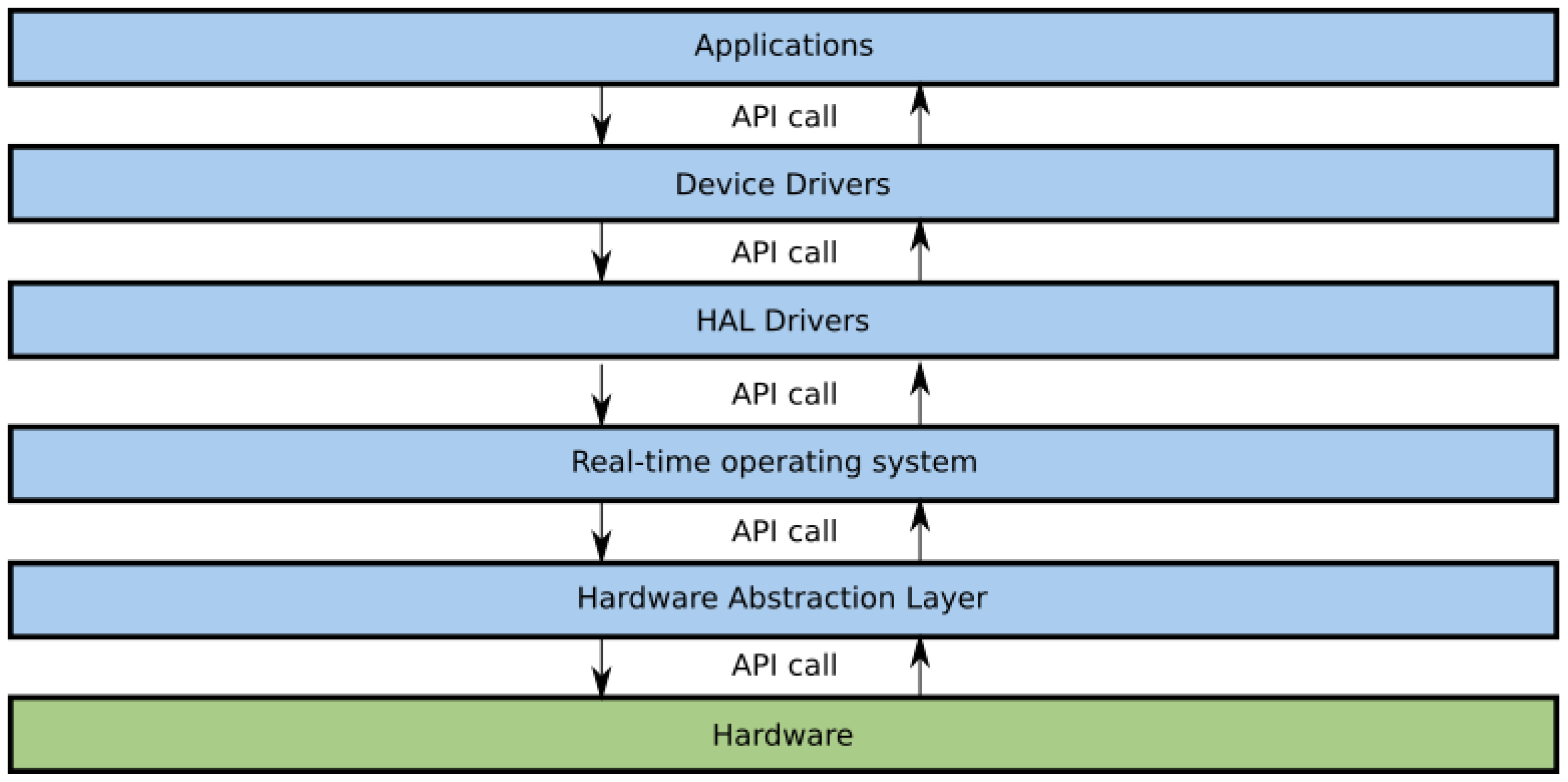
The firmware on all the satellite’s avionics stack systems is separated into logical layers, as summarized in Figure 13.
The ICP is used for the avionics stack system’s internal communication. A detailed description of this can be found in [18].

2.3.6. COTS Subsystems

Despite the mission requirements to create a deep-space platform in-house, two commercial systems have been acquired. They will assist in the payload experiments.
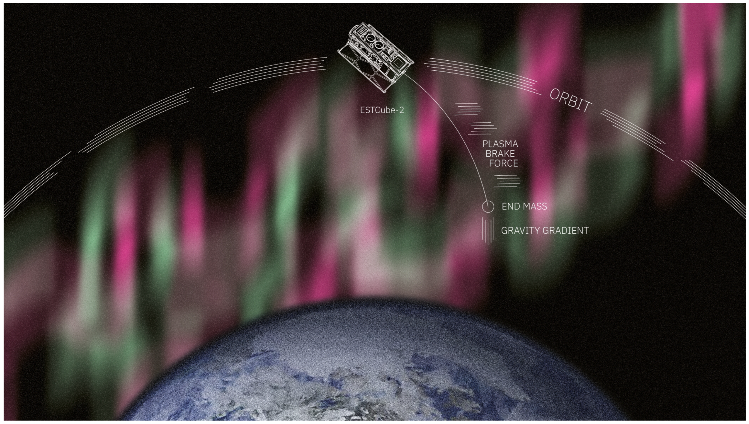
The GOMSpace NanoProp CGP3 cold–gas propulsion (CGP) system is used for the IPB tether deployment and maintenance. While it is possible to deploy the tether without additional propulsion in LEO, it will be required for E-sail deployment in deep space; therefore, for testing purposes, it will be used in LEO as well.
Compressed butane gas is used as the propellant. At operational conditions, the system would generate 1 mN thrust, and two nozzles at total capacity can run continuously for ten orbits (15 hours).
The system will be used only to desaturate the RWs, because of its suboptimal design (see Section 3.3).
A high-speed communications system (HSCOM) is required to download the spectral images made by the EOP. An S-band high-speed communications system HiSPiCO from IQ Spacecom is capable of up to 1 Mbps downlink speed. As our partner, who planned to use their high-speed communications system on board ESTCube-2, failed to deliver the system, our team was forced to find an alternative [18]. The HiSPiCO module size has allowed us to integrate the system easily because its form factor is not based on the CubeSat standard, and its dimensions fit into the envelope of the planned communications system. The system’s compact dimensions have allowed it to be located near the S-band patch antenna.
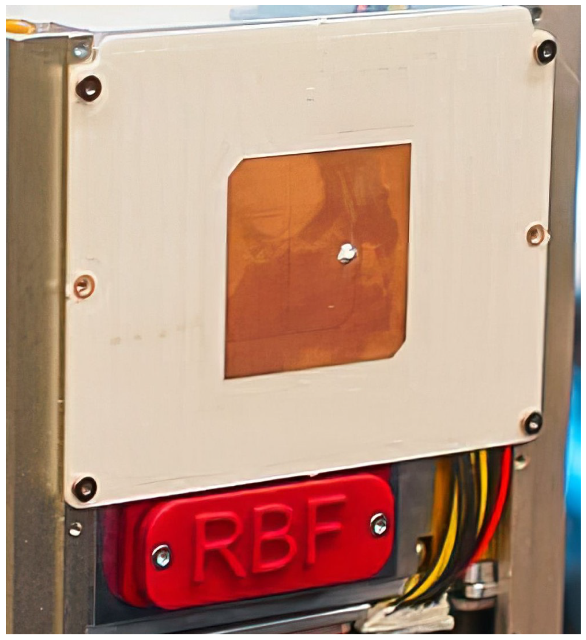
Even though most of the system is a COTS product, the S-band antenna was developed and tested in-house (see Figure 14). The antenna’s size was limited by the dimensions of the side of the satellite and the PB electron gun opening (see Figure 14’s RBF lid). The antenna is a circularly polarized patch-type antenna whose resonant frequency is 2.4 GHz. It has an ∼8 dBi gain, and its half-power beam width is ∼70 .
The link budget of the HSCOM is visible in Table A7 in Appendix C.

3. Satellite Development Lessons

Building a satellite requires intelligent decisions during the initial stages of the project. The management team challenged the idea of adherence to a CubeSat standard because, in a long-term vision of reaching capabilities for the MAT-type a mission [42], the CubeSat-type satellite is not required as the whole rocket can be used to launch tens or hundreds of spacecraft simultaneously using arbitrary design spacecraft. The management team learned that for technology demonstration purposes, the CubeSat standard would be the best design choice for the project. This helped us focus on the satellite design choices that must match the mission requirements and the team’s capabilities, which can change over time. In addition, existing and planned piggyback opportunities for CubeSat-based missions would allow the team to save funding.
In 2015, after surveying the available COTS satellite platforms, the team decided to take on a serious engineering challenge to develop the universal, compact, and integrated satellite bus platform in a two to three-year timeline. This decision was made because available COTS satellite solutions could not satisfy the mission requirements. The ambitious goal included developing a satellite structure with deployable panels, compact avionics electronics module, and side panels (see Section 2.3.1, Section 2.3.2 and Section 2.3.3) for interplanetary spacecraft prototype. Although we could not make a fully universal platform because payloads and procured COTS systems (see Section 2.3.6) required a custom interface development, designing the whole satellite from the ground up was a fantastic learning opportunity for every student who joined the project.

3.1. Hardware Development

The team decided to develop the whole satellite in-house. The decision to develop the whole satellite in-house makes it necessary to develop new skills in an academic environment if not already offered in the local study curricula.
One of the team’s toughest challenges was developing the satellite chassis structure. The team members were given an opportunity to learn engineering skills that were not available in their curricula because the University of Tartu lacks mechanical engineering curricula. To fix the lack of know-how, the recruitment efforts were focused on other local schools, helping us to create a collaboration between academic entities to allow for study credit point transfer.
Developing deployable structures on the satellite allowed the team to gain the know-how we can reuse in future missions for other purposes, like deployable antennas, deployable heat-sink, or deployable solar panels. A naive approach and lack of know-how of complicated deployable structure design resulted in slow initial development. The team discovered design problems after manufacturing the first satellite chassis and deployable panel structures. As a result, we found plenty of design problems leading to many last-minute redesigns and sub-optimal fixes.
For electronics hardware design, we found that the rapid iterative development approach helped us accelerate development and find the optimal solution in the shortest time. While developing various system electronics prototypes, the team spend a lot of time trying to make each prototype as good as possible. To avoid wasting money on manufacturing faulty electronics boards, many internal schematics and board reviews were performed, which delayed the progress of electronics development. This led to a lack of actual hardware for software development and tests. Late software tests revealed many hardware issues kept in design for a long time. Due to improper testing procedures or lost documentation of the testing results, the team could fix the hardware problems only by ordering new prototype boards.
The previously mentioned problems with mechanics and electronics prototype development stemmed from the team’s choice to order parts and electronics boards using local manufacturing capabilities. The local manufacturer’s expensive services made the team reluctant to use a rapid-prototyping approach. It stemmed from concern about using initial funding too quickly. One of the solutions could be for the academic institutions to invest in prototyping infrastructure, and if performed correctly, could have a return on investment already during the project. Our team solved this problem by finding other funding sources for the project and receiving manufacturing services from abroad to reduce the manufacturing costs per iteration of an electronics prototype or a structural part.
In 2015, the team chose a dual MCU architecture—STMicroelectronics STM32F7 series for high-performance tasks and Texas Instruments MSP430FR series for low-power and low-performance needs. The initial software was developed for STM32F7 MCU. When attempting to port the existing software to MSP430FR MCU, it revealed that our software architecture was too demanding. This required stopping the development of electronic hardware and software for systems using MSP430FR MCUs. For these systems, we decided to switch to STMicroelectronics STM32L4 series MCUs with significantly better performance with similar power consumption. Our embedded software team was used to develop software for STM32F7 MCUs, which made us believe that using the same development approach on a similar type MCU would be more efficient.

3.2. Software Development

We suggest assessing early in the project if the team shall create a new software suite instead of risking the software redesign at mid-development. In our case, at the beginning of the project, we decided to create our hardware abstraction layer (HAL), because the available HAL of the manufacturers was not deemed efficient.
When the ESTCube-2 project started, the core team members were convinced we needed to develop a HAL called ECHAL. It stemmed from the software development problems mentioned by Dalbins et al. [18]. At the beginning of the ESTCube-2 project, the ECHAL development was deemed necessary because STM HAL did not meet our firmware development requirements. It was unclear if ST Microelectronics would improve its software suite and what the timeline would be for it. The goal of our team was to develop a functional and well-thought-out HAL that would be lightweight on memory, have proper abstraction, and make good use of the general-purpose input/output (GPIO) definitions. This led to an opportunity for the students to get a chance to understand how multiple-layer firmware development is performed. Nevertheless, having our own HAL created high entry requirements for new members, and it became more complex as more of it was developed. Currently, there is not enough time to polish everything in ECHAL. As a result, the team has to finish a stable version of ECHAL, properly document it and publish it, which we plan to do under an open-source license.

3.3. Payload Integration

Proper interface documentation is mandatory in multi-partner collaborations as soon as possible and must be managed and reviewed for the project’s duration. As the ESTCube team had worked together with payload providers since the beginning of the project, we saw that most complications came from the bad interface specifications.
Even though the payload interface requirements were agreed upon at the beginning of the project, none of the payload teams could deliver everything as initially planned. As we did not review the status of payload interface readiness, this led to problems during the final stages of payload integration. To fix many payload problems, we had to outsource our existing developers to other payload teams. Our team developed parts of the payloads, software, and hardware, reducing our development capabilities temporalily.
Due to unforeseen funding problems, the initial high-speed communications system payload was dropped late in the development process of the satellite. We solved this by finding a COTS replacement solution and procuring it using reserved funding.
The CGP system supplier could procure a suboptimal system for the ESTCube-2 mission because we could not afford a custom configuration development quoted by the manufacturer. Due to this, the team decided to use the CGP system only for the ESTCube-2 RWs desaturation, which will be used to spin up the satellite to deploy the IPB tether using centrifugal force as the nozzles of the CGP system face in the bottom Z-axis direction (see Figure 7). This is a suboptimal solution as this cold–gas propulsion system has been designed for LEO satellite deorbiting rather than attitude control. As the system is not mission-critical, we decided to keep using this system, as finding a different one would require a major satellite redesign. The simulations made by the AOCS team show that the spin-up of the satellite is possible in this way [19,20,45,46].For an optimal solution, nozzles pointing in the Y-axis direction could be used for both RW desaturation and satellite spin-up (see Figure 7).

4. Management Lessons

4.1. Fundraising

Fundraising is the lifeline of every development project. We found that finding the right people to optimize and maximize the flow of funds has been a key factor of the project since its beginning.
Receiving early money is good, which showed that securing key people early is as important as developing the satellite. We were talented enough to receive a donation. It gave us a lot of autonomy in iterative developments to buy the first components in integration attempts. Moreover, we made a tax-exempt legal structure convenient for dealing with all vendors. The initial budget was also used for salaries and complemented by other sources supporting students. In the ideal case, the initial funds should be enough to secure the salaries of the project manager and the systems engineer until a prototype can be achieved. In our case, this was the intent, but the first prototype took more time than anticipated.
The team participated in a local crowdfunding campaign hosted by the Hooandja platform. This attempt educated the team on strategical planning of such activity to yield the highest amount of funding for ESTCube-2 development [30].
Taking part in business-orientated gatherings, like sTARTUp Day from Enterprise Estonia, helped the team to procure funding from investors orientated toward technology development. This gave an opportunity for team members to be exposed to a start-up environment, create a start-up company, and propose a product development plan.

4.2. Procurement of COTS

Procurement is always critical, although the NewSpace vendors make it appear more accessible. Adding geopolitical events, like the Covid-19 pandemic, will turn this task into a high-risk activity in the project that must be dealt with accordingly.
Acquiring COTS early in the project is vital as the lead time and the tests may last much longer than expected. The delivery dates and delays are different for every company, and that is essential to be followed up rigorously by the project manager. Although the vendors may be known by word-of-mouth reputation, managers should not trust them to provide an adequate system and must be strict with the manufacturer in case of subpar system delivery.
Payment often needs to be made upfront, which reduces the customer’s leverage. Usually, it is complicated to negotiate any penalties, but our team was negotiating discounts in case the manufacturer failed to deliver or created considerable delays. It is essential to consider that all deliveries will not occur on time, and schedule margins shall always be planned.
If the hardware manufacturer provides insufficient documentation of the system or its functionality, it is hard to detect this until tests have started. Therefore, in addition to the schedule margins, we recommend assigning people to test the procured parts as soon as they are delivered.
We experienced various issues in communication with the COTS providers: for instance, the delivery of the reaction wheels was delayed by several months, and their mechanical quality (vibration, rotation speed) was not as specified, the requested nozzle orientation of the propulsion was not understood, a precision milled part was improperly manufactured. There are always communication issues: minutes of meetings at the order and pre-delivery milestones are required and must be signed by both parties to avoid excuses of miscommunication.

4.3. People

In a student project, we attracted plenty of new members, which showed that keeping the project’s stakes and information up-to-date is crucial for the big-picture development direction. This is a demanding activity that has to be an essential part of the project.
We tried to integrate new members into a project team using a kind of “welcome package”, but we faced difficulty in keeping it up-to-date in the long run. In ESTCube-2, we prepared an introduction document, “ESTCuber guidebook”, with the purpose and goals of the project, the expected design, the schedule, the key people, and some programmatic aspects. After only two years, the document became outdated, but updating it was not deemed to be a priority. As a result, the document could not be used anymore, and the arriving students did not often understand the long-term and short-term project stakes. Hence, the core team had to spend more time introducing the current stakes. A possible solution would be to include a contribution to updating the welcome package in the students’ tasks and consider this contribution as part of their evaluation to receive their academic credits. Sometimes additional training is also needed for the newcomers. Updating training documentation and its setup shall also be part of the student deliverable for the project. This approach is likely more efficient than expecting the core team to update the necessary material.
A well-known concern with a student project is member turnover, which can also be an opportunity. The initial core team of ESTCube-2 came from the ESTCube-1 project and was highly motivated. In a long-term project, the core team has to be continuously renewed, and the influx of students is the natural source.
As ESTCube-2 development took longer than expected, the core team decreased to a minimum. To solve this, we decided to actively approach our team members to identify their motivations (acquiring skills or just gaining credits) to encourage them to take more responsibilities in the project (e.g., supervision, development plan), which provided the project with new momentum.
Like all projects in the same period, ESTCube-2 faced the COVID-19 pandemic, and we had to work remotely. We anticipated a substantial decrease in productivity before the 2020 summer, but we expected it to increase again during the summer when most of the development takes place. Unfortunately, the prolonged confinement meant the students were highly isolated and could not motivate themselves during this period. In addition, the coordination with remote meetings allowed many minor issues to stay unsolved from one meeting to the next, where a traditional co-located work could have solved such issues almost instantly. Remote work also does not help to share a broader view of other members’ tasks, like regular collective progress reports and informal discussions in an integrated team. Tools for cooperative work were adapted without recovering up-to-satisfactory efficiency until the end of the pandemic confinements.

4.4. Documentation during the Development

Using a simplified documentation architecture for the CubeSat project is smart and should be taken from existing standards; nevertheless, the documentation remains a pillar for a successful project. The ESTCube-2 team decided to have simplified and minimalist documentation to save time for the development of the satellite. We noticed that by the end of the project, documentation had become scattered and without a standard structure, even leading to duplicated information.
The general hope of CubeSats has been to simplify the projects, including their documentation. However, teams should not save time and money on documentation. Moreover, a “documentation system” must be carefully set up and maintained for the project’s entire duration.
As ESTCube-2 was built on the heritage of ESTCube-1, it was expected that the project would last only two to three years and could be kept simple. Moreover, assuming a short duration, written short-format documentation was deemed better. As the ESTCube-2 needed to be developed from the ground up, we could not reuse most of the ESTCube-1 design without additional work. This eventually led to the project needing more development time. As the core team members started to leave, the lack of documentation became a concern because most design choices stayed in the heads of leaving members. In a longer project, the traditional milestones of space mission developments in phases 0/A, B, C, and D appear well-adapted and should be taken as a management template for the nanosatellite developments. Such a management technique includes reviews at each milestone to address design issues promptly and avoid late re-design, fixes, and extra tests. We think such a project needs a “board of mentors” to review the development at every milestone.
Like the software development industry, the team adapted modern cooperative development tools (Confluence, JIRA, Google Drive, Discord). Still, it did not yield the expected results, and pressure to use these tools might have even slowed development in some disciplines, like, electronics and mechanics. First, electronics and mechanical hardware design cannot be as rapidly iterated as software projects. Second, the high turnover of students and their part-time availability in the project make them reluctant to learn and use new tools from the industry. As a result, the documentation structure on a shared cloud became scattered between multiple environments, making sharing work and ideas more complicated and previously made decisions lost. At last, we think that in such a project, the project manager should be responsible for the structure, the maintenance, and the delivery of writing and reading permissions to the shared documentation space. This person must have a clear understanding of the project’s stakes and milestones and some autonomy to organize the repository of the reference design and decisions.
The industry does not want to change the established development processes due to frequent outsourcing, requiring adherence to well-known standards. Companies told us that our students should become familiar with standards, like ECSS, as it is used in the space field. Students must experience that proper documentation is a collection of complete documents. A good compromise must be found between the documentation conducted in the industry and the student project; otherwise, their contribution can be lost. Eventually, comprehensive documentation by predecessors makes integrating new team members much more manageable, as discussed in Section 4.3. If the documentation shows the value of the project, it becomes an asset when we need to show the work status and when we need to communicate our work to partners or the rocket launch provider.

5. Leadership Lessons

A student satellite project is a place for the team members to grow. Nobody is born a leader, but good leadership is needed. Eventually, we could identify leadership characteristics to develop a project like ours.
The ESTCube-2 project became complex as a student project that needed to create its own identity, which was a challenge after the success of the ESTCube-1. The ESTCube-1 was the first Estonian satellite. It was considered a success by the nation and by the public. From a technical point of view, the satellite worked as expected, but the payload failed. In this context, ESTCube-2 could not simply be another ESTCube-1. As the objective of ESTCube-2 was new and its size grew three times, the core team initiated the ESTCube-2 project with the expectation to re-design most of the satellite and to make it a new engineering challenge. The ESTCube-1 benefited from a promotional campaign and received strong political support as a solution to prepare the next generation of engineers in Estonia. Then, the ESTCube-2 was believed to receive similar support, and an Estonian Student Satellite Foundation was created to provide the project with a legal entity and to receive funds. The new technical challenges and partnerships increased the project’s complexity, hence the need for new resources. A successful fundraising campaign was only possible because of the leadership of the initial core team, and the first donation kick-started the project in 2016.
As we saw from the fundraising, leadership differs from project management and must come in addition. It means specific skills, and because key people left the project, the project management was progressively losing leadership skills. Without a leader present, endless discussions about the motivations of some parts of the design, a loss of focus on the real stakes, and confusion in the documentation references arose. This resulted in the dilution of responsibilities resulting in weak and rushed design decisions. When the Covid-19 pandemic arose, the leadership situation got worse. Eventually, finding launch funding was successful, and when the core team was granted this opportunity, it rebuilt its confidence and, therefore, its leadership.
The central stake of the project leaders is to “sell” the project. New core team members must be shown that there are more skills to gain than technical know-how, and the industry sector also typically expects more. The motivation must go beyond the study duties for the best of them. We saw that the industry could recognize the best students as highly experienced even before graduation.
From our team’s experience, we assess what leadership should mean in a technical project like ours. We could identify three central soft skills, and these skills have to benefit the team during a two to three-year period of time in everyone’s life:
  • Full-filling high-level technical tasks and management tasks. The legitimacy comes from a field of expertise that is strategic for the project. The confidence level in that field must allow quick and efficient solutions to save the leader’s availability.
  • Identifying potential conflicts and assisting in their solution. It can be based on technical aspects but can also come from interpersonal relationships.
  • Finding the next leaders. In the long run, the team has to be renewed. The initial leaders will eventually leave, and the project needs to be prepared for that. The following leaders were identified among the participating students who were willing to lead and take ownership of the tasks.

6. Conclusions

This paper describes the design and development process of the ESTCube-2 nanosatellite. The payload description, the mechanical structure of ESTCube-2, its compact avionics stack electronics, and the software development approach have been detailed. As of May 2023, the ESTCube-2 satellite has been completed, tested, and prepared for launch onboard the VEGA-C VV23 rocket.
The ESTCube-2 project has been fully developed and led by doctoral, master, and bachelor students, mainly from the University of Tartu. During the development of the satellite, the ESTCube team dealt with many technical, management, and leadership problems. The “learn-by-doing” has been the main slogan of the team since the beginning of the ESTCube-2 project. This paper outlined the main takeaways of the technical, management, and leadership lessons, which are useful for system engineers, project managers, and team leaders.
In hindsight, some but not all of the problems we faced could have been solved by a standardized approach to project development. Nevertheless, this helped the core team of students to receive accelerated career training where they had to learn and grow together with the project by making mistakes and finding the most optimal solutions in various disciplines.

Author Contributions

Conceptualization: J.D., H.E., E.I., P.J., P.T., B.S. and A.S.; funding acquisition: I.I., P.J., M.N., M.P., A.S., B.S., A.T. and H.T.; project administration: A.S., M.N. and H.T.; software: J.D., K.A., H.E., E.I., I.S. and H.T.; supervision: B.S., M.N. and A.S.; visualization: J.D., I.I., P.T. and A.S.; writing—original draft: J.D., H.E., P.J., J.K., M.M., B.S. and A.S.; and writing—review and editing: I.I., E.I., B.S., A.S. and P.T. All authors have read and agreed to the published version of the manuscript.

Funding

The Tartu Observatory, the University of Tartu, the European Regional Development Fund, and the expertise pole CENSUS of Paris Observatory at PSL University France supported the research and development for this article. The ESTCube-2 was developed using the laboratory facilities of Tartu Observatory and funded by the TT8 and KosEST projects. The contributions of Ahti Heinla, Priit Salumaa, and more than 500 crowdfunding backers are very much appreciated for funding the development of ESTCube-2 [30]. The Earth Observation payload camera development was partially funded by 28,000 EUR fundraised during the sTARTUp Day from Enterprise Estonia. The financial support for partial ESTCube-2 hardware development was received from Estonian gaming, fintech, and blockchain company Yolo Group. Captain Corrosion OÜ funded the development of the corrosion materials testing module, receiving additional funding from Enterprise Estonia Development Voucher (Project EU51950). The Laboratory of Thin Film Technology, Institute of Physics, University of Tartu, prepared the coatings for the corrosion testing module with the help of Estonian-Ministry-of-Education-and-Science-funded projects IUT2-24 and TK141. The European Union supports the satellite launch of LEO on board Arianespace’s Vega-C rocket in cooperation with the European Space Agency via the In-Orbit Demonstration and Validation (IOD/IOV) initiative.

Data Availability Statement

Not applicable.

Acknowledgments

The lead author would like to thank Kristiina Akulitš, Laima Anna Dalbiņa, Aditya Savio Paul, and Boris Segret for their invaluable personal and mental support during the development of this paper. The authors would like to thank volunteers and industry partners who have contributed to the development of the ESTCube-2.

Conflicts of Interest

The authors declare no personal or financial conflict of interest.

Abbreviations

The following abbreviations are used in this manuscript:
ADCAnalog-to-digital converter
AOCSAttitude and orbit control system
CDPCoulomb drag propulsion
COMCommunication system
CGPCold–gas propulsion
CMOSComplementary metal–oxide–semiconductor
COTSCommercial-off-the-shelf
CSPCubeSat space protocol
CTSCorrosion Testing in Space
EGSEElectrical Ground Support Equipment
EOPEarth observation payload
EPSElectrical power system
FPGAField-programmable gate array
FRAMFerroelectric random-access memory
GPIOGeneral purpose input/output
HALHardware abstraction layer
HSCOMHigh-speed communications
ICPInternal communication protocol
LEOLow-Earth orbit
MATMulti-asteroid touring
MCUMicrocontroller
MEMSMicroelectromechanical systems
MPBMain power bus
MPPTMaximum power point tracker
OBCOnboard computer
IPBIonospheric Plasma Brake
PCBPrinted circuit board
PCOMPrimary communication system
RTCReal-time clock
RWReaction wheel
SCOMSecondary communication system
SDRAMSynchronous dynamic random-access memory
SPSide panel
STStar tracker
TLETwo-line element set
UKFUnscented Kalman filter

Appendix A

Table A1. Mass budget of the ESTCube-2.
Satellite Item GroupGroup Mass, g
Avionics stack679
Sidepanel and outer PCBs266.4
Main structure874.5
Deployable panels700.03
Ionospheric Plasma Brake555
High-speed communications139
Corrosion Testing in Space46
Earth observation payloads1170
Cold–gas propulsion350
Total4779.93
Total + 10%5257.92

Appendix B

Table A2. Power budget of the ESTCube-2 avionics stack.
SubsystemVoltage, VEstimated Consumption, mWMode
EPS3.3260MCU operation with peripherals
COM3.3400Transmit
MPB3000
3.3130Receive
MPB650
OBC3.3560MCU operation with peripherals
75AOCS Sensors
STMPB4370Image Acquisition
2822Image Processing
SP3.3401× SP active
1021× SP active + sun sensor
2501× ICP transmit
101× SP idle
AOCS3.324003× Reaction wheel maximum consumption
MPB40001× Magnetorquer maximum consumption
Table A3. Power budget of the ESTCube-2 payloads.
SubsystemVoltage, VEstimated Consumption, mWMode
CGP5200-
MPB6000-
HSCOM55000-
CRE3.3<300Active
EOP1MPB420Idle
1425Image Acquisition
EOP2MPB420Idle
1425Image Acquisition
E-SailMPB5500Wire burning (One time occurrence)
160Plasma brake mode
800E-sail mode

Appendix C

Table A4. Link budget of ESTCube-2 communications link for primary COM downlink. Frequency band 430–440 MHz.
ParameterSatellite TransmitterUnit
(9.6k bit/s)(38.6k bit/s)
Transmitter power30dBm
Transmitter losses1dB
Transmitter antenna gain3dBi
Antenna pointing error1dB
Equivalent isotropically radiated power (EIRP)31dBm
Elevation angle80503028050302
Losses
Distance (zenith 550 km)55869999324915586999932491km
Free space loss140.16142.12145.17153.16140.16142.12145.17153.16dB
Atmospheric loss1dB
Polarisation loss2dB
Total loss143.16145.12148.17156.16143.16145.12148.17156.16dB
Ground station receiver
Receiver antenna gain23dBi
Noise temperature1000K
Boltzmann constant−198.60dBm/K/Hz
Received power−89.16−91.12−94.17−102.16−89.16−91.12−94.17−102.16dBm
Data rate960038,600bit/s
SNR per bit (Eb/N0)39.6137.6634.6126.6233.5731.6128.5620.57dB
Required Eb/N0 for 2FSK modulation (G3RUH)18dB
Link budget reserve21.6119.6616.618.6215.5713.6110.562.57dB
Table A5. Link budget of ESTCube-2 communications link for primary COM uplink. Frequency band 430–440 MHz.
ParameterGround Station TransmitterUnit
(9.6k bit/s)
Transmitter power47dBm
Transmitter losses1dB
Transmitter antenna gain23dBi
Antenna pointing error1dB
Equivalent isotropically radiated power (EIRP)68dBm
Elevation angle8050302
Losses
Distance (zenith 550 km)5586999932491km
Free space loss140.16142.12145.17153.16dB
Atmospheric loss1dB
Polarisation loss2dB
Total loss143.16145.12148.17156.16dB
ParameterSatellite receiverUnit
(9.6k bit/s)
Receiver antenna gain3dBi
Noise temperature1500K
Boltzmann constant−198.60dBm/K/Hz
Received power−72.16−74.12−77.17−85.16dBm
Data rate9600bit/s
SNR per bit (Eb/N0)39.6137.6634.6126.62dB
Required Eb/N0 for 2FSK modulation (G3RUH)18dB
Link budget reserve21.6119.6616.618.62dB
Table A6. Link budget of ESTCube-2 communications link for secondary COM uplink. Frequency band 144–146 MHz.
ParameterGround Station TransmitterUnit
(1.2k bit/s)
Transmitter power47dBm
Transmitter losses1dB
Transmitter antenna gain18dBi
Antenna pointing error1dB
Equivalent isotropically radiated power (EIRP)63dBm
Elevation angle8050302
Losses
Distance (zenith 550 km)5586999932491km
Free space loss130.60132.56135.61143.60dB
Atmospheric loss1dB
Polarisation loss2dB
Total loss133.60135.56138.61146.60dB
Satellite receiver
Receiver antenna gain3dBi
Noise temperature1500K
Boltzmann constant−198.60dBm/K/Hz
Received power−67.60−69.56−72.61−80.60dBm
Data rate1200bit/s
SNR per bit (Eb/N0)68.4466.4863.4455.45dB
Required Eb/N0 for 2FSK modulation (G3RUH)18dB
Link budget reserve50.4448.4845.4437.45dB
Table A7. Link budget of ESTCube-2 communications link for high-speed COM downlink. Frequency band 2390–2450 MHz.
ParameterSatellite TransmitterUnit
(240k bit)(1M bit)
Transmitter power27dBm
Transmitter losses1dB
Transmitter antenna gain8dBi
Antenna pointing error1dB
Equivalent isotropically radiated power (EIRP)33dBm
Elevation angle80503028050302
Losses
Distance (zenith 550 km)55869999324915586999932491km
Free space loss155.00156.96160.01168.00155.00156.96160.01168.00dB
Atmospheric loss1dB
Polarisation loss2dB
Total loss158.00159.96163.01171.00158.00159.96163.01171.00dB
Ground station receiver
Receiver antenna gain34dBi
Noise temperature200K
Boltzmann constant−198.60dBm/K/Hz
Received power−91.00−92.96−96.01−104.00−91.00−92.96−96.01−104.00dBm
Data rate240,0001,000,000bit/s
SNR per bit (Eb/N0)30.7928.8325.7817.7924.5922.6319.5811.59dB
Required Eb/N011dB
Link budget reserve19.7917.8314.786.7913.5911.638.580.59dB

References

  1. CubeSat Design Specification. Revision 14.1. Available online: https://www.cubesat.org/cubesatinfo (accessed on 23 March 2023).
  2. State-of-the-Art Small Spacecraft Technology—Chapters 2 and 13: Complete Spacecraft Platforms. NASA, January 2023. Available online: https://www.nasa.gov/sites/default/files/atoms/files/2022_soa_full_0.pdf (accessed on 23 March 2023).
  3. Lawrence, A.; Rawls, M.L.; Jah, M.; Boley, A.; Di Vruno, F.; Garrington, S.; Kramer, M.; Lawler, S.; Lowenthal, J.; McDowell, J.; et al. The case for space environmentalism. Nat. Astron. 2022, 6, 428–435. [Google Scholar] [CrossRef]
  4. Inter-Agency Space Debris Coordination Committee. IADC Space Debris Mitigation Guidelines. IADC-02-01, Revision 2, March 2020. Available online: https://orbitaldebris.jsc.nasa.gov/library/iadc-space-debris-guidelines-revision-2.pdf (accessed on 23 March 2023).
  5. Federal Communications Commission. FCC Adopts New ‘5-Year Rule’ for Deorbiting Satellites to Address Growing Risk of Orbital Debris. Available online: https://docs.fcc.gov/public/attachments/DOC-387720A1.pdf (accessed on 23 March 2023).
  6. Janhunen, P. Simulation study of the plasma-brake effect. Ann. Geophys. 2014, 32, 1207–1216. [Google Scholar] [CrossRef]
  7. Iakubivskyi, I.; Janhunen, P.; Praks, J.; Allik, V.; Bussov, K.; Clayhills, B.; Dalbins, J.; Eenmäe, T.; Ehrpais, H.; Envall, J.; et al. Coulomb drag propulsion experiments of ESTCube-2 and FORESAIL-1. Acta Astronaut. 2019, 177, 771–783. [Google Scholar] [CrossRef]
  8. Slavinskis, A.; Pajusalu, M.; Kuuste, H.; Ilbis, E.; Eenmae, T.; Sunter, I.; Laizans, K.; Ehrpais, H.; Liias, P.; Kulu, E.; et al. ESTCube-1 in-orbit experience and lessons learned. IEEE Aerosp. Electron. Syst. Mag. 2015, 30, 12–22. [Google Scholar] [CrossRef]
  9. Mughal, M.R.; Praks, J.; Vainio, R.; Janhunen, P.; Envall, J.; Näsilä, A.; Oleynik, P.; Niemelä, P.; Nyman, S.; Slavinskis, A.; et al. Aalto-1, multi-payload CubeSat: In-orbit results and lessons learned. Acta Astronaut. 2021, 187, 557–568. [Google Scholar] [CrossRef]
  10. Palmroth, M.; Praks, J.; Vainio, R.; Janhunen, P.; Kilpua, E.K.J.; Afanasiev, A.; Ala-Lahti, M.; Alho, A.; Asikainen, T.; Asvestari, E.; et al. FORESAIL-1 CubeSat Mission to Measure Radiation Belt Losses and Demonstrate Deorbiting. J. Geophys. Res. Space Phys. 2019, 124, 5783–5799. [Google Scholar] [CrossRef]
  11. Klesh, A.; Baker, J.; Krajewski, J. MarCO: Flight Review and Lessons Learned. In Proceedings of the AIAA/USU Conference on Small Satellites, Year in Review 1, SSC19-III-04, Utah State University (USU), Logan, UT, USA, 3–8 August 2019; Available online: https://digitalcommons.usu.edu/smallsat/2019/all2019/276/ (accessed on 23 March 2023).
  12. Rivkin, A.S.; Cheng, A.F. Planetary defense with the Double Asteroid Redirection Test (DART) mission and prospects. Nat. Commun. 2023, 14, 1–3. [Google Scholar] [CrossRef]
  13. Thompson, M.R.; Rosen, M. Utilization and Validation of DSS-17 on the CAPSTONE Lunar Mission. In Proceedings of the 33rd AAS/AIAA Space Flight Mechanics Meeting, AAS 23-332, Austin, TX, USA, 14–19 January 2023. [Google Scholar]
  14. Liftoff! NASA’s Artemis I Mega Rocket Launches Orion to Moon. NASA Press Release 22-117. Available online: https://www.nasa.gov/press-release/liftoff-nasa-s-artemis-i-mega-rocket-launches-orion-to-moon (accessed on 23 March 2023).
  15. Lockheed Martin Space Twitter Mission Status Thread. Available online: https://twitter.com/LMSpace/status/1600926010752614405 (accessed on 4 April 2023).
  16. Mohon, L. NEA Scout Status Update. Available online: https://www.nasa.gov/centers/marshall/news/2022/nea-scout-status-update.html (accessed on 4 April 2023).
  17. Henry, J. JAXA’s Ultra Small Lander Omotenashi Fails to Receive Transmissions From Earth. Tech Times. Available online: https://www.techtimes.com/articles/283918/20221124/jaxas-ultra-small-lander-omotenashi-fails-receive-transmissions-earth.htm (accessed on 4 April 2023).
  18. Dalbins, J.; Allaje, K.; Iakubivskyi, I.; Kivastik, J.; Komarovskis, R.O.; Plans, M.; Sunter, I.; Teras, H.; Ehrpais, H.; Ilbis, E.; et al. ESTCube-2: The Experience of Developing a Highly Integrated CubeSat Platform. In Proceedings of the 2022 IEEE Aerospace Conference (AERO), Big Sky, MT, USA, 5–12 March 2022. [Google Scholar] [CrossRef]
  19. Ofodile, I.; Kutt, J.; Kivastik, J.; Nigol, M.K.; Parelo, A.; Ilbis, E.; Ehrpais, H.; Slavinskis, A. ESTCube-2 Attitude Determination and Control: Step Towards Interplanetary CubeSats. In Proceedings of the 2019 IEEE Aerospace Conference, Big Sky, MT, USA, 2–9 March 2019. [Google Scholar] [CrossRef]
  20. Ofodile, I.; Teras, H.; Slavinskis, A.; Anbarjafari, G. Towards an Integrated Fault Tolerant Control for ESTCube-2 Attitude Control System. In Proceedings of the 2022 IEEE Aerospace Conference (AERO), Big Sky, MT, USA, 5–12 March 2022. [Google Scholar] [CrossRef]
  21. Noorma, M.; Kulu, E.; Slavinskis, A.; Pajusalu, M.; Kvell, U.; Lätt, S. Estonian Student Satellite Program. In Proceedings of the 64th International Astronautical Congress, IAC-13.E1.3.5, Beijing, China, 23–27 September 2013. [Google Scholar]
  22. Olesk, A.; Noorma, M. The Engagement Activities of ESTCube-1: How Estonia Built and Fell in Love With a Tiny Satellite. In Space Science and Public Engagement; Chapter 9; Amy Paige Kaminski; Elsevier: Amsterdam, The Netherlans, 2021; pp. 169–183. [Google Scholar] [CrossRef]
  23. Lätt, S.; Slavinskis, A.; Ilbis, E.; Kvell, U.; Voormansik, K.; Kulu, E.; Pajusalu, M.; Kuuste, H.; Sünter, I.; Eenmäe, T.; et al. ESTCube-1 nanosatellite for electric solar wind sail in-orbit technology demonstration. Proc. Estonian Acad. Sci. 2014, 63, 200–209. [Google Scholar] [CrossRef]
  24. Ehrpais, H.; Kütt, J.; Sünter, I.; Kulu, E.; Slavinskis, A.; Noorma, M. Nanosatellite spin-up using magnetic actuators: ESTCube-1 flight results. Acta Astronaut. 2016, 128, 210–216. [Google Scholar] [CrossRef]
  25. Slavinskis, A.; Kvell, U.; Kulu, E.; Sünter, I.; Kuuste, H.; Lätt, S.; Voormansik, K.; Noorma, M. High spin rate magnetic controller for nanosatellites. Acta Astronaut. 2014, 95, 218–226. [Google Scholar] [CrossRef]
  26. Slavinskis, A.; Kulu, E.; Viru, J.; Valner, R.; Ehrpais, H.; Uiboupin, T.; Järve, M.; Soolo, E.; Envall, J.; Scheffler, T.; et al. Attitude determination and control for centrifugal tether deployment on the ESTCube-1 nanosatellite. Proc. Estonian Acad. Sci. 2014, 63, 242. [Google Scholar] [CrossRef]
  27. Slavinskis, A.; Ehrpais, H.; Kuuste, H.; Sünter, I.; Viru, J.; Kütt, J.; Kulu, E.; Noorma, M. Flight Results of ESTCube-1 Attitude Determination System. J. Aerosp. Eng. 2016, 29, 1–14. [Google Scholar] [CrossRef]
  28. Sünter, I.; Slavinskis, A.; Kvell, U.; Vahter, A.; Kuuste, H.; Noorma, M.; Kutt, J.; Vendt, R.; Tarbe, K.; Pajusalu, M.; et al. Firmware updating systems for nanosatellites. IEEE Aerosp. Electron. Syst. Mag. 2016, 31, 36–44. [Google Scholar] [CrossRef]
  29. Praks, J.; Mughal, M.R.; Vainio, R.; Janhunen, P.; Envall, J.; Oleynik, P.; Näsilä, A.; Leppinen, H.; Niemelä, P.; Slavinskis, A.; et al. Aalto-1, multi-payload CubeSat: Design, integration and launch. Acta Astronaut. 2021, 187, 370–383. [Google Scholar] [CrossRef]
  30. Kalnina, K.; Bussov, K.; Ehrpais, H.; Teppo, T.; Kask, S.-K.; Jauk, M.; Slavinskis, A.; Envall, J. Crowdfunding for satellite development: ESTCube-2 case. In Proceedings of the 2018 IEEE Aerospace Conference, Big Sky, MT, USA, 3–10 March 2018. [Google Scholar] [CrossRef]
  31. Iakubivskyi, I.; Mačiulis, L.; Janhunen, P.; Dalbins, J.; Noorma, M.; Slavinskis, A. Aspects of nanospacecraft design for main-belt sailing voyage. Adv. Space Res. 2020, 67, 2957–2980. [Google Scholar] [CrossRef]
  32. Janhunen, P. Electrostatic Plasma Brake for Deorbiting a Satellite. J. Propuls. Power 2010, 26, 370–372. [Google Scholar] [CrossRef]
  33. Slavinskis, A. Plasma Brake for Deorbiting in low Earth orbit. Space Travel Blog. Available online: https://space-travel.blog/plasma-brake-f9de377f2b21 (accessed on 4 April 2023).
  34. Connection to the Foresail-1 Science Satellite Is Lost—The Construction of a New Satellite Is Already Underway. Aalto University News. Available online: https://www.aalto.fi/en/news/connection-to-the-foresail-1-science-satellite-is-lost-the-construction-of-a-new-satellite-is (accessed on 4 April 2023).
  35. Sünter, I.; Kuuste, H.; Slavinskis, A.; Agu, A.; Ilbis, E.; Olentšenko, G.; Iakubivskyi, I.; Kütt, J.; Vendt, R.; Chopra, S.; et al. Design and testing of a dual-camera payload for ESEO. In Proceedings of the 67th International Astronautical Congress, B4.4.3.x31978, Guadalajara, Mexico, 26–30 September 2016; Available online: https://www.researchgate.net/publication/308053813 (accessed on 23 March 2023).
  36. Dalbins, J.; Ehrpais, H.; Ilbis, E.; Iakubivskyi, I.; Oro, E.; Eenmae, T.; Sünter, I.; Janhunen, P.; Envall, J.; Toivanen, P.; et al. ESTCube-2 mission analysis: Earth observation imager system. In Proceedings of the F27-3, General Assembly and Scientific Symposium and International Union of Radio Science, 32nd URSI GASS, Montreal, QC, Canada, 19–26 August 2017. [Google Scholar]
  37. Sentinel-2 User Handbook. Sentinel Online, ESA. Available online: https://sentinels.copernicus.eu/documents/247904/685211/Sentinel-2_User_Handbook (accessed on 23 March 2023).
  38. Laizans, K.; Sünter, I.; Zalite, K.; Kuuste, H.; Valgur, M.; Tarbe, K.; Allik, V.; Olentšenko, G.; Laes, P.; Lätt, S.; et al. Design of the fault tolerant command and data handling subsystem for ESTCube-1. Proc. Estonian Acad. Sci. 2014, 63, 222. [Google Scholar] [CrossRef]
  39. Captain Corrosion OÜ. Corrosion Monitoring System. Europe Patent EP20177638.2, 1 June 2020. [Google Scholar]
  40. Merisalu, M.; Aarik, L.; Kozlova, J.; Mändar, H.; Tarre, A.; Sammelselg, V. Effective corrosion protection of aluminum alloy AA2024-T3 with novel thin nanostructured oxide coating. Surf. Coatings Technol. 2021, 411, 126993. [Google Scholar] [CrossRef]
  41. Sammelselg, V.; Aarik, L.; Merisalu, M. Patent: Method of Preparing Corrosion Resistant Coatings. WO 2014102758 A1, 31 December 2012. European Patent EP 2 938 758 B1, the Application granted 16–11–2016; U.S. Patent 9,834,849 B2, the Application granted 05–12–2017; Japan Patent: JP 6336477 B2, the Application granted 06–06–2018. [Google Scholar]
  42. Slavinskis, A.; Janhunen, P.; Toivanen, P.; Muinonen, K.; Penttila, A.; Granvik, M.; Kohout, T.; Gritsevich, M.; Pajusalu, M.; Sunter, I.; et al. Nanospacecraft fleet for multi-asteroid touring with electric solar wind sails. In Proceedings of the 2018 IEEE Aerospace Conference, Big Sky, MT, USA, 3–10 March 2018. [Google Scholar]
  43. ISISpace CubeSat ISIPOD Deployer’s 3-Unit CubeSat Dimensions. ISISPACE CubeSat Supported Sizes. Available online: https://www.isispace.nl/wp-content/uploads/2015/12/ISIS.STS_.0.1.003-RevB-Sheet1-1-3U-CubeSat-Dimensions-A0.pdf (accessed on 15 May 2023).
  44. The International Amateur Radio Union. Controlling Space Station Transmitters. Available online: https://www.iaru.org/wp-content/uploads/2019/12/controllingsatellites_v27.pdf (accessed on 17 March 2023).
  45. Kvell, U.; Puusepp, M.; Kaminski, F.; Past, J.-E.; Palmer, K.; Grönland, T.-A.; Noorma, M. Nanosatellite orbit control using MEMS cold gas thrusters. Proc. Estonian Acad. Sci. 2014, 63, 279. [Google Scholar] [CrossRef]
  46. Ofodile, I.; Ofodile-Keku, N.; Jemitola, P.; Anbarjafari, G.; Slavinskis, A. Integrated Anti-Windup Fault-Tolerant Control Architecture for Optimized Satellite Attitude Stabilization. IEEE J. Miniaturization Air Space Syst. 2021, 2, 189–198. [Google Scholar] [CrossRef]
Figure 1. The Coulomb drag propulsion tether has a redundant structure, making it resistant to micrometeoroid and orbital debris impacts. The wire thickness is 50 μ m. A human hair is used for scale below.
Aerospace 10 00503 g001
Figure 2. Satellite spin rate change with the E-sail tether in the Earth’s ionosphere [33]. The tether is charged while moving downstream or upstream of ionospheric plasma to increase or decrease the satellite spin rate, respectively. The change in spin rate would be noticeable in one or a few orbits (depending on the deployed tether length). Artwork credit: Laila Kaasik, Rute Marta Jansone, and Anna Maskava.
Aerospace 10 00503 g002
Figure 3. Deorbiting with ionospheric plasma brake in the low-Earth orbit ionosphere [33]. As the satellite moves through the relatively stationary ionosphere, the charged tether creates a braking force to deorbit the satellite. Given the satellite’s orbital parameters, the plasma brake deorbiting effect would take weeks to months to be noticeable. Artwork credit: Laila Kaasik, Rute Marta Jansone, and Anna Maskava.
Aerospace 10 00503 g003
Figure 4. A render of the Ionospheric Plasma Brake module.
Aerospace 10 00503 g004
Figure 5. A render of the Earth Observation Payload camera modules.
Aerospace 10 00503 g005
Figure 6. The compact 65 × 41 mm 2 satellite module used for testing 15 materials in space, which consists of a printed circuit board (PCB) with coated materials and a cover plate with holes to expose tested materials to atomic oxygen in LEO.
Aerospace 10 00503 g006
Figure 7. Exploded view of the 3U satellite, which showcases the satellite and its systems’ arrangement. The attitude and orbit control system (AOCS) components are distributed throughout the satellite—in the avionics stack (see Figure 8), cold gas propulsion, magnetorquers on side panels of X− axis Y+ axis directions, and sensors on the six side panel PCBs.
Aerospace 10 00503 g007
Figure 8. A render of the satellite avionics stack electronics module. System names starting from the top: battery management printed circuit board (PCB) with batteries; electrical power system; communication system; onboard computer; star tracker. The AOCS components in the avionics stack—reaction wheels, star tracker, magnetorquer at the bottom of the stack, and sensors on the onboard computer (OBC) board.
Aerospace 10 00503 g008
Figure 9. The inter-system electrical and the data-connections architecture. SP: side panels, CTS: Corrosion Testing in Space, HSCOM: high-speed communications, CGP: Coulomb drag propulsion (Ionospheric Plasma Brake), EPS: electrical power system, COM: communications system, OBC: onboard computer, ST: star tracker, EOP: Earth observation payload, CGP: cold–gas propulsion.
Aerospace 10 00503 g009
Figure 10. Side panel locations and naming.
Aerospace 10 00503 g010
Figure 11. Side panel configuration table. 1. The bottom Z-axis side panel controls the magnetorquer. However, the coil driver components are physically on the ST PCB. 2. Resistor count for deployable structures. 3. Both internal communication protocol (ICP) buses for redundancy. 4. Additional maximum power point trackers (MPPT) for deployable side panels.
Aerospace 10 00503 g011
Figure 12. Two of three in-house developed coreless magnetorquers.
Aerospace 10 00503 g012
Figure 13. Subsystem software architecture.
Aerospace 10 00503 g013
Figure 14. In-house developed circularly polarized S-band patch antenna.
Aerospace 10 00503 g014
Disclaimer/Publisher’s Note: The statements, opinions and data contained in all publications are solely those of the individual author(s) and contributor(s) and not of MDPI and/or the editor(s). MDPI and/or the editor(s) disclaim responsibility for any injury to people or property resulting from any ideas, methods, instructions or products referred to in the content.

