Article

A Simulation Framework for Aircraft Take-Off Considering Ground Effect Aerodynamics in Conceptual Design

1
Department of Civil and Industrial Engineering, University of Pisa, Via Caruso 8, 56122 Pisa, Italy
2
Schindler Aufzüge AG, Corporate Research & Development, Zugerstrasse 13, 6030 Ebikon, Switzerland
*
Author to whom correspondence should be addressed.
Aerospace 2023, 10(5), 459; https://doi.org/10.3390/aerospace10050459
Submission received: 6 April 2023 / Revised: 5 May 2023 / Accepted: 12 May 2023 / Published: 15 May 2023
(This article belongs to the Special Issue Flight Dynamics, Control & Simulation)

Abstract

:
The development of novel aircraft concepts and propulsion technologies requires up-to-date physics-based methods and tools for conceptual aircraft design. In this context, a simulation model for the take-off manoeuvre is proposed in this article, to be employed in the conceptual design phase for aircraft whether of traditional or innovative configuration. The model is capable of evaluating the longitudinal dynamics, both translational and rotational, of the aircraft considered as a rigid body, and influenced by the aerodynamic effects introduced by the presence of the ground. The ground effect, indeed, induces variations in the aerodynamic forces depending on the distance and the attitude of the lifting surfaces from the ground, which may significantly influence the aeromechanical characteristics of the aircraft during the evolution of the take-off manoeuvre. The simulation model is based on the numerical solution of the equations of the dynamics of the rigid aircraft in the longitudinal plane and integrates a vortex lattice aerodynamic solver to evaluate the aerodynamic and aeromechanical characteristics of the aircraft considering the ground effect in each time-step. The proposed approach is configuration independent, as it can model the geometry, evaluate the aerodynamics, and simulate the dynamics of aircraft with any lifting architecture; furthermore, the simulation model is fast and flexible, making it effective for the conceptual phase of aircraft design. The paper proposes the description of the take-off manoeuvre of two aircraft with different airframes: one with a conventional tube-and-wing architecture and one with a box-wing lifting system. The results proposed highlight the potential of the simulation model to detect aeromechanic and dynamic differences during the development of the manoeuvre for different aircraft configurations, and to assess the significance of considering ground effect aerodynamics.

1. Introduction

1.1. Overview of the Research

Conceptual design plays a crucial role in the development of a transport aircraft; indeed, the choices made in this phase have a decisive impact on the subsequent advancement of the project, and errors and inconsistencies made in this stage can slow down or even compromise the development of a complex product such as a transport aircraft [1,2,3]. For this reason, the research and development of up-to-date methods and tools for conceptual aircraft design are always progressing [4,5,6,7,8].This is already of considerable importance when it comes to develop aircraft of traditional architecture, but it becomes of paramount significance when it involves developing innovative aircraft, which have novel features in terms of airframe, propulsion, and aeromechanics. At a time when transport aviation is mandatorily facing an ecological transition towards a new era of air mobility with minimal climate impact [9,10,11,12], the investigation of new aircraft configurations has become crucial. Extensive research in aircraft design is devoted to investigating new aircraft architectures that appear to be more efficient [13], such as box-wing [14,15,16], truss-braced wing [17,18], and blended-wing-body [19,20,21,22]. The integration of such architectures with new, less polluting propulsion models, such as electric [23,24,25,26], hybrid-electric [27,28,29,30], or hydrogen [31,32,33,34], is another core topic of aeronautical research. The development of rapid yet reliable models, techniques, and tools for conceptual design that are capable of assessing such innovative configurations is therefore of key relevance [35,36,37,38].
Unconventional configurations, new propulsion concepts and, in general, technical innovations that have never been introduced in the past, cannot, therefore, be subjected to the use of simplified methods based only on experience, databases, and empirical models, which are instead widely used to initialise the design of aircraft with traditional configurations. It is necessary to develop simple but reliable models that are based on the physics of the problems addressed during design, whether they are structural, aerodynamic, aeroelastic, propulsive or aeromechanical issues. The research proposed in this article is intended to represent an additional step in this context, by introducing a methodology to analyse the take-off manoeuvre of a generic aircraft to be employed in the conceptual phases of design, also for aircraft with innovative configurations. Specifically, in this work a simulative model of the take-off manoeuvre, useful for evaluating the performance of the aircraft and for determining the main correlations between these and the main design parameters, is presented. The developed simulative model is based on the equations of the dynamics of the rigid aircraft in the longitudinal plane and integrates a potential aerodynamic solver (namely, the Vortex Lattice Method) to evaluate the aerodynamic and aeromechanical characteristics of the aircraft considering the ground effect. The peculiarities of this model are to be found specifically in its ability to evaluate the longitudinal dynamics, both translational and rotational, of the aircraft considered as a rigid body, while assessing the aerodynamic performances affected by the presence of the ground. The ground effect, introduces variations in the aerodynamic forces depending on the distance and the attitude of the lifting surfaces from the runway; these modifications to the aerodynamic forces may have significant effects on the aeromechanical characteristics of the aircraft, and may influence the development of the take-off manoeuvre, in terms of trajectory, field length, stability, and kinematic parameters. These effects, which can affect the take-off dynamics for a tube-and-wing aircraft, can be even more influential for aircraft with non-conventional lifting architectures, with lifting surfaces of other shapes or arranged differently with respect to the ground. To address this instance, the model developed in this research is called configuration agnostic [39], as it is capable of modelling the geometry, assessing the aerodynamics, and simulating the dynamics, of aircraft with any lifting architecture. In this paper, to illustrate these aspects and show how different lifting architectures may have different aeromechanical characteristics in ground effect and during the take-off manoeuvre, two different test cases are introduced: an aircraft with a conventional tube-and-wing architecture and one with a box-wing lifting system. The developed simulation model is fast and flexible, proving to be effective for the conceptual phase of aircraft design.
The layout of this paper is organised as follows: in Section 1.2, a state-of-the-art analysis on simulative take-off models and their application to aeronautical design is proposed; their peculiarities and limitations are highlighted to emphasise the features introduced by the simulative model proposed in this research. Section 2 describes the mathematical model of flight dynamics and the simulation techniques used. Section 3 is dedicated to the description of the aerodynamic in ground effect and how this is assessed during the simulation of the manoeuvre; a comparison of the aerodynamic characteristics in ground effect between the tube-and-wing (TW) and the box-wing (BW) aircraft is also proposed, considering variations both in the distance from the ground and in the pitch attitude. Section 4 and Section 5 report, respectively, the results of the take-off simulations for the two configurations, together with a discussion of their aeromechanical features, and the optimisations process related to the search of the minimum required runway length. Finally, the main outcomes of this research are provided in Section 6.

1.2. State of the Art of Take-Off Simulation Methods

In this section, an overview of the literature methods to take the take-off performance in conceptual design into account is presented; a wide variety of models and tools are available in the literature, which can be classified into three main categories, namely empirical, analytical, and simulation-based methods. Empirical methods are basically built on historical data, their extrapolation, and their statistical utilization; correlation of data coming from operating aircraft or flight test are used to predict the take-off performance of a new aircraft; some examples can be found in Refs. [40,41,42]. These simple models provide fast assessments of take-off performance, proving to be very useful in the very early stages of aircraft sizing; however, they have several limitations, as their accuracy can be very weak, and the data are often only applicable for aircraft that are very similar to those used to build the databases and the related statistical extrapolations. Analytical methods provide simple and direct mathematical equations that describe the physical processes that occur during take-off; often, a number of assumption and hypotheses are imposed to the model to reach to closed form solution generally applicable to the considered problem. These equations are derived from a simplified representation of the equation of motion and can take into account the aerodynamics, propulsion, mechanics of the aircraft; analytical take-off performance models can be found in Refs. [43,44,45]. Although these methods are very simple and fast, so being suitable for conceptual aircraft design, they are useful mainly to identify trends between performance and macroscopic parameters, rather than providing indications on the actual behaviour of a specific configuration. This is particularly true when dealing with novel airframes or aircraft architectures. Finally, simulation-based methods are based on the use of numerical models applied to equations of motion to evaluate the physics of the take-off manoeuvre; these methods can be used to predict the aircraft’s kinematics as well as its aerodynamic and aeromechanic performance. Typically, simulation-based methods allow for the prediction of take-off performance of aircraft with different lifting and/or propulsive configurations; however, different degrees of accuracy can be provided by these models, ranging from a representation of the aircraft as a point mass to a complete 3D representation of the geometry and the flow field. As accuracy increases, there is a corresponding increase in the required computational cost, and this needs to be carefully considered in the conceptual design phase. Modelling and simulation of aircraft take-off has been an area of interest in the field of aeronautical engineering research, as evidenced by the numerous studies on the subject; the Ref. [46] presents the evaluation of aircraft take-off and landing performance, based on a 6-DOF simplified simulation model; the tool allows an assessment of take-off distances and reference speeds, as well as the study of failure cases, to evaluate the compliance with the certification requirements. In Ref. [47] is presented a preliminary idea of an algorithm to predict aircraft trajectories during take-off, which integrates radar measurements and wind evolution into the aircraft dynamic model, to decrease uncertainty on the position of the aircraft. Ref. [48] proposed the development of a simulation model for a small aircraft, which showed good agreement with their available flight test data. Ref. [49] studied the aerodynamic interference effects on aircraft take-off and landing, by extrapolating data from high-fidelity aerodynamic database. Ref. [50] proposes a framework to compare the take-off performance of small aircraft with two and three lifting surfaces respectively, focusing on the take-off distance as a figure of merit. Finally, Ref. [51] proposes a simulation process to assess the noise impact associated with a benchmark supersonic transport aircraft configuration during approach and departure. Although of high significance, the previous proposed methods are not generalizable for the utilization in conceptual aircraft design, as they rely on specific tuned datasets, or are developed for a specific case/condition, or are not capable to reproduce and assess generic aircraft configurations and their performance. In this regard, on the other hand, the research proposed in Ref. [52] provides interesting insights, as it describes a simulation model to assess the take-off performance of a generic transport aircraft within the conceptual design phase. The research proposed in Ref. [52] is very relevant, as the proposed approach enables the modelling, the simulation, and the analysis of the take-off manoeuvre of a generic aircraft configuration with adequate rigour in the dynamic model assumptions, providing accurate but fast assessments. This model needs the aircraft aerodynamic polar curves as input, or can be integrated into a wider design framework [53,54] to assess the aerodynamics; in any case, the aerodynamic performance take the ground effect into account with the very simplified relations proposed in Ref. [55]. Furthermore, the dynamic model is derived based on the assumption of point mass aircraft, thus neglecting take-off rotational dynamics evolution.
The framework provided in our work aims to cover these gaps, by providing an architecture-independent modeller that updates the simplified point mass schematisation by introducing the aircraft pitch dynamics into the simulation; this allows to have a more detailed description of the aircraft motion in the longitudinal plane. Furthermore, the simulation integrates an in-loop aerodynamic solver that can take ground effect aerodynamics into account, as a function of the aircraft lifting surfaces layout, and its clearance and attitude with respect to the runaway. The model provides results with very low computational effort, showing to be suitable for conceptual design and performance analysis of aircraft with traditional or innovative architecture, as detailed in the following sections. Specifically, in this paper, the application of the simulation model is offered through the comparison of the take-off aeromechanical analysis of a tube-and-wing and a box-wing aircraft. The investigation of such a comparison provides detailed and generally applicable information on the aeromechanical behaviour of an innovative configuration, such as the box-wing, and a thorough evaluation of the differences that exist with the take-off behaviour of a conventional aircraft.

2. Mathematical Model of the Take-Off Manoeuvre

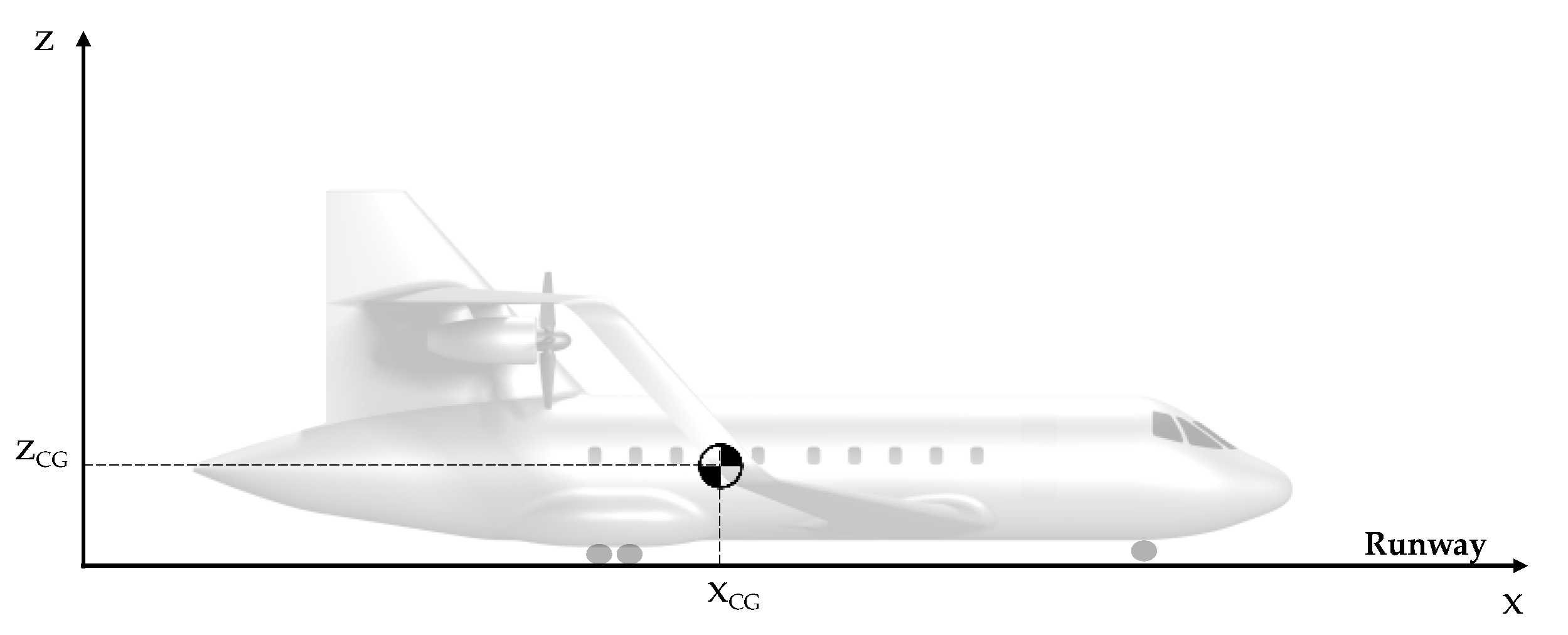
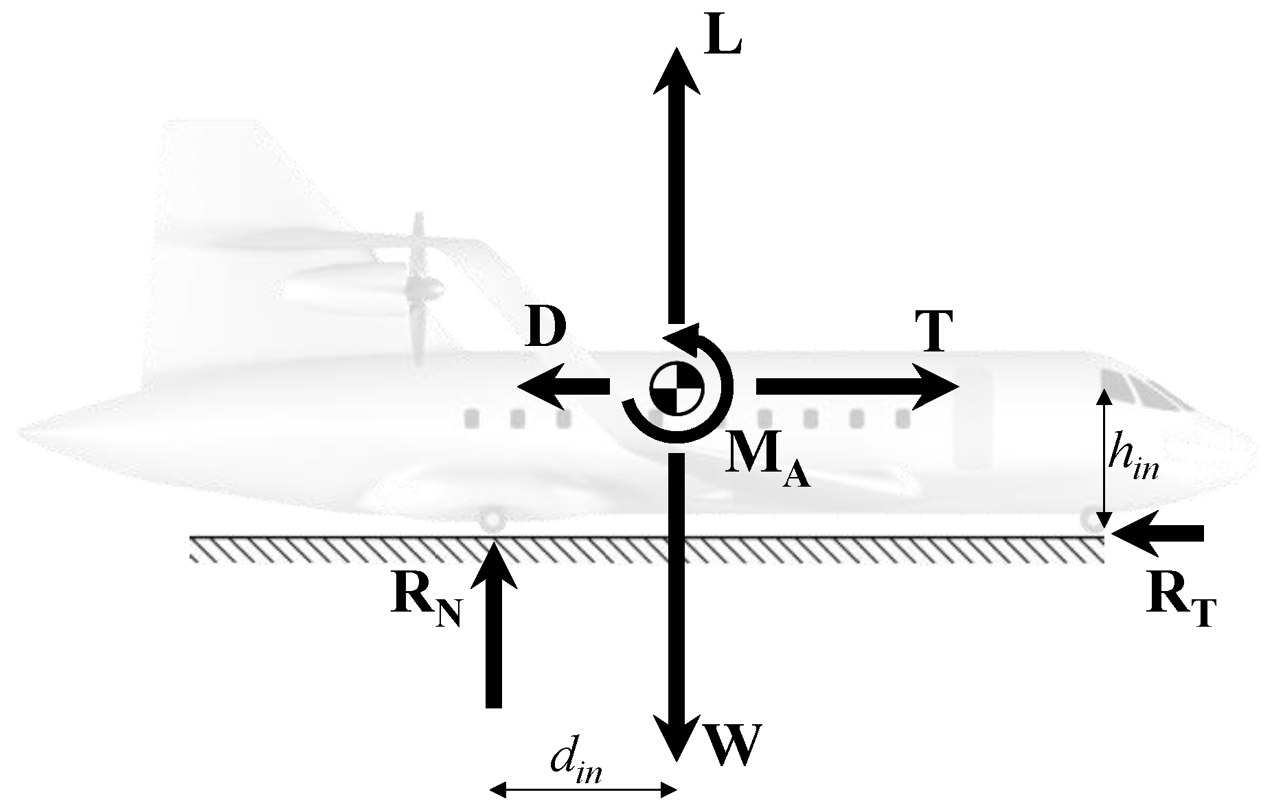
2.1. Equations of Motion

The aircraft take-off manoeuvre is characterized by two main stages, each of which can be mathematically described by a distinct set of ordinary differential equations. To derive the equations of motion an inertial reference frame which identifies the aircraft longitudinal plane is considered, see Figure 1. Specifically, the x-axis is oriented toward the direction of motion of the aircraft, and the z-axis is opposite to the direction of the standard gravity.
The first phase is known as the ground phase, which can be further subdivided into the ground-roll and rotation phases. During the ground-roll, the aircraft thrust is set to its maximum level to overcome both aerodynamic drag and the friction due to the contact of the tyres with the runway, leading to a progressive increase in the aircraft velocity. In this phase, the aircraft motion can be described by only one degree of freedom, its horizontal displacement; thus, the ground-roll motion can be described by Equations (1) and (2):
( W / g )   V ˙ x = T     D   R T
R N = W     L
where W is the aircraft weight, g is the gravity acceleration, Vx is the horizontal speed, T is the engine thrust, D and L are the aerodynamic drag and lift respectively, and RN and RT are the normal and tangential reaction of the ground, respectively; all the dynamic variables are functions of the time, and dotted variables indicate the time derivative of the considered quantity. RN and RT can be assumed proportional, by introducing the rolling friction coefficient μ, according to Equation (3):
R T = μ R N
μ is considered constant throughout ground-roll, neglecting the effects of speed and tyre pressure. The kinematic description of the ground-roll phase is provided by Equations (4)–(6):
x ˙ = V x
z ˙ = V z = 0
θ ˙ = q   = 0
where x and z are the horizontal and vertical displacement of the centre of gravity respectively, Vz is the vertical speed, θ is the pitch angle, and q is the pitch angular speed. As previously stated, the vertical and pitch degrees of freedom are suppressed during ground-roll, thus are fixed equal to zero. The subsequent rotation phase begins when the aircraft pitch angle reaches for the first time a value larger than zero; typically, this occurs at a designated velocity, called rotation speed VR, where the pilot increases the nose-up pitching moment by commanding the elevator deflection, and causing the aircraft rotation around its main landing gear. This introduces a second degree of freedom in the aircraft motion, the longitudinal pitch θ, and the related differential equations of motions become (Equations (7)–(9)):
( W / g )   V ˙ x = T cos θ   D   R T
R N = W     L     T sin θ
I y θ ¨ =   M A     R N d   R T h
where Iy is the aircraft longitudinal moment of inertia, MA is the aerodynamic pitching moment, and h and d are the vertical and horizontal distances of the centre of gravity from the landing gear, as schematically reported in Figure 2, where the subscript in indicates the initial position, i.e., referring to the centre of gravity position during ground-roll.
The position of the CG while θ varies can be calculated by means of simple trigonometry considerations, as reported in Equations (10) and (11):
h = h in cos θ + d in sin θ
d = h in sin θ + d in cos θ
The aerodynamic moment MA has a fundamental role in the manoeuvre evolution; it is computed according to the methods described in Section 3 and can be defined as in Equation (12):
M A = 1 2 ρ V 2   S   c   C M = 1 2 ρ V 2   S   c   ( C M α α +   C Mq q +   C M δ e δ e )
where ρ is the air density, V is the airspeed, S is the lifting system reference surface, c is the mean aerodynamic chord, C M is the total aerodynamic pitching moment coefficient, C M α is the pitching moment derivative with respect to the angle of attack α , C Mq is the derivative with respect to the pitch rate q, and C M δ e is the derivative with respect to the elevator deflection δ e . Specifically, C M α is related to aircraft pitch stiffness and depends on the relative longitudinal position of the centre of gravity XCG and the neutral point XNP, C Mq is related to aircraft pitch damping, and mainly depends on the lifting system design, and C M δ e is the command derivative, and is related to the sizing of the elevator. The assumption of quasi-steady aerodynamic is introduced in the model, so that the downwash lag effects on the aerodynamic pitching moment are neglected, namely by fixing equal to zero the C M α ˙ .
As this dynamic model is developed for the conceptual design phase, the longitudinal moment of inertia Iy is calculated by means of a simplified procedure, to avoid complex modelling of the geometry of each aircraft considered. Specifically, Iy is computed with a mass concentrated model, as sketched in Figure 3, where each aircraft component is considered as a concentred mass, with the exception of the fuselage whose moment of the inertia is calculated according to Huygens-Steiner’s theorem; consequently, aircraft moment of inertia is computed according to Equation (13):
I y   = m comp x comp 2 + 1 12 m f l f 2
where m and x identify the mass and the centre of gravity position of each component comp, respectively; referring to the Figure 3, the subscripts indicates: sys the cockpit system, fw the forward wing, rw the rear wing, lg the landing gear, p the propulsion system, vt the vertical tail, f the fuselage, for which lf indicates its length. The centre of gravity position of each component is referred to the aircraft centre of gravity.
The kinematic relations expressed by Equations (4) and (5) remain the same for the rotation phase, whereas the condition of Equation (6) becomes:
θ ¨ = q ˙
θ ˙ = q
as it is now possible for the aircraft to generate a pitch angular acceleration q ˙ . The gradual increase in pitch angle results in an increase of angle of attack and consequently of lift, while the normal reaction force exerted by the runway and the ground friction progressively decrease until they are null as the aircraft actually begins to fly; specifically, the beginning of the airborne phase occurs when the condition of Equation (16) is verified.
L + T sin θ     W
This condition represents the switch from the first stage of the manoeuvre, the ground phase, to the second one, the airborne phase; in this phase, also referred as transition to climb, the aerodynamic actions allow the aircraft to leave the ground and to follow a roughly circular path. According to the FAR 25.113 [56], at the end of the take-off manoeuvre the aircraft must reach a height at least equal to 35 ft, called screen height, with a prescribed speed; then, the aircraft can continue with the subsequent climb phase. For the transition to climb phase, also the vertical displacement of the centre of gravity is an active degree of freedom; the equations of motion describing this stage are Equations (17)–(19):
( W / g )   V ˙ x = T cos θ     D cos γ     L sin γ
( W / g )   V ˙ z = T sin θ + L cos γ     W     D sin γ
I y θ ¨ =   M A  
where γ is the angle of trajectory slope, defined as in Equation (20):
γ = θ     α
The kinematic relations expressed by Equations (4), (14) and (15) are still valid, whereas the condition related to the vertical displacement becomes:
z ˙ = V z
The aircraft dynamics schemes for the ground-roll, rotation, and transition to climb phases are reported in Figure 4; considering the x axes, the subscripts indicate, respectively: B body, H horizontal, V velocity.

2.2. Aerodynamic Model

The aerodynamic actions to be evaluated at each time-step of the dynamic model proposed in Section 2, are lift, drag, and pitching moment; a quasi-steady approach has been used. The general expression of the lift is:
L = 1 2 ρ V 2 S   C L
The lift coefficient C L is computed by means of the Vortex Lattice Method (VLM) implemented in the code AVL [57]; the same is for the computation of C M (Equation (12)) and for the induced drag coefficient C Di (Equation (23)). As widely detailed in Section 3, the AVL tool allows to model the ground effect aerodynamics, that has a significant influence on C L , C Di , and C M . Furthermore, in AVL movables and flaps can be modelled as plain surfaces, and their effect on aerodynamic forces, moments, and derivatives can be estimated. The expression for the drag is:
D   = 1 2 ρ V 2 S   ( C D 0 + C Di )
C Di is computed by AVL, whereas the parasitic drag coefficient CD0 is split as reported in Equation (24):
C D 0 = C D   wb + C D   lg + C D   f
where the wing-body parasitic drag C D   wb , which includes the contribution of lifting system, fuselage, and vertical tails, is estimated by means of the component build-up method proposed in Ref. [40], whereas the contribution of the landing gear C D   lg and flaps C D   f are evaluated with the method proposed in Ref. [58].
The sizing of movables and high-lift devices is performed by means of the procedures defined in Refs. [59,60]; the effect of the high-lift systems deployment on the maximum lift coefficient C L   max and on the take-off stall speed V s   TO are estimated by the model proposed in Ref. [59]. In this work, the elevator command is modelled in a simplified manner: once the aircraft reaches the VR, a step input to the command δ e is provided, and it is maintained constant until the end of the transition to climb.

2.3. Thrust Model

A simplified description has been used to model the thrust of the aircraft. Indeed, rather than simulating thrust as a function of speed, it is possible to use with sufficient accuracy mean values to be set as constants during the evolution of the whole manoeuvre, as reported in Ref. [44]. Specifically, according to Ref. [44], the average value of the thrust during the manoeuvre for a turbofan-powered aircraft can be evaluated according to Equation (25):
T = 0.75   5 + λ 4 + λ ( T max N e )
where λ is the engine by-pass ratio, T max is the maximum continuous thrust of one engine expressed in kgf, and N e is the number of engines. A similar simplifying assumption can be made for the generated thrust when considering propeller-driven aircraft; according to Ref. [44], the average thrust during the take-off can be evaluated using Equation (26):
T = 5.75 P i 0 σ   N e   d p 2 P i 0 1 / 3
where P i 0 is the installed power of one engine expressed in hp, d p is the propeller diameter expressed in ft, and σ is the ratio ρ/ρ0 between the air density at the airport height and the air density at sea level. The formula of Equation (26) provides an output in lbf.
Such thrust modelling allows for very simple simulation of one-engine-failure manoeuvres, simply by subtracting at instant t = t failure the thrust share T relating to the non-operating engine.

2.4. Simulation Technique

The high level of non-linearity and the strong coupling among the aircraft degrees of freedom, make a direct solution of the dynamic problem very complex, thus requiring an approximate numerical approach. Indeed, mathematical problems based on a set of ordinary differential equations can be resolved through a discretization process, which involves the subdivision of the time domain into small intervals Δ t , and the approximation of the time derivatives as reported in Equation (27) for a generic time-function y:
y ˙ = d y d t   y ( t + Δ t )   y ( t ) Δ t
For the integration of take-off equations of motion, this study adopted a numerical approach using the Euler forward method, described by Equation (28):
y ( t + Δ t ) = y ( t ) +   y ˙ ( t )   Δ t
A general scheme of the overall simulation framework is reported in Appendix A.

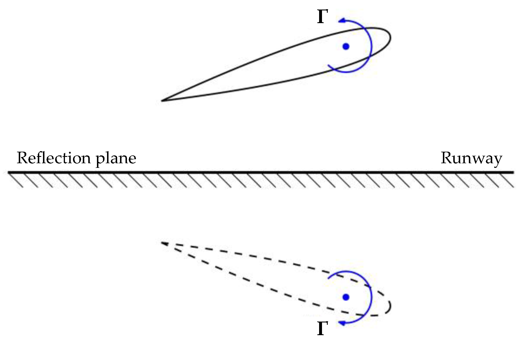
3. Ground Effect Aerodynamics

The term “ground effect” typically denotes the phenomenon whereby the airflow surrounding an aircraft is influenced by its proximity to the ground; the presence of the ground modifies the flow field around the aircraft, impacting on its aerodynamic and aeromechanic features [61]. Specifically, the interaction of the ground with the flow fields has two main implications: from one side, the presence of the ground physical barrier introduces overpressures on the lifting surfaces, causing an increase of its lifting capability; this effect is also known as ‘air cushion’. On the other hand, the presence of the ground modifies and weakens the vorticity field (both for wake and wing tip), causing a reduction of induced drag, in an effect also called ‘vortex breakdown’. The intensity of the ground effect depends on the aircraft size, wings shape, and its relative position with respect to the ground; indeed, the clearance between the wing and the runway plays a key role. The ground effect increase in lift and reduction in drag may be exploited to improve the take-off field performance of the aircraft, mainly in terms of possible reductions in required take-off distance; however, it is an aerodynamic phenomenon to be deeply analysed, as it can modify the whole aeromechanic layout of the aircraft, introducing aeromechanics modifications that may lead to unacceptable unstable behaviour during the manoeuvre. These aspects are carefully detailed in Section 3.3, in which test-cases are used as examples to discuss the influence of ground effect on aircraft aerodynamic derivatives.
There are different ways to take the ground effect into account during aircraft conceptual design. Analytical methods, as that proposed in Ref. [62], are usually the most suitable ones when dealing with the early stage of the design process, and these are useful to identify the macroscopic physical features of the phenomenon, but in the case of ground effect aerodynamics, these approaches may be unreliable especially when facing analyses regarding complex geometrical models or unconventional lifting architectures. To better face this latter circumstance, higher-fidelity models are needed, as numerical investigations [63,64,65], or experimental studies [66] and related validation procedures [67], that are not suitable for conceptual design studies, as they are very expensive and/or time consuming.
In this work, to evaluate the ground effect on aircraft aerodynamics during take-off, a Vortex Lattice Method (VLM) model has been employed; this method allows to effectively evaluate the aerodynamics of different lifting architectures while maintaining low computational times. Potential and limitations of the use of this method to evaluate ground effect are detailed in Section 3.1.

3.1. Evaluation of Aerodynamic Performance

The Athena Vortex Lattice (AVL) software is designed to conduct aerodynamic and flight mechanics evaluations of rigid aircraft of any architecture, whether conventional or not; it utilizes a VLM model for analysing the aerodynamics of lifting surfaces. The VLM is a suitable method for calculating the aerodynamic properties of wings and the interaction between multiple lifting surfaces during the aircraft conceptual design; indeed, the AVL can be extensively used to assess lift curve slope, induced drag, neutral point longitudinal location, steady stability derivatives. The primary advantage of this type of aerodynamic solver is its computational efficiency, as it can generate results for a broad range of aircraft configurations and operating conditions in a short computational time. As VLM is a surface potential panel method based on the solutions of Laplace’s equation [68], its main limitation is related to the impossibility to investigate the effects of viscosity, or its unreliability for high angle of attack conditions, near the stall. On the other hand, AVL allows for an in-line with the theoretical assumptions modelling of the ground effect aerodynamics (a theory that is detailed in the related technical literature [62,69,70,71,72]); indeed, as described in Ref. [62], potential flow can be used to model an aircraft in ground effect by substituting the ground’s surface with the aircraft reflected image, thus imposing a symmetry condition on the reflection plane (Figure 5); the downwash of the aircraft is mirrored by the upwash produced by its reflected image, thus, by symmetry, there can be no flow normal to the plane of reflection. Therefore, the potential flow generated by the aircraft and its mirrored image is equivalent to that generated by the aircraft and a flat solid surface representing the ground, as proposed by the theoretical formulation of Wieselsberger [62,69].
The aerodynamic performance in ground effect depends on the vertical clearance Δz and the pitch attitude θ of the aircraft with respect to the ground. Regarding the effect of the vertical positioning, it is sufficient to translate the aircraft model in AVL. Difficulties arise when evaluating the effects of θ, as the condition of ground symmetry does not allow to introduce a corresponding angle of incidence α to the asymptotic flow. To simulate the pitch attitude, it is therefore necessary to maintain α = 0° and to physically rotate the input geometry in AVL of an angle equal to θ. During the take-off rotation phase, the aircraft rotates around its main landing gear, and the geometry of the lifting surfaces is rotated according to the relationship in Equation (29):
x fin z fin = cos θ sin θ sin θ cos θ x in   x r z in z r + x r z r + Δ z
where, considering a reference coordinate system in the vertical plane having origin in the aircraft nose, x in   and z in   represent the initial coordinates of a generic point of the lifting system, x r   and z r are the coordinates of the centre of rotation (the landing gear in this case), x fin   and z fin   identify the final position of a generic point after a rotation of an angle equal to θ ; the vertical displacement Δz is equal to zero during the rotation phase of the take-off manoeuvre. In the transition to climb phase, instead, the centre of rotation becomes the aircraft centre of gravity, and the Δz is fixed equal to the vertical displacement of the aircraft. An example of box-wing geometry subject to rotation within AVL to take into account for aerodynamics in ground effect as θ varies is proposed in Figure 6.

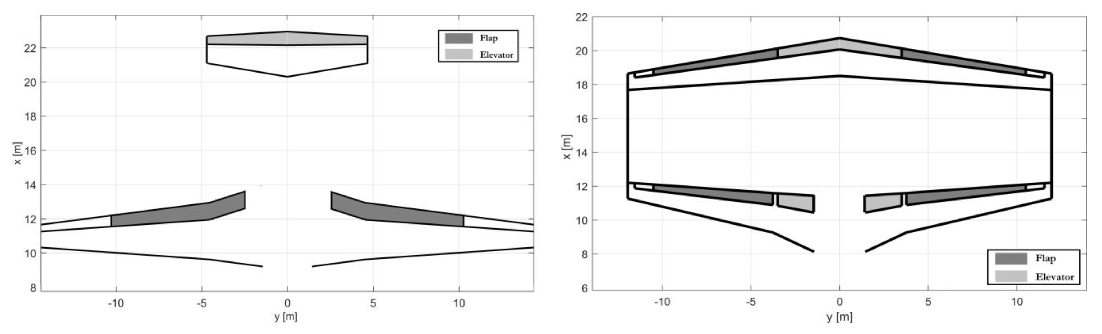
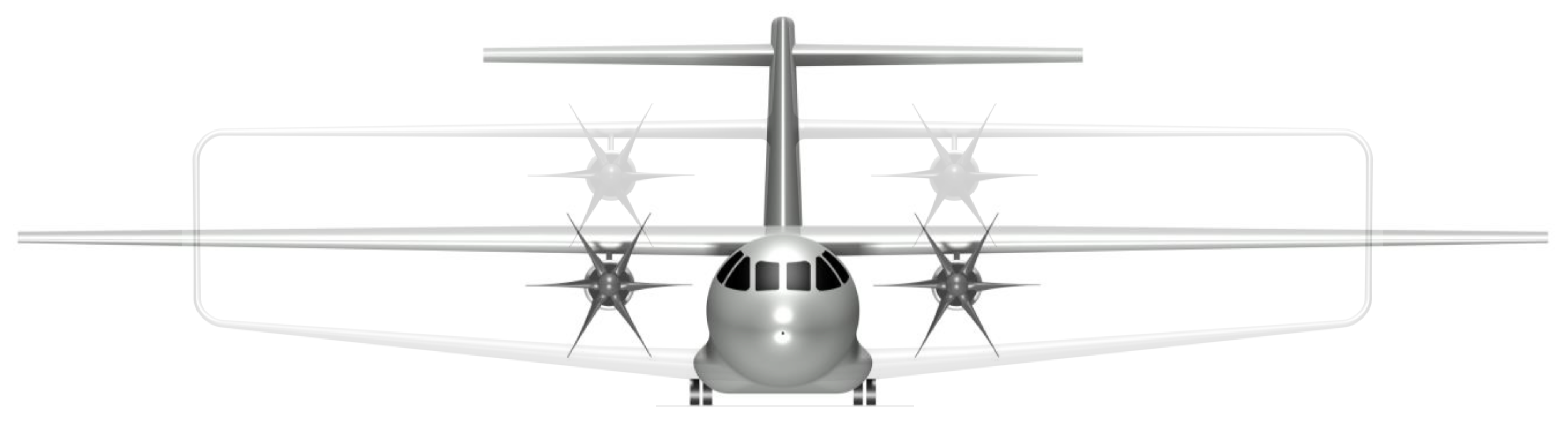
3.2. Test-Case Configurations

As mentioned in Section 1, the purpose of the take-off simulator presented in this study is to be versatile enough to be used in the conceptual design of even innovative and unconventional aircraft, as many of which are currently the subject of intense investigations. To support this proposition, two different test-case aircraft are analysed in this paper: both belonging to the regional category, one is a tube-and-wing (TW), the other is a box-wing (BW) aircraft. The aircraft selected for this analysis represent two possible solutions for the application of hybrid-electric (HE) propulsion, on which much research is currently being developed; in particular, the TW test-case represents the output of the research on hybrid-electric regional aircraft proposed in Ref. [73], whereas the BW configuration, described in Ref. [45], represents an evolution in which the airframe, in addition to the propulsion, is also a technological novelty [74]. Figure 7 and Figure 8 show front views of the two configurations, Figure 9 reports their planforms, and Table 1 lists their main features.
The selection of these two test cases is motivated from different standpoints; primarily, there are architectural and aeromechanical differences that make the comparison between the take-off manoeuvres of the two configurations interesting. A main architectural difference with respect the ground effect aerodynamics lies in the vertical location of the lifting surfaces; the TW regional aircraft, in fact, has a high main wing mounted on the top of the fuselage, following the typical arrangement of current turboprop regional aircraft [75,76], whereas the front wing of the BW is very close to the ground. It should be noted that the front wing of any BW aircraft is the one that generates a larger portion of the total lift, hence has the larger wing loading L/S (Table 1), as proven in Ref. [59]; this is necessary to meet the BW stability and controllability requirements in different operating conditions; for this reason, the front wing of the BW will hereafter be identified as its main wing. Having a main wing much closer to the ground may change the impact that ground effect has on the aerodynamic performance of the BW, compared to the high-wing configuration of the TW. A further difference between the two configurations lies in the pitch control: the TW aircraft has a traditional elevator placed at the trailing edge of the horizontal tail (Figure 10 left), that introduces pull-up pitch moment by generating downforce; the BW aircraft has a pair of elevators, placed in the root zones of both wings (Figure 10 right), which are activated in counter-rotation. In this way, by properly sizing the elevators, it is theoretically possible to generate pull-up moment without introducing any downforce. Furthermore, as schematised in Figure 11, the positioning of the flaps also differs between the two architectures; the TW may have flaps following the span of the main wing, whereas the BW may have properly sized layouts to have flaps on both wings.
These differences are therefore reflected in the design variables that affect the take-off manoeuvre; among the main ones selected in this work, there are three in common between the TW and BW configurations, namely the flap deflection on the main wing δ f , the deflection of the elevator δ e (considering the one on the main wing for BW), and the speed at which the elevator is deflected, defined as the rotation speed V R . The BW configuration, however, has two additional variables, correlated with the option of having movable surfaces and flaps also on the rear wing; specifically, it is introduced the flap gain ψ defined as the ratio between the deflection of the rear flap δ fr and that of the main flap δ f (Equation (30)), and elevator gain ε defined as the ratio between the deflection of the rear elevator   δ er and that of the main elevator δ e (Equation (31)).
ψ = δ fr δ f
ε = δ er δ e
The tool presented in this work, as it can simulate pitch dynamics and can assess the ground clearance impact on the aircraft’s aerodynamic performance, is therefore able to properly evaluate the aeromechanical differences between the two proposed lifting architectures. As an additional side note the proposed case studies represent possible novel solutions for the integration of hybrid-electric propulsion in the regional sector: for this category of aircraft, being able to meet the stringent requirements on take-off runway lengths is fundamental [77], and the simulation tool presented in this work can represent an effective method for assessing this performance right from the initial design phases.

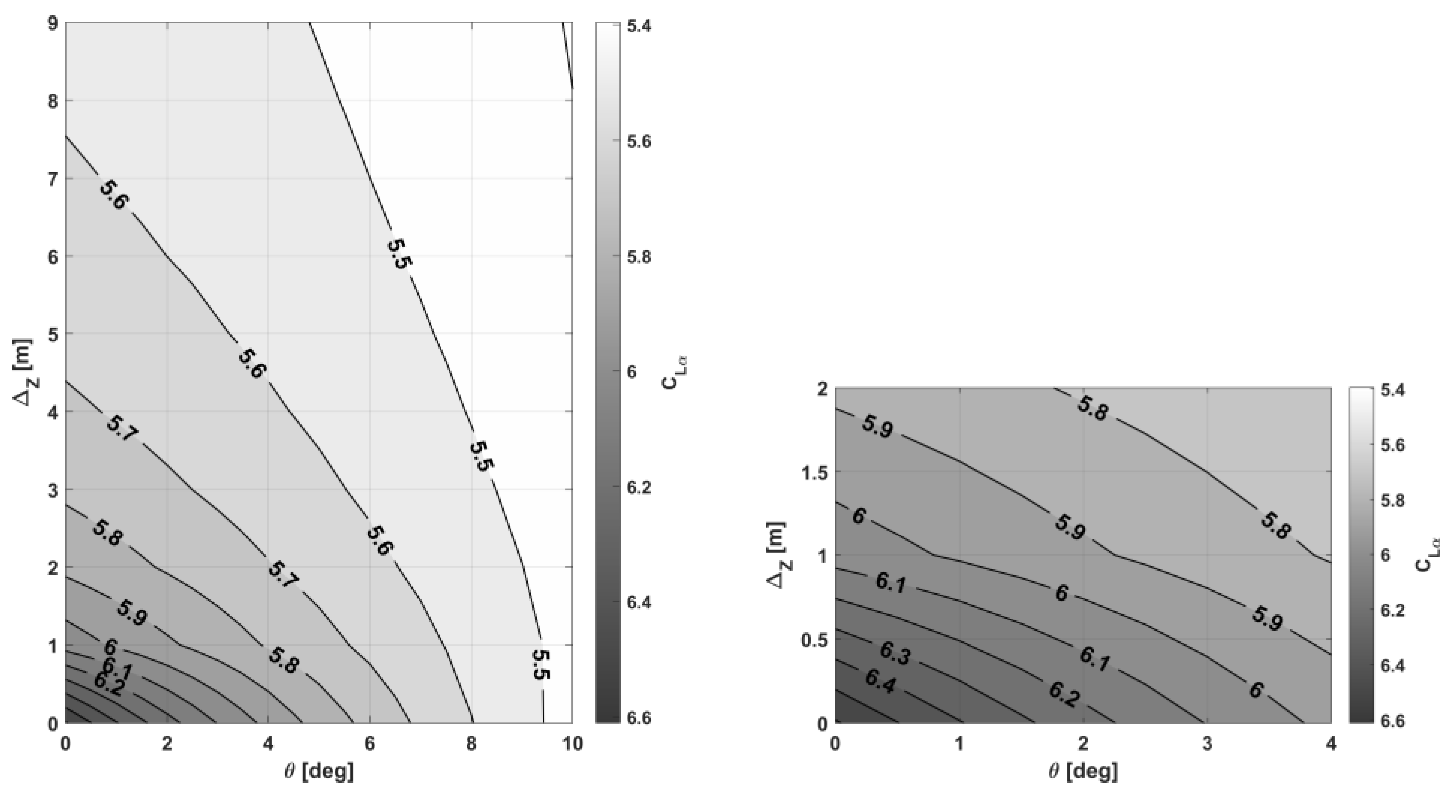
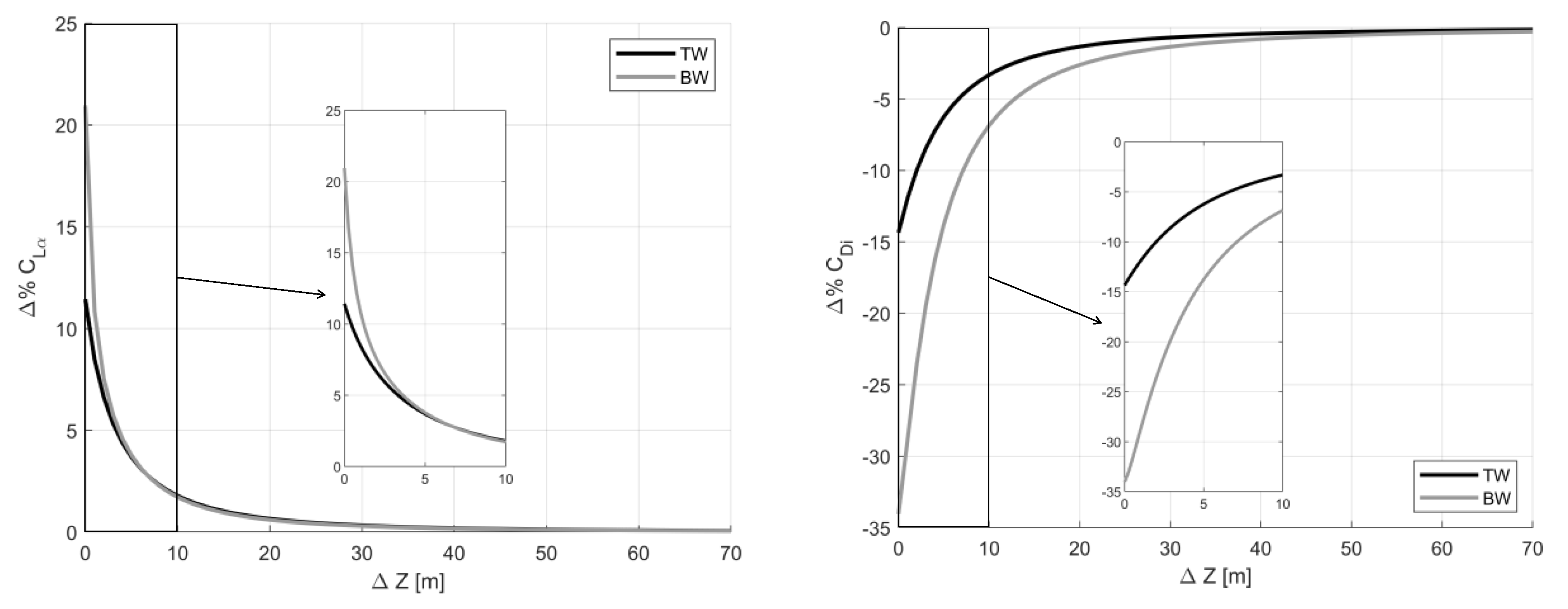
3.3. Analysis of the Impact of Ground Effect on Aerodynamic Performance

As detailed in Section 3, the ground effect mainly depends on the clearance and the attitude of the lifting system with respect to the ground. Considering the BW configuration without any flap deflection (‘clean’ layout), a sensitivity analysis of the aerodynamic performance in ground effect (IGE) has been performed by varying vertical distance of the centre of gravity (Δz) and aircraft attitude (θ) within the AVL solver, and imposing the symmetry boundary condition on the runway plane. In the following the main aerodynamic coefficients trends IGE are reported and discussed. The contours in Figure 12 highlight the C L α derivative correlation with Δz and θ; specifically, as the aircraft clearance with the ground reduces decreasing Δz, C L α increases, as the wings ventral overpressures due to the presence of ground increase. This effect is not linear with Δz, and becomes more pronounced for small distances between the main lifting surface and the ground, as highlighted by the diagram enlargement in Figure 12; for this reason, the BW configuration can take advantage in lifting enhancements as the main wing is very close to the ground. A second effect that is evidenced in Figure 12 is that the C L α IGE clearly depends on the angle of attack α (that in this sensitivity study coincides with θ), whereas this is a negligible effect in free air. Indeed, in IGE conditions, as the aircraft rotates, the BW main wing moves away from the runaway whereas the rear wing approaches the ground; since the main wing is the most affected by the ground effect due to the closer distance to the runaway, a change in aircraft attitude leads to reductions of lifting capabilities.
Hence, when Δz tends to zero, an aircraft rotation θ implies that C L α of the front wing reduces, and the C L α of the rear wing increases, causing a pitch stiffening, as can be read from the C M α -α graph in Figure 13; with the increase of the distance of the aircraft from the runway, this effect disappears. Furthermore, if we considered the levelled condition θ = 0°, it is noted that moving from free air to the ground, namely reducing Δz, the aircraft C M α gradually reduces for distances very close to the ground; this, because the main wing C L α increases more than that of the rear wing, implying a movement forward of the neutral point. Even if this behaviour is not general, as depends on the geometry of both wings (sweep angles, twist distribution, taper ratio, etc.), it is an indication on how the ground effect can affect the longitudinal stability features of a configuration, even in a non-conservative way. So, it is necessary to properly take the ground effect aerodynamics into account even in the early stages of the aircraft take-off performance assessment, to avoid unfeasible or not consistent situations.
Another significant aerodynamic effect of the ground proximity is the reduction of the wake and tip vorticity; as previously stated, this causes a reduction of overall wake vorticity, hence a reduction of downwash, resulting in a reduction of induced drag. Figure 14 shows the trends of the induced drag coefficient C Di , as the aircraft approaches the ground and varies its pitch attitude; the induced drag reduction due to the ground effect quickly disappears as Δz increases, and it is more evident for large pitch attitudes, in correspondence of which the lift coefficient is larger.
In the following, a comparison of the aerodynamic performance IGE between BW and TW is proposed; specifically, the air cushion and vortex breakdown effects are compared. In Figure 15-left, the comparison between TW and BW in terms of percent variation of C L α approaching the runway (i.e., reducing Δz and fixing θ = 0°) with respect to the free air value is presented. It is noted that the effect of lifting capabilities increase IGE is more pronounced for the BW, that for Δz = 0 exhibits an increase of C L α IGE of about 21%, whereas the TW expresses an increase of only 12%. A same better performance of the BW is readable from the percentage C Di IGE reduction with respect to the free air condition (Figure 15-right); BW exhibits a reduction up to the 34% when Δz = 0, while TW shows a reduction of about 14%. These effects are mainly attributable to the vertical position of the main wings of the two configurations; as highlighted in Figure 16, the BW has a main wing significantly closer to the ground, hence enhancing the influence of the ground effect on aerodynamics.

4. Simulations Results

A first investigation on the take-off manoeuvres of BW and TW regional aircraft has been carried out in order to identify the aeromechanical peculiarities of the two lifting architectures; firstly, we focused on the analysis of manoeuvre evolution and performance by varying only the flap deflection δ f (and the flap gain ψ for BW only), while in Section 5 a wider optimisation involving the other variables such as V R , δ e , and ε , is proposed. The take-off simulations have been performed according to the standard conditions defined by the following assumptions: the departure airport is located at sea level, and the standard air model is used; the engines supply their maximum available power, according the model of Equation (26), during the whole manoeuvre; the runaway is considered dry; the entire manoeuvre develops in the longitudinal plane, so any lateral wind is ignored. The selected V R is equal to 1.15 V s   TO , whereas a δ e = 25° is fixed; for the BW configuration, a value of ε = −1 is considered.

4.1. Box-Wing Aircraft Aeromechanics Features during Take-Off

This section discusses the results for the BW regional aircraft take-off simulations. The results here proposed, obtained using the simulation set-up described in Section 2, are intended to outline in a general way the aeromechanical properties of BW architecture aircraft during the take-off phase. Before going through the dynamic analysis, the aerodynamic performance of the BW flapped configuration is presented; these, are calculated using the methods described in Ref. [59], and are evaluated by varying δ f = [ 10 °   20 ° 30 ° ] and ψ = [ 0   0.25   0.5   0.75   1 ] ; Figure 17 shows the trends of the maximum lift coefficient of the aircraft C Lmax and the related take-off stall speed V s   TO as δ f e ψ vary. It is observed that, as both δ f and ψ increase, there are increases in C Lmax (Figure 17 left); it is also observed that, and this is of general validity for BW configurations as demonstrated in Ref. [59], the deflection of the flap on the front wing is more influential than that on the rear wing. The performance in terms of V s   TO (Figure 17 right) follows that of C Lmax , decreasing when C Lmax increases according to the Equation (32):
V s   TO = 2 W / S ρ   C Lmax
where the weight W is fixed equal to the MTOW.
The aerodynamic coefficients C L and C M of the flapped BW configuration are shown in Figure 18. The trend of C L is increasing with both front and rear flap deflection; C M shows interesting dependences on flap deflections on both wings. The deflection of only the front flap   δ f (therefore fixing ψ = 0), causes an increase in the aircraft’s pull-up moment, as the main wing is placed in front of the centre of gravity. By increasing ψ , and therefore introducing the interdependence with the deflection of the rear flap, which is located much further back with respect to the centre of gravity (Figure 11 right), this pull-up effect is gradually attenuated, and becomes null at the equilibrium condition in pitch C M = 0; by further increasing ψ , the nose-up pitching effect induced by the deflection δ f becomes secondary to the nose-down effect due to the rear flap deflection δ fr . If we focus only on the trend of ψ , thus fixing   δ f , we can see the significant effect that the deflection of the rear flap has on the pitching moment, which passes from decisively nose-up for ψ = 0, to decisively nose-down for ψ = 1; for a BW configuration, therefore, the deflection of the flaps has a much more pronounced aeromechanical effect than for traditional lifting architectures, and this must be properly considered in the study of the take-off manoeuvre.
As detailed in Section 2, the simulator developed in this research is capable of taking the aspects previously described into account in a general manner. In the following the simulations results obtained for the BW configuration are commented, for which it was fixed   δ f = 30° and it was varied ψ = [0 0.25 0.5 0.7 1]. Figure 19 left shows the results of the simulations for the BW in terms of centre of gravity trajectory, from which it is possible to evaluate the runway length required to complete the take-off manoeuvre; it can be seen that increasing the ψ results in increases in the required runway length, and therefore in a deterioration of performance, despite the deployment of the rear flap increases the C Lmax (Figure 17). The worsening of the take-off performance as ψ increases is related to its effect on pitching moment, which is more predominant than the beneficial effect in terms of increasing C Lmax . To further investigate this aspect, let us consider the graph in Figure 19 right, which shows the evolution of the aerodynamic pitching moment M A during the manoeuvre; it can be observed that, as ψ increases, ground-roll C M of the aircraft gradually decreases, until it changes sign and becomes nose-down. This condition makes the elevator command δ e , activated once the V R is reached, less effective, since it must overcome a pitch-down moment in opposition to its action.
In other words, more negative is the ground-roll C M , lower is the angular acceleration q ˙ introduced by the activation of the elevator command, and therefore the development of the manoeuvre is slower, resulting in an increase of the necessary runway length. The results in terms of q ˙ , and the subsequent angular velocity q, are shown in Figure 20; as far as q ˙ is concerned (Figure 20 left) an enlargement around the point of activation of the δ e control has been provided in order to ease the visualisation of the comparison, and to avoid visualising only superimposed q ˙ spikes; the slight difference between the distance of activation of the control, and therefore of the introduction of an instantaneous q ˙ , is due to the larger aerodynamic drag that is introduced by increasing ψ , and therefore to a later reaching of V R . The simulator also provides the trend of q following the actuation of the δ e control (Figure 20 right), and thus of the introduction of an instantaneous q ˙ acceleration, which is in agreement with the theory of second-order dynamic systems (Equations (14) and (15)): as a result, the pitch angle θ increases as a ramp function. As a quasi-steady aerodynamics approach has been employed, due to the features of the solver used to perform the aerodynamic evaluations (AVL), the downwash lag effects related to the time derivative of the angle of attack α ˙ have been neglected in the evaluation of the pitch dynamics during the rotation phase.
However, the analysis of the BW pitching dynamics is still incomplete; in fact, by analysing in detail the evolution of the aerodynamic moment in Figure 19 right, it is observed that for cases in which ψ is very low, the C M of the BW can become largely positive, due to the advanced position of the main wing. Very high positive values of ground-roll C M can result in large pull-up moments as the ground-roll speed increases, which can overcome the reactive moments even before the elevator is activated, causing the aircraft to rotate before reaching the preselected V R . In particular, referring to Figure 21, this condition occurs when the relationship in Equation (33) is verified:
M A     M R
With
M R = R T h in R N d in
Figure 22 left shows the aerodynamic moment ( M A , continuous line) and the reaction moment ( M R , dashed lines) of the considered take-off simulations; when the two moments become equal, the pitch dynamics is initialised without the need to activate the elevator. In the instants following the point at which   M A = M R , the pitch angle θ begins to increase and the aerodynamic moment   M A to decrease (Figure 22 right) due to the effect of the aerodynamic damping in pitch. The early beginning of the pitch dynamics could already be read in the trend of the pitch angular speed q proposed in Figure 20 right, where it can be seen that for ψ equal to 0 and 0.25, this variable starts to increase before the elevator control is activated.
We can then define a new V-speed, i.e., the effective rotation speed V Re , which corresponds to the speed for which the condition θ > 0 occurs the first time; in our BW test-case, this speed for values of ψ = [0, 0.25], results to be lower than the pre-selected rotation speed V R , as can be seen in Figure 23.
Even if this aspect could appear having a beneficial impact on the required runway length, it hides some pitfall: anticipating the actual V R may lead to values of V Re smaller than the decision speed V 1 , that is a condition not acceptable for a civil transport aircraft; furthermore, this may lead to a pitching behaviour not directly controlled by the pilots, thus it is definitely a condition to be avoided in standard operations.

4.2. Tube-and-Wing Aircraft Aeromechanics Features during Take-Off

In this section, the results of the take-off simulation of the regional TW are presented. In this case, the outcomes are more direct than that of the BW, as the performance and aeromechanical correlations are intuitive. Figure 24 shows the trends of C Lmax and V s   TO as δ f varies; the beneficial effect of δ f on the increase of C Lmax and the correlated reduction of V s   TO according to the relationship in Equation (32), is clear.
Figure 25 left shows the TW centre of gravity trajectory, and thus the required runway lengths, as δ f changes; there is a direct correlation between the increase in δ f and the reduction in runway required for take-off. For the considered TW configuration, C M is always negative in ground-roll; the effect of flap deflection, for this specific test case, results in a decrease in absolute value of nose-down C M , therefore δ f introduces a gain in both lift and pitching moment.

5. Optimization Results

In this section, the results related to an optimization framework developed to minimize the take-off field length is presented. Specifically, Section 5.1 describes the developed optimization framework, Section 5.2 presents the comparison between the BW and TW optima take-off performance, and Section 5.3 highlights the influence of the ground effect aerodynamics on the take-off performance and kinematics.

5.1. Optimization Procedure

As described in Section 3.2, the selected variables to assess the take-off dynamics are { δ f , ψ , δ e , ε , V R } for the BW, and { δ f , δ e , V R } for the TW. These parameters, in the following referred as initial layout, could affect the take-off performance, thus, an optimization procedure has been set-up in order to find the optimum initial layout to minimize the required take-off length X TO ; the optimization problem is detailed in Equations (35)–(38). Specifically, Equation (35) refers to the minimization of the objective function X TO ; Equation (36) defines the design space, as ξ identifies the vector of the design variables, and l b   and u b are the lower and upper boundaries of the possible ξ variations; finally, Equations (37) and (38) identify the constraints: Equation (37) imposes that the final take-off speed V ( t end ) is larger than k V 2 times the take-off stall speed V s   TO , as prescribed by FAR 25.113, and Equation (38) does not allow aircraft rotations before the actual δ e command of the pilot.
min ( X TO ( ξ ) )
over
l b     ξ   u b
subject to:
V ( t end )     k V 2 V s   TO
V R   e = V R
Table 2 summarizes the design space defined for the optimization of the initial layout of the BW and TW configurations. The variable V R is not handled in absolute terms, but it is introduced as a fraction k V R of V s   TO (Equation (39)), as this latter varies with δ f and ψ .
V R = k V R V s   TO
To search for the optimum solution a multi-start procedure coupled with gradient based optimization algorithm, based on the sequential quadratic programming SQP [78,79,80], has been adopted. The SQP algorithm has been selected since it is widely adopted to solve non-linear optimization problems subject to equality and/or inequality constraints.

5.2. Comparison of Box-Wing and Tube-and-Wing Optima Take-Off Performance

This section presents the results of the optimization procedure described in Section 5.1; specifically, Table 3 shows the outputs of the optimization, in terms of optima design variables and objective function. From these results, it can be seen that the BW configuration has its optimum in correspondence of the design boundaries; the BW exhibits a required runway length that is 5.1% shorter than the corresponding TW configuration.
In Figure 26, a more detailed comparison of the evolution of aerodynamic and kinematic parameters during the take-off manoeuvre of the TW and BW configurations is presented; using the overview of Figure 26 as a reference, the main aeromechanical differences between the two architectures are observed and discussed in the following. From an aerodynamic point of view, it is observed that the TW configuration has a much higher ground-roll C L , due to the fact that the flap extends on the entire main wing, which has much more surface area than the BW main wing; in fact, for the BW, since the optimum ψ is equal to zero, the high-lift effect in terms of lift increase is only due to the contribution of the main wing. Thus, to the increased lifting effect associated with flap deployment, for TW there is also a significant increase in ground-roll C D , mainly attributable to the induced drag. This increase in ground-roll drag D, results in a slower acceleration curve V ˙ for the TW, since the thrust values for both configurations are nearly equal (see Table 1). The higher V ˙ for the BW allows to reach the pre-set V R earlier than the TW, and thus to activate first the elevator to engage the pitch dynamics. As described in Section 4, the activation of the control introduces a quasi-impulsive angular acceleration q ˙ , which results in the development of an angular velocity q that leads to an aircraft rotation θ that develops on a ramp during the manoeuvre. The rotation phase of the BW configuration is longer since the aircraft has to develop the necessary angle of attack α to reach the proper C L values to satisfy Equation (16). For the TW, the angle α required to reach this condition is smaller due to the already discussed larger ground-roll C L . It is also worth noting the influence of C M and moment M on the rotational dynamics: the BW configuration starts with positive C M , which thus favours the pull-up action introduced by δ e , while the opposite happens for TW. The magnitude of the pitching moment M during the rotation phase is mainly affected by the pitching stiffness, which can be identified by the derivative C M α , the damping that can be correlated with the derivative C Mq , and the control effectiveness identified by the control derivative C M δ e . The pitch stiffness C M α is related to the stability margin MoS of the aircraft; the assumption made in this work is that both BW and TW configurations start the manoeuvre with the same MoS, so the C M α is derived accordingly. The discussion on the pitch damping C Mq is different, since the architectural characteristics of the two configurations have fundamental relevance, as described in detail in Ref. [81]; in particular, the longitudinal disposition of the lifting surfaces of a generic BW configuration, longitudinally separated and distant from the aircraft centre of gravity, makes that configuration more sensitive to perturbations in angular velocity q and therefore exhibits much larger pitch damping than a corresponding TW. In this work, the ratio between the C Mq derivatives of TW and BW, evaluated with AVL, is about 1:3 at the beginning of the ground-roll. The control derivative C M δ e , on the other hand, can be considered to be architecture-independent; although the layout of the movable surfaces is very different, its efficacy is related to the low-speed controllability requirements used as a sizing reference [59]; in this work, the C M δ e of the BW is 1.3 times that of the TW.

5.3. Comparison of Performance In-Ground-Effect and Out-of-Ground-Effect

In this section, a comparison of take-off performance between the actual aerodynamic case, i.e., affected by the presence of the ground (IGE), and the case in which the ground reflection condition is turned off in the aerodynamic solver (out of ground effect, OGE), is proposed. The purpose of this comparison is to highlight the impact of considering the ground effect on the overall take-off performance. The comparison between IGE and OGE for the optima initial layouts exhibits qualitatively the same trends for BW and TW, whereas the magnitude of the IGE effect is different for the two configurations (Figure 27 and Figure 28); this is because, as seen in Section 5.2, the C L of the considered TW configuration is higher than the BW, resulting in different quantitative IGE aerodynamic responses. The absence of the ground effect, as seen by describing its theoretical aspects in Section 3, and as also readable in the graphs in Figure 27 and Figure 28, has the effect of decreasing the lift of the aircraft and increasing its drag. Since in the two conditions the maximum available thrust is the same, increases in D result in lower accelerations, and thus in a delayed attainment of the preselected V R . Reductions in L, on the other hand, result in a longer rotation phase, required to develop a larger angle α to generate the lift needed to satisfy the condition of Equation (16). Both effects contribute to an overall deterioration of take-off performance in terms of required runway, for both configurations; an increase in runway of 2% is estimated for BW, 10.5% for TW.

6. Conclusions

This article presented a take-off simulation framework suitable for use in the aircraft conceptual design phase. The main features of this simulator are the possibility of analysing aircraft of any aerodynamic configuration, assessing their aerodynamic performance considering the ground effect, and evaluating their dynamics as rigid aircraft in the longitudinal plane. The possibility of simulating aircraft of any airframe, together with the versatility and low computational cost of the model, make this simulator adequate to support the conceptual aeromechanical design of innovative aircraft. In support of this proposition, the aerodynamic and aeromechanical analysis of two regional aircraft with different lifting architectures have been presented: one with a conventional tube-and-wing configuration, with its main wing mounted high on the fuselage, and one with a box-wing lifting architecture. In the paper, the aerodynamic and aeromechanical differences between the two configurations in the proximity of the runway have been highlighted, underlining how the ground effect, depending on the shape of the wings and their positioning with respect to the ground, can both provide benefits in terms of lift and drag, but can also introduce substantial modifications to the longitudinal stability of the aircraft. By means of a sensitivity analysis to the main aeromechanical parameters in the take-off phase, conducted by means of the simulator developed in this work, the kinematic and dynamic properties of the box-wing configuration have been characterised, as they can differ substantially from those of traditional aircraft. Furthermore, through an optimisation procedure involving the take-off layout of the two configurations, a kinematic and performance comparison was made between the tube-and-wing and box-wing, which allowed to assess and generalise the main differences. The features that differ between the two configurations, carefully detailed in this article, are several; the geometry of the lifting system significantly affects the aeromechanical behaviour, from the control, which for the box-wing configuration is carried out by couples of elevators placed in front and rear of the centre of gravity, to the high-lift systems placed on both wings. The position of the front wing, located very close to the ground, provides a greater sensitivity to ground effect, offering the lifting system general aerodynamic advantages in terms of lift and drag. The wings arrangement in the horizontal plane, and the layout of the moveable surfaces and flaps, introduce substantial differences in pitch dynamics; by properly optimising the design variables that influence the take-off manoeuvre, the box-wing configuration can offer performance advantages in terms of required runway length.
The simulation framework still has some aspects that can be integrated in a further development from its current state; first, a thrust model, specific for turbofan and turboprop engines, with a characterisation of performance as speed, airport altitude and fan/propeller dimensions vary, would bring higher accuracy than the current constant-thrust model. An integration of a simplified model to take into account also the non-steady aerodynamic effects, as the downwash lag related to the time derivative of the angle of attack, can increase the accuracy of the ground effect aerodynamic evaluations; also the application of unsteady VLM may be a suitable development for the presented simulation framework. Furthermore, it is possible to consider modelling the elevator command not only as a step function but with specific time functions properly calibrated to the kinematic parameters of the manoeuvre, to emulate the actual pilot/control system behaviour. The evaluation of lateral dynamics, to also consider the potential occurrence of lateral wind gusts, can contribute to increase the comprehensiveness of the simulation package.

Author Contributions

Conceptualization, K.A.S., G.P. and M.B.; methodology, K.A.S. and G.P.; software and validation, K.A.S. and G.P.; formal analysis, K.A.S., G.P. and M.R.C.; investigation, K.A.S., G.P. and M.B.; resources, M.R.C.; writing—original draft preparation, K.A.S. and G.P.; writing—review and editing, K.A.S., G.P. and M.R.C.; supervision and project administration, M.R.C. All authors have read and agreed to the published version of the manuscript.

Funding

This research received no external funding.

Data Availability Statement

The data presented in this study are available on request from the corresponding author.

Conflicts of Interest

The authors declare no conflict of interest.

Nomenclature

List of Symbols
ARwing aspect ratio-
breference wingspan m
cmean aerodynamic chordm
CD0parasite drag coefficient-
CD ffuselage parasitic drag coefficient-
CD lglanding gear parasitic drag coefficient-
CD wbwing-body parasitic drag coefficient-
CDiinduced drag coefficient-
CLlift coefficient-
Clift coefficient derivative w.r.t. α-
CLmaxmaximum lift coefficient-
CMpitching moment coefficient -
Cpitching moment coefficient derivative w.r.t. α-
CMqpitching moment coefficient derivative w.r.t. q-
Cmδepitching moment coefficient derivative w.r.t. δe-
Daerodynamic dragN
dhorizontal distance between LG and CGm
dffuselage diameterm
dppropeller diameterft
fwsubscript for front wing-
ggravity acceleration m/s2
hvertical distance between LG and CGm
hLGlanding gear lengthm
Iylongitudinal moment of inertiakg m2
Llift N
L/Swing loadingN/m2
lbdesign variables lower boundary vector-
lffuselage lengthm
mmasskg
MAaerodynamic pitching momentNm
MRground reaction momentNm
Nenumber of engines-
Piinstalled powerMW
qpitch angular speeddeg/s
RNground normal reactionN
RTground tangential reactionN
rwsubscript for rear wing/tail-
Sreference wing surfacem2
TthrustN
ttimes
ubdesign variables upper boundary vector-
Vaircraft speedm/s
VRrotation speedm/s
VRereal rotation speedm/s
Vs TOtake-off stall speedm/s
Vxhorizontal speedm/s
Vzvertical speedm/s
Waircraft weightN
W/Saircraft wing loadingkgf/m2
xlongitudinal positionm
XTOrunway length m
zvertical positionm
αangle of attackrad
γtrajectory sloperad
εelevator gain-
δerrear elevator deflectionrad
δeelevator deflectionrad
δfmain flap deflectionrad
δfrrear flap deflectionrad
Δttime steps
θpitch anglerad
λby-pass ratio-
μfriction coefficient-
ξvector of optimization variables-
ρair densitykg/m3
ψflap gain-
List of Abbreviations
AVLAthena Vortex Lattice
BWBox-Wing
CGCentre of Gravity
HEHybrid Electric
IGEIn Ground Effect
LGLanding Gear
MTOWMaximum Take-Off Weight
NPNeutral Point
OGEOut of Ground Effect
SQPSequential Quadratic Programming
TWTube-and-Wing
VLMVortex Lattice Method

Appendix A

A general scheme of the overall simulation framework is reported in Figure A1.
Figure A1. General schematic representation of the take-off simulation framework.
Aerospace 10 00459 g0a1

References

  1. Neufeld, D.; Chung, J.; Behdinian, K. Aircraft conceptual design optimization considering fidelity uncertainties. J. Aircr. 2011, 48, 1602–1612. [Google Scholar] [CrossRef]
  2. Torenbeek, E. Advanced Aircraft Design: Conceptual Design, Analysis and Optimization of Subsonic Civil Airplanes; John Wiley & Sons: Hoboken, NJ, USA, 2013; ISBN 9781118568101. [Google Scholar] [CrossRef]
  3. Kundu, A.K.; Price, M.A.; Riordan, D. Conceptual Aircraft Design: An Industrial Approach; John Wiley & Sons: Hoboken, NJ, USA, 2019; ISBN 978-1-119-50028-5. [Google Scholar]
  4. van Gent, I.; Aigner, B.; Beijer, B.; Jepsen, J.; La Rocca, G. Knowledge architecture supporting the next generation of MDO in the AGILE paradigm. Prog. Aerosp. Sci. 2020, 119, 100642. [Google Scholar] [CrossRef]
  5. Orefice, F.; Della Vecchia, P.; Ciliberti, D.; Nicolosi, F. Aircraft Conceptual Design Including Powertrain System Architecture and Distributed Propulsion. In Proceedings of the 2019 AIAA/IEEE Electric Aircraft Technologies Symposium (EATS), Indianapolis, IN, USA, 22–24 August 2019; pp. 1–20. [Google Scholar] [CrossRef]
  6. Fioriti, M.; Boggero, L.; Prakasha, P.S.; Mirzoyan, A.; Aigner, B.; Anisimov, K. Multidisciplinary aircraft integration within a collaborative and distributed design framework using the AGILE paradigm. Prog. Aerosp. Sci. 2020, 119, 100648. [Google Scholar] [CrossRef]
  7. Sanchez, F.; Liscouët-Hanke, S.; Tfaily, A. Improving aircraft conceptual design through parametric CAD modellers—A case study for thermal analysis of aircraft systems. Comput. Ind. 2021, 130, 103467. [Google Scholar] [CrossRef]
  8. Smith, H.; Sziroczák, D.; Abbe, G.; Okonkwo, P. The GENUS aircraft conceptual design environment. Proc. Inst. Mech. Eng. Part G J. Aerosp. Eng. 2019, 233, 2932–2947. [Google Scholar] [CrossRef]
  9. Lee, D.S.; Fahey, D.W.; Forster, P.M.; Newton, P.J.; Wit, R.C.; Lim, L.L.; Owen, B.; Sausen, R. Aviation and global climate change in the 21st century. Atmos. Environ. 2009, 43, 3520–3537. [Google Scholar] [CrossRef]
  10. Lee, D.S.; Pitari, G.; Grewe, V.; Gierens, K.; Penner, J.E.; Petzold, A.; Prather, M.J.; Schumann, U.; Bais, A.; Berntsen, T.; et al. Transport impacts on atmosphere and climate: Aviation. Atmos. Environ. 2010, 44, 4678–4734. [Google Scholar] [CrossRef]
  11. Grewe, V.; Dahlmann, K.; Flink, J.; Frömming, C.; Ghosh, R.; Gierens, K.; Heller, R.; Hendricks, J.; Jöckel, P.; Kaufmann, S.; et al. Mitigating the Climate Impact from Aviation: Achievements and Results of the DLR WeCare Project. Aerospace 2017, 4, 34. [Google Scholar] [CrossRef]
  12. Lai, Y.Y.; Christley, E.; Kulanovic, A.; Teng, C.C.; Björklund, A.; Nordensvärd, J.; Karakaya, E.; Urban, F. Analysing the opportunities and challenges for mitigating the climate impact of aviation: A narrative review. Renew. Sustain. Energy Rev. 2022, 156, 111972. [Google Scholar] [CrossRef]
  13. Bravo-Mosquera, P.; Catalano, F.; Zingg, D.W. Unconventional aircraft for civil aviation: A review of concepts and design methodologies. Prog. Aerosp. Sci. 2022, 131, 100813. [Google Scholar] [CrossRef]
  14. Abu Salem, K.; Cipolla, V.; Palaia, G.; Binante, V.; Zanetti, D. A physics-based multidisciplinary approach for the preliminary design and performance analysis of a medium range aircraft with box-wing architecture. Aerospace 2021, 8, 292. [Google Scholar] [CrossRef]
  15. Bravo-Mosquera, P.D.; Cerón-Muñoz, H.D.; Catalano, F.M. Design, aerodynamic analysis and optimization of a next-generation commercial airliner. J. Braz. Soc. Mech. Sci. Eng. 2022, 44, 609. [Google Scholar] [CrossRef]
  16. Cipolla, V.; Abu Salem, K.; Picchi Scardaoni, M.; Binante, V. Preliminary design and performance analysis of a box-wing transport aircraft. In Proceedings of the AIAA Scitech Forum, Orlando, FL, USA, 6–10 January 2020. [Google Scholar] [CrossRef]
  17. Hosseini, S.; Ali Vaziri-Zanjani, M.; Reza Ovesy, H. Conceptual design and analysis of an affordable truss-braced wing regional jet aircraft. Proc. Inst. Mech. Eng. Part G J. Aerosp. Eng. 2020, 0954410020923060. [Google Scholar] [CrossRef]
  18. Harrison, N.A.; Gatlin, G.M.; Viken, S.A.; Beyar, M.; Dickey, E.D.; Hoffman, K.; Reichenbach, E.Y. Development of an efficient M = 0.80 transonic truss-braced wing aircraft. In Proceedings of the AIAA Scitech Forum, Orlando, FL, USA, 6–10 January 2020. [Google Scholar] [CrossRef]
  19. Karpuk, S.; Liu, Y.; Elham, A. Multi-Fidelity Design Optimization of a Long-Range Blended Wing Body Aircraft with New Airframe Technologies. Aerospace 2020, 7, 87. [Google Scholar] [CrossRef]
  20. Chen, Z.; Zhang, M.; Chen, Y.; Sang, W.; Tan, Z.; Li, D.; Zhang, B. Assessment on critical technologies for conceptual design of blended-wing-body civil aircraft. Chin. J. Aeronaut. 2019, 32, 1797–1827. [Google Scholar] [CrossRef]
  21. Zhu, W.; Yu, X.; Wang, Y. Layout Optimization for Blended Wing Body Aircraft Structure. Int. J. Aeronauical Space Sci. 2019, 20, 879–890. [Google Scholar] [CrossRef]
  22. Zhu, W.; Fan, Z.; Yu, X. Structural mass prediction in conceptual design of blended-wing-body aircraft. Chin. J. Aeronaut. 2019, 32, 2455–2465. [Google Scholar] [CrossRef]
  23. Brelje, B.; Martins, J. Electric, hybrid, and turboelectric fixed-wing aircraft: A review of concepts, models, and design approaches. Prog. Aerosp. Sci. 2018, 104, 1–19. [Google Scholar] [CrossRef]
  24. Ye, X.I.E.; Savvarisal, A.; Tsourdos, A.; Zhang, D.; Jason, G.U. Review of hybrid electric powered aircraft, its conceptual design and energy management methodologies. Chin. J. Aeronaut. 2021, 34, 432–450. [Google Scholar] [CrossRef]
  25. Sahoo, S.; Zhao, X.; Kyprianidis, K. A Review of Concepts, Benefits, and Challenges for Future Electrical Propulsion-Based Aircraft. Aerospace 2020, 7, 44. [Google Scholar] [CrossRef]
  26. Gnadt, A.; Speth, R.; Sabnis, J.; Barrett, S. Technical and environmental assessment of all-electric 180-passenger commercial aircraft. Prog. Aerosp. Sci. 2019, 105, 1–30. [Google Scholar] [CrossRef]
  27. Pornet, C.; Isikveren, A. Conceptual design of hybrid-electric transport aircraft. Prog. Aerosp. Sci. 2015, 79, 114–135. [Google Scholar] [CrossRef]
  28. de Vries, R.; Brown, M.; Vos, R. Preliminary Sizing Method for Hybrid-Electric Distributed-Propulsion Aircraft. J. Aircr. 2019, 56, 2172–2188. [Google Scholar] [CrossRef]
  29. Marciello, V.; Orefice, F.; Nicolosi, F.; Ciliberti, D.; Della Vecchia, P. Design of hybrid-electric aircraft with fault-tolerance considerations. Chin. J. Aeronaut. 2023, 36, 160–178. [Google Scholar] [CrossRef]
  30. Hoelzen, J.; Liu, Y.; Bensmann, B.; Winnefeld, C.; Elham, A.; Friedrichs, J.; Hanke-Rauschenbach, R. Conceptual Design of Operation Strategies for Hybrid Electric Aircraft. Energies 2018, 11, 217. [Google Scholar] [CrossRef]
  31. Khandelwal, B.; Karakurt, A.; Sekaran, P.R.; Sethi, V.; Singh, R. Hydrogen powered aircraft: The future of air transport. Prog. Aerosp. Sci. 2013, 60, 45–59. [Google Scholar] [CrossRef]
  32. Baroutaji, A.; Wilberforce, T.; Ramadan, M.; Olabi, A.G. Comprehensive investigation on hydrogen and fuel cell technology in the aviation and aerospace sectors. Renew. Sustain. Energy Rev. 2019, 106, 31–40. [Google Scholar] [CrossRef]
  33. Palladino, V.; Bartoli, N.; Pommier-Budinger, V.; Benard, E.; Schmollgruber, P.; Jordan, A. Optimization of a hydrogen-based hybrid propulsion system under aircraft performance constraints. Chin. J. Aeronaut. 2023. [Google Scholar] [CrossRef]
  34. Rao, A.G.; Yin, F.; Werij, H. Energy transition in aviation: The role of cryogenic fuels. Aerospace 2020, 7, 181. [Google Scholar] [CrossRef]
  35. Ciampa, P.D.; Nagel, B. AGILE Paradigm: The next generation collaborative MDO for the development of aeronautical systems. Prog. Aerosp. Sci. 2020, 119, 100643. [Google Scholar] [CrossRef]
  36. La Rocca, G.; Van Tooren, M.J. Knowledge-based engineering approach to support aircraft multidisciplinary design and optimization. J. Aircr. 2009, 46, 1875–1885. [Google Scholar] [CrossRef]
  37. Feng, H.; Luo, M.; Liu, H.; Wu, Z. A knowledge-based and extensible aircraft conceptual design environment. Chin. J. Aeronaut. 2011, 24, 709–719. [Google Scholar] [CrossRef]
  38. Lefebvre, T.; Bartoli, N.; Dubreuil, S.; Panzeri, M.; Lombardi, R.; D’Ippolito, R.; Della Vecchia, P.; Nicolosi, F.; Ciampa, P.D. Methodological enhancements in MDO process investigated in the AGILE European project. In Proceedings of the 18th AIAA/ISSMO Multidisciplinary Analysis and Optimization Conference, Denver, CO, USA, 5–9 June 2017. [Google Scholar] [CrossRef]
  39. Varriale, C.; Raju Kulkarni, A.; La Rocca, G.; Voskuijl, M. A hybrid, configuration- agnostic approach to aircraft control surface sizing. In Proceedings of the 25th International Congress of the Italian Association of Aeronautics and Astronautics AIDAA, Rome, Italy, 9–12 September 2019; ISBN 1259560074. [Google Scholar]
  40. Raymer, P. Aircraft Design: A Conceptual Approach; AIAA Education Series; American Institute of Aeronautics and Astronautics, Inc.: Washington DC, USA, 1992; ISBN 0-930403-51-7. [Google Scholar]
  41. Sun, J.; Hoekstra, J.M.; Ellerbroek, J. OpenAP: An Open-Source Aircraft Performance Model for Air Transportation Studies and Simulations. Aerospace 2020, 7, 104. [Google Scholar] [CrossRef]
  42. Lin, R.; Afjeh, A. An Extensible, Interchangeable and Sharable Database Model for Improving Multidisciplinary Aircraft Design. In Proceedings of the 9th AIAA/ISSMO Symposium on Multidisciplinary Analysis and Optimization, Atlanta, GA, USA, 4–6 September 2002; p. 5613. [Google Scholar] [CrossRef]
  43. Filippone, A. Advanced Aircraft Flight Performance; Cambridge University Press: Cambridge, UK, 2012; ISBN 978-1139161893. [Google Scholar]
  44. Casarosa, C. Meccanica del Volo; Pisa University Press: Pisa, Italy, 2013; ISBN 978-8867410163. [Google Scholar]
  45. Palaia, G. Design and Performance Assessment Methodologies for Box-Wing Hybrid-Electric Aircraft from Urban to Regional Transport Applications. Ph.D. Thesis, University of Pisa, Pisa, Italy, 2022. Available online: https://etd.adm.unipi.it/theses/available/etd-11092022-150110/ (accessed on 5 April 2023).
  46. Ohme, P. A Model-based approach to aircraft takeoff and landing performance assessment. In Proceedings of the AIAA Atmospheric Flight Mechanics Conference, Chicago, IL, USA, 10–13 August 2009. [Google Scholar] [CrossRef]
  47. Lymperopoulos, I.; Lygeros, J.; Lecchini, A. Model based aircraft trajectory prediction during takeoff. In Proceedings of the AIAA Guidance, Navigation, and Control Conference and Exhibit, Keystone, CO, USA, 21–24 August 2006. [Google Scholar] [CrossRef]
  48. Kim, M.; Kim, J. Improved method of analysing takeoff/landing performance of turboprop aircraft through modeling and simulation. In Proceedings of the AIAA Atmospheric Flight Mechanics Conference and Exhibit, Montreal, QC, Canada, 6–9 August 2001. [Google Scholar] [CrossRef]
  49. Erturk, S.A.; Gomec, F.S. The analyses of aircraft performance during takeoff and landing with aerodynamic interference effects and the 6-DOF model. In Proceedings of the AIAA Aviation Forum, Virtual Event, 15–19 June 2020. [Google Scholar] [CrossRef]
  50. Riboldi, C.E.D.; Cacciola, S.; Ceffa, L. Studying and Optimizing the Take-Off Performance of Three-Surface Aircraft. Aerospace 2022, 9, 139. [Google Scholar] [CrossRef]
  51. Nöding, M.; Schuermann, M.; Bertsch, L.; Koch, M.; Plohr, M.; Jaron, R.; Berton, J.J. Simulation of Landing and Take-Off Noise for Supersonic Transport Aircraft at a Conceptual Design Fidelity Level. Aerospace 2022, 9, 9. [Google Scholar] [CrossRef]
  52. De Marco, A.; Trifari, V.; Nicolosi, F.; Ruocco, M. A Simulation-Based Performance Analysis Tool for Aircraft Design Workflows. Aerospace 2020, 7, 155. [Google Scholar] [CrossRef]
  53. Nicolosi, F.; De Marco, A.; Attanasio, L.; Della Vecchia, P. Development of a Java-based framework for aircraft preliminary design and optimization. J. Aerosp. Inf. Syst. 2016, 13, 234–242. [Google Scholar] [CrossRef]
  54. De Marco, A.; Di Stasio, M.; Della Vecchia, P.; Trifari, V.; Nicolosi, F. Automatic modeling of aircraft external geometries for preliminary design workflows. Aerosp. Sci. Technol. 2020, 98, 105667. [Google Scholar] [CrossRef]
  55. Hurt, H.H. Aerodynamics for Naval Aviators; FAA Handbooks Series; Federal Aviation Administration; Aviation Supplies & Academics: Washington, DC, USA, 1992; ISBN 978-1508489481. [Google Scholar]
  56. Federal Aviation Administration. FAR 25, Airworthiness Standards: Transport Category Airplanes; Federal Aviation Administration: Washington, DC, USA, 1980.
  57. Drela, M.; Youngren, H. AVL 3.36 User Primer; Online Software Manual; 2017; Available online: https://perma.cc/R35R-W29F (accessed on 5 April 2023).
  58. Sun, J.; Hoekstra, J.M.; Ellerbroek, J. Aircraft drag polar estimation based on a stochastic hierarchical model. In Proceedings of the 8th SESAR Innovation Days, Salzburg, Austria, 3–7 December 2018. [Google Scholar]
  59. Abu Salem, K. Development of Design Tools and Methods for Box-Wing Airplanes and Application of the PrandtlPlane Concept to a Short-Medium Range Aircraft. Ph.D. Thesis, University of Pisa, Pisa, Italy, 2021. Available online: https://etd.adm.unipi.it/theses/available/etd-05312021-171241/ (accessed on 2 April 2023).
  60. Abu Salem, K.; Palaia, G.; Cipolla, V.; Binante, V.; Zanetti, D.; Chiarelli, M. Tools and methodologies for box-wing aircraft conceptual aerodynamic design and aeromechanic analysis. Mech. Ind. 2021, 22, 39. [Google Scholar] [CrossRef]
  61. Cui, E.; Zhang, X. Ground Effect Aerodynamics. Encycl. Aerosp. Eng. 2010, 1, 245–256. [Google Scholar] [CrossRef]
  62. Phillips, W.F.; Hunsaker, D.F. Lifting-line predictions for induced drag and lift in ground effect. J. Aircr. 2013, 50, 1226–1233. [Google Scholar] [CrossRef]
  63. Lee, J.; Han, C.S.; Bae, C.H. Influence of wing configurations on aerodynamic characteristics of wings in ground effect. J. Aircr. 2010, 47, 1030–1040. [Google Scholar] [CrossRef]
  64. Qu, Q.; Lu, Z.; Guo, H.; Liu, P.; Agarwal, R.K. Numerical investigation of the aerodynamics of a delta wing in ground effect. J. Aircr. 2015, 52, 329–340. [Google Scholar] [CrossRef]
  65. Jamei, S.; Maimun, A.; Mansor, S.; Azwadi, N.; Priyanto, A. Numerical investigation on aerodynamic characteristics of a compound wing-in-ground effect. J. Aircr. 2012, 49, 1297–1305. [Google Scholar] [CrossRef]
  66. Hooker, S. A review of current technical knowledge necessary to develop large scale wing-in-surface effect craft. In Proceedings of the AIAA Advanced Marine Vehicles Conference, Arlington, VA, USA, 5–7 June 1989. p. 1497. [CrossRef]
  67. Fischenberg, D.; Mönnich, W.; Krag, B.; Jategaonkar, R.V. Aspects of C-160 simulator model determination and validation on and close to the ground. In Proceedings of the AIAA Flight Simulation Technologies Conference, Scottsdale, AZ, USA, 1–3 August 1994; pp. 22–31. [Google Scholar] [CrossRef]
  68. Hess, J.L.; Smith, A.O. Calculation of potential flow about arbitrary bodies. Prog. Aerosp. Sci. 1967, 8, 1–138. [Google Scholar] [CrossRef]
  69. Wieselsberger, C. Wing resistance near the ground. In NACA Technical Memorandum; TM-77; 1922. Available online: https://ntrs.nasa.gov/citations/19930081293 (accessed on 5 April 2023).
  70. Pistolesi, E. Ground effect-theory and practice. In NACA Technical Memorandum; TM-828; 1937. Available online: https://ntrs.nasa.gov/citations/19930094588 (accessed on 5 April 2023).
  71. Fink, M.P.; Lastinger, J.L. Aerodynamic Characteristics of Low-Aspect-Ratio Wings in Close Proximity to the Ground, NASA Technical Note; D-926; 1961. Available online: https://ntrs.nasa.gov/citations/19980231058 (accessed on 5 April 2023).
  72. Carter, A.W. Effects of Ground Proximity on the Longitudinal Aerodynamic Characteristics of an Unswept Aspect-Ratio-10 Wing. NASA Technical Note; D-5662; 1970. Available online: https://ntrs.nasa.gov/citations/19700009363 (accessed on 5 April 2023).
  73. Palaia, G.; Abu Salem, K. Mission Performance Analysis of Hybrid-Electric Regional Aircraft. Aerospace 2023, 10, 246. [Google Scholar] [CrossRef]
  74. Palaia, G.; Zanetti, D.; Abu Salem, K.; Cipolla, V.; Binante, V. THEA-CODE: A design tool for the conceptual design of hybrid electric aircraft with conventional or unconventional airframe configurations. Mech. Ind. 2021, 22, 19. [Google Scholar] [CrossRef]
  75. Della Vecchia, P.; Nicolosi, F. Aerodynamic guidelines in the design and optimization of new regional turboprop aircraft. Aerosp. Sci. Technol. 2014, 38, 88–104. [Google Scholar] [CrossRef]
  76. ATR. ATR 42-600 Aircraft. Available online: https://www.atr-aircraft.com/our-aircraft/atr-42-600/ (accessed on 5 April 2023).
  77. Eisenhut, D.; Moebs, N.; Windels, E.; Bergmann, D.; Geiß, I.; Reis, R.; Strohmayer, A. Aircraft Requirements for Sustainable Regional Aviation. Aerospace 2021, 8, 61. [Google Scholar] [CrossRef]
  78. Fletcher, R. Practical Methods of Optimization; John Wiley & Sons: Hoboken, NJ, USA, 2013; ISBN 978-1-118-72318-0. [Google Scholar]
  79. Gill, P.E.; Murray, W.; Saunders, M.A. SNOPT: An SQP Algorithm for Large-Scale Constrained Optimization. SIAM Rev. 2005, 47, 99–131. [Google Scholar] [CrossRef]
  80. Martins, J.R.; Ning, A. Engineering Design Optimization; Cambridge University Press: Cambridge, UK, 2021; ISBN 978-1108833417. [Google Scholar]
  81. Zanetti, D. Studio Preliminare della Dinamica Libera e delle Qualita’ di volo Della Configurazione PrandtlPlane. (transl. “PRELIMINARY Study of the Flight Dynamics and Handling Qualities of the PrandtlPlane Configuration”). Master’s Thesis, University of Pisa, Pisa, Italy, 2014. Available online: https://etd.adm.unipi.it/theses/available/etd-09172014-114441/ (accessed on 5 April 2023).
Figure 1. Selected reference frame.
Aerospace 10 00459 g001
Figure 2. Centre of gravity (CG) position with respect to the main landing gear (LG).
Aerospace 10 00459 g002
Figure 3. Simplified concentrated mass scheme of the aircraft.
Aerospace 10 00459 g003
Figure 4. Forces schematic representation for the take-off phases: (a) ground-roll; (b) rotation; (c) transition to climb.
Aerospace 10 00459 g004aAerospace 10 00459 g004b
Figure 5. Mirroring approach for ground effect aerodynamics evaluations.
Aerospace 10 00459 g005
Figure 6. Rotation of the lifting system geometry in AVL.
Aerospace 10 00459 g006
Figure 7. Front view of the regional HE-TW test case.
Aerospace 10 00459 g007
Figure 8. Front view of the regional HE-BW test case.
Aerospace 10 00459 g008
Figure 9. Planforms of the HE TW and BW.
Aerospace 10 00459 g009
Figure 10. Pitch control strategies with elevator deflection for TW (left) and BW (right).
Aerospace 10 00459 g010
Figure 11. Sketch of planforms with of elevator and flaps for TW (left) and BW (right).
Aerospace 10 00459 g011
Figure 12. BW C L α in ground effect varying height and pitch attitude.
Aerospace 10 00459 g012
Figure 13. BW C M α in ground effect varying height and pitch attitude.
Aerospace 10 00459 g013
Figure 14. BW C Di in ground effect varying height and pitch attitude.
Aerospace 10 00459 g014
Figure 15. TW and BW IGE effects comparison: Δ% C L α (left), Δ% C Di (right).
Aerospace 10 00459 g015
Figure 16. Front view comparison of TW and BW configurations.
Aerospace 10 00459 g016
Figure 17. BW high-lift performance as a function of δ f and ψ : C Lmax (left) and V s   TO (right).
Aerospace 10 00459 g017
Figure 18. BW high-lift aerodynamic coefficients as a function of δ f and ψ : C L (left) and C M (right).
Aerospace 10 00459 g018
Figure 19. BW take-off trajectory (left) and aerodynamic moment (right) varying ψ ( δ f = 30°, V R = 1.15 V s   TO ).
Aerospace 10 00459 g019
Figure 20. BW angular pitch acceleration (left) and angular pitch speed (right) varying ψ ( δ f = 30°, V R = 1.15 V s   TO ).
Aerospace 10 00459 g020
Figure 21. Simplified ground-roll forces schema.
Aerospace 10 00459 g021
Figure 22. BW aerodynamic and reaction moment (left); aerodynamic moment and attitude angle (right).
Aerospace 10 00459 g022
Figure 23. BW aerodynamic moment vs. take-off speed.
Aerospace 10 00459 g023
Figure 24. TW high-lift performance as a function of δ f : C Lmax (left) and V s   TO (right).
Aerospace 10 00459 g024
Figure 25. TW take-off trajectory (left) and aerodynamic moment (right) varying δ f .
Aerospace 10 00459 g025
Figure 26. Optima TW vs. BW comparison of kinematic and aerodynamic parameters evolution during take-off.
Aerospace 10 00459 g026
Figure 27. IGE vs. OGE comparison of BW kinematic and aerodynamic parameters evolution during take-off.
Aerospace 10 00459 g027
Figure 28. IGE vs. OGE comparison of TW kinematic and aerodynamic parameters evolution during take-off.
Aerospace 10 00459 g028
Table 1. Key features of the HE TW and BW test cases.
HE Tube-and-WingHE Box-Wing
MTOW22,935 kg22,921 kg
S70.6 m278.1 m2
Sfw70.6 m239.8 m2
Srw19.8 m238.2 m2
b28.7 m23.9 m
bfw28.7 m
brw9.4 m
ARfw9.711.4
ARrw4.414.9
W/S325 kg/m2294 kg/m2
(L/S)fw @cruise316 kg/m2385 kg/m2
(L/S)rw @cruise33 kg/m2195 kg/m2
lf21.9 m
df2.88 m
hLG0.65 m
dp3.93 m
Pi5.70 MW5.73 MW
Table 2. Upper bound and lower bound of optima design variables.
ConfigurationBoundariesDesign Variables
δ f ψ δ e ε k VR
TW l b   10°-10°-1.03
u b 30°-25°-1.2
BW l b   10°010°−11.03
u b 30°125°01.2
Table 3. Optimization output.
ConfigurationOptima Design VariablesObjective Function
δ f ψ δ e ε k VR X TO
TW30°-14°-1.061085 m
BW30°025°−11.041029 m
Disclaimer/Publisher’s Note: The statements, opinions and data contained in all publications are solely those of the individual author(s) and contributor(s) and not of MDPI and/or the editor(s). MDPI and/or the editor(s) disclaim responsibility for any injury to people or property resulting from any ideas, methods, instructions or products referred to in the content.

