Article

A Tool for the Design of Turbomachinery Disks for an Aero-Engine Preliminary Design Framework

by
Ioannis Kolias
,
Nikolaos Aretakis
,
Alexios Alexiou
* and
Konstantinos Mathioudakis
Laboratory of Thermal Turbomachines, School of Mechanical Engineering, National Technical University of Athens, 15780 Athens, Greece
*
Author to whom correspondence should be addressed.
Aerospace 2023, 10(5), 460; https://doi.org/10.3390/aerospace10050460
Submission received: 21 March 2023 / Revised: 12 May 2023 / Accepted: 14 May 2023 / Published: 16 May 2023
(This article belongs to the Special Issue Aero-Engine Manufacturing Technology)

Abstract

:
Disks in gas turbines are optimized for minimum weight, while satisfying both geometry and stress constraints, in order to minimize the engine production, operation, and maintenance costs. In the present paper, a tool is described for the preliminary mechanical design of gas turbine disks. A novel formulation is presented, where the disk weight minimization is achieved by maximizing the stresses developed in the disk. The latter are expressed in the form of appropriately defined design and burst margins. The computational capabilities of the tool developed are demonstrated through comparisons to calculations with a higher fidelity tool. The importance of accurately calculating thermal stresses is demonstrated and the ability of the tool for such calculations is discussed. The potential and efficiency of the tool are illustrated through a proposed re-design of the disks of a well-documented ten-stage compressor. Finally, the integration of the tool into an overall engine design framework is discussed.

1. Introduction

The design of new gas turbine engines starts with the engine performance and structural specifications imposed by a customer or the manufacturer itself trying to fulfill a new market need [1]. The first step is the preliminary design phase, where the potential of a new engine design is assessed in terms of fuel efficiency, stable operation, and production, operation, and maintenance costs. In aero-engines, the design should also comply with the top-level aircraft requirements and environmental regulations. To fulfill this objective, a multi-disciplinary preliminary design framework is required that integrates robust, reliable, and fast predictive models for different design disciplines.
Part of any conceptual design framework should also be the mechanical design of critical structural components (e.g., [2,3,4]). An accurate mechanical design, as early as possible, not only provides an assessment of the engine’s safe operation and production and maintenance costs, but it also provides consistent inputs for the detail design, thus minimizing the iterations between the preliminary and detailed design phases.
One of the most crucial parts in any gas turbine engine is the disk. Disks are designed to withstand centrifugal and thermal loads, while in aero-engines they should additionally cope with landing and thrust forces [5]. Overall, disks are designed as life-limited parts with overspeed and low cycle fatigue (LCF) capabilities [6]. Since they are a significant part of the total weight of gas turbine engines, they also need to be optimized for minimum weight while satisfying geometry and stress criteria.
In the past, many teams of researchers and engineers have developed methodologies and tools for the preliminary design and weight assessment of turbomachinery disks, as well as their integration in platforms for the conceptual design of gas turbine engines [2,3,4,5,7,8,9,10,11,12,13]. In most of those, the disk design is formulated as a weight minimization problem subjected to geometry and stress constraints [2,5,8,9,10,11,12,13]. In other approaches, the disk design is conducted analytically [7] or the optimum geometry is obtained iteratively until the produced disk geometry fulfills the imposed stress constraints [3,4].
An essential part of any disk design methodology is the estimation of the stress levels developed in the disk during its operation. The reliable assessment of the stress profiles not only yields a correct disk design with respect to the imposed stress constraints, but it can also give a glimpse of the life expectancy of the disk in terms of LCF. In this regard, some methods solve simplified (but more accurate) 1D differential equations for the plane stress equilibrium on axisymmetric bodies of variable thickness [2,5,8,9,10,11,12], while other methods rely on approximate analytical solutions of rather poor or ambiguous accuracy for simplicity and computational efficiency [3,4,7,13]. Thermal stresses, which can be significant in hot-end components, are approximated using simplified analytical solutions of Fourier’s law for heat conduction [2,8] and user-defined simple polynomial laws for the temperature distribution [5,9,13]. Meanwhile, for some codes, no information is provided about the estimation of thermal loads whatsoever.
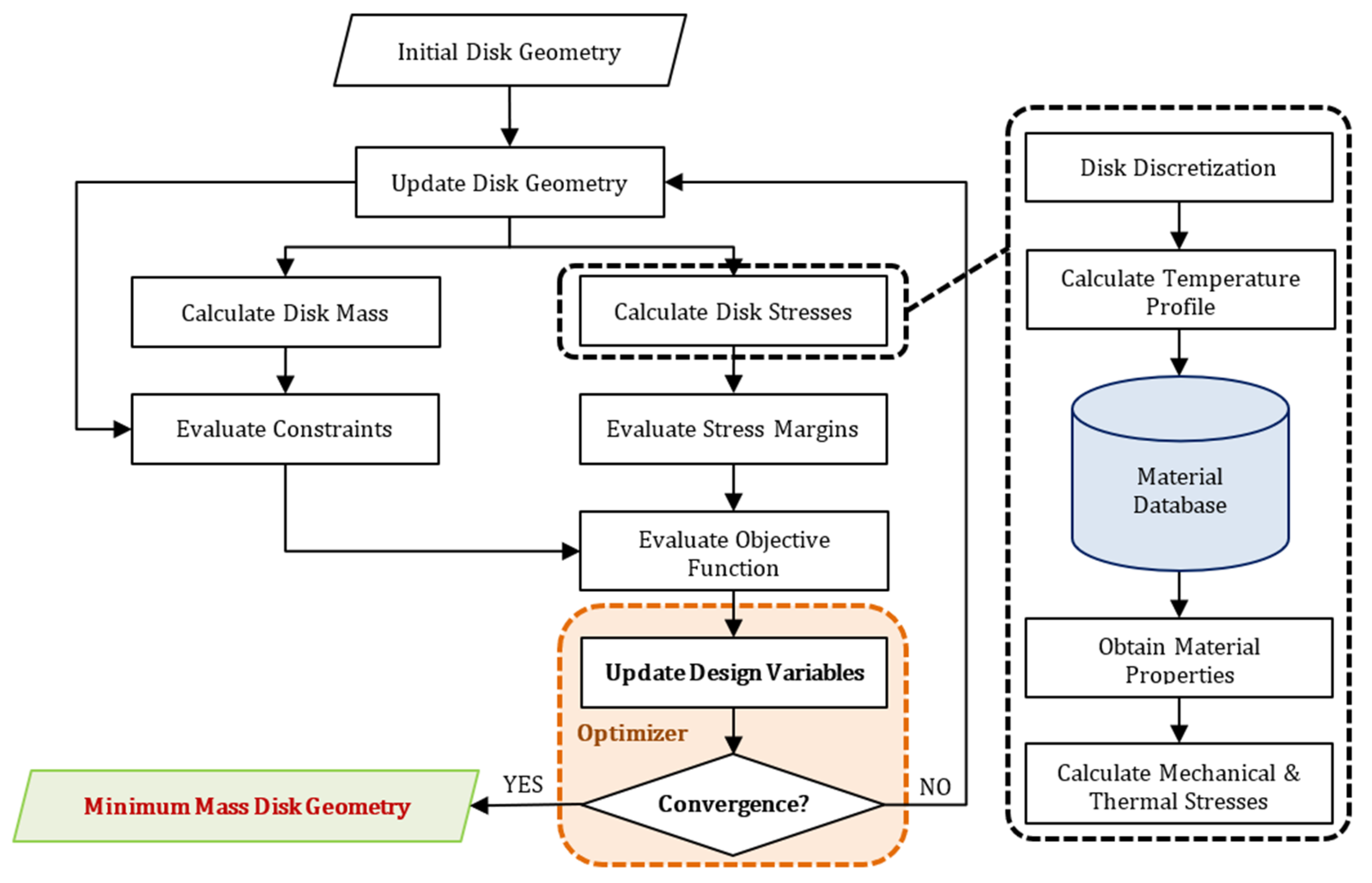
In the present paper, the development of a method and its materialization into a tool for the preliminary design of turbomachinery disks is described, called Rotating Disk Optimizer (RDO). RDO was built and integrated into the framework for the preliminary design and assessment of novel aero-engines that the team of authors has been building in recent years [14,15,16,17]. The framework has been developing in PROOSIS [18], an object-oriented coding environment for modeling and simulating gas turbine engines, which allows consistent modeling, easy code maintainability, and transparent integration of different design modules under the same, user-friendly software environment. Currently, the framework also includes modules for multi-point (steady-state) design and performance prediction, aerodynamic design and geometry estimation, weight calculations, off-design simulations, mission analysis and emissions, control system design, and transient performance prediction.
RDO formulates the disk design as a constrained optimization problem and exhibits a number of original features. Compared to other tools in which the disk design is formulated as a constrained weight minimization (e.g., [2,5,8,9,10,11,12,13]), in RDO the optimal disk geometry in terms of minimum weight is obtained by maximizing appropriately defined stress margins. Among the other publicly available approaches, the only one that offers this design option is GasTurb Details 5 [9], but no information about its formulation or efficiency is publicly available. An originality of RDO is that it introduces a number of computationally efficient approaches for the estimation of the developed stresses. For example, it incorporates a more accurate temperature model for the correct estimation of the thermal stresses compared to other tools suitable for preliminary design (e.g., [2,5,8,9,13]). Finally, the tool capabilities are demonstrated through appropriate validation and optimization test cases. For the latter, the NASA/GE E3 HPC [19,20] disks will serve as a demonstration for the tool’s functionality as far as the required baseline geometries are concerned.

2. RDO Workflow

The RDO workflow is depicted in Figure 1. A very simple workflow is employed, in which an optimizer updates the design variables so that a disk geometry is produced with the minimum weight while the problem constraints are fulfilled. For obtaining the disk mass and the necessary material properties (density, elastic modulus, Poisson’s ratio, etc.) in every optimization cycle, a database of engineering materials commonly used in gas turbine applications was developed in PROOSIS and integrated into RDO (see Appendix A). The mathematical formulations and computational approach used are described in the following sections.

3. Disk Geometry Modeling and Weight Estimation

In most gas turbine engines, the geometry of the disks can be classified into one of the following three basic types [8]: ring, web, and hyperbolic. Disks with continuous slope sections have also been proposed and studied in the open literature [12], but they are currently not modeled in RDO.
Each disk shape is divided into two portions: the live disk and the dead weight disk [9]. The rotor blades and blade attachment constitute the dead mass that produces the majority of the pull stress exerted on the rim of the live disk. The blade and attachment dimensions (and thus, weights) and the required loads (rotational speed, temperatures, and pressures) are produced by the aerothermodynamic design and are then fed into RDO, which conducts the design of the live disk geometry. The live disk shape is defined by six radial stations or, equivalently, by five segments, characterized by the values of a radius ( R ) and a thickness ( t ). Figure 2 illustrates diagrammatically the meridional view and the relevant nomenclature of the disk shapes considered in RDO.
For each of the five disk segments ( k = 1 , 2 , 3 , 4 , 5 ) seen in Figure 2, the thickness variation with radius is described by [12]:
t = t i + t o t i ( R o R i ) d s f ( r R i ) d s f
The subscripts i and o denote the inner and outer station of a disk segment, and d s f > 0 is a disk shape factor that can have different values in different disk segments. For d s f = 1 , a linear thickness variation is defined, while values of d s f 1 give the flexibility to define more complex thickness distributions.
The thickness profile of Equation (1), which applies at each of the five disk segments, leads to the following formula for calculating the disk total weight. Note that this expression can be used for disks consisting of any number of segments.
W = 2 π ρ k = 1 5 { t o t i ( R o R i ) d s f [ ( R o R i ) 2 + d s f 2 + d s f + R i ( R o R i ) 1 + d s f 1 + d s f ] + t i 2 ( R o 2 R i 2 ) } k

4. Disk Thermal Modeling and Validation

Temperature gradients in disks, especially in turbines, can be high enough to create significant thermal stresses. RDO employs a Disk-Simplified Thermal Model (D-STM) for calculating the temperature profile along the disk radius which, in turn, is needed for estimating the developed thermal stresses. This model is described below.

4.1. D-STM Formulation

Most disk design codes assume that the temperature varies according to a polynomial law (e.g., linearly in [9] or according to a 5th degree polynomial in [5]) or use empirical curves of proprietary nature (as, e.g., in [13]). Some tools (e.g., [8]) use more physics-based approaches to obtain the temperature profile along the disk span, which are nevertheless approximate. The latter come in the form of Fourier’s law for heat conduction, which, for constant material conductivity and for constant disk thickness, gives [21]:
T T r i m = 1 + T b o r e / T r i m 1 ln ( R b o r e / R r i m ) ln r R r i m
The above equation does not account for the disk thickness variation. However, as shown later, this omission leads to inaccurate physical solutions and results in the introduction of significant inaccuracy in the calculation of the disk mechanical stresses. In RDO, a more accurate model was introduced, although the calculation option given by Equation (3) is still available to the user.
For axisymmetric bodies of variable (axial) thickness, Fourier’s law for heat conduction assuming constant conductivity is expressed by a 2nd order differential equation, which, with the accompanying boundary conditions, reads [22]:
d d r ( A r d T d r ) = 0 , T = { T r i m , r = R r i m T b o r e , r = R b o r e
where A r = 2 π r t is the disk circumferential area at an arbitrary radius r . The above equation is discretized using a 2nd order accurate finite difference approach [23], which leads to a tridiagonal system of equations for obtaining the temperature profile T = T ( r ) . The latter is solved quickly using a tridiagonal system algorithm [24].
Equations (3) and (4) will be referred to as the “analytical” and “numerical” thermal models, respectively.

4.2. D-STM Validation

The numerical temperature model was validated against a 3D finite element analysis (FEA) model [25], which was itself validated against Equation (3) for a ring disk geometry assuming constant material conductivity. The example disk geometry and boundary conditions used for validating the numerical D-STM are shown in Figure 3.
The comparison between the analytical and numerical D-STMs with the FEA results is shown in Figure 4. The analytical D-STM, Equation (3), fails to capture the correct temperature trend altogether, where differences in temperature up to 21% can be observed. It will be shown later that this difference leads to significant errors in the estimation of the developed stresses. The numerical method, on the other hand, produces values practically identical to those of the FEA model, thus demonstrating its ability to capture the correct temperature profile when the disk thickness is accounted for.
It is worth noting that in a desktop PC (Windows 7 64-bit, Intel® CoreTM2 Duo CPU@3 GHz, 4GB RAM), both the analytical and numerical D-STMs required about 70 ms each on a grid of the same size (101 nodes were used after a mesh independence study). For comparison, the FEA model required ~2 min. In conclusion, the numerical D-STM offers far greater accuracy with a computational effort not greater than that of the analytical model, and significantly less than the FEA model.

5. Disk Stress Modeling and Validation

Disks are designed to withstand the mechanical stresses generated during engine operation. In RDO, the stresses that develop in the disk are established through the Disk-Simplified Stress Model (D-SSM) described below.

5.1. D-SSM Formulation

For disks of variable thickness, the stresses that develop due to blade, body, and thermal loads are estimated using the following plane stress equilibrium equation [26]:
d d r ( t r σ r ) t σ θ + t ρ r 2 ω 2 = 0
This equation is also used in other tools [5,8,9,10,11,12,13], and it is the simplest ordinary differential equation (ODE) for solving disk analysis problems when the disks are assumed to be axisymmetric bodies with small thicknesses compared to the radius.
For its solution, boundary conditions at the disk rim and bore are specified. In typical bladed disk applications, the disk rim is loaded due to the centrifugal forces developed by the disk dead weight. These forces are exerted on the disk rim as a tensile strength. On the other hand, the supporting structures connecting the disks to each other and to the shaft are flexible thin cylinders (or cones) that do not impose radial or tangential loads on the disk bore [5]. Hence, the boundary conditions required for solving Equation (5) are:
σ r = { σ r i m , r = R r i m 0 , r = R b o r e
These boundary conditions are the ones used for the test cases presented in this paper. However, the stress calculation code is general enough so that any combination of boundary conditions on the disk rim and bore can be specified.
For a given disk geometry and temperature field, Equations (5) and (6) constitute an ODE that involves two unknowns, namely σ r and σ θ . The equations are transformed into a system of equations with only one unknown, that is, the radial displacement u , using constitutive equations that relate stresses and strains. For isotropic materials, these are [26]:
σ r = E 1 ν 2 [ d u d r + ν u r ( 1 + ν ) α ( Τ Τ r e f ) ] , σ θ = E 1 ν 2 [ u r + ν d u d r ( 1 + ν ) α ( Τ Τ r e f ) ]
where T r e f = 20 °C. Note that the code has the possibility of calculating anisotropic materials too (similarly to [12]).
Substituting σ r   and σ θ from Equation (7) into Equations (5) and (6) gives a 1D, 2nd order, linear ODE for u = u ( r ) , which is solved numerically obtaining σ r = σ ( r )   and σ θ = σ ( r ) . In RDO, a 2nd order accurate finite volume scheme [12] is employed leading to a tridiagonal equations system that is solved using a tridiagonal system algorithm [24]. The von Mises stress is also calculated by:
σ v M = σ r 2 + σ θ 2 σ r σ θ

5.2. Formulation of Design and Burst Stress Margins

The stress criteria used for ensuring the structural integrity of the disk at every optimization cycle are given in the form of a design ( R D M ) and a burst (overspeed) ( R B M ) margin. These are expressed by the following equations:
R D M = σ v M , m a x / ( σ Y , m i n / S F Y )
R B M = ( σ ¯ θ / S F Τ ) / σ ¯ U T S
where R D M 1 and R B M 1 must hold for structural integrity. In the above, σ Y and σ U T S are the material yield strength and ultimate tensile strength (UTS), respectively, and S F Y 1.0 and S F T 1.0 are safety factors. A typical value for S F Y is 1.1 [5], but greater values could be adopted to compensate for inaccuracies in the stress estimations. On the other hand, S F T = 0.9 [5], but lower values could be adopted (e.g., S F T = 0.47 in [8]). S F Y and S F T are user-defined in RDO. Finally, the burst margin is usually evaluated at +120% or greater disk speeds [5,9], but the overspeed factor is a user input in RDO.

5.3. D-SSM Validation

D-SSM was validated against the results obtained by a higher-fidelity (3D) FEA software [25], which was itself validated against the analytical stress solution obtained for constant thickness (ring)-type disks with zero rim and bore boundary conditions [26].
For the validation, the example geometry and temperature boundary conditions shown in Figure 3 were used (material: Inconel-718). The hyperbolic-type disk illustrated in Figure 3 rotates at 3750 rpm (~393 rad/s), while the blade and attachment weights exert a boundary loading equal to 66.8 MPa at the disk rim. The temperature variation along the disk radius is obtained using the numerical D-STM. Finally, 141 nodes were used for radially discretizing the disk geometry (selected after a mesh independence study).
The comparison with the FEA results shown in Figure 5, show excellent agreement between the D-SSM and FEA models. D-SSM can thus successfully reproduce the stress trends developed in disks without the need of costly FEA calculations (~140 ms and ~3 min, respectively, in a workstation with Windows 7 64-bit, Intel® CoreTM2 Duo CPU@3 GHz, 4GB RAM).

5.4. Stress Calculations Including Lower Accuracy Heat Transfer Effects

For the sake of demonstrating the outcome of using lower accuracy heat transfer effects, the above calculation was repeated again, but this time the temperature profile was obtained using the analytical D-STM model. The results are shown in Figure 6.
From Figure 6, significant discrepancies between the D-SSM and FEA models are observed when heat transfer effects of lower accuracy are employed. The model fails to reproduce both the stress trends and magnitudes altogether. There are disk regions where even the stress signs are wrong, while maximum differences up to 200 MPa can be observed for the von Mises stress. Note that similar differences are observed when a linear variation for temperature is assumed (similarly to [9]).
It was shown in Section 4.2 that not considering the disk thickness variation leads to incorrect temperature fields. This discrepancy results in inaccurate stress trends, which, in turn, could lead to inaccurate disk designs, thus compromising the correct assessment of an engine’s potential. Therefore, employment of an accurate thermal model is important and, as we saw, this can be accomplished without increasing the computational effort.

6. Formulating the Optimization Problem

To avoid local optima and numerical instabilities, some researchers have resorted to evolutionary strategies for optimizing the disk geometry (e.g., in [12]). Such methods require prohibitive calculation times if an engine comprising several disks is to be optimized. In developing RDO, the Nelder-Mead SIMPLEX [27], direct-search, minimization algorithm was used. It was chosen because (1) it does not need any information about 1st- and 2nd-order derivatives, (2) it can handle non-continuous and non-smooth functions, (3) it requires very few function evaluations per iteration, and (4) it can produce satisfactory results very quickly, among other reasons [28]. Additionally, it is available in PROOSIS as a built-in and validated function.

6.1. Selection and Limits of Design Variables

For the design of a disk, the disk radii and thicknesses are selected as design variables. The values of these variables are updated in every optimization cycle, until a disk geometry is produced that has the minimum weight while not violating the imposed constraints. As described in Section 3, the disk shapes are described by six sets of radius and thickness values. For ensuring numerical stability and speed of execution, however, the minimum number of R ’s and t ’s should be selected as design variables while the remaining are fixed and correlated to them.
For all disk types, the thickness and radius at the disk rim are imposed by the dimensions of the rotor and its attachment ( R 6 = R r i m and t 6 = t r i m ), which are obtained by the aerothermodynamic design that precedes the mechanical design. For ring disks (Figure 2b), the thickness is radially constant and, therefore, the only variable required for defining the disk geometry is the bore radius ( R 1 = R b o r e ).
For web disks, t 1 = t 2 , t 3 = t 4 , and t 5 = t 6 (see Figure 2c), while the radii at stations 2 and 3 and those at stations 4 and 5 can be interrelated through a fixed angle assumption (e.g., see [3,9,13]):
R 3 = R 2 + t 2 t 3 2 tan β 23 , R 4 = R 5 t 5 t 4 2 tan β 45
where β 23 and β 45 are angles with default values equal to 36° [13].
For hyperbolic disks (Figure 2d), one additional equation can be used to interrelate the thicknesses at stations 3 and 4 since in hyperbolic disks t 3 t 4 :
t 3 = 1 3 ( t 2 + t 4 )
Therefore, the remaining radii and thicknesses form the design variables used in RDO for the optimization of each disk shape. These are summarized in Table 1.
Finally, the default min/max values used in RDO for the design variables are given in Table 2. These were obtained by digitizing publicly available 2D cutaways of commercially operational turbofan engines.

6.2. Objective Function and Constraints

6.2.1. Objective Function Formulation

In preliminary disk design, weight minimization is equivalent to maximizing the developed stresses [10]. Indicative figures for the maximum stresses developed in a disk are the design and burst margins defined in Equations (9) and (10). In RDO, the objective function is formulated as:
F O B J = [ max ( R D M , R B M ) 1 ] 2
where we seek to minimize F O B J or, in other words, to maximize whichever between R D M or R B M is larger, such that R D M 1 and R B M 1 . The minimization is subjected to a number of geometry constraints.
Maximizing the disk stresses instead of directly minimizing the disk weight was opted since it leads to minimum weight, but the mathematical problem formed has some advantages in terms of the minimization procedure. For producing acceptable disk designs, the minimization of the disk weight should be subjected to a number of geometry and stress constraints. For a robust and converging optimization procedure, the initial disk design should fall into the feasible solutions area when using, e.g., gradient-based or search optimization techniques. Initializing the disk dimensions alone, although it may be performed in a consistent manner, cannot always ensure the fulfillment of both Equations (9) and (10) if they are used as constraints. In other words, the initial disk geometry is not, by default, a feasible solution and, therefore, it cannot be used as a suitable starting point for a gradient-based or direct-search optimization technique.
On the other hand, formulating the minimization problem in the form of Equation (13) leaves as only constraints to be fulfilled by both the initial and optimized disk geometries the constraints related to the disk dimensions alone. In RDO, the initial and optimal disk geometries are produced in such a way that they always respect the min/max values of Table 2 and Equations (11) and (12) which, in turn, lead to reasonable disk shapes. This was tested by the authors during the formulation, development, and verification of RDO. It was concluded that formulating the minimization problem in the form of Equation (13) was more robust than directly minimizing the disk weight when using direct-search methods.

6.2.2. Constraints Formulation

In RDO, constraints are formulated as upper-bounded inequalities ( F C N S ε C N S ). Whenever a constraint is violated ( F C N S ε C N S ), the objective function is penalized by adding to it a penalty value ( F O B J + F P N L ).
In RDO, the design variables should respect the min/max boundaries shown in Table 2. For obtaining reasonable geometries for web and hyperbolic disks, R 4 > R 3 should also hold, while for hyperbolic disks, an additional constraint is that t 4 < t 3 .

7. Application Test Cases

RDO’s capabilities are demonstrated on optimization test cases for ring-, web-, and hyperbolic-type disks. For this reason, the 1st, 2nd, and 3rd stage disks of the NASA/GE E3 HPC were considered as far as the required baseline geometries, since they approximate disks of ring-, hyperbolic-, and web-shape, respectively. The baseline geometries and calculation inputs for the disks of the NASA/GE E3 HPC are given in Appendix B. The disk overspeed factor for evaluating the burst margin was set at 120%. The safety factors were set equal to S F Y = 1.1 and S F T = 0.9 . Finally, no heat transfer effects were considered and the temperature was set constant along the disk and equal to that at the disk rim.
According to [5], the NASA/GE E3 HPC disks were designed but not optimized for minimum weight. Therefore, to first assess how much more the disk masses can be reduced compared to the baseline disks, Equations (11) and (12) are “switched-off” during the optimization process and the respective dimensions are kept constant and equal to those of the baseline disks: ( R 3 ,   R 4 ,   t 3 ) = ( 140.1 ,   169.9 ,   15.3 ) mm for the 2nd stage (hyperbolic) disk, and ( R 3 ,   R 4 ) = ( 153.6 ,   198.6 ) mm for the 3rd stage (web) disk. That is, only the dimensions directly varied by the design variables are changed during the optimization. The results of the optimization are shown in Table 3.
The weight reduction achieved by RDO is significant for all three stages, ranging from 9.3% (2nd stage disk) to 39.1% (1st stage disk). In all cases, the disk weight minimization is accomplished by maximizing the burst margin ( R B M ) with a simultaneous increase in the design margin ( R D M ). For all three disks, the optimizer tends to minimize the disk weight by increasing R 1 as much as possible (i.e., has a greater relative change compared to the other design variables).
The convergence history for all three cases is shown in Figure 7, where the logarithm (base 10) of F O B J (left diagram) and the values of W (right diagram) are plotted against the optimization cycle. The optimization of the 1st stage requires less than one-third of the number of cycles required for the 2nd and 3rd stage disks (one design variable compared to five). For all optimization cases, the convergence is deep ( F O B J < 10 12 ).
Figure 8 illustrates the tangential stress distributions ( σ θ / 0.9 ) for the baseline and optimized disk geometries at 100% and 120% design speed for the 1st and 3rd stage disks. Note that the respective trends for the 2nd stage disk were similar to those of the 3rd stage disk and were omitted for brevity. This figure demonstrates the shift of the stress curve ( σ θ / 0.9 ) at 120% of design speed towards the UTS line for meeting the R B M criterion and the maximization of the disk stress ( R B M = 1.0 ). For all optimized disks, the tangential stress at 120% of design speed (blue dashed curve) has both greater and lower values than the respective UTS limit. This is because, according to Equation (10), R B M is formulated considering the average values of σ θ and σ U T S . Therefore, the optimizer updates the disk geometry until the σ θ curve is shifted to be half above-half below the UTS line. We also observed that the tangential stress at 120% of design speed (black dashed curve) for the 3rd stage baseline disk is greater than σ U T S along the inner rim and inner shoulder sections of the disk, contrary to the 1st stage baseline disk for which the respective curve is well below the UTS limit. Therefore, for the 1st stage disk, there is more room for meeting the R B M criterion than that required for the optimization of the 3rd (and 2nd) stage disk(s). Hence, greater weight reduction is achieved by RDO for the 1st stage disk compared to that for the 3rd (and 2nd) stage disk(s).
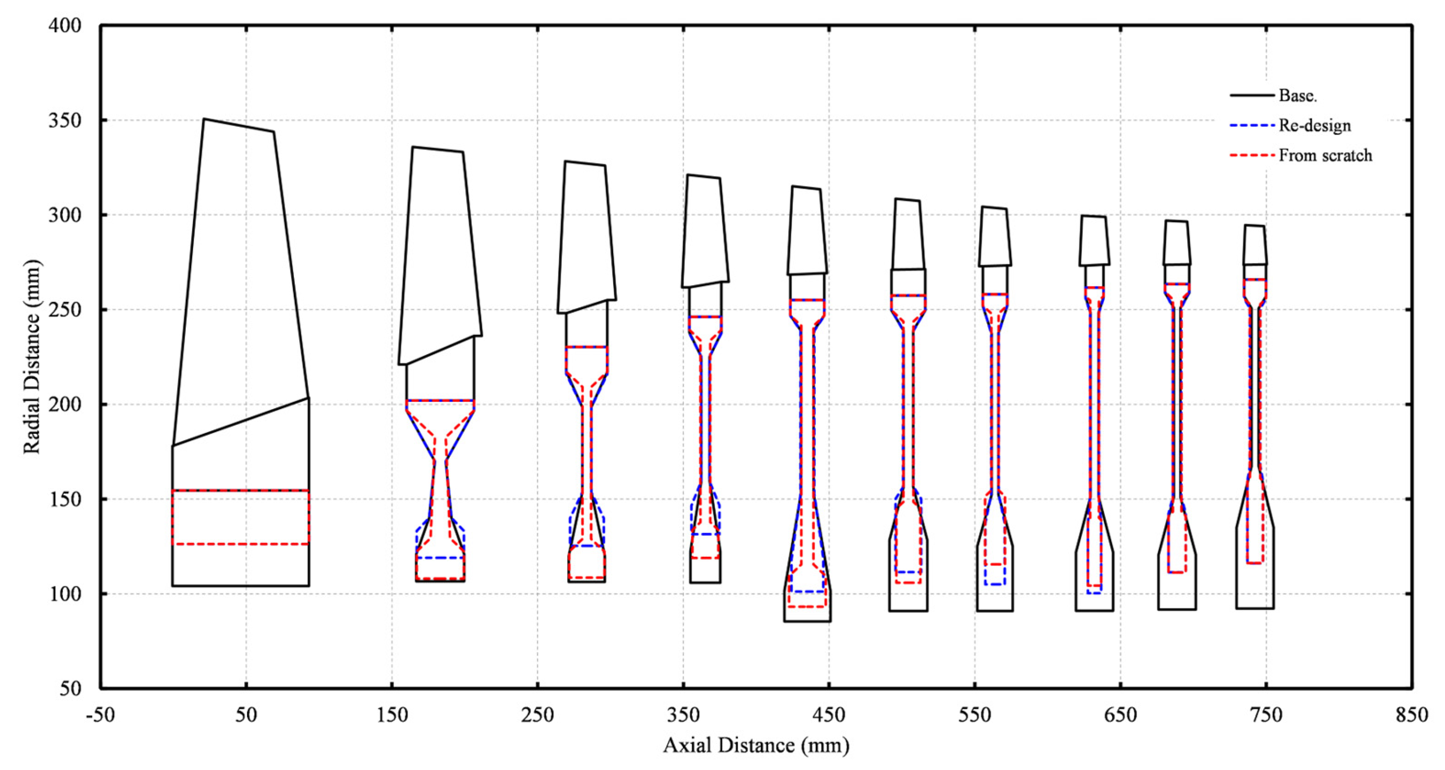
Next, the optimization of all ten (10) stage disks of the NASA/GE E3 HPC is conducted following two approaches: the re-design approach described above, and an approach in which Equations (11) and (12) are “switched-on” during the optimization, i.e., the disks are designed “from scratch”. The results of the two optimization approaches are presented in Table 4.
It is observed that the “from scratch” design achieves a greater overall weight reduction than the “re-design” (26.2% compared to 21.3%). Note, however, that both design approaches obtained the same weight reduction for the 1st stage disk (ring-type) since Equations (11) and (12) are not applicable for the design of ring-type disks and, therefore, the two design approaches are essentially the same. Figure 9 shows the meridional view of the compressor after the two designs. Regarding the time required for optimizing ten disks twice, it was less than 5 s in a desktop PC (Windows 7 64-bit, Intel® CoreTM2 Duo CPU@3 GHz, 4GB RAM).
Finally, the “from scratch” design is repeated, but this time heat transfer effects are accounted for by solving the numerical D-STM. For this calculation, the temperature at the bore of the disks was considered constant and equal to 20 °C (room temperature) across the compressor. The meridional view of the compressor after the new design is shown in Figure 10. The overall weight reduction is now 16.7% (compared to 26.2% without heat transfer effects). The weight reduction is smaller since more material is required to compensate for the increased stresses.

8. Integration of RDO into the Platform for the Preliminary Design of Aero-Engines

As shown above, RDO can produce fast and robust disk designs for multistage machines. Figure 11 illustrates the integration of RDO into the platform for the multidisciplinary preliminary design of aero-engines that the team of authors has been developing [14,15,16,17]. The geometry and weights of the gas-path, rotational speeds, and loads (temperatures and pressures) are produced by the aerothermodynamic design of the compressor or turbine components. This information is fed into RDO, which produces the dimensions of the discs required to hold the corresponding blading. The produced spool weights and inertias are then fed into the aircraft mission and transient analysis modules for assessing the overall flight performance. Finally, the disc geometry determination also contributes in the visualization of the engine gas-path.

9. Discussion

The main advantage of the presented formulation is that it allows to define initial disk geometries that lie in the feasible solutions section of the design space, since the only constraints that the initial disk geometry must fulfil are related to the dimensions of the disk and not the stress levels. This, in turn, allows search techniques to be used, which are faster than evolutionary techniques, thus enabling the robust design of multistage machines within acceptable times. The test cases presented showed that the design of the disks of a ten-stage compressor required about 5 s in a home desktop PC to design each disk twice!
For estimating the stress levels in a disk, some design tools use semi-analytical models of rather poor accuracy, while other tools use more accurate 1D ODEs that are solved numerically (see Introduction). In either case, all codes estimate the developed thermal stresses by assuming simplified models for the temperature radial profile. In this paper, a more accurate temperature model was proposed and integrated into RDO, which considers the variation of the disk thickness. It was shown that not including the thickness variation or using simple polynomial laws to establish the temperature profile leads to inaccurate results regarding the developed stress levels. This problem is expected to be more prevalent in hot-end components of gas turbines in which there are significant temperature gradients and, thus, the correct modeling of thermal stresses is essential. The thermal model employed in RDO essentially requires the same computational time compared to analytical approaches, but offers significantly higher accuracy.

10. Conclusions

A tool for the preliminary, optimal design of turbomachinery disks (RDO) was presented. It formulates the disk weight minimization problem as an equivalent, constrained maximization problem of the stresses developed in the disk. This is accomplished by appropriately defined design and overspeed (burst) margins that express the level of the developed radial and tangential stresses. This formulation and its efficiency with regard to engine optimization problems are presented in the open literature for the first time.
In this study, it was also shown that the RDO stress models can accurately model and predict the stresses developed in disks, thus leading to reasonable designs from the very start of the design process. In fact, this is achieved without the need for FEA tools, which are computationally costly, difficult to integrate into preliminary design platforms, and require a certain level of expertise in setting-up the model and the calculation sequence.
Finally, real-case optimization problems demonstrated that the proposed formulation leads to robust, fast, and deep-converging optimization problems and, therefore, it can be integrated in platforms used for the preliminary design of gas turbine engines.

Author Contributions

Conceptualization, I.K., N.A. and A.A.; methodology, I.K. and N.A.; software, I.K.; validation, I.K.; formal analysis, I.K.; investigation, I.K.; data curation, I.K. and N.A.; writing—original draft preparation, I.K.; writing—review and editing, I.K., N.A., A.A. and K.M.; visualization, I.K.; supervision, N.A., A.A. and K.M. All authors have read and agreed to the published version of the manuscript.

Funding

This project has received funding from the Clean Sky 2 Joint Undertaking (JU) under grant agreement No 886840. The JU receives support from the European Union’s Horizon 2020 Research and Innovation Programme and Clean Sky 2 JU members other than the Union.

Data Availability Statement

The data presented in this study are available on request from the corresponding authors.

Acknowledgments

The authors would like to deeply thank Agapi Bakogianni for obtaining and providing the FEA results used to validate RDO’s stress models. They would also like to thank Konstantinos Ntonas for his expertise with FEA tools and his advice for correctly setting up the FEA models and post-processing the simulation results.

Conflicts of Interest

The authors declare no conflict of interest.

Nomenclature

Abbreviations
1/2/3D1-/2-/3-DimensionalLCFLow Cycle Fatigue
D-SSMDisk-Simplified Stress ModelNASANational Aeronautics and Space Administration
D-STMDisk-Simplified Thermal ModelPROOSISPropulsion Object Oriented SImulation Software
FEAFinite Element AnalysisRDORotating Disk Optimizer
GEGeneral ElectricUTSUltimate Tensile Strength
HPCHigh-Pressure CompressorXMLExtensible Markup Language
Symbols
A Area (m2) u Radial displacement (m)
d s f Disk shape factor (-) V Material volume (m3)
E Modulus of elasticity (Pa) W Weight (kg)
F Functional/Function X Generic/dummy variable
k Counter/Index α Coefficient of thermal expansion (m/m/°C)
r Radial coordinate (m) β Angle (°)
R Radius (m) ε Threshold/Tolerance
R B M Burst margin (-) ν Poisson’s ratio (-)
R D M Design margin (-) ρ Material density (kg/m3)
S F Safety factor (-) σ Normal stress (Pa)
t Thickness (m) ω Rotational speed (rad/s)
T Temperature (K)
Subscripts
1,2,3,4,5,6Disk station numbering r Radial component
b o r e Disk bore r e f Reference condition
C N S Constraint function r i m Disk rim
i / o Inner/Outer U T S Ultimate tensile strength
m i n / m a x Minimum/Maximum v M von Mises stress
O B J Objective function Υ Yield strength
P N L Penalty function θ Tangential component

Appendix A. Materials in RDO Database

A database of structural materials is essential for performing mechanical design. A database of materials commonly used in gas turbine applications was thus developed in PROOSIS, based on information extracted from wider material databases and vendor datasheets. The materials included are shown in Table A1. For each material, the density, modulus of elasticity, yield strength at 0.2% strain, UTS, Poisson’s ratio, and coefficient of thermal expansion are available in dedicated XML files. The mechanical properties are stored in the XML files in terms of temperature, thus allowing accurate calculations in the presence of accountable temperature variations.
Table A1. Database of available materials in RDO.
A-286Haynes-282Inconel-706ΒKevlar-49Rene-N5
AM-350Incoloy-800Inconel-718Mar-M-247Ti-6Al-4V
Aluminum-2050Incoloy-907Inconel-738N-155Ti-8-1-1
Gr. Ascoloy-418Incoloy-925Inconel-740Nimonic-105Udimet-720
Hastelloy-SInconel-601Inconel-783Rene-41Waspaloy
Haynes-188Inconel-706AKevlar-149Rene-N4

Appendix B. Calculation Inputs for the NASA/GE E3 HPC Disks

The NASA/GE E3 HPC used as a baseline test case in the present paper is a high-speed, high-aerodynamic loading, ten-stage compressor designed with an overall pressure ratio of 25 and a rotational speed of 12,416.5 rpm [19]. Table A2 summarizes necessary information about the disks as extracted by [19,20], while a 2D cutaway of the compressor is depicted for completeness in Figure A1.
Table A2. Information for the NASA/GE E3 HPC disks [19,20].
Stage:12345678910
Disk typeRingHyper.WebWebWebWebWebWebWebWeb
MaterialTi811Ti6Al4VTi6Al4VTi6Al4VTi6Al4VInco.718Inco.718Inco.718Inco.718Inco.718
R 1 (mm)104.1106.6106.3105.985.591.091.091.191.792.2
R 2 (mm) 121.0120.1122.4101.7128.3125.1122.1120.7135.0
R 3 (mm) 140.1153.6159.5152.7156.4152.3151.2151.0167.3
R 4 (mm) 169.9198.6225.1238.9239.0237.6248.4250.9250.7
R 5 (mm) 196.7217.1237.9247.0249.5251.8256.5258.8257.0
R 6 (mm)154.6202.0230.3246.2255.0257.4258.1261.6263.5265.9
t 1 (mm) 32.924.720.631.725.924.325.525.525.5
t 2 (mm) 32.924.720.631.725.924.325.525.525.5
t 3 (mm) 15.36.25.88.76.74.65.44.65.0
t 4 (mm) 7.56.25.88.76.74.65.44.65.0
t 5 (mm) 46.228.122.023.323.316.712.216.715.0
t 6 (mm)93.746.228.122.023.323.316.712.216.715.0
T r i m (K)323.2379.9433.2486.4540.3595.9646.0697.2751.1804.8
σ r i m (MPa)89.770.661.650.259.365.470.858.548.539.2
Shaft radius (cm)6.95
Figure A1. 2D cutaway of the NASA/GE E3 HPC [20].
Aerospace 10 00460 g0a1

References

  1. Mattingly, J.D.; Heiser, W.H.; Pratt, D.T. Aircraft Engine Design, 2nd ed.; AIAA Education Series: Renton, VA, USA, 2002; ISBN 1-56347-538-3. [Google Scholar]
  2. Becker, R.-G.; Reitenbach, S.; Klein, C.; Otten, T.; Nauroz, M.; Siggel, M. An Integrated Method for Propulsion System Conceptual Design. In Proceedings of the ASME Turbo Expo 2015, Montreal, QC, Canada, 15–19 June 2015; p. GT2015-43251. [Google Scholar] [CrossRef]
  3. Schaber, R.; Salpingidou, C.; Klingels, H. From Interdisciplinary Propulsion System Parameter Studies to Initial Module Design-An Integrated Approach for Conceptual Design. In Proceedings of the 24th ISABE Conference, Canberra, Australia, 22–27 September 2019; p. ISABE-2019-24040. [Google Scholar]
  4. Salpingidou, C.; Schaber, R.; Klingels, H.; Geiger, P. Mechanical Design in an Interdisciplinary Predesign Tool. In Proceedings of the ASME Turbo Expo 2020, Virtual, Online, 21–25 September 2020; p. GT2020-14633. [Google Scholar] [CrossRef]
  5. Armand, S.C. Structural Optimization Methodology for Rotating Disks of Aircraft Engines; NASA, TM 4693; NASA Lewis Research Center: Cleveland, OH, USA, 1995. [Google Scholar]
  6. Kurzke, J.; Halliwell, I. Propulsion and Power: An Exploration of Gas Turbine Performance Modeling, 1st ed.; Springer: Cham, Switzerland, 2018; ISBN 978-3-319-75977-7. [Google Scholar]
  7. Lim, J.S.; Chung, M.K. Design Point Optimization of an Axial-Flow Compressor Stage. Int. J. Heat Fluid Flow 1989, 10, 48–58. [Google Scholar] [CrossRef]
  8. Tong, M.T.; Halliwell, I.; Ghosn, L.J. A Computer Code for Gas Turbine Engine Weight and Disk Life Estimation. J. Eng. Gas Turbines Power 2004, 126, 265–270. [Google Scholar] [CrossRef]
  9. Kurzke, J. GasTurb Details 5: An Utility for GasTurb 11; GasTurb Details 5 Software Manual; GasTurb GmbH: Aachen, Germany, 2007. [Google Scholar]
  10. Gutzwiller, D.P.; Turner, M.G.; Downing, M.J. Educational Software for Blade and Disk Design. In Proceedings of the ASME Turbo Expo 2009, Orlando, FL, USA, 8–12 June 2009; p. GT2009-59692. [Google Scholar] [CrossRef]
  11. Gutzwiller, D.P.; Turner, M.G. Low Fidelity Turbomachinery Disk Design Studies. In Proceedings of the ASME Turbo Expo 2010, Glasgow, UK, 14–18 June 2010; p. GT2010-22733. [Google Scholar] [CrossRef]
  12. Gutzwiller, D.P.; Turner, M.G. Rapid Low Fidelity Turbomachinery Disk Optimization. J. Adv. Eng. Software 2010, 41, 779–791. [Google Scholar] [CrossRef]
  13. Lolis, P. Development of a Preliminary Weight Estimation Method for Advanced Turbofan Engines. Ph.D. Thesis, Cranfield University, Bedford, UK, 2014. [Google Scholar]
  14. Alexiou, A.; Aretakis, N.; Roumeliotis, I.; Kolias, I.; Mathioudakis, K. Performance Modelling of an Ultra-High Bypass Ratio Geared Turbofan. In Proceedings of the 23rd ISABE Conference, Manchester, UK, 3–8 September 2017; p. ISABE-2017-22512. [Google Scholar]
  15. Kolias, I.; Alexiou, A.; Aretakis, N.; Mathioudakis, K. Direct Integration of Axial Turbomachinery Preliminary Aerodynamic Design Calculations in Engine Performance Component Models. In Proceedings of the ASME Turbo Expo 2018, Oslo, Norway, 11–15 June 2018; p. GT2018-76494. [Google Scholar] [CrossRef]
  16. Kolias, I.; Alexiou, A.; Aretakis, N.; Mathioudakis, K. Axial Compressor Mean-Line Analysis: Chocking Modelling and Fully-Coupled Integration in Engine Performance Simulations. Int. J. Turbomach. Propuls. Power 2021, 6, 4. [Google Scholar] [CrossRef]
  17. Alexiou, A.; Aretakis, N.; Kolias, I.; Mathioudakis, K. Novel Aero-Engine Multi-Disciplinary Preliminary Design Optimization Framework Accounting for Dynamic System Operation and Aircraft Mission Performance. J. Aerosp. 2021, 8, 49. [Google Scholar] [CrossRef]
  18. EcosimPro|PROOSIS Modelling and Simulation Software. Available online: http://www.proosis.com/ (accessed on 9 February 2023).
  19. Holloway, P.R.; Knight, G.L.; Koch, C.C.; Shaffer, S.J. Energy Efficient Engine: High Pressure Compressor Detail Design Report; NASA, CR-165558; NASA Lewis Research Center: Cleveland, OH, USA, 1982. [Google Scholar]
  20. Davis, D.Y.; Stearns, E.M. Energy Efficient Engine: Flight Propulsion System Final Design and Analysis; NASA, CR-168219; NASA Lewis Research Center: Cleveland, OH, USA, 1985. [Google Scholar]
  21. Holman, J.P. Heat Transfer, 10th ed.; McGraw-Hill Inc.: New York, NY, USA, 2010; ISBN 978-0-07-352936-3. [Google Scholar]
  22. Cengel, Y.A.; Ghajar, A.J. Heat and Mass Transfer: Fundamentals and Applications, 5th ed.; McGraw-Hill Inc.: Singapore, 2015; ISBN 978-0-07-339818-1. [Google Scholar]
  23. Tannehill, J.C.; Anderson, D.A.; Pletcher, R.H. Computational Fluid mechanics and Heat Transfer, 2nd ed.; Taylor and Francis Inc.: Washington, DC, USA, 1997; ISBN 1-56032-046-X. [Google Scholar]
  24. Press, W.H.; Teukolsky, S.A.; Vetterling, W.T.; Flannery, B.P. Numerical Recipes: The Art of Scientific Computing, 3rd ed.; Cambridge University Press: Cambridge, UK, 2007; ISBN 13 978-0-521-88068-8. [Google Scholar]
  25. Ansys Mechanical Finite Element Analysis (FEA) Software for Structural Engineering. Available online: https://www.ansys.com/products/structures/ansys-mechanical (accessed on 9 February 2023).
  26. Ugural, A.C.; Fenster, S.K. Advanced Strength and Applied Elasticity, 4th ed.; Prentice Hall: Hoboken, NJ, USA, 2003; ISBN 0-13-047392-8. [Google Scholar]
  27. Nelder, J.A.; Mead, R. A Simplex Method for Function Minimization. Comput. J. 1965, 7, 308–313. [Google Scholar] [CrossRef]
  28. Nelder-Mead Algorithm. Available online: http://www.scholarpedia.org/article/Nelder-Mead_algorithm (accessed on 9 February 2023).
Figure 1. RDO workflow for obtaining disks of minimum weight.
Aerospace 10 00460 g001
Figure 2. Meridional view and nomenclature of the disks considered in RDO: (a) Disk/blade assembly defining the disk live and dead weights; (b) Ring disk; (c) Web disk; (d) Hyperbolic disk.
Aerospace 10 00460 g002
Figure 3. Example disk geometry and boundary conditions for validating the RDO stress models.
Aerospace 10 00460 g003
Figure 4. Temperature profile comparison between the FEA and the analytical/numerical D-STMs.
Aerospace 10 00460 g004
Figure 5. Comparison of the radial, tangential, and von Mises stresses between the FEA and the D–SSM including higher-accuracy heat transfer effects.
Aerospace 10 00460 g005
Figure 6. Comparison of the radial, tangential, and von Mises stresses between the FEA and the D– SSM including lower accuracy heat transfer effects.
Aerospace 10 00460 g006
Figure 7. Convergence history for the re–design of the NASA/GE E3 disks: (a) Objective function vs optimization cycle; (b) Weight vs optimization cycle.
Aerospace 10 00460 g007
Figure 8. Baseline and optimized tangential stress comparison for the NASA/GE E3 HPC: (a) 1st stage disk; (b) 3rd stage disk.
Aerospace 10 00460 g008
Figure 9. NASA/GE E3 HPC meridional view showing the baseline and optimized disk shapes for the re–design and “from scratch” design without heat transfer effects.
Aerospace 10 00460 g009
Figure 10. NASA/GE E3 HPC meridional view showing the baseline and optimized disk shapes for the “from scratch” design considering heat transfer effects.
Aerospace 10 00460 g010
Figure 11. RDO integration into the PROOSIS platform for the preliminary design of aero-engines [14,15,16,17].
Aerospace 10 00460 g011
Table 1. Design variables for optimizing different disk shapes.
Disk TypeNr. of Design VariablesDesign Variables
Ring1 R 1
Web5 R 1 , ( R 2 R 1 ) / t 6 , ( R 6 R 5 ) / t 6 , t 1 / t 6 , t 4 / t 6
Hyperbolic5 R 1 , ( R 2 R 1 ) / t 6 , ( R 6 R 5 ) / t 6 , t 1 / t 6 , t 4 / t 6
Table 2. Default min/max values for the design variables.
Design VariableMin. ValueMax. Value
CompressorTurbineCompressorTurbine
R 1 1.1 × shaft radius
( R 2 R 1 ) / t 6 0.30.23.03.0
( R 6 R 5 ) / t 6 0.10.10.70.5
t 1 / t 6 0.70.82.52.0
t 4 / t 6 0.10.5
Table 3. Re-design results for the NASA/GE E3 HPC 1st, 2nd, and 3rd stage disks.
Stage (Type)1 (Ring)2 (Hyperbolic)3 (Web)
QuantityBase.Opt.qDiff. 1Base.Opt.qDiff.Base.Opt.qDiff.
R 1 / shaft   radius (-)1.4981.818−21.3%1.5341.714−11.7%1.5301.803−17.9%
( R 2 R 1 ) / t 6 (-)N/AN/AN/A0.3120.305+2.0%0.4910.521−6.1%
( R 6 R 5 ) / t 6 (-)N/AN/AN/A0.1150.115−0.5%0.4700.510−8.5%
t 1 / t 6 (-)N/AN/AN/A0.7120.703+1.3%0.8790.826+6.1%
t 4 / t 6 (-)N/AN/AN/A0.1620.164−1.0%0.2210.223−1.1%
W (kg)16.810.2+39.1%9.78.8+9.3%8.57.7+10.0%
R B M (-)0.6311.000−58.5%0.8781.000−13.9%0.8471.000−18.1%
R D M (-)0.5970.863−44.6%0.8360.927−10.9%0.8250.954−15.6%
1 The relative difference from baseline is defined as: qDiff . = 100 × ( X Base . X Opt . ) / X Base . .
Table 4. Comparison of re-design and “from scratch” design for the NASA/GE E3 HPC disks.
Stage12345678910
Base. W (kg)16.89.78.57.411.118.814.614.714.117.4
Re-design W (kg)10.28.87.76.29.815.611.510.711.113.1
qDiff. (%) 139.19.310.016.012.316.921.226.921.224.4
Scratch design W (kg)10.27.86.86.08.614.810.410.210.612.9
qDiff. (%)39.119.620.618.922.421.629.130.724.725.6
1 The relative difference from baseline is defined as: qDiff . = 100 × ( X Base . X Opt . ) / X Base . .
Disclaimer/Publisher’s Note: The statements, opinions and data contained in all publications are solely those of the individual author(s) and contributor(s) and not of MDPI and/or the editor(s). MDPI and/or the editor(s) disclaim responsibility for any injury to people or property resulting from any ideas, methods, instructions or products referred to in the content.

