Abstract
Space exploration greatly facilitates the development of advanced propulsion systems. Extensive research has shown that hybrid rocket motors have bright prospects for use in variable-thrust propulsion systems. However, the variable-thrust precision control of a hybrid rocket motor with a high-mass fraction of aluminum has not been adequately explored. In this paper, we propose a closed-loop control system for a high-performance laboratory-scale hybrid rocket motor, and verify its performance through tests on a hybrid rocket motor containing 98% hydrogen peroxide and hydroxyl-terminated polybutadiene with 58% of an aluminum additive. The results show that, first, the average value of thrust in the stable sections in the three stages were 400.7 N, 599.1 N, and 400.1 N when the target values were 400 N, 600 N, and 400 N, respectively. Second, the average thrust was stable, and the control error of the average value was better than 0.5%. Third, the real-time error in thrust was controlled to within ± 20 N with a steady-state error smaller than 5%. These results indicate that the proposed closed-loop control strategy for hybrid rocket motors with a high-mass fraction of aluminum can maintain a constant thrust and smooth transitions in case of variable thrust.
1. Introduction
The use of hybrid rocket motors in a variety of fields has promoted research on effective and accurate motor control. They have received considerable attention in studies on space missions due to their safety, easily controlled thrust, on-demand restart capability, and low cost [1,2]. They also play a supporting role in missions involving space transportation [3,4], manned lunar landings [5,6], and Mars vehicles [7,8]. The control of hybrid rocket motors thus warrants further research, especially from the perspectives of their specific impulse performance and accuracy of thrust control.
Research on high-performance hybrid rocket motors has focused on their regression rate and specific impulse [9,10,11] as well as the disadvantages incurred by their poor mechanical strength [12,13,14]. Our team has added metals to fuels of hydroxyl-terminated polybutadiene (HTPB) to improve their performance. Adding 58% aluminum to HTPB-based fuels improves the specific impulse and regression rate [15,16], but large amounts of aluminum additives lead to nozzle ablation, uncertainty in regression rate, and the instability of combustion pressure [15,17,18] that directly yield unpredictable and unstable thrust and indirectly lead to debris emissions [5,19,20]. Therefore, we seek to compensate for nozzle ablation and oscillations in thrust by regulating the flow rate of the oxidizer from the perspective of the control system. In this way, we can ensure the stability of the thrust and improve the accuracy of thrust control during the operation of a high-performance hybrid rocket motor.
Thrust control has long been a vital and challenging issue in research on rocket motors. The thrust control of liquid rocket motors is mainly achieved by adjusting the flow rates of the oxidizer and the fuel. This is complicated because it requires simultaneously regulating the mass flow rates of both based on their mixing ratio [21,22]. Thrust control is realized in solid rocket motors by changing the area of the nozzle throat by using a pintle valve or secondary-flow injection [23,24]. Thrust control in hybrid rocket motors is achieved by adjusting the flow rate of the oxidizer by using a control valve [25]. This suggests that it is easy to control the thrust of hybrid rocket motors. A turndown ratio of 67:1 in the thrust was reported in one study by using an inexpensive off-the-shelf throttle valve in a hybrid rocket motor containing nitrous oxide and HTPB [26]. Closed-loop throttle control is easier to implement in a hybrid rocket motor due to the controllability of its thrust [27]. Past research has reported the closed-loop throttle control of a laboratory-scale hybrid rocket motor containing nitrous oxide and HTPB [28]. The results showed that closed-loop throttle control significantly reduced the mean run-to-run variations in thrust from ±9.1% to lower than ±3.9%. The variation in thrust was reduced to ±1.5% when the effects of erosion of the nozzle were considered [28]. A closed-loop thrust control scheme for a laboratory-scale paraffin wax/nitrous oxide hybrid rocket motor was implemented by using a low-cost ball valve as the controlling hardware. The results of the experiments showed that the motor remained throttled within ± 2.4% of the maximum thrust [29].
Adding 58% of an aluminum additive to HTPB can significantly improve the regression rate and specific impulse of the hybrid rocket motor [15]. However, oscillations in the thrust of the propellant containing an aluminum additive are severer than those in the propellant without an aluminum additive [30]. The pressure of the combustion chamber and thrust of hybrid rocket motors with a high mass fraction of aluminum are shown in Figure 1. Unstable combustion is generated with the addition of a large number of aluminum particles. Moreover, the attendant oscillations do not occur as the motor starts operating but instead emerge after a certain duration of its operation. As combustion proceeds, the oscillations in thrust gradually increase and the average thrust increasingly varies. Adding a large number of aluminum particles to the fuel can increase the regression rate and specific impulse of the motor, but leads to the new problem of wide fluctuations in thrust that limit its use. Moreover, few closed-loop control systems use linear regulating valves for a high-performance hybrid rocket motor with HTPB-based fuel with aluminum additives. To fill this gap in research, we propose a closed-loop control system for a high-performance hybrid motor in this study. We design a closed-loop throttle control strategy to ensure constant thrust in the range of operation of the motor and a smooth transition during variable thrust.
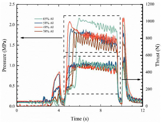
Figure 1.
Pressure in the combustion chamber and thrust of the hybrid rocket motor [30].
Based on the above considerations, the major objective of this study is to improve the applicability of the variable-thrust hybrid rocket motor with a high mass fraction of aluminum through a method of closed-loop control. We use the design of a segmented proportional–integral–derivative (PID) controller to control the average thrust and achieve a smooth transition in variable thrust. We verified the design through one hot firing test on a hybrid rocket motor containing 98% hydrogen peroxide and HTPB with 58% of an aluminum additive.
2. Control System
2.1. Incremental PID Control Algorithm
We use the variable-area cavitating venturi as an actuator in this study. The input to the actuator in each control cycle is the increase in the pintle of the valve. We use the incremental PID control algorithm to solve for this. The formula of recurrence for the incremental PID is obtained from the literature [18]:
The deviation in the control signal error(k) in the k-th control cycle is the difference between the set value yd(k) and the measured value y(k) in the current cycle.
The output of the k-th control cycle is the increment Δu(k), which is the difference between the total output of the current control cycle u(k) and the total output of the previous control cycle u(k − -1).
The increment Δu(k) can be obtained by combining Equation (1) with Equation (3):
where Δu(k) depends only on the control parameters (kp, ki, and kd) and deviations in the control signal (u(k), u(k − 1), and u(k − 2)). Therefore, incorrect movements of the control valve have a weak impact on the control system such that it maintains its stability.
2.2. Segmented PID Algorithm
Because the hybrid rocket engine considered in this study uses 98% hydrogen peroxide and HTPB fuel containing 58% Al as a propellant, the thrust signal oscillates severely, and deviations in the control signal error(k) are uncertain and random. To ensure the stability and accuracy of control of the thrust, we limit the calculated control parameters and the increment in control Δu(k) to within a narrow range such that the signal response of actual thrust is slow. When the set target thrust changes sharply, the deviation in the control signal error(k) is large within a short period, and a long response time is required to reach the target thrust in this case. We propose the segmented PID algorithm to appropriately balance the response time and the accuracy of control of the variations in thrust.
The idea underlying the segmented PID algorithm is as follows: When the actual thrust deviates significantly from the set thrust, large values of the control parameters (kp0, ki0, and kd0) are used. The output increment in control Δu(k) is thus larger and the thrust response is fast. When the deviation in thrust is reduced to within a certain range, small control parameters (kp1, ki1, and kd1) are chosen to avoid overshooting, and to ensure the stability and accuracy of the thrust response of the motor. The use of segmented control can simultaneously ensure the rapidity, accuracy, and stability of the thrust response of the motor. The implementation of the segmented PID algorithm consists of three steps. First, we set the threshold value ε > 0. Second, we select the control parameters. Larger control parameters (kp0, ki0, and kd0) are used when |error(k)| > ε, and smaller control parameters (kp1, ki1, and kd1) obtained through calculations are used when |error(k)| < ε. Finally, the segmented incremental PID control algorithm can be expressed as:
The above algorithm can ensure both the rapidity of transitions of the thrust and the accuracy of its steady states.
2.3. Quasi-Steady-State Assumptions
The object of control in this paper is a laboratory-sized hybrid rocket motor. Because many disturbing factors related to dynamic changes are in play during actual ignition tests of hybrid rocket motors, it is difficult to determine them one by one. For example, the hybrid rocket motor has different characteristics of thrust response to the flow rate of the oxidizer in different stages of its operation, where the diameter of the grain port and the area of combustion are variable. Therefore, we make quasi-steady-state assumptions regarding the hybrid rocket motor to simplify the object of control:
- The first half of the control cycle of the motor is dynamic and the flow rate is variable. The displacement of the pintle valve is fixed in the second half of the control cycle and the flow rate is constant.
- The dynamic characteristics of the motor during the first half of the control cycle are neglected.
- The motor reaches a quasi-steady state before the end of the second half of the control cycle.
- A quasi-steady state means that the motor reaches a steady state at the end of the control cycle, and its performance-related parameters satisfy the characteristic static equations.
The purpose of the quasi-steady-state assumptions is to simplify the equations of dynamic control into characteristic static equations of control, at the cost of waiting for half a control cycle so that the motor reaches a quasi-steady state. A certain opening of the valve corresponds to a certain flow rate in the characteristic static equations, and this corresponds to a certain thrust. There is no dynamic term in the relationship.
2.4. Components of the Control System
The object of control in this study is a laboratory-sized hybrid rocket motor and the control variable is the thrust of the motor. The measuring element for collecting actual thrust signals is an s-type compression force transducer. A variable-area cavitating venturi is used as the actuator, and a programmable logic controller (PLC) is the value of the set thrust-providing element.
A functional block diagram of the control system
is shown in Figure 2. The PLC serves as
the controller, provides the value of the target thrust, and implements the
segmented incremental PID algorithm. The output of the PLC is the control
increment Δu(k), which is a certain number of high-speed pulses.
The input signal to the servo motor driver consists of high-speed pulses and
the output is a PWM signal (pulse width modulation). The servo motor driver
actuates the servo motor to rotate at a certain angle depending on the number
of high-speed pulses. The servo motor converts rotational motion into linear
motion through couplings, ball screws, and other transmission devices to drive
the pintle of the variable-area cavitating venturi to move and change its
throttling area, where this changes the flow rate of the oxidizer. The hybrid
rocket motor accepts the oxidizer from the feed system of the propellant, and
generates thrust through combustion and expansion. The thrust of the motor is transferred
to the compression force transducer through the thrust test bench. The
compression force transducer converts the real-time thrust into an output
signal of 4–20 mA. This signal is subjected to low-pass filtering (100 Hz)
through an isolator to eliminate high-frequency interference from it. The
analog-to-digital (AD) conversion module converts the 4–20 mA analog signals
into digital signals in the range of 0–32000. The PLC then converts these
digital signals into real-time thrust values, and then differentiates the
latter from the set target thrust to obtain the deviation in control error(k)
in the current control cycle.

Figure 2.
Functional block diagram of the control system.
2.5. Flow Control Valve
The actuator of the control system is a flow control valve that indirectly regulates the thrust of the motor by adjusting the flow rate of the oxidizer. The flow control valve is vital in the control loop because its linearity and response characteristics significantly influence the accuracy and response time of the control system.
We used a variable-area cavitating venturi as the flow control valve due to its advantages of high linearity, fast response, and isolation from fluctuations in the downstream pressure. A schematic diagram of the variable-area cavitating venturi is shown in Figure 3.

Figure 3.
Schematic of variable-area cavitating venturi [31].
The variable-area cavitating venturi mainly consists of a servo motor, a transmission assembly, a pintle, and a venturi tube. The servo motor converts the rotational motion of the output shaft into the linear motion of the pintle through the transmission assembly, and the area of throttling changes with the linear motion of the pintle [32,33,34]. The relationship between the throttling area of the variable-area cavitating venturi and the pintle stroke is shown in Figure 4.
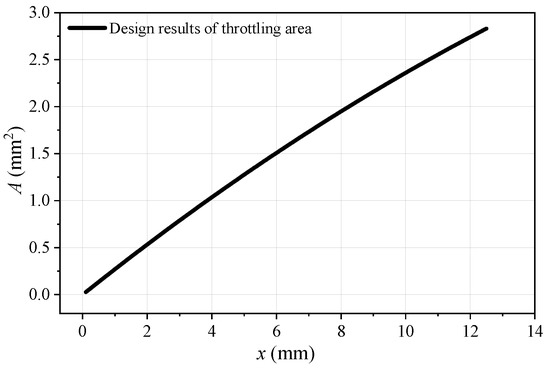
Figure 4.
Design throttling area of the variable-area cavitating venturi corresponding to the pintle stroke.
When the pressure at the inlet of the variable-area cavitating venturi was almost constant and it was in a state of cavitation, the flow rate of the oxidizer was determined by the pintle stroke. The latter and the flow rate of the variable-area cavitating venturi obeyed the following relationship [32,33,34]:
In Equation (6), Q is the mass flow rate (unit: kg/s), Cd is the coefficient of flow, A is the throttling area (unit: m2), ρ is the density of the liquid (unit: m2), p1 is the total pressure at the inlet of the variable-area cavitating venturi (unit: MPa), ps is the saturated vapor pressure of the fluid at a given temperature (unit: MPa), x is the pintle stroke (unit: mm), and a and b are constant coefficients measured by the cold flow test. In the test, the inlet pressure of the venturi was 6 MPa; the outlet pressure of the venturi was atmospheric pressure. The temperature of the ultrapure water was room temperature, about 15 °C. The results of the cold flow test of the variable-area cavitating venturi are shown in Figure 5.
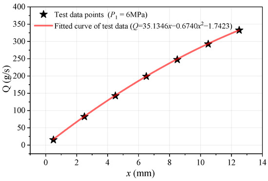
Figure 5.
Results of the cold flow test of the variable-area cavitating venturi.
The fluid used for the cold flow test was ultrapure water, and the correspondence between its flow rate and the strokes of the pintle can be represented as follows:
In Equation (7), QH2O is the mass flow rate of ultrapure water (unit: g/s) and x is the pintle stroke (unit: mm).
2.6. Static Characteristics of Hybrid Rocket Motors
The process of thrust control of hybrid rocket motors has time-varying and time-lag characteristics. The time-varying characteristics occur because the regression rate, area of combustion, and diameter of the throat of the nozzle are variable, and this results in a correspondence between the flow rate of the oxidizer and the thrust with respect to the duration of operation of the motor. The time-lag characteristic occurs because the injection of the oxidizer, pyrolysis of fuel, combustion of the propellant, and energy conversion in the nozzle do not occur instantaneously, but require a certain response time.
The control system simplifies the process of thrust response of the motor into a quasi-steady-state process. The controller needs to use static characteristics to solve for the magnitude of displacement of the pintle corresponding to the error in the thrust in each control cycle. The change in the stroke of the pintle is obtained from that in the flow rate of the oxidizer, which is in turn obtained from the error in the thrust.
Before introducing the static characteristics of the hybrid rocket motor, we introduce the concept of the specific impulse of the oxidizer Iox to calculate the control parameters.
In Equation (8), Iox is the specific impulse of the oxidizer, F is the thrust, and is the flow rate of the oxidizer. The specific impulse of the oxidizer represents the thrust produced per unit mass of the oxidizer. This is different from the specific impulse that indicates the thrust produced per unit mass of the oxidizer and the fuel.
Thus, the thrust of the motor can be expressed as the product of the flow rate of the oxidizer and its specific impulse Iox:
In Equation (9), Isp is the specific impulse and is the mass flow rate of fuel. The relationship between the specific impulse and the specific impulse of the oxidizer is as follows:
The above relationship was calculated by using rocket propulsion analysis (RPA) software, as shown in Figure 6. The oxidizer consisted of 98% hydrogen peroxide, the fuel consisted of 42% HTPB with 58% of an aluminum additive, and the ratio of expansion of the nozzle was three.
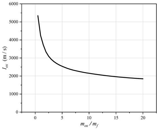
Figure 6.
Specific impulses of the oxidizer under different oxidizer-to-fuel mass ratios.
As shown in Figure 6, the specific impulse of the oxidizer decreased with an increase in the oxidizer-to-fuel mass ratio by internal ballistic calculation. The initial conditions were as follows: The nozzle expansion ratio was 3; the combustion chamber pressure was 3 MPa. The impact of combustion pressure on the specific pulse was slight reflecting the feature of hybrid rocket motors [31]. Therefore, the impact was not considered. During the operation of the motor, the mass flow rate of the oxidizer remained constant while the ratio of the mixture varied in response to changes in the mass flux. This indicates that the specific impulse of the oxidizer changed during the operation of the motor.
For example, when the oxidizer-to-fuel mass ratio was one, the specific impulse of the oxidizer was 4249 N·s/kg. That is, assuming an oxidizer-to-fuel ratio of one, a flow rate of the oxidizer of 1 kg/s resulted in a motor thrust of 4249 N. When the oxidizer-to-fuel mass ratio was three, the same flow rate of the oxidizer (1 kg/s) generated a thrust of only 2923 N. The time-varying nature of hybrid rocket motors can thus be explained by the fact that the same flow rate of the oxidizer resulted in varying levels of thrust.
We needed to carry out internal ballistic calculations on the hybrid rocket motor to obtain an accurate range of variations in the oxidizer-to-fuel mass ratio during the operation of the motor. We set the inner diameter of the tube grain to 25 mm, its outer diameter to 100 mm, and its length to 375 mm. We used measurements made by our team in the equation of the regression rate [15].
In Equation (11), is the regression rate (unit: mm/s) and Gox is the mass flux of the oxidizer (unit: kg/m2·s).
In Equation (12), AP is the cross-sectional area of flow of the oxidizer (unit: m2) and d is the inner diameter of the tube grain (unit: m).
The mass flow rate of fuel can be obtained by the equation for the regression rate.
In Equation (13), ρf is the density of the fuel (unit: kg/m3)—we used 42% HTPB and 58% Al, with a density of 1634 kg/m3—and Ab is the area of combustion (unit: m2).
We calculated the area of combustion of the tube grain as follows:
In Equation (14), L is the length of the tube grain (unit: m).
In Equation (15), eburned is the web thickness of the burned grain (unit: mm), t is the working time (unit: s), and (t) is the regression rate (unit: mm/s) corresponding to the moment t. is assumed to be constant along the axes of the fuel rod.
The steady-state pressure of the combustion chamber of the hybrid rocket motor was obtained as follows:
In Equation (16), Pc is the pressure of the combustion chamber (unit: Pa), c* is the characteristic velocity (unit: m/s) obtained by thermal calculation with RPA (rocket propulsion analysis) software, and At is the throttling area of the nozzle throat (unit: m2). In detail, c* depends on the oxidizer-fuel ratio and the combustion chamber pressure. When the oxidizer-fuel ratio is constant, c* and Pc are interacting and coupled. The exact Pc and c* are calculated in four iterations. Specifically, the first step is to set an initial Pc. The second step is to obtain c* by interpolating Pc and the oxidizer-fuel ratio. Next, we use c* to obtain the iterated Pc. Finally, Pc is updated and the program returns to the second step. When the number of iterations is greater than four, the calculation is terminated and Pc is considered to be converged.
Internal ballistic calculations were performed for the tube grain with a flow rate of the oxidizer of 160 g/s of hydrogen peroxide. This yielded a curve of the oxidizer-to-fuel mass ratio corresponding to different web thicknesses of the burned grain.
Curves of the specific impulses of the oxidizer for different web thicknesses of the burned grain are shown in Figure 7. The variation of Iox was due to the premises that the oxidizer flow rate was 160 g/s and that both the oxidizer-fuel ratio and pressure varied. As shown in the conclusion in reference [31], in hybrid rocket motors, the effect of combustion chamber pressure on the specific impulse was slight. Therefore, the effect of combustion chamber pressure on Isp and Iox was not considered in this paper. As the combustion of the tube grain proceeded, the oxidizer-to-fuel mass ratio gradually increased from 1.5 at the outset to 4.2. However, the specific impulse of the oxidizer gradually decreased from 3698 m/s to 2648 m/s. This indicates that an initial flow rate of the oxidizer of 160 g/s generated a thrust of 592 N, whereas at the end of the process, the same flow rate generated a thrust of 423.6 N: a 20.6% decrease in thrust. The correspondence between the thrust and the pressure of the combustion chamber, and the web thickness of the burned grain is shown in Figure 8.
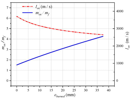
Figure 7.
Variations in the oxidizer-to-fuel mass ratio and a specific impulse of the oxidizer with different web thicknesses of the burned grain.
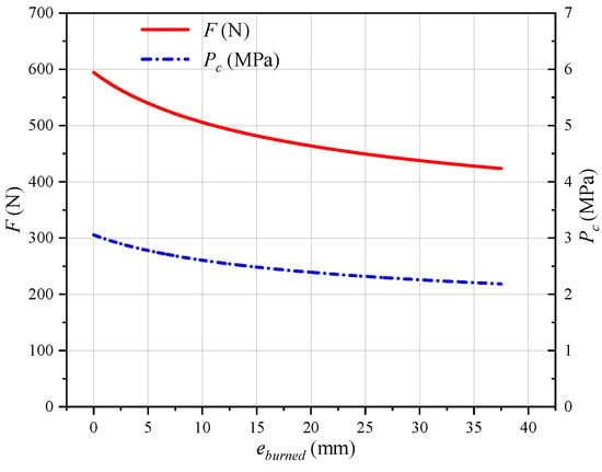
Figure 8.
Variations in the thrust and the pressure of the combustion chamber with different web thicknesses of the burned grain.
2.7. Solving for the Control Parameters
The control parameters in this paper needed to be provided on a case-by-case basis. Open-loop control was used during the periods of ignition and shutdown of the motor, and closed-loop control was ineffective. Closed-loop control was switched on when the motor was operating normally. Different values of the control parameters were used in the closed-loop control stage by determining whether the absolute value of the error signal |error(k)| was greater than the set threshold ε.
The error signal error(k) in the k-th control cycle is as follows:
Fd(k) and F(k) are the set thrust and the actual output thrust in the k-th control cycle, respectively, and ΔF(k) is an error in the thrust that is equal to error(k).
First, we set the control period to 20 ms based on the quasi-steady-state assumption. During the first half of the control cycle (0–10 ms), the pintle of the valve was actuated, the flow rate changed, and the thrust was adjusted. However, in the second half of the control cycle (10–20 ms), the pintle of the valve was fixed, the flow tended to stabilize, and the thrust and the pressure in the chamber were steady. We assumed that the hybrid rocket motor had reached the quasi-steady state by the end of the control cycle (20 ms).
Second, we used the segmented PID algorithm to set the threshold ε > 0, and divided the process of transition into three stages according to the error signal.
Stage 1: Saturation output. When the error in the thrust signal was too large (|error(k)| > 100 N), the control output was saturated, and the speed of adjustment of the pintle of the valve reached its limit of saturation. This limit was the maximum permitted speed of adjustment of the pintle, 4.3 mm/s. Equivalently, the rate of change of flow was limited to 133 g/s2, where this was approximately equal to a rate of change in thrust of 567 N/s.
Stage 2: Rapid transition. When the error in the thrust signal was large (100 N > |error(k)| > 20 N), large control parameters (kp0, ki0, and kd0) were used. The stage of rapid transition was designed to improve the transition-related performance and reduce the response time.
Stage 3: Slow convergence. When the error in the thrust signal was small (20 N > |error(k)|), smaller control parameters (kp1, ki1, and kd1) were used. The stage of slow convergence was designed to improve the accuracy and stability of control.
Finally, the control parameters were calculated by using static characteristics. Figure 7 shows that when the flow rate of hydrogen peroxide was maintained at 160 g/s, the specific impulse of the oxidizer decreased from 3698 m/s to 2648 m/s over the period of operation of the motor.
In Equation (18), F is the thrust (unit: N), is the mass flow rate of the oxidizer (unit: kg/s), and Iox is the specific impulse of the oxidizer (unit: m/s). Its range of values was obtained from internal ballistic calculations. The tube grain used in this paper had a range of specific impulses of the oxidizer of 3698 to 2648 m/s from the initial surface of the combustion until the end of combustion.
Since the density of 98% hydrogen dioxide is 1.4 times larger than ultra water, the mass flow rate of ultra water is multiplied by when inlet pressures are the same (P1 = 6 MPa) to obtain the mass flow rate of hydrogen dioxide. Here, we set the inlet pressure and the saturation vapor pressure to 6 MPa and 0, respectively. The reason for this value is twofold. First, the saturation vapor pressure of water at 15 °C was 1705.6 Pa. The saturation vapor pressure was so smaller than the inlet pressure, around 6 MPa that it was regarded as 0. Second, the upstream pressure did not change violently in the test process and the error caused by the minor change could thus be omitted. Accordingly, we set the inlet pressure to a fixed value of 6 MPa.
where x is the displacement of the pintle (unit: mm) in the range of 0 to 13 mm, obtained from the cold test of the variable-area cavitating venturi. In Equation (19), the unit of is kg/s; the unit of x is mm.
Each variable was discretized to calculate the discrete state of the output of the controller.
The values of the thrust, flow rate, and displacement of the pintle in the k-th control cycle (t = kT) were F(k), (k), and x(k), respectively. When the hybrid rocket motor reached the quasi-steady state, it satisfied the following quasi-steady state equations:
The units of and x in Equation (21) are the same as in Equation (19). Similarly, the quasi-steady state equation for the (k − 1)-th control cycle, i.e., t = (k − 1)T, is as below.
By using Equations (20) and (22), we obtain:
The thrust F(k), mass flow rate of oxidizer (k), and displacement of the pintle x(k) at the end of the k-th control cycle can be calculated by adding F(k − 1), (k − 1), x(k − 1), and ΔF(k) to Δ(k) and Δx(k).
The specific impulse of the oxidizer ranged from 2955 m/s to 3689 m/s because the duration of operation of the hybrid rocket motor in this hot test was 21 s. To be specific, during the internal ballistic calculation at 21 s, Iox and Isp were 2955 m/s and 2195 m/s, respectively; oxidizer flow rate was 160 g/s; the oxidizer–fuel ratio was 2.9; Pc was 2.4 MPa; F was 472.8 N, and the thickness of burned flesh was 17.3 mm. When the time changed from 0 s to 21 s, the specific impulse of the oxidizer decreased from 3698 m/s to 2955 m/s.
In this paper, the same set of control parameters was used for the whole ignition period for the sake of realizability and reliability. Iox was set as the average value of 2955 m/s and 3698 m/s (3326.5 m/s). We assumed that the specific impulse of the oxidizer was constant throughout the period of operation, and this enabled us to obtain constant control parameters. The unit of 3326.5 below is m/s.
By using Equations (22) and (24), we obtain:
A variable-area cavitating venturi is regarded as a linear component owing to its high linearity.
By using Equations (25) and (27), we obtain:
The units of ΔF(k), Δ, and Δx(k) are N, kg/s, and mm, respectively. Thus, ΔF(k), the error in thrust in the current control cycle, can be calculated. Δx(k) is then solved for:
By using Equations (4) and (30), we obtain:
Then, we know that kp0 = 0, ki0 = 0.007130, and kd0 = 0. Meanwhile, we set kp1 = 0, ki1 = 500, ki0 = 3.565, and kd0 = 0 based on the previous tests.
3. Experimental Setup
The experimental system consisted of three subsystems: a throttleable hybrid rocket motor, an oxidizer feeding system, and a measurement and control system.
3.1. Throttleable Hybrid Rocket Motor
Figure 9 shows a drawing of the assembly of the throttleable hybrid rocket motor. It consisted of a catalyst bed, a pre-combustion chamber, a fuel grain, a post-combustion chamber, and a nozzle (the physical photograph is shown in Figure 10). The material of the nozzle is tungsten-infiltrated copper which can be cooled down by regenerative cooling.
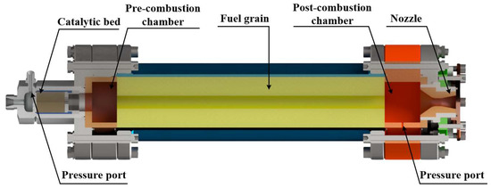
Figure 9.
Drawing of the assembly of the throttleable hybrid rocket motor.
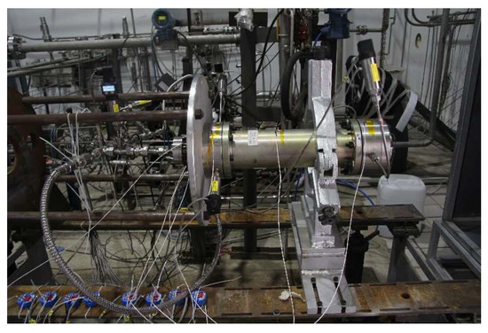
Figure 10.
Photograph of the components of the hybrid rocket motor.
The catalyst bed is the igniter of the motor. Hydrogen peroxide was decomposed into oxygen and water vapor by the catalyst bed. The temperature of the catalytic products, oxygen, and water vapor, exceeded 1100 K. The high-temperature oxygen and water vapor thus ignited the motor.
Table 1 lists the main design parameters of the throttleable hybrid rocket motor.

Table 1.
Main design parameters of the throttleable hybrid rocket motor.
3.2. Oxidizer Feeding System
Figure 11 shows a schematic of the oxidizer feeding system. It was composed of a high-pressure gas tank, a pressure regulator, hand valves, solenoid valves, a buffer tank, pressure transducers, a mass flowmeter, a variable-area cavitating venturi, and other components. The high-pressure gas tank contains nitrogen gas to exert pressure on the oxidizer tank.
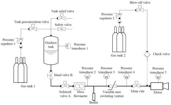
Figure 11.
Schematic of the oxidizer feeding system.
3.3. Measurement and Control System
The test system used a programmable logic controller (PLC) to control the variable-area cavitating venturi. A general automatic test system based on the PXI bus was used to collect the experimental data on the temperature, pressure, mass flow rate, and thrust, and the rate of sampling during the test was 2000 Hz. The repeated accuracy of positioning of the pintle stroke of the variable-area cavitating venturi was 0.02 mm and the accuracy of the displacement sensor was 10 microns. An Emerson mass flowmeter with a range of 0–360 g/s, a measurement accuracy at the level of 0.1, and a measurement error of less than 0.1% was used to measure the mass flow rate. The S-type tensile pressure sensor was used to measure the thrust. The range of the sensor used to measure thrust was 0–1 kN, and the error in the measured thrust was smaller than 0.2%. Error in the measurement of each pressure sensor was smaller than 1.5%. Table 2 lists the error range and basic information of measurement components.

Table 2.
Error range and basic information of measurement components.
4. Experimental Results and Discussion
We performed a closed-loop throttle test to evaluate the performance of the segmented PID control system. The measured thrust was used as the feedback measurement for the hot test, and 98% hydrogen peroxide and HTPB with 58% of aluminum additive were used as the propellant for the closed-loop throttle test.
4.1. Time Sequence of Test
Figure 12 shows the temporal sequence of the closed-loop throttle test. Before the closed-loop control switch was opened at 4 s, the main valve was opened at 1 s and the oxidizer had thus been available for 3 s. This was intended to pre-heat the catalytic bed and prepare for grain ignition. The core component of the 45 mm-diameter catalytic bed was composed of nickel-based silver meshes catalyzing and decomposing hydrogen peroxide efficiently due to the good catalytic property of silver monomers. Before the main value was turned off at 26 s, the closed-loop control switch was turned off at 25 s to avoid the incorrect action of the pintle of the control valve under the command of the feedback control system during the shutdown process.
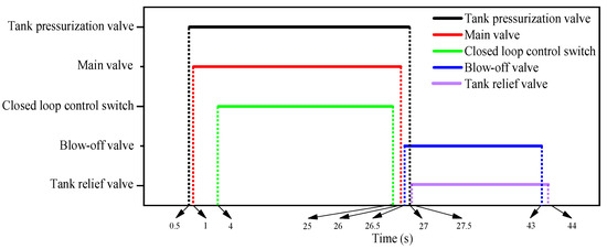
Figure 12.
Time sequence of the closed-loop throttle test.
4.2. Closed-Loop Throttle Test
Figure 13 shows the time history of the response profile of the thrust of the motor. The prescribed profile of thrust was divided into three steady stages. The target values of thrust in the three stages were 400 N, 600 N, and 400 N, and the average thrust values of the stable section in each stage were 400.7 N, 599.1 N, and 400.1 N, respectively. The average thrust was thus stable and the control error of the average value of the thrust was better than 0.5%. Although the average thrust was very close to the target value, the instantaneous values of thrust were not stable in the three steady stages, and steady-state error was obtained. Figure 14 illustrates the snapshots of plume exhausting from the nozzle for the hot test photographed by an infrared camera.
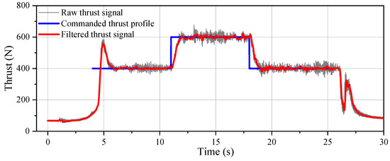
Figure 13.
Response profile of the thrust in the closed-loop throttle test.

Figure 14.
Snapshots of plume exhausting from the nozzle for the hot test at (a) 8 s, (b) 15 s, and (c) 23 s.
Ablation of the nozzle occurred due to the large amount of aluminum particles in the fuel. The nozzle throat diameters before and after the test were 14.787 mm and 15.132 mm, respectively, with a difference of 0.345 mm. The fuel consumption was obtained as 1.715 kg by the mass weighing method.
Because the period of control in this study was set to 20 ms, the cut-off frequency of the filter was set to 50 Hz. The filtered curves of the thrust over time were then obtained as shown in Figure 15. The real-time error in the thrust was controlled to within ± 20 N with a steady-state error smaller than 5%.
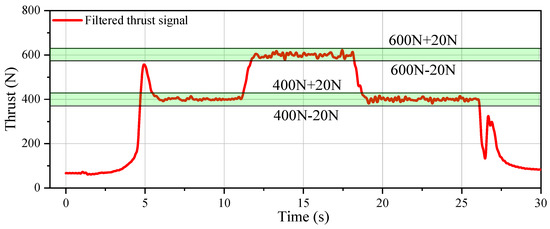
Figure 15.
Filtered curves of the thrust over time with an error band.
4.3. Discussion
We used the instantaneous regression rate-based method (IRRM) previously developed by our team to obtain the real-time regression rate of the motor and the real-time mass flow rate of the fuel [30]. The curves of variations in the regression rates and mass flow rate of fuel are shown in Figure 16. As combustion proceeded, the regression rate gradually decreased, but when the thrust was 600 N, the flow rates of the oxidizer and mass flux increased first, followed by an increase in the regression rate. The mass flow rate of the fuel did not vary greatly in each section of stable thrust due to the joint effects of the gradually decreasing regression rate and the gradually increasing area of combustion.
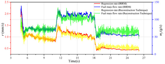
Figure 16.
Curves of variation in the regression rate and mass flow rate of the fuel.
In consideration of the thrust throttling operation of the motor, the reconstruction technique proposed in previous articles [35,36] was referred to in order to obtain the real-time c* and a more accurate regression rate and fuel flow rate, which is shown in Figure 16. Compared with the IRRM method, the OPTMA-FE-L method added real-time information about the thrust and took into account the real-time variation of c*.
Curves of variations in the oxidizer-to-fuel mass ratio and the specific impulse of the oxidizer are shown in Figure 17. The oxidizer-to-fuel ratio and the specific impulse of the oxidizer changed slightly in the first two stages of steady thrust. The oxidizer-to-fuel ratio gradually increased in the third section of steady thrust, and this led to a gradual decrease in the specific impulse of the oxidizer, mainly because of the low mass flux and the reduced regression rate in the late stage of combustion.
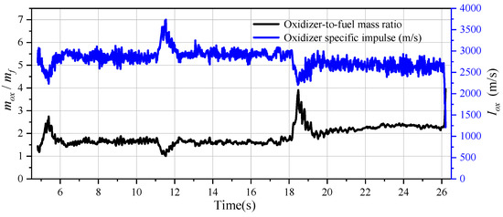
Figure 17.
Curves of variations in the oxidizer-to-fuel mass ratio and the specific impulse of the oxidizer.
When calculating the control parameters, we assumed that the average specific impulse of the oxidizer was 3326.5 m/s during the entire process of operation. The actual average specific impulses of the oxidizer at three stages were 2864.9 m/s, 2930.8 m/s, and 2663 m/s, respectively, and the errors were 13.8%, 11.9%, and 19.9% all of which are lower than 20%. The experimental results show that the actual specific impulse of the oxidizer is consistent with its pre-set specific impulse. At the same time, in the internal ballistic calculation, the actual specific impulse of the oxidizer was lower than the pre-set specific impulse because the efficiency of the specific impulse was not considered. Therefore, a difference between them was obtained.
As the combustion progressed, the nozzle ablation occurred. The diameter of the nozzle throat gradually increased whereas the specific impulse of the oxidizer decreased. Thus, the specific impulse of the oxidizer in the third stage was lower than that in the first stage.
Figure 18 shows curves of the variations in the thrust, mass flow rate of the oxidizer, and position of the pintle over time during the closed-loop throttle test. It also illustrates the thrust signals collected. The thrust generated by 0 s was the initial compression. The purpose of the initial compression was to prevent thrust shock during the ignition of the motor in order to better collect thrust signals. The initial compression had been subtracted in the subsequent data processing. According to Figure 18, the peak thrust at the beginning of ignition occurred due to the delay in ignition. Because the catalytic bed had not been fully preheated and the motor had not completed ignition, the real-time thrust was much lower than the design thrust. Error in the thrust signals received by the controller of the control system was too large, and led to a significant increase in the position of the pintle. This in turn increased the mass flow rate of the oxidizer and the thrust.
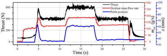
Figure 18.
Curves of variations in the thrust, mass flow rate of the oxidizer, and position of the pintle over time in the closed-loop throttle test.
Although the control period in this paper was set to 20 ms, the control system could not suppress the low-frequency oscillations in thrust. The main frequency of oscillations in the thrust was 24 Hz, based on the Fourier transform of signals of the thrust sensor. To easily analyze the variations in the control parameters, signals of the sensor were discretized to obtain the increases in the thrust, mass flow rate of oxidizer, and the pintle stroke. The specific procedure was as follows: The measurements of the sensor were filtered by a third-order Butterworth filter with a cut-off frequency of 30 Hz. We then selected one data point every 12 Hz from the filtered data; Finally, pairs of adjacent data points were subtracted from each other, that is, the increase in each physical quantity was obtained every 83.33 ms.
Figure 19 shows the curves of variations in the increases in the thrust, mass flow rate of the oxidizer, and the position of the pintle over time. The four green lines in the figure correspond to turning on feedback control, instantaneously increasing the target thrust to 600 N, instantaneously reducing the target thrust to 400 N, and turning off feedback control. Different from Figure 18, the change at 2 s in Figure 19 stems from the thrust generated by the catalytic bed in its initial working stage. The catalytic bed catalyzed and decomposed hydrogen peroxide into high-temperature gas, which expanded through the nozzle to generate thrust. At this point, the hybrid rocket motor was regarded as a hydrogen peroxide monopropellant rocket motor. At 4 s, feedback control was turned on and the control system increased the flow rate to speed up the ignition of the motor. This led to a large overshoot in thrust. This was not a bug in the control system, but occurred because the delay in ignition was too long. At 11 s, the target thrust was modified to 600 N. The position of the pintle and the flow rate increased rapidly, yet the thrust did not respond immediately to these changes. The delay in the period of increase in the thrust was approximately 160 ms. The stepwise response time was 0.83 s. At 18 s, the target thrust was modified to 400 N. The thrust response was fast in the stage of decline and the delay was only 15 ms. The response time in the stepwise descent phase was 0.78 s. At 25 s, feedback control was turned off and the position of the pintle no longer changed.
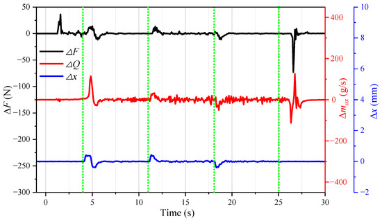
Figure 19.
Curves of variations in the increases in the thrust (ΔF), mass flow rate of the oxidizer (Δ), and position of the pintle (Δx) over time in the closed-loop throttle test.
Figure 20 shows the curves of pressure obtained from each pressure sensor during the closed-loop throttle test. Although the downstream pressure of the venturi and that in the combustion chamber changed, the upstream pressure of the venturi did not change significantly, indicating that the variable-area cavitating venturi had effectively isolated fluctuations in the downstream pressure.
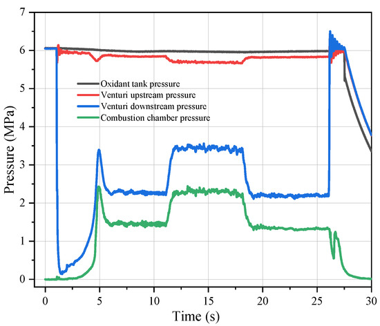
Figure 20.
Curves of pressure obtained from each pressure sensor in the closed-loop throttle test.
5. Conclusions
In this study, the authors conducted a closed-loop thrust throttle test to maintain a constant average thrust in a hybrid rocket motor composed of 98% hydrogen peroxide and HTPB with 58% of an aluminum additive. A segmented PID controller was applied to ensure the smooth transition of the variable thrust. The findings of this paper are as follows: First, the segmented PID controller was used to realize a high-performance hybrid rocket motor. The closed-loop throttle control strategy was effective in ensuring a constant thrust during the operation of the motor. The results show that the average values of thrust in the stable section in each stage were 400.7 N, 599.1 N, and 400.1 N when the target values of thrust were 400 N, 600 N, and 400 N, respectively. The average thrust was thus stable and the average accuracy of thrust control was better than 0.5%. The real-time error in thrust was controlled to within ± 20 N with a steady-state error smaller than 5%.
Second, the results here experimentally verify the effectiveness of closed-loop throttle control for a high-performance hybrid rocket motor with a high mass fraction of aluminum. Thrust throttle control was achieved in the proposed scheme by using a variable-area cavitating venturi to isolate fluctuations in the downstream pressure. The measured thrust was used as the feedback measurement. The parameters of closed-loop throttle control were derived from the specific impulse of the oxidizer, which was obtained in turn from the internal ballistics of the hybrid rocket motor and did not require multiple tests to tune the parameters.
Third, closed-loop control can solve the problem of oscillations in the thrust of the hybrid rocket motor containing 58% of an aluminum additive. The average thrust was stable during the entire period of operation of the motor, and no large fluctuation in it was observed. During the closed-loop throttle test with a duration of 21 s, the average thrust remained close to the target value without any significant fluctuation. This is an important difference between the tests reported here and the hot test conducted under open-loop control.
Author Contributions
Conceptualization, G.T. and H.T; methodology, G.T. and H.T.; software, G.T. and Y.Z.; validation, Z.W. and Z.G.; formal analysis, G.T. and Y.Z.; investigation, G.T. and Y.Z.; resources, G.T. and J.G.; data curation, G.T. and J.G.; writing—original draft preparation, G.T. and H.T.; writing—review and editing, G.T., Z.W. and Z.G.; visualization, G.T. and J.G.; supervision, H.T. and G.C.; project administration, H.T. and G.C.; funding acquisition, H.T. and G.C. All authors have read and agreed to the published version of the manuscript.
Funding
This research was funded by the National Natural Science Foundation of China, grant number U20B2034.
Data Availability Statement
Data is contained within the article.
Conflicts of Interest
The authors declare no conflict of interest.
Nomenclature
| Variables | QH2O | mass flow rate of ultrapure water, g/s | |
| Isp | specific impulse, m/s | ||
| u(k) | controller output of kth control cycle | F | thrust, N |
| u(k − 1) | controller output of (k − 1)th control cycle | mass flow rate of oxidizer, kg/s | |
| error(k) | deviation in the control signal of kth control cycle | mass flow rate of fuel, kg/s | |
| kp, ki, and kd | PID control parameters | Iox | specific impulse of oxidizer, m/s |
| yd(k) | set value | regression rate, mm/s | |
| y(k) | measured value | Gox | mass flux of oxidizer, kg·s−1·m2 |
| Δu(k) | increment in controller output | AP | cross-sectional area of flow of oxidizer, m2 |
| ε | threshold value | d | inner diameter of tube grain, m |
| kp0, ki0, and kd0 | large PID control parameters | ρf | fuel density, kg/m3 |
| kp1, ki1, and kd1 | small PID control parameters | Ab | combustion area, m2 |
| Q | mass flow rate, kg/s | L | length of tube grain, m |
| Cd | flow coefficient | eburned | web thickness of burned grain, mm |
| A | throttling area, m2 | Pc | pressure of combustion chamber, MPa |
| ρ | liquid density, kg/m3 | c* | characteristic velocity, m/s |
| p1 | total inlet pressure of the variable-area cavitating venturi, MPa | At | throttling area of the nozzle throat, m2 |
| ps | saturated vapor pressure of the fluid at a given temperature, MPa | Fd(k) | set thrust value, N |
| x | pintle stroke, mm | F(k) | actual output thrust value, N |
| a, b | constant coefficients | ΔF(k) | error in thrust value, N |
References
- Okninski, A.; Kopacz, W.; Kaniewski, D.; Sobczak, K. Hybrid Rocket Propulsion Technology for Space Transportation Revisited–Propellant Solutions and Challenges. FirePhysChem 2021, 1, 260–271. [Google Scholar] [CrossRef]
- Casalino, L.; Masseni, F.; Pastrone, D. Hybrid Rocket Engine Design Optimization at Politecnico di Torino: A Review. Aerospace 2021, 8, 226. [Google Scholar] [CrossRef]
- Mazzetti, A.; Merotto, L.; Pinarello, G. Paraffin-Based Hybrid Rocket Engines Applications: A Review and a Market Perspective. Acta Astronaut. 2016, 126, 286–297. [Google Scholar] [CrossRef]
- Austin, B.; Heister, S.; Dambach, E.; Meyer, S.; Wernimont, E. Variable Thrust, Multiple Start Hybrid Motor Solutions for Missile and Space Applications. In Proceedings of the 46th AIAA/ASME/SAE/ASEE Joint Propulsion Conference & Exhibit, Nashville, TN, USA, 25–28 July 2010. [Google Scholar]
- Lee, D.; Han, S.; Moon, H. Development of 200 N-class Throttleable Hybrid Rocket Motor for Lunar Module Application. FirePhysChem 2021, 1, 251–259. [Google Scholar] [CrossRef]
- Stoll, E.; Härke, P.; Linke, S.; Heeg, F.; May, S. The Regolith Rocket—A Hybrid Rocket Using Lunar Resources. Acta Astronaut. 2021, 179, 509–518. [Google Scholar] [CrossRef]
- Casalino, L.; Masseni, F.; Pastrone, D. Optimal Design of Electrically Fed Hybrid Mars Ascent Vehicle. Aerospace 2021, 8, 181. [Google Scholar] [CrossRef]
- Kara, O.; Karakaş, H.; Karabeyoğlu, M.A. Hybrid Rockets with Mixed N2O/CO2 Oxidizers for Mars Ascent Vehicles. Acta Astronaut. 2020, 175, 254–267. [Google Scholar] [CrossRef]
- Liu, L.-L.; He, X.; Wang, Y.; Chen, Z.-B.; Guo, Q. Regression Rate of Paraffin-based Fuels in Hybrid Rocket Motor. Aerosp. Sci. Technol. 2020, 107, 106269. [Google Scholar] [CrossRef]
- Pal, Y.; Ravikumar, V. Mechanical Characterization of Paraffin-Based Hybrid Rocket Fuels. Mater. Today Proc. 2019, 16, 939–948. [Google Scholar] [CrossRef]
- Paccagnella, E.; Santi, M.; Ruffin, A.; Barato, F.; Pavarin, D.; Misté, G.A.; Venturelli, G.; Bellomo, N. Testing of a Long-Burning-Time Paraffin-Based Hybrid Rocket Motor. J. Propuls. Power 2019, 35, 432–442. [Google Scholar] [CrossRef]
- Wu, Y.; Zhang, Z.; Wang, Q.; Wang, N. Combustion Characteristics of Skeleton Polymer Reinforced Paraffin-Wax Fuel Grain for Applications in Hybrid Rocket Motors. Combust. Flame 2022, 241, 112055. [Google Scholar] [CrossRef]
- Wang, Y.; Hu, S.-Q.; Liu, X.-L.; Liu, L.-L. Regression Rate Modeling of HTPB/Paraffin Fuels in Hybrid Rocket Motor. Aerosp. Sci. Technol. 2022, 121, 107324. [Google Scholar] [CrossRef]
- Thomas, J.C.; Paravan, C.; Stahl, J.M.; Tykol, A.J.; Rodriguez, F.A.; Galfetti, L.; Petersen, E.L. Experimental evaluation of HTPB/paraffin fuel blends for hybrid rocket applications. Combust. Flame 2021, 229, 111386. [Google Scholar] [CrossRef]
- Tian, H.; Wang, Z.; Guo, Z.; Yu, R.; Cai, G.; Zhang, Y. Effect of Metal and Metalloid Solid-Fuel Additives on Performance and Nozzle Ablation in a Hydroxy-terminated Polybutadiene based Hybrid Rocket Motor. Aerosp. Sci. Technol. 2022, 123, 107493. [Google Scholar] [CrossRef]
- Guo, Z.; Tian, H.; Wang, Z.; Meng, X.; Cai, G. Numerical and Experimental Study on 95% Hydrogen Peroxide Catalytic Ignition of Hybrid Rocket Motors with HTPB-based Aluminum Additive Fuel. Acta Astronaut. 2022, 195, 98–108. [Google Scholar] [CrossRef]
- Liu, Y.; Guan, Y.; Li, J.; Liu, P.; Zhang, X. Insulator Ablation Modes in Different Impact Conditions of Alumina Droplets onto Wall Surfaces. Acta Astronaut. 2018, 153, 138–145. [Google Scholar] [CrossRef]
- Karakas, H.; Kahraman, B.; Ozkol, I.; Karabeyoglu, A. Hybrid Rocket Nozzle Erosion with Microaluminum-Added Fuel. J. Propuls. Power 2022, 38, 901–910. [Google Scholar] [CrossRef]
- Ozawa, K.; Shimada, T. Performance of Mixture-Ratio-Controlled Hybrid Rockets Under Uncertainties in Fuel Regression. J. Propuls. Power 2021, 37, 86–99. [Google Scholar] [CrossRef]
- Casalino, L.; Masseni, F.; Pastrone, D. Robust Design Approaches for Hybrid Rocket Upper Stage. J. Aerosp. Eng. 2019, 32, 04019087. [Google Scholar] [CrossRef]
- Cui, P.; Li, Q.; Cheng, P.; Chen, L. System Scheme Design for LOX/LCH4 Variable Thrust Liquid Rocket Engines Using Motor Pump. Acta Astronaut. 2020, 171, 139–150. [Google Scholar] [CrossRef]
- Yue, C.; Li, J.; Hou, X.; Feng, X.; Yang, S. Summarization on Variable Liquid Thrust Rocket Engines. Sci. China Ser. E Technol. Sci. 2009, 52, 2918–2923. [Google Scholar] [CrossRef]
- Song, A.; Wang, N.; Li, J.; Ma, B.; Chen, X. Transient Flow Characteristics and Performance of a Solid Rocket Motor with a Pintle Valve. Chin. J. Aeronaut. 2020, 33, 3189–3205. [Google Scholar] [CrossRef]
- Guo, C.; Wei, Z.; Xie, K.; Wang, N. Thrust Control by Fluidic Injection in Solid Rocket Motors. J. Propuls. Power 2017, 33, 815–829. [Google Scholar] [CrossRef]
- Zhao, S.; Cai, G.; Tian, H.; Yu, N.; Zeng, P. Experimental Tests of Throttleable H2O2/PE Hybrid Rocket Motors. In Proceedings of the 51st AIAA/SAE/ASEE Joint Propulsion Conference, Orlando, FL, USA, 27–29 July 2015. [Google Scholar]
- Whitmore, S.A.; Peterson, Z.W.; Eilers, S.D. Deep Throttle of a Nitrous Oxide and Hydroxyl-Terminated Polybutadiene Hybrid Rocket Motor. J. Propuls. Power 2014, 30, 78–86. [Google Scholar] [CrossRef]
- Messineo, J.; Shimada, T. Theoretical Investigation on Feedback Control of Hybrid Rocket Engines. Aerospace 2019, 6, 65. [Google Scholar] [CrossRef]
- Whitmore, S.A.; Peterson, Z.W.; Eilers, S.D. Closed-Loop Precision Throttling of a Hybrid Rocket Motor. J. Propuls. Power 2014, 30, 325–336. [Google Scholar] [CrossRef]
- Velthuysen, T.; Brooks, M.; Pitot, J. Closed Loop Throttle Control of a Liquefying Fuel Hybrid Rocket Motor. J. Aerosp. Technol. Manag. 2021, 13, e2421. [Google Scholar] [CrossRef]
- Tian, H.; Wang, Z.; Zhu, H.; Lu, Y.; Gao, J.; Cai, G. Effect of High-Mass Fraction of Aluminum on Catalytic Hybrid Rocket Motor. Appl. Sci. 2022, 12, 13023. [Google Scholar] [CrossRef]
- Guang, T.; Hui, T.; Xianzhu, J.; Ruikai, C.; Yudong, L.; Yuanjun, Z. Experimental Study on Precise Thrust Control of Hydrogen Peroxide and Polyethylene Hybrid Rocket Motors. Acta Astronaut. 2022, 196, 303–313. [Google Scholar] [CrossRef]
- Tian, H.; Zeng, P.; Yu, N.; Cai, G. Application of Variable Area Cavitating Venturi as a Dynamic Flow Controller. Flow Meas. Instrum. 2014, 38, 21–26. [Google Scholar] [CrossRef]
- Zeng, P.; Tian, H.; Yu, N.; Cai, G. Numerical Investigation on Flow in the Variable Area Cavitating Venturi. In Proceedings of the 49th AIAA/ASME/SAE/ASEE Joint Propulsion Conference, San Jose, CA, USA, 14–17 July 2013. [Google Scholar]
- Zhang, X.; Wang, D.; Liao, R.; Zhao, H.; Shi, B. Study of Mechanical Choked Venturi Nozzles Used for Liquid Flow Controlling. Flow Meas. Instrum. 2019, 65, 158–165. [Google Scholar] [CrossRef]
- Carmicino, C.; Sorge, A.R. Influence of a Conical Axial Injector on Hybrid Rocket Performance. J. Propuls. Power 2006, 22, 984–995. [Google Scholar] [CrossRef]
- Saito, Y.; Kamps, L.T.; Tsuji, A.; Nagata, H. Reconstruction techniques for determining O/F in hybrid rockets. In Proceedings of the AIAA Propulsion and Energy 2021 Forum, Virtual Event, 9–11 August 2021. [Google Scholar]
Disclaimer/Publisher’s Note: The statements, opinions and data contained in all publications are solely those of the individual author(s) and contributor(s) and not of MDPI and/or the editor(s). MDPI and/or the editor(s) disclaim responsibility for any injury to people or property resulting from any ideas, methods, instructions or products referred to in the content. |
© 2023 by the authors. Licensee MDPI, Basel, Switzerland. This article is an open access article distributed under the terms and conditions of the Creative Commons Attribution (CC BY) license (https://creativecommons.org/licenses/by/4.0/).