Article

Performance Analysis and Design of Direct Ammonia Fuel Tubular Solid Oxide Fuel Cell for Shipborne Unmanned Aerial Vehicles

1
Marine Engineering College, Dalian Maritime University, Dalian 116026, China
2
National Center for International Research of Subsea Engineering Technology and Equipment, Dalian Maritime University, Dalian 116026, China
*
Author to whom correspondence should be addressed.
Aerospace 2023, 10(5), 397; https://doi.org/10.3390/aerospace10050397
Submission received: 2 March 2023 / Revised: 17 April 2023 / Accepted: 18 April 2023 / Published: 25 April 2023
(This article belongs to the Special Issue Heat Transfer, Combustion and Flow Dynamics in Propulsion Systems)

Abstract

:
Ammonia is being considered as a promising alternative to hydrogen fuel in solid oxide fuel cells (SOFCs) due to its stability and ease of storage and transportation. This study investigates the feasibility of using ammonia fuel in a tubular SOFC for shipborne unmanned aerial vehicles (UAVs). The paper develops a 3D model of a tubular-anode-supported SOFC single cell and conducts numerical simulations to analyze the impact of different operating conditions on SOFC performance. The study optimizes the SOFC’s performance by adjusting its working parameters and overall structure, revealing that increasing temperature and porosity enhance performance, but excessively high values can cause deterioration and instability in the cell. The study also finds that the cathode-supported (CS)-SOFC outperforms the anode-supported (AS)-SOFC, mainly due to its thicker cathode layer, providing better sealing and oxygen supply, resulting in a more uniform current density distribution. The paper provides valuable insights into the potential use of ammonia fuel for shipborne UAVs and offers a foundation for future research and development in the field of SOFCs. The results indicate that increasing the temperature and porosity of the SOFC can enhance battery performance, but excessive values can cause deterioration and instability in the cell. The study also highlights the impact of different operating conditions on SOFC performance, with a significant performance improvement observed in the range of 0.6–0.8 V. Additionally, the CS-SOFC outperforms the AS-SOFC due to its thicker cathode layer, but both have significant potential for development.

1. Introduction

In recent years, the global focus on sustainable development has increased, resulting in a growing demand for carbon-neutral technologies [1]. The development of efficient and clean power systems is not only crucial for shipborne unmanned aerial vehicles (UAVs), but also a key component of transitioning towards a low-carbon economy [2]. Moreover, the availability and sustainability of fuel sources are critical factors in determining the feasibility and long-term viability of a power system for shipborne UAVs [3]. As fossil fuels are gradually depleting and concerns over their environmental impact are increasing, exploring and utilizing alternative fuels has become an urgent and necessary task. Additionally, shipborne UAVs have a broad range of applications, such as maritime surveillance, search and rescue, and ocean monitoring, where long endurance, high reliability, and flexibility are essential requirements [4]. However, traditional power supply systems based on internal combustion engines (ICEs) or batteries cannot meet these requirements. ICEs are noisy, emit pollutants, and require frequent maintenance, while batteries have limited endurance and require frequent recharging [5]. Therefore, the development of a power system that can provide high efficiency, long endurance, and environmental friendliness is critical for the successful deployment and operation of shipborne UAVs in these applications. In this regard, solid oxide fuel cells (SOFCs) have emerged as a promising technology for powering shipborne UAVs [6]. SOFCs can operate on a variety of fuels, including ammonia, which is a clean and renewable fuel source. Ammonia is produced from hydrogen and nitrogen, both of which are readily available and can be produced sustainably through renewable energy sources [7]. Furthermore, the use of ammonia as a fuel for SOFCs does not emit greenhouse gases or other pollutants, making it a highly attractive alternative to traditional fuels [8,9,10]. In summary, the development of an efficient and clean power system for shipborne UAVs is crucial not only for meeting the demands of various applications but also for achieving sustainability and environmental protection goals. The use of SOFCs fueled by ammonia is a promising solution that can address these challenges and offer long-term benefits.
The demand for shipborne UAVs with long endurance, high reliability, and environmental protection has increased, leading to growing interest in developing efficient and clean power systems that contribute to the goal of carbon neutrality [11,12]. SOFCs are a promising technology for powering shipborne UAVs due to their fuel flexibility, high energy efficiency, and low emissions compared to traditional ICEs or battery power supply systems [13,14]. Ammonia is a promising alternative fuel for SOFCs because of its high energy density, low toxicity, and low cost, and it can be produced sustainably from renewable sources [15,16]. However, further research and development is required to optimize the performance design of ammonia-fueled SOFCs for shipborne UAVs, particularly in terms of operating conditions, durability, stability, and compatibility. Such investigations can contribute to the development of efficient and clean power systems for shipborne UAVs and pave the way for the wider application of ammonia fuel cells in transportation sectors. In the era of high energy consumption, SOFCs are being developed as a new and efficient power generation device to meet high standards for energy conservation and environmental protection. Ammonia, as a stable hydrogen carrier, has the potential to become a highly efficient zero-carbon fuel for SOFCs.
Hydrogen fuel cells are a promising technology for high-efficiency and low-emission electricity generation [17]. However, current regulations and standards for hydrogen production, storage, and transport need improvement, posing a significant challenge for implementing a safe and efficient hydrogen infrastructure [18]. To overcome this, on-site hydrogen generation can be used as an alternative solution to provide fuel for ship-based fuel cells, which could greatly accelerate the commercialization of ship-based fuel cell technology [19,20]. Compared to proton exchange membrane fuel cells, SOFCs operate at much higher temperatures, enabling them to produce high-quality waste heat and achieve higher fuel utilization efficiency [21]. Furthermore, all-solid-state SOFCs offer greater flexibility in installation, facilitating the modular design of ship-based power and propulsion systems and making maintenance and upkeep easier [22,23]. Additionally, tubular SOFCs possess excellent sealing properties that can protect the fuel and prevent leakage, while also meeting the requirements for moisture, dust, and salt spray resistance necessary for marine power machinery. Both atmospheric and pressurized SOFC power systems are well suited for modern large ships and their auxiliary power systems, underscoring their potential for widespread adoption in the shipping industry. The adoption of SOFCs in ship-based power generation and propulsion systems could lead to significant reductions in greenhouse gas emissions and improve overall energy efficiency, thereby contributing to a more sustainable future for the marine transportation industry.
Fuel cells that use on-site hydrogen production are the focus of development for fuel cells in marine UAVs [24,25]. SOFCs that generate hydrogen through direct ammonia cracking can achieve a reasonable combination of fuel supply systems and fuel cells with a simple structure. SOFCs are also suitable for use in ship power plants, making direct-ammonia-cracking SOFCs a potential development direction for marine fuel cells [26,27]. In SOFCs fueled by pure hydrogen, hydrogen and oxygen are directly converted into water, and heat is released. However, for a single SOFC with direct ammonia cracking, the reaction is more complicated. First, the ammonia gas enters the high-temperature fuel channel for a cracking reaction to generate nitrogen and hydrogen. Then, the hydrogen produced electrochemically reacts with the oxygen transported by the air channel to realize energy conversion [28,29]. The heat required for ammonia pyrolysis, as an endothermic reaction, can be provided by ambient temperature. Due to the complexity of the reaction and many undetermined details, most studies in the current literature focus on modeling SOFCs fueled by hydrogen [30]. The reaction in SOFCs is strongly temperature dependent, like most chemical reactions. The distribution of the temperature gradient in the fuel cell directly affects the reaction rate and, therefore, the performance of the fuel cell. Conversely, chemical reactions accompanied by exothermic and endothermic reactions also change the distribution of temperature gradients.
Barelli et al. [31] conducted an experimental test and designed a system for operating an SOFC-based power system using ammonia as a fuel. The study demonstrates the feasibility and potential of using ammonia as a fuel for SOFCs, which could have implications for the development of sustainable energy systems. Khodabandeh et al. [32] investigated the impact of using oil/multiwalled carbon nanotube nanofluids and different cooling channel geometries on the cooling performance of SOFCs. The study shows that using nanofluids can enhance the heat transfer performance of SOFC cooling systems, while the geometrical design of the cooling channels can also significantly affect the system’s thermal behavior. Rathore et al. [33] provide a comprehensive review of the progress and prospects of direct ammonia solid oxide fuel cells, highlighting recent advancements in catalyst development, cell design, and system integration, and discussing the challenges and opportunities associated with the technology. Farhad et al. [34] conducted experiments on anode-supported tubular SOFCs and found that the ammonia cracking reaction can suppress temperature increases. They reported that 0.8 L of ammonia could generate 100 W of electricity for 10 h at 0.73 V and 800 °C, indicating that the chemical reactions occurring within the fuel cell have a significant impact on its thermal load. Tariq Nawas et al. [35] established a thermal shock model of a single direct methane steam reforming SOFC and concluded that the methane steam reforming reaction plays a dominant role in generating the thermal load of the cell, highlighting the non-negligible effect of chemical reactions on its thermal load. Buttler et al. [36] observed that every electrochemical reaction has a corresponding thermal neutral voltage. They found that when a fuel cell operates at the thermal neutral voltage, it does not generate or consume more heat. However, operating above or below the thermal neutral voltage consumes more electricity or cools the cell, resulting in temperature gradients inside the cell. Kishimoto et al. [37] developed a 2D mathematical model of ammonia-fueled SOFCs, coupling temperature, material distribution, material flow, and electrochemical properties. They concluded that direct ammonia reforming fuel cells have similar performance to ammonia pre-reforming fuel cells. Kee et al. [38] reported that fuel cell energy density largely depends on the gas composition, particularly the hydrogen content in the mixture. Tan et al. [39] established a three-dimensional model of plate SOFCs with internal ammonia cracking and found that the uneven distribution of current density was mainly caused by the uneven distribution of gas on the air electrode. Hajimolana et al. [40] developed a kinetic model of ammonia tubular SOFCs and found that the internal flow channel size of the fuel cell had the greatest impact on fuel cell efficiency, while the porosity of the cathode had a greater impact on fuel cell performance than the anode. Overall, previous studies have shown that various factors, including chemical reactions, fuel composition, electrode materials, geometric shape, and microstructure parameters, can affect the performance and thermal load of SOFCs.
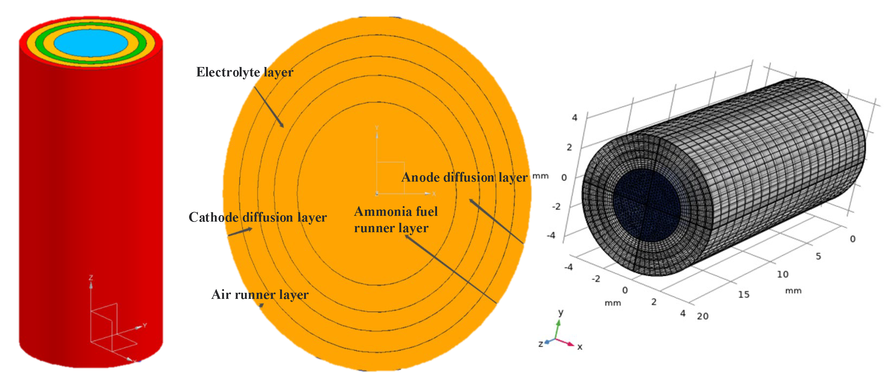
This paper focuses on the use of ammonia as fuel in tubular SOFCs for shipborne UAVs. A three-dimensional model of a tubular anode-supported SOFC single cell was established in COMSOL Multiphysics [41] using steady-state analysis and multiphysics field coupling. Based on the theoretical principles of tubular SOFCs, numerical simulations and analyses of the working conditions of ammonia-fueled SOFCs were conducted. By adjusting the working parameters or overall structure using a controlled variable method, this paper analyzes and optimizes some factors that affect the performance of the cell. Specifically, it describes the process of drawing the geometric model of a tubular single cell, and setting the boundary conditions, physical field modules, and parameter settings. The simulation results, including gas concentration distribution, current density, temperature field, and performance curves, are analyzed accordingly. Furthermore, the paper investigates the impact of several factors on the cell performance, such as operating temperature, electrode layer porosity, and different tubular structures (anode-supported or cathode-supported), using the control variable method to explore the degree of influence on the numerical simulation.

2. Methodology

2.1. SOFC Mathematical Model Description

2.1.1. Momentum Transmission Model

Regarding the momentum transfer model of SOFCs, as the model belongs to the millimeter-scale structure and the initial flow velocities of fuel gas and air are relatively small, it is assumed that the flow is laminar and incompressible, without considering the density changes caused by variations in the inlet and outlet pipe diameters and gas flow processes [41]. The momentum conservation equation of the N-S motion equation for the incompressible flow is expressed as Equation (1):
( ρ ν κ ) t + ( ρ ν κ ν ) = P + ( μ ν ) + F
where ρ is the average density of each component (related to environmental temperature and pressure), v is the gas velocity, subscript k represents one of the x, y, and z directions, P is pressure, μ is viscosity coefficient, and F is volume force.

2.1.2. Material Transfer Model

Regarding the mass transfer model of SOFCs, several factors including concentration gradient, pressure gradient, temperature gradient, viscous resistance, and fluid inertial velocity affect mass transfer within the structure. To ensure the conservation of the total amount of each component, even when their concentrations change continuously, the Maxwell–Stefan mass transfer equation must be followed, which is given below:
( ρ ω i D i j χ j + ( χ j ω j ) P P u D i T T T ) + ρ u ω j = S i  
This equation includes the mass fraction ω of a component, the molar fraction χ of a component, the molar molecular weight M of a component, the diffusion coefficient D, and the thermal diffusion constant Si, which is related to the heat source associated with electrochemical reactions and is never zero. This equation implies that in SOFCs, the total amount of reactants and products remains constant regardless of the reaction between fuel gas and air.

2.1.3. Electrochemical Model

Regarding the electrochemical model of the SOFC, it is well known that its working principle involves the flow of electrons generated by the decomposition of ammonia through the external circuit of the cell, and their return to the cathode through the load. Oxygen, after receiving electrons, reacts with hydrogen ions to produce oxygen ions. Currently, the derivation of the SOFC electromotive force is mainly based on the Nernst equation. The equation, which reflects the quantitative relationship between the electromotive force and the electrolyte concentration, is the core theory that explains the conversion between electrical and chemical energy. In the equation, E represents the theoretical Nernst voltage of the cell, ηact represents activation polarization loss, ηconc represents concentration polarization loss, and ηohm represents ohmic polarization loss, which is also the reason why the actual output voltage of the cell is always less than the ideal open circuit voltage.
V c e l l = E η act η c o n c η o h m E = Δ G n F = R T n F ln ( p H 2 O ) 3 ( p N 2 ) ( p N H 3 ) 2 ( p O 2 ) 3 / 2
Activating polarization refers to the voltage loss caused by the activation energy that the fuel cell has to overcome in electrochemical reactions. Electrochemical reactions must be dominated by overpotential rather than equilibrium potential so that the reaction can proceed in the correct direction. This polarization can be expressed by the fundamental theory of electrode kinetics, the Butler–Volmer equation. In this equation, i and i0 are the current density and gas exchange current density, respectively, and R is related to the gas component concentration and temperature. r is the reference exchange current density, Pi is the total pressure of reactants, Pj is the total pressure of products, Pref can be defined as the pressure reference value, and Ea is the reaction activation energy.
η act = 2 R T n e F sin h 1 ( i 2 i 0 )   i 0 = γ ( P i P r e f ) ( P j P r e f ) exp ( E a R T )

2.1.4. Heat Transfer Model

Regarding the heat transfer model of SOFC, theoretically, fuel cells directly convert chemical energy into electrical energy, but inevitably, a part of it is converted into thermal energy. The three main heat transfer modes considered are heat conduction between solid porous media, heat convection between solid surfaces and gas, and heat exchange when gas flows through porous media. Due to the complexity of actual working conditions, the simplified steady-state heat transfer equation for the working of a uniform SOFC is as follows:
Q = ρ C p T τ + ( k e f f T )   k e f f = ϕ g k f + ( 1 ϕ g ) k s
where Cp is the equivalent specific heat capacity of the reactant gas at constant pressure, keff is the thermal conductivity of the porous media, φg is the porosity of the porous media, kf is the standard fluid heat transfer coefficient, and ks is the standard solid thermal conductivity.

2.2. SOFC Numerical Simulation

Given that the structure of tubular SOFCs is generally divided into AS-SOFC and CS-SOFC designs, the modeling methods for both types are generally similar. However, the order of the layers in the structure can have a certain impact on the performance of the cell. In AS-SOFCs, the anode is typically the thickest layer and serves as the mechanical support for the cell. An SOFC consists of an anode, a cathode, and an electrolyte. The main difference between AS-SOFC and CS-SOFC is the thickness of the support layer. In AS-SOFCs, the thickest layer is the anode, which serves as the mechanical support and the active layer for fuel oxidation. In contrast, in CS-SOFCs, the thickest layer is the cathode, which serves as both the mechanical support and the active layer for oxygen reduction. Both types of SOFCs are three-layer structures with the electrolyte sandwiched between the anode and cathode. Despite these structural differences, both types of tubular SOFCs utilize similar electrochemical and transport phenomena for their operation, and therefore share similar modeling approaches. These approaches typically involve the use of coupled mass, momentum, and energy conservation equations to describe the transport and reaction processes occurring within the cell, as well as the use of various electrochemical models to describe the cell’s performance. Additionally, modeling efforts for both types of tubular SOFCs may also incorporate considerations such as thermal and mechanical stresses, which can affect the cell’s durability and performance over time.

2.2.1. Geometry Procedure

Based on practical considerations, the geometric model of a single tube-type AS-SOFC cell without an external connector is shown in Figure 1. The dimensions of the geometric structure are presented in Table 1. To facilitate subsequent calculations, the overall design was modeled in millimeters. The thickness of the anode diffusion layer is slightly larger than that of the other diffusion layers to ensure the stability of the supporting structure. After setting the boundary layer, the mesh was created along the surfaces covering the entire region of the tubular AS-SOFC, including each layer structure. It is recommended to refine the mesh as much as possible at the inlet and outlet of the gas channel and at the reaction interface to ensure accurate calculation results with the finite element method. Additionally, a mesh sensitivity analysis was conducted to ensure the reliability of the CFD results. The mesh was incrementally refined by dividing the cell into smaller elements to observe the effect of mesh density on the results. The analysis indicated that the results were sensitive to mesh density, and a sufficiently fine mesh was required to accurately capture the complex flow and heat transfer phenomena in the system. Furthermore, a mesh convergence study was conducted to ensure that the results were consistent with the number of elements in the mesh. In conclusion, the mesh sensitivity analysis confirmed the reliability of the CFD results, which could be used to optimize the design and operation of the tubular AS-SOFC.

2.2.2. Boundary Assumption Conditions

Considering the current situation and disregarding the production of SOFC cell stacks, no external connecting device was necessary. Figure 1 illustrates the geometric model of the tubular AS-SOFC single cell, and Table 1 shows the geometric dimensions of the structure. The design is entirely in millimeter scale for convenience in subsequent calculations, and the anode diffusion layer is slightly thicker than the other diffusion layers to maintain the stability of the support structure. The gases introduced into the tube were assumed to be ideal and incompressible, and the density of ammonia does not significantly decrease, regardless of how it reacts with oxygen. The shape of each layer of the gas channel and electrode is considered ideal and do not cause any structural deformation due to excessive usage. The gas always flows in laminar flow, even at the inlet or outlet, assuming standard atmospheric pressure. The heat transfer module only takes into account the thermal conduction of the porous medium and the convective heat transfer of the gas and disregards the influence of thermal radiation. All electrochemical reactions should occur at the reasonable boundaries, i.e., at the junction of the electrode layer and the electrolyte layer. Additionally, given the small size of this model, it can be assumed that the initial temperature distribution of each subsystem is constant, the partial pressures of the fluid in each layer are uniform, and the fluid viscosity remains constant.
With regard to electrical conductivity conditions, the assumption is that the interfacial potential and current density are uniform, resulting in partial derivatives of the boundary variables being considered zero, and the boundaries being primarily treated as insulating. For flow conditions, as previously stated, all fluid flows are assumed to be laminar, and the boundaries are continuous without any slip phenomena. In terms of mass transfer conditions, initial concentration boundaries were set for the fuel and air flow channels, while all other contact boundaries were continuous without considering any slip phenomena, in order to investigate the effect of mass transfer on the electrochemical reaction. For heat transfer conditions, except for the initial temperature set at the fuel inlet, contact boundaries involved in the reaction were set as continuous heat flow boundaries, while boundaries not related to the reaction were set as adiabatic boundaries, for temperature field analysis. Based on the actual situation and the aforementioned constraints, Table 2 shows the operating parameters required for simulation.

2.3. Verification

The polarization and power density curves are key indicators of fuel cell performance, as shown in Figure 2. The actual voltage output of a fuel cell is affected by activation, concentration, and ohmic polarization. A smoother curve indicates less prominent polarization effects and better overall operational stability of the fuel cell, which can output more power at the corresponding operating voltage. The ammonia-fueled tubular AS-SOFC model’s electrochemical performance was compared to the reference literature, and similar results were obtained for the polarization curve, with consistent overall slopes. Although there were differences in the peak values and amplitudes of the power density curve, the overall trend was still similar, validating the model established in this paper.
Most of the material parameters in this model were obtained from experimental research on the electrochemical performance of an ammonia fuel tubular AS-SOFC model reported in reference [30]. However, differences in the performance curves may be attributed to several factors, such as the use of platinum and silver as anode electrodes in the reference literature, while ceramic flexible electrode materials such as supporting electrodes were used in the numerical simulations. Additionally, this paper stipulated more boundary assumptions for convenience, resulting in a relatively weak ohmic impedance of the electrode, making the polarization phenomenon very weak, and leading to more ideal output performance of the working cell. Nonetheless, this is a limitation of the simulation in this paper, and more realistic simulation results require considering various external environment and internal structural problems and establishing a completer and more accurate SOFC mathematical model.

3. Results and Discussion

The simulation results can be mainly focused on the concentration distribution of the reaction gases (NH3, O2, H2), the distribution of electrode current density, the temperature distribution inside the single cell, and the polarization and power curves that reflect the performance of the cell. Based on these simulation results, further research can be conducted to optimize the performance of tubular SOFCs. For example, more reasonable cell structures or changes in operating conditions can be designed to address issues such as non-uniform electrode current density or unstable temperature fields, with the aim of improving the efficiency and stability of the cell. In addition, the impact of different materials and structures on cell performance can be studied to explore the application prospects of new materials and structures. Furthermore, by analyzing the polarization curve and power curve of the cell, the performance and stability of the cell can be evaluated, and its optimal operating range can be determined. These results are of great significance for further improving the practical application value of tubular SOFCs, and can provide strong support and reference for research and application in UAVs.

3.1. Analysis of Gas Concentration Distribution
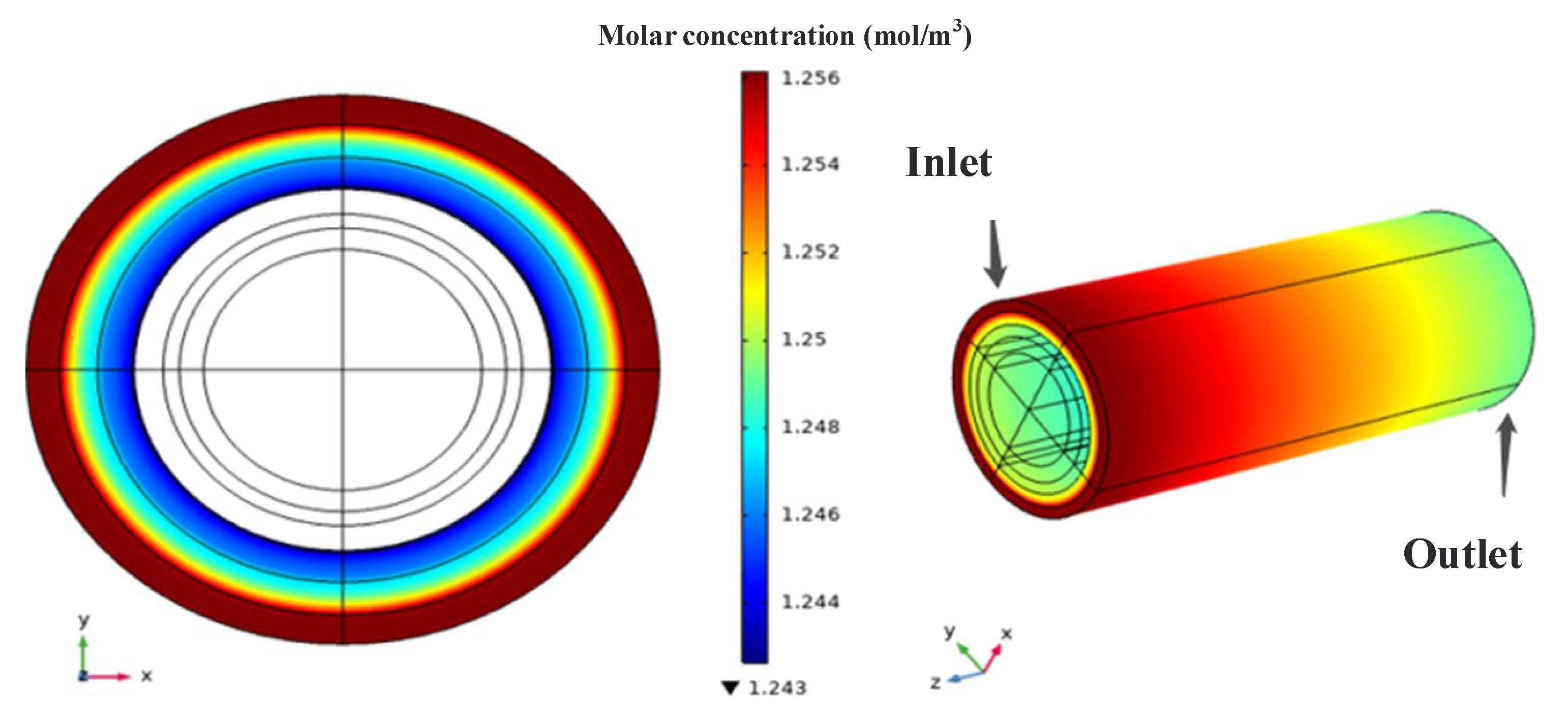
According to Figure 3, the molar concentration distribution of the reaction gases shows a decreasing trend both radially (from outer to inner) and along the flow direction. The color stratification of oxygen along the radial direction is more distinct, indicating that the consumption rate of oxygen is faster than that along the flow direction. This is mainly because the oxygen in the gas channel layer can be continuously replenished, but for oxygen to participate in the reaction at the electrolyte interface, it must diffuse through the porous resistance layer. Generally, the reaction consumption rate is greater than the diffusion rate, which leads to the gradually decreasing trend along the radial direction. In practice, insufficient oxygen participation in the reaction may result in the inability of the cell to operate.
Furthermore, it can be visually observed that the decrease in oxygen concentration is initially rapid and then slows down. The main reason for this is the change in reaction rate. According to chemical reaction kinetics theory, the reaction rate is directly proportional to the concentration of reactants. As oxygen is gradually consumed, the concentration of participating oxygen decreases, and the reaction rate slows down accordingly. The distribution of oxygen concentration is of great reference value for determining the operating performance of the cell. As mentioned earlier, in this model, oxygen is ionized at the cathode and enters the electrolyte and anode layer to participate in electrochemical reactions. Oxygen ions dominate in ion conductivity. Therefore, ensuring a sufficient oxygen supply is beneficial for improving reaction rate and ion conductivity.
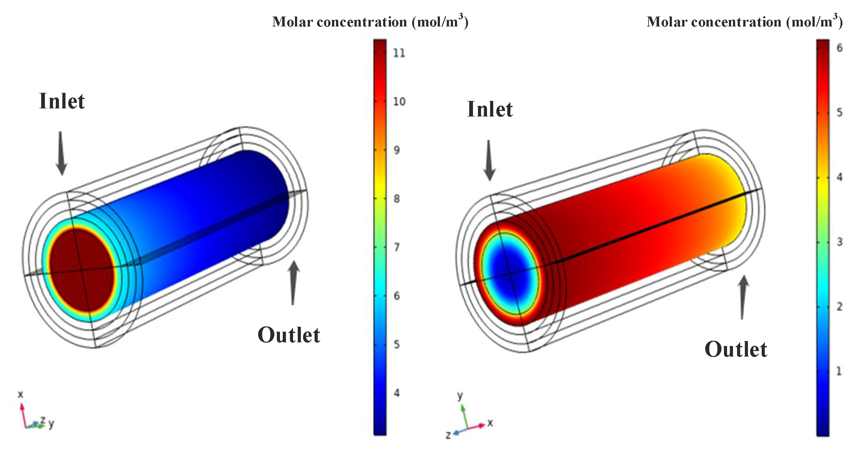
According to Figure 4, both hydrogen and ammonia show a decreasing trend in concentration whether they are distributed radially (from inside to outside) or in the flow direction. The degree of change is similar for both species, primarily because the anode of the SOFC undergoes a gradual dehydrogenation reaction when ammonia is introduced to participate in the electrochemical reaction, allowing hydrogen ions to combine with oxygen ions to generate water. This dehydrogenation reaction is not equivalent to the external reaction of decomposing hydrogen due to the high-temperature environment. Additionally, as mentioned earlier in the setup, the reactant gas contains ammonia, hydrogen, and nitrogen, so the numerical value of hydrogen concentration should be much lower than that of ammonia concentration. However, in terms of numerical values, the degree of decrease for both species is much greater than that of oxygen. This is mainly because in the SOFC, the reaction rate at the anode is faster than that at the cathode, and from a microscopic perspective, the size of oxygen molecules is larger, so their diffusion rate in the porous medium is slower. Similarly, the concentration decrease rates of ammonia and hydrogen also show a fast-to-slow trend. According to the theory of chemical reaction kinetics, their reaction rates gradually decrease as the concentration of ammonia and hydrogen decreases, which is applicable to both the cathode and anode sides.
Considering that this model belongs to an anode-supported structure, where the anode layer thickness is greater than that of the electrolyte and cathode layers, although it needs to overcome the resistance of the porous medium, it does not have a significant impact on the diffusion of hydrogen. Compared with hydrogen, the thicker anode diffusion layer can make the reactant gas obtain more uniform distribution in the anode layer, thereby improving the reaction rate at the anode. On the other hand, in the cathode layer, the thinner, porous cathode layer means that oxygen loses more opportunities to participate in the reaction due to diffusion limitations caused by its larger molecular size. This results in most of the oxygen being discharged without diffusing sufficiently towards the interior. This indirectly proves that if the amount of oxygen available for reaction is insufficient, its reaction rate with the anode does not increase, and ultimately the performance of the cell declines.

3.2. Current Density Analysis

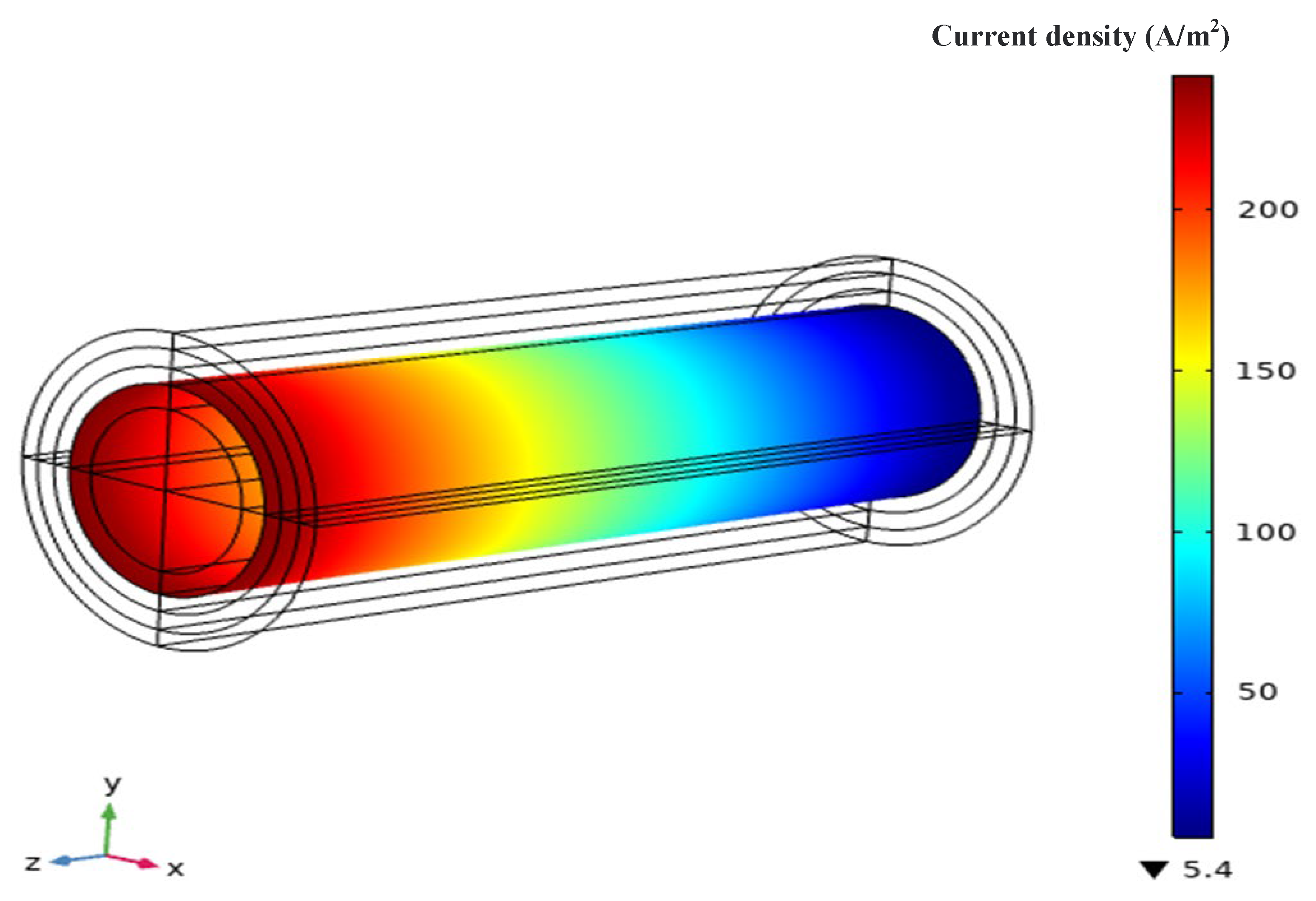
The electrolyte current density distribution of this model at a working voltage of 0.8 V is shown in Figure 5. Generally, the current density distribution of an SOFC is related to the concentration distribution of hydrogen and oxygen. The uneven distribution of current density is a result of gas consumption, and the majority of the current is generated near the cathode inlet. Comparing the gas concentration distribution analyzed in the previous section, it can be seen that the decrease in current density follows a similar trend to the concentration distribution of oxygen, with a rapid decline followed by a slower decline. At the same time, another important consideration when simulating current density results is the reaction active area at the interface between the anode and the electrolyte layer.
Due to the presence of porous media, there are usually several active points where ion conduction occurs. If these active points are not uniformly distributed, it may also lead to uneven distribution of current density. However, because this model is at the millimeter scale and only calculates the average value of local current density, the numerical discrepancy of the oxygen concentration distribution is not significant enough, and this conclusion may not be sufficiently convincing. As is well known, current density reflects the output performance and operational stability of an SOFC. For an AS-SOFC using ammonia fuel, there are two main ways to improve performance: (1) increase the inlet oxygen flow and raise the inlet temperature of the anode to obtain more hydrogen decomposition, promoting electrochemical reaction rates by increasing reactant concentrations; or (2) increase the active surface area of the reaction (reaction sites between the electrode and the electrolyte layer), promoting electronic and ionic conduction activity.

3.3. Temperature Field Analysis
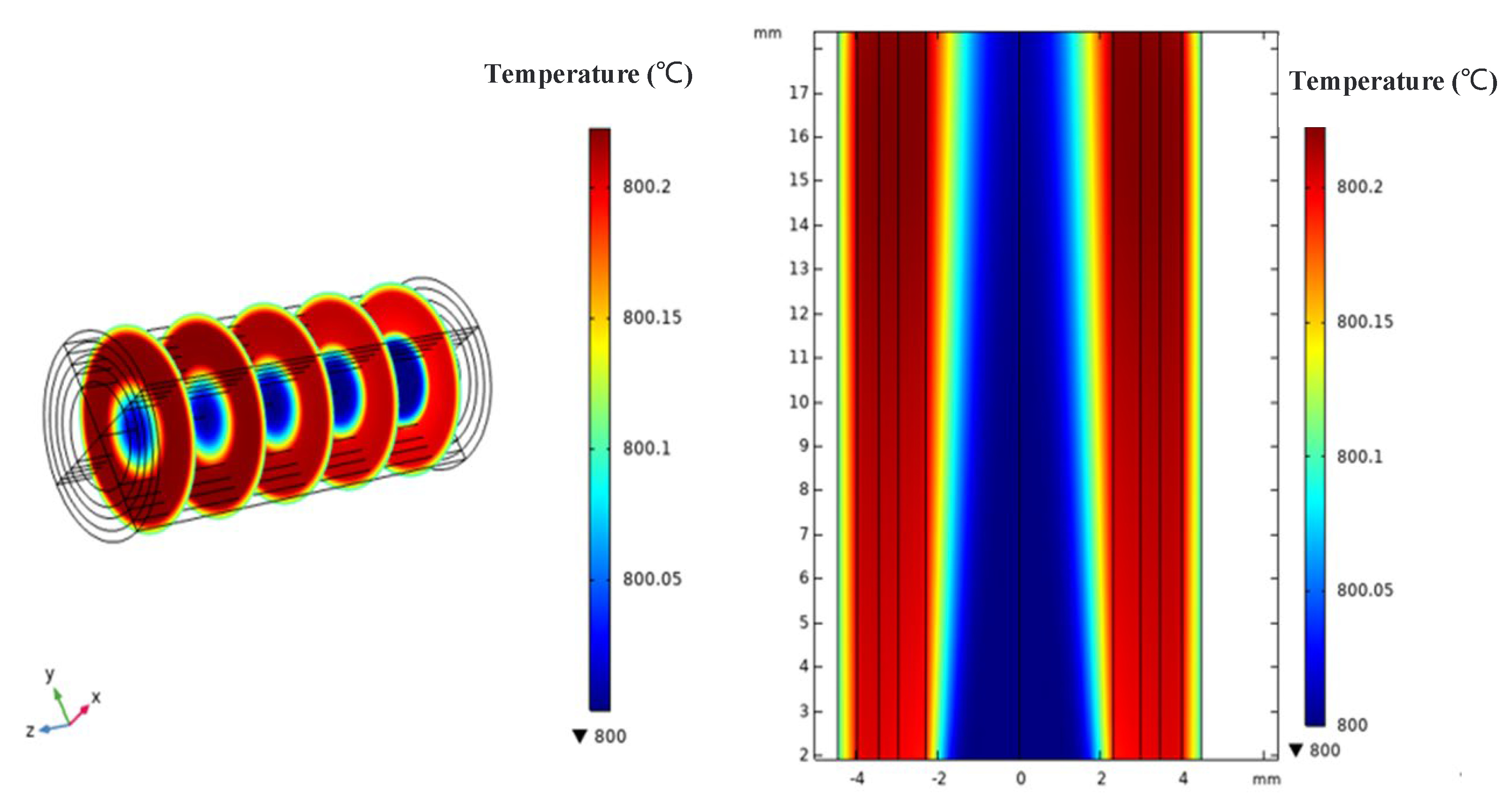
From Figure 6, it can be seen that both ammonia and air exhibit a temperature increase trend from the inlet side to the outlet side, as heat accumulates gradually during the electrochemical reactions. The temperature distribution from the fuel inlet side to the air inlet side shows an initial increase followed by a decrease, and the temperature in the reaction layer is higher than that in the flow channel layer. This is mainly due to the fact that in SOFCs, not only heat transfer occurs as fuel gas or air diffuses towards the reaction layer, but also Joule heat generated by the electrochemical reactions diffuses towards the periphery of the cell, where the heat generated by the electrochemical reactions dominates. In the heat transfer module of this AS-SOFC model, the reaction interface between the anode layer and the electrolyte layer has been set as the heat source surface, and all boundaries where reactions occur have heat flux continuity. There are no reaction interfaces where heat exchange cannot occur, and the anode layer itself is relatively thick and has good thermal conductivity. Heat can be transferred through the relatively ideal porous medium layer by conduction and convective heat transfer with the gas to the entire cell.
Research has shown that the temperature of the air in the cathode flow channel is generally increased by the heat exchange within the SOFC and is generally not directly affected by external interventions. Therefore, adjusting the airflow can also achieve the purpose of adjusting the SOFC temperature. Based on the current technological conditions, it is difficult to measure the internal temperature distribution of the cell in actual testing since the reaction region inside the tube is enclosed. Therefore, it is very meaningful to analyze the temperature distribution through numerical simulation. In this simulation analysis, the computation in the temperature field simulation was simplified, the given heat transfer coefficient and resistance values of the materials were small, and the temperature changes were not significant numerically. However, the overall trend of the temperature changes was similar to that observed in actual experiments, which indirectly demonstrates that numerical simulation can accurately analyze the temperature distribution inside the tubular cell and can replace the actual measurement method.

3.4. Performance Design

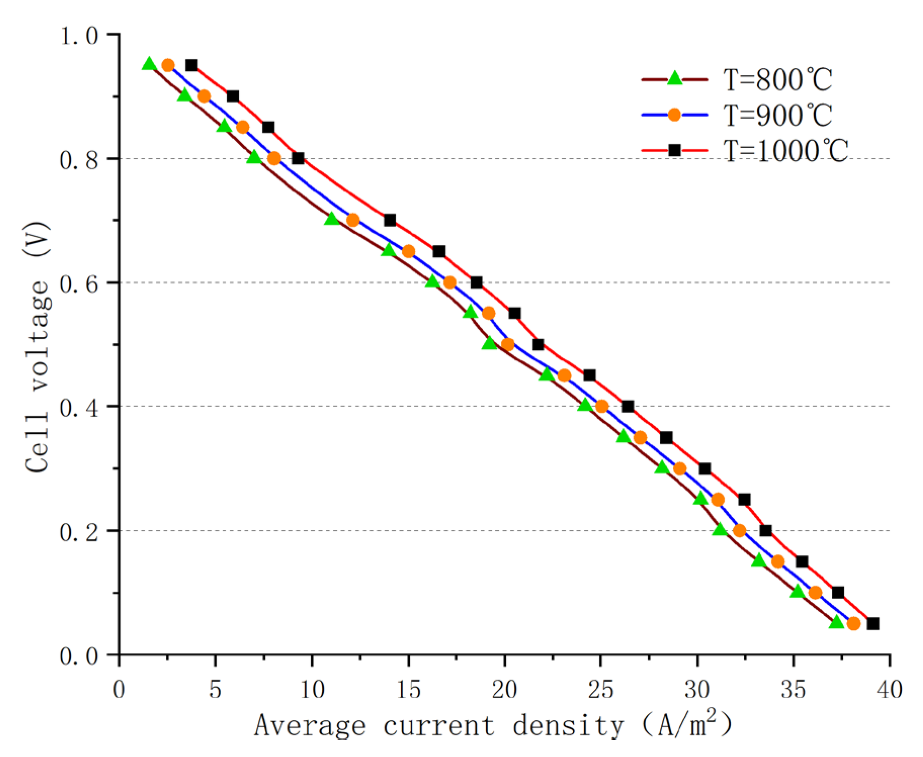
External environmental factors can have a significant impact on fuel cell performance, and one of the main factors is the temperature of the incoming gas. Figure 7 shows the polarization curve results of an AS-SOFC using ammonia fuel at operating temperatures of 800 °C, 900 °C, and 1000 °C, respectively. Although the numerical changes are not very significant, a comparison of the results indicates that, as the temperature increases, there can be a larger output current and thus higher power output for the same operating voltage. This increase in performance and stability is not limited to a single voltage range but is reflected in the overall output of the cell. This is mainly due to the enhanced conductivity of the electrolyte material at higher temperatures, the decrease in ohmic resistance, and the weakening of polarization effects. In addition, at high temperatures, more hydrogen can be released from the ammonia to produce larger amounts of hydrogen gas through decomposition. According to chemical reaction kinetics theory, the more intense diffusion motion of molecules and ions at high temperatures can promote the overall electrochemical reaction. Although increasing the temperature can enhance the performance of the fuel cell, the operating temperature of the SOFC is generally set below 1100 °C to prevent the possible occurrence of electrochemical side reactions that can disrupt the overall balance. Even solid-state electrolyte layers can undergo structural changes and deteriorate the performance of the cell at high temperatures, and current leakage can occur easily, which dramatically shortens the operating life of the SOFC. Therefore, in the process of exploring the optimal temperature conditions, the impact of temperature on the internal reactions and material characteristics of the cell must be taken into account.
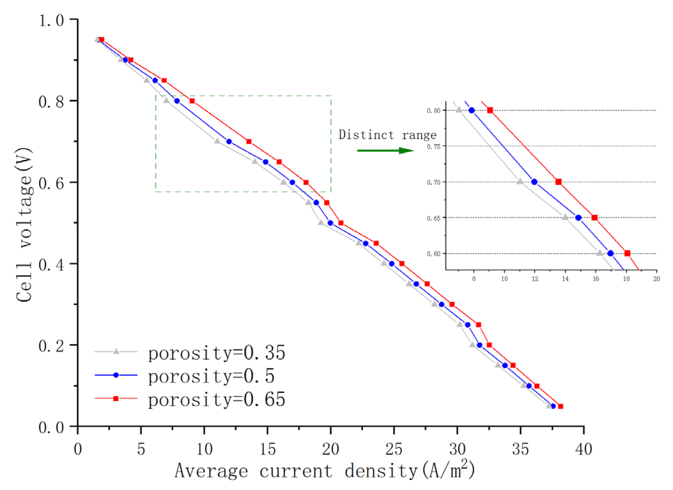
Among the various internal material properties of the cell, the porosity of the porous electrode is one of the main factors affecting fuel cell performance. Figure 8 shows the polarization curves of AS-SOFCs using ammonia fuel with a porosity of 0.35, 0.5, and 0.65, respectively. Comparative analysis of the results reveals that as porosity increases, fuel cell performance gradually improves. This is mainly because porosity affects the rate of gas diffusion. With larger porosity, gas diffusion resistance decreases, allowing more gas to quickly reach the reaction layer, thus accelerating the electrochemical reaction rate and weakening concentration polarization. However, the overall change in the numerical values is not significant, except for a relatively significant variation range in the working voltage of 0.6–0.8 V. This may be due to the strong electronic and ionic conductivity activity in this stage, resulting in a relatively weak polarization effect. Under the same porosity, it is easier to involve more gas in the electrochemical reaction. Therefore, it can be inferred that to further improve the fuel cell performance of the model by changing the porosity, it is necessary to keep the working voltage within this range. However, material properties, including porosity, should not be blindly pursued for enlargement and strengthening. Although increasing porosity optimizes fuel cell performance, excessive porosity can lead to unstable internal structure of the porous medium layer. Excessive porosity density can cause an inability to withstand gas flow pressure or to meet electrode reaction requirements. Similarly, material property parameters such as the conductivity of each layer and the viscosity coefficient of the flow channel also need to explore suitable values to optimize SOFC performance while meeting the stability requirements of the reaction.
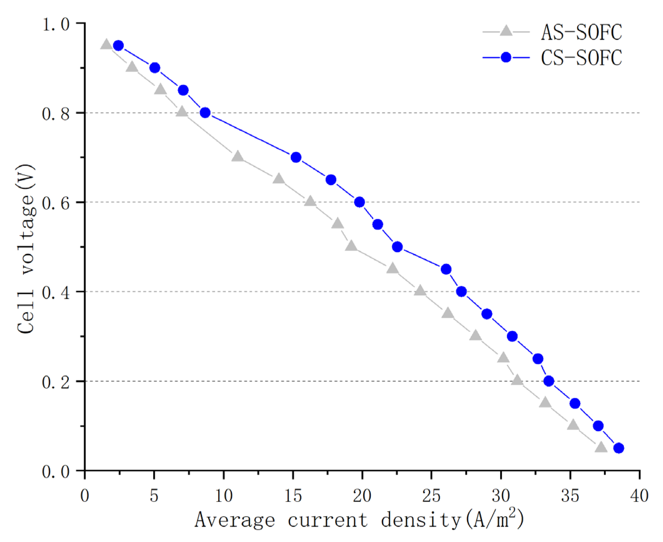
In the current mainstream SOFC designs, there are two main types of cells: AS-SOFCs and CS-SOFCs. The main difference between these two types lies in the thicker support electrode layer inside the cell. Figure 9 shows the polarization curves of the two types of cells under the same operating conditions. After a comparative analysis, it is clear that CS-SOFC performs better overall than AS-SOFC in terms of working performance, with a significantly larger numerical change than the influence of temperature and porosity. This is mainly because the primary factor affecting the current density of the electrolyte layer is the oxygen concentration distribution in the cathode layer. For CS-SOFC, the thicker cathode support layer ensures sufficient oxygen supply and high cathode gas channel sealing, which has a significant positive effect on achieving uniform current density distribution and improving the performance of output current for tubular SOFCs.
Although CS-SOFC slightly outperforms AS-SOFC in numerical simulation results, when considering working stability in practical production applications, it is not sufficient to solely consider the working performance of the fuel cell. Both AS-SOFC and CS-SOFC are three-layer (sandwich) structures, with the electrolyte inserted between the anode and cathode. The only difference between the two is the thickness of the support layer, with the anode being the thickest layer in AS-SOFC and the cathode being the thickest layer in CS-SOFC. However, achieving the internal cathode support layer of CS-SOFC is challenging due to its high sintering temperature requirement. The mechanical strength of the cathode is a concern due to its high porosity, and the thermal expansion coefficient is normally higher than that of the anode and electrolyte. Therefore, there is still considerable controversy over which type of tubular SOFC will dominate the future industrial market. Overall, further research and development are needed to determine the most suitable SOFC type for practical production applications.

4. Conclusions

This study aimed to explore the viability of utilizing an ammonia fuel tubular SOFC for shipborne UAVs. To achieve this goal, a comprehensive three-dimensional model of a tubular anode-supported SOFC single cell was developed, which incorporated the necessary mathematical models for its structure and operation principles. To enhance the precision of the model, multiphysics fields were taken into account, and numerical simulations of the SOFC’s working conditions under ammonia fuel were conducted. Through the simulations, several performance indicators were calculated and analyzed to determine the effects of different operating conditions on the SOFC’s performance. To optimize the SOFC’s performance, the paper employed the method of controlling variables to adjust the working parameters and overall structure of the cell. Through this optimization analysis, the factors that significantly impact cell performance were identified, which can guide future improvements in SOFC design and operation.
The study’s results indicate that increasing the temperature of the SOFC enhances battery performance due to the facilitation of ammonia fuel dehydrogenation and improved rates of electrochemical reactions, electron, and ion conductivity. However, operating temperatures above 1100 °C can cause electrode microstructural deformation and electrochemical side reactions, leading to a decline in battery performance. In addition, increasing porosity can enhance battery performance due to reduced gas flow resistance, higher concentration of reaction gas, and reduced concentration polarization. A significant performance improvement was observed in the range of 0.6–0.8 V due to strong electron and ion conductivity and weak polarization effects. Nevertheless, excessive porosity can cause instability in the electrode layer structure.
Moreover, CS-SOFC showed improved performance compared to AS-SOFC mainly because of its thicker cathode layer, which provides sufficient oxygen supply and better sealing, resulting in more uniform current density distribution. However, AS-SOFC has greater practicality in practical production than CS-SOFC, and both have significant potential for development.
The findings of this study offer valuable insights into the potential application of ammonia fuel for shipborne UAVs and provide a foundation for future research and development in the field of SOFCs.

Author Contributions

Conceptualization, Z.W. and F.H.; methodology, F.Z.; software, F.Z.; validation, Y.M., R.X.; formal analysis, Y.M., R.X.; investigation, Y.M., R.X.; resources, F.Z.; data curation, F.Z.; writing—original draft preparation, Z.W.; writing—review and editing, F.H.; visualization, F.Z.; supervision, F.H.; project administration, F.H.; funding acquisition, F.H. All authors have read and agreed to the published version of the manuscript.

Funding

This work was supported by the Fundamental Research Funds for the Central Universities (3132023510), the Open Fund of National Center for International Research of Subsea Engineering Technology and Equipment (No. 3132023358), the CNOOC Marine Environment and Ecological Protection Public Welfare Foundation Project (CF-MEEC/TR/2023-9), the Dalian High Level Talent Innovation Support Program (2021RQ132), the Natural Science Foundation of Liaoning Province (2022-MS-154), the China Postdoctoral Science Foundation (2020M680928), and the 111 Project (B18009).

Data Availability Statement

Not applicable.

Conflicts of Interest

The authors declare no conflict of interest.

Nomenclature

CpEquivalent specific heat capacity
DDiffusion coefficient
EaReaction activation energy
ETheoretical Nernst voltage (V)
FVolume force
hHeat transfer coefficient (W·m−2·K−1)
LHeat transfer length (mm)
kThermal conductivity (W·m−1·K−1)
vGas velocity (m·s−1)
MMolar molecular weight
ΔPPressure drop (kPa)
PrPrandtl number
qHeat (W)
QHeat flux (W)
ReReynolds number
SiThermal diffusion constant
TTemperature (K)
UOverall heat transfer coefficient (W·m−2·K−1)
vSpecific volume (m3·kg−1)
PwPump power (kW)
μDynamic viscosity (Pa·s)
uVelocity (m·s−1)
Greek symbols
μViscosity coefficient
ρDensity (kg·m−3)
ηactActivation polarization loss
ηconcConcentration polarization loss
ηohmOhmic polarization loss
φgPorosity of the porous media
Subscripts
0Standard or parameter at equilibrium conditions
refReference value
kCoordinate variable
x, y, zDirections
i, oInlet or outlet
Abbreviations
AS-SOFCAnode-supported solid oxide fuel cell
CS-SOFCCathode-supported solid oxide fuel cell
ICEsInternal combustion engines
SOFCSolid oxide fuel cells
UAVsUnmanned aerial vehicles

References

  1. Onifade, S.T.; Alola, A.A. Energy transition and environmental quality prospects in leading emerging economies: The role of environmental-related technological innovation. Sustain. Dev. 2022, 30, 1766–1778. [Google Scholar] [CrossRef]
  2. Deng, Z.; Bing, F.; Guo, Z.; Wu, L. Rope-Hook Recovery Controller Designed for a Flying-Wing UAV. Aerospace 2021, 8, 384. [Google Scholar] [CrossRef]
  3. Cipolla, V.; Dine, A.; Viti, A.; Binante, V. MDAO and Aeroelastic Analyses of Small Solar-Powered UAVs with Box-Wing and Tandem-Wing Architectures. Aerospace 2023, 10, 105. [Google Scholar] [CrossRef]
  4. Zappa, C.J.; Brown, S.M.; Laxague, N.J.; Dhakal, T.; Harris, R.A.; Farber, A.M.; Subramaniam, A. Using ship-deployed high-endurance unmanned aerial vehicles for the study of ocean surface and atmospheric boundary layer processes. Front. Mar. Sci. 2020, 6, 777. [Google Scholar] [CrossRef]
  5. Olabi, A.G.; Abdelkareem, M.A.; Wilberforce, T.; Alkhalidi, A.; Salameh, T.; Abo-Khalil, A.G.; Hassan, M.M.; Sayed, E.T. Battery electric vehicles: Progress, power electronic converters, strength (S), weakness (W), opportunity (O), and threats (T). Int. J. 2022, 16, 100212. [Google Scholar] [CrossRef]
  6. Micallef, A.; Guerrero, J.M.; Vasquez, J.C. New Horizons for Microgrids: From Rural Electrification to Space Applications. Energies 2023, 16, 1966. [Google Scholar] [CrossRef]
  7. Liu, F.; Ding, D.; Duan, C. Protonic Ceramic Electrochemical Cells for Synthesizing Sustainable Chemicals and Fuels. Adv. Sci. 2023, 10, 2206478. [Google Scholar] [CrossRef] [PubMed]
  8. Liu, F.; Diercks, D.; Hussain, A.M.; Dale, N.; Furuya, Y.; Miura, Y.; Fukuyama, Y.; Duan, C. Nanocomposite Catalyst for High-Performance and Durable Intermediate-Temperature Methane-Fueled Metal-Supported Solid Oxide Fuel Cells. ACS Appl. Mater. Interfaces 2022, 14, 53840–53849. [Google Scholar] [CrossRef]
  9. Tawalbeh, M.; Murtaza, S.Z.; Al-Othman, A.; Alami, A.H.; Singh, K.; Olabi, A.G. Ammonia: A versatile candidate for the use in energy storage systems. Renew. Energy 2022, 194, 955–977. [Google Scholar]
  10. Rony, Z.I.; Mofijur, M.; Hasan, M.M.; Rasul, M.G.; Jahirul, M.I.; Ahmed, S.F.; Kalam, M.A.; Badruddin, I.A.; Khan, T.Y.; Show, P.L. Alternative fuels to reduce greenhouse gas emissions from marine transport and promote UN sustainable development goals. Fuel 2023, 338, 127220. [Google Scholar] [CrossRef]
  11. Lei, T.; Min, Z.; Gao, Q.; Song, L.; Zhang, X.; Zhang, X. The Architecture Optimization and Energy Management Technology of Aircraft Power Systems: A Review and Future Trends. Energies 2022, 15, 4109. [Google Scholar] [CrossRef]
  12. Çelik, D.; Meral, M.E.; Waseem, M. Investigation and analysis of effective approaches, opportunities, bottlenecks and future potential capabilities for digitalization of energy systems and sustainable development goals. Electr. Power Syst. Res. 2022, 211, 108251. [Google Scholar] [CrossRef]
  13. Feng, Y.; Qu, J.; Zhu, Y.; Wu, B.; Wu, Y.; Xiao, Z.; Liu, J. Progress and prospect of the novel integrated SOFC-ICE hybrid power system: System design, mass and heat integration, system optimization and techno-economic analysis. Energy Convers. Manag. X 2023, 18, 100350. [Google Scholar] [CrossRef]
  14. Ma, Y.; Wang, Z.; Yu, S.; Han, F.; Ji, Y.; Cai, W. Design and Simulation of Ammonia-Fueled SOFC-ICE Hybrid Power System for Ship Application. In Proceedings of the 2022 7th International Conference on Power and Renewable Energy (ICPRE), Shanghai, China, 23–26 September 2022; IEEE: New York, NY, USA, 2022; pp. 772–777. [Google Scholar]
  15. Wu, S.; Miao, B.; Chan, S.H. Feasibility assessment of a container ship applying ammonia cracker-integrated solid oxide fuel cell technology. Int. J. Hydrog. Energy 2022, 47, 27166–27176. [Google Scholar] [CrossRef]
  16. Xu, Q.; Guo, Z.; Xia, L.; He, Q.; Li, Z.; Bello, I.T.; Zheng, K.; Ni, M. A comprehensive review of solid oxide fuel cells operating on various promising alternative fuels. Energy Convers. Manag. 2022, 253, 115175. [Google Scholar]
  17. Qureshi, F.; Yusuf, M.; Kamyab, H.; Vo, D.-V.N.; Chelliapan, S.; Joo, S.-W.; Vasseghian, Y. Latest eco-friendly avenues on hydrogen production towards a circular bioeconomy: Currents challenges, innovative insights, and future perspectives. Renew. Sustain. Energy Rev. 2022, 168, 112916. [Google Scholar] [CrossRef]
  18. Qureshi, F.; Yusuf, M.; Kamyab, H.; Zaidi, S.; Khalil, M.J.; Khan, M.A.; Alam, M.A.; Masood, F.; Bazli, L.; Chelliapan, S.; et al. Current trends in hydrogen production, storage and applications in India: A review. Sustain. Energy Technol. Assess. 2022, 53, 102677. [Google Scholar] [CrossRef]
  19. Sonker, M.; Tiwary, S.K.; Shreyash, N.; Bajpai, S.; Ray, M.; Kar, S.K.; Balathanigaimani, M. Ammonia as an alternative fuel for vehicular applications: Paving the way for adsorbed ammonia and direct ammonia fuel cells. J. Clean. Prod. 2022, 376, 133960. [Google Scholar] [CrossRef]
  20. Ashrafi, M.; Lister, J.; Gillen, D. Toward a harmonization of sustainability criteria for alternative marine fuels. Marit. Transp. Res. 2022, 3, 100052. [Google Scholar] [CrossRef]
  21. Hollmann, J.; Fuchs, M.; Spieker, C.; Gardemann, U.; Steffen, M.; Luo, X.; Kabelac, S. System simulation and analysis of an LNG-fueled SOFC system using additively manufactured high temperature heat exchangers. Energies 2022, 15, 941. [Google Scholar] [CrossRef]
  22. Wu, Z.; Zhu, P.; Yao, J.; Abu Mansor, M.R.; Chen, J.; Huang, S.-M. Design of novel flow channels of tubular biomass-syngas fueled SOFC towards uniform temperature distribution. Sustain. Energy Technol. Assess. 2023, 55, 102947. [Google Scholar] [CrossRef]
  23. Raza, T.; Yang, J.; Wang, R.; Xia, C.; Raza, R.; Zhu, B.; Yun, S. Recent advance in physical description and material development for single component SOFC: A mini-review. Chem. Eng. J. 2022, 444, 136533. [Google Scholar] [CrossRef]
  24. Yang, Z.; Yu, X.; Dedman, S.; Rosso, M.; Zhu, J.; Yang, J.; Xia, Y.; Tian, Y.; Zhang, G.; Wang, J. UAV remote sensing applications in marine monitoring: Knowledge visualization and review. Sci. Total Environ. 2022, 838, 155939. [Google Scholar] [CrossRef]
  25. Tran, T.L.C.; Huang, Z.C.; Tseng, K.H.; Chou, P.H. Detection of Bottle Marine Debris Using Unmanned Aerial Vehicles and Machine Learning Techniques. Drones 2022, 6, 401. [Google Scholar] [CrossRef]
  26. Wang, X.; Zhu, J.; Han, M. Industrial Development Status and Prospects of the Marine Fuel Cell: A Review. J. Mar. Sci. Eng. 2023, 11, 238. [Google Scholar] [CrossRef]
  27. Benet, Á.; Villalba-Herreros, A.; D’amore-Domenech, R.; Leo, T.J. Knowledge gaps in fuel cell-based maritime hybrid power plants and alternative fuels. J. Power Sources 2022, 548, 232066. [Google Scholar] [CrossRef]
  28. Marciello, V.; Di Stasio, M.; Ruocco, M.; Trifari, V.; Nicolosi, F.; Meindl, M.; Lemoine, B.; Caliandro, P. Design Exploration for Sustainable Regional Hybrid-Electric Aircraft: A Study Based on Technology Forecasts. Aerospace 2023, 10, 165. [Google Scholar] [CrossRef]
  29. Choi, Y.; Lee, J. Estimation of Liquid Hydrogen Fuels in Aviation. Aerospace 2022, 9, 564. [Google Scholar] [CrossRef]
  30. Ilbas, M.; Kumuk, B.; Alemu, M.A.; Arslan, B. Numerical investigation of a direct ammonia tubular solid oxide fuel cell in comparison with hydrogen. Int. J. Hydrog. Energy 2020, 45, 35108–35117. [Google Scholar]
  31. Barelli, L.; Bidini, G.; Cinti, G. Operation of a Solid Oxide Fuel Cell Based Power System with Ammonia as a Fuel: Experimental Test and System Design. Energies 2020, 13, 6173. [Google Scholar] [CrossRef]
  32. Khodabandeh, E.; Akbari, O.A.; Akbari, S.; Taghizadeh, A.; Pour, M.S.; Ersson, M.; Jönsson, P.G. The effects of oil/MWCNT nanofluids and geometries on the solid oxide fuel cell cooling systems: A CFD study. J. Therm. Anal. Calorim. 2021, 144, 245–256. [Google Scholar] [CrossRef]
  33. Rathore, S.S.; Biswas, S.; Fini, D.; Kulkarni, A.P.; Giddey, S. Direct ammonia solid-oxide fuel cells: A review of progress and prospects. Int. J. Hydrog. Energy 2021, 46, 35365–35384. [Google Scholar] [CrossRef]
  34. Farhad, S.; Hamdullahpur, F. Conceptual design of a novel ammonia-fuelled portable solid oxide fuel cell system. J. Power Sources 2010, 195, 3084–3090. [Google Scholar] [CrossRef]
  35. Chaudhary, T.N.; Mehmood, M.; Saleem, U.; Abbasi, M.S.; Chen, B. Modeling of thermal impacts in a single direct methane steam reforming solid oxide fuel cell. J. Power Sources 2020, 472, 228605. [Google Scholar] [CrossRef]
  36. Buttler, A.; Koltun, R.; Wolf, R.; Spliethoff, H. A detailed techno-economic analysis of heat integration in high temperature electrolysis for efficient hydrogen production. Int. J. Hydrog. Energy 2015, 40, 38–50. [Google Scholar] [CrossRef]
  37. Kishimoto, M.; Kume, T.; Iwai, H.; Yoshida, H. Numerical analysis of ammonia-fueled planar solid oxide fuel cells. ECS Trans. 2017, 78, 2845. [Google Scholar] [CrossRef]
  38. Kee, R.J.; Zhu, H.; Sukeshini, A.M.; Jackson, G.S. Solid oxide fuel cells: Operating principles, current challenges, and the role of syngas. Combust. Sci. Technol. 2008, 180, 1207–1244. [Google Scholar] [CrossRef]
  39. Tan, W.Y. Numerical simulation on the performance of a solid oxide fuel cell with direct ammonia internal decomposition. Energy Sources Part A Recovery Util. Environ. Eff. 2014, 36, 2410–2419. [Google Scholar] [CrossRef]
  40. Hajimolana, S.A.; Hussain, M.A.; Daud, W.W.; Chakrabarti, M.H. Dynamic modelling and sensitivity analysis of a tubular SOFC fuelled with NH3 as a possible replacement for H2. Chem. Eng. Res. Des. 2012, 90, 1871–1882. [Google Scholar] [CrossRef]
  41. COMSOL Multiphysics, Version 6. COMSOL Inc.: Burlington, MA, USA. Available online: https://www.comsol.com (accessed on 1 March 2023).
  42. Lai, Y.; Wang, Z.; Cui, D.; Han, F.; Ji, Y.; Cai, W. Thermal impact performance study for the thermal management of ammonia-fueled single tubular solid oxide fuel cell. Int. J. Hydrog. Energy 2023, 48, 2351–2367. [Google Scholar] [CrossRef]
  43. Wang, Y.; Gu, Y.; Zhang, H.; Yang, J.; Wang, J.; Guan, W.; Chen, J.; Chi, B.; Jia, L.; Muroyama, H.; et al. Efficient and durable ammonia power generation by symmetric flat-tube solid oxide fuel cells. Appl. Energy 2020, 270, 115185. [Google Scholar] [CrossRef]
Figure 1. Geometric structure diagram of SOFC monomer.
Aerospace 10 00397 g001
Figure 2. Comparison between experimental data [30] and simulation results.
Aerospace 10 00397 g002
Figure 3. Oxygen molar concentration distribution.
Aerospace 10 00397 g003
Figure 4. Ammonia and hydrogen fuels molar concentration distribution.
Aerospace 10 00397 g004
Figure 5. Electrolyte current density distribution.
Aerospace 10 00397 g005
Figure 6. Temperature field distribution.
Aerospace 10 00397 g006
Figure 7. Polarization curves at different operating temperatures.
Aerospace 10 00397 g007
Figure 8. Polarization curves under different porosity.
Aerospace 10 00397 g008
Figure 9. Polarization curves of anodic and cathodic SOFCs.
Aerospace 10 00397 g009
Table 1. SOFC geometry dimensions in UAVs [30,42].
ItemsUnitsValue
Inner diameter of ammonia fuel runner layermm4.62
Anode diffusion layer thicknessmm0.78
Electrolyte layer thicknessmm0.45
Cathode diffusion layer thicknessmm0.32
Air layer thicknessmm0.51
Pipe rangemm20.00
Table 2. Main working parameters [30,37,42,43].
ItemsUnitsValue
Initial polarization voltageV0.05
Anode equilibrium voltageV0
Cathode balance voltageV0.8
Anode exchange current densityA/m21
Cathode exchange current densityA/m20.1
Anode layer conductivityS/m10
Cathode layer conductivityS/m10
Conductivity of electrolyte layerS/m5
Anodic permeabilitym21 × 10−10
Cathode permeabilitym21 × 10−10
Porosity0.35
Cathode surface area ratiom−12.8 × 10⁴
Anode flow path viscosityPa·s1.19 × 10−5
Anode surface area ratiom−12.2 × 10⁴
Viscosity of cathode flow pathPa·s2.46 × 10−5
Air inlet velocitym/s1
Intake inlet temperatureK1073.15
Operating pressureatm1
Reference diffusion coefficientm2/s3.2×10−8
Disclaimer/Publisher’s Note: The statements, opinions and data contained in all publications are solely those of the individual author(s) and contributor(s) and not of MDPI and/or the editor(s). MDPI and/or the editor(s) disclaim responsibility for any injury to people or property resulting from any ideas, methods, instructions or products referred to in the content.

