Abstract
To determine the dynamic characteristics of a gas-centered swirl coaxial injector under backpressure, an experimental system of dynamic injection in a backpressure chamber was constructed. Filtered water and nitrogen were used as simulant media for rocket propellants, which are typically used with this kind of injector. An inertial flow pulsator was manufactured to generate the pulsation of the flows that feed to the liquid injector. The electric conductance method was adopted to measure liquid film thickness. After the pulsation of incoming flow in the feedline was tested, and the operating conditions for the injector to start pulsating were validated, the effects of the chamber backpressure and the recess length of the injector on the dynamic characteristics of spray, such as liquid film thickness, breakup length, and amplitude of pulsation, have been investigated in detail. Experimental results demonstrated that the increase in chamber backpressure prompts the liquid sheet to rupture earlier with a shorter breakup length, which results from the increased density of the ambient gas. Chamber backpressure suppresses the pulsation of the outlet flow, especially for a longer recess length. Moreover, a decrease in the recess length results in a reduction in breakup length due to an intense gas–liquid shearing in a narrower recess section. For a lower backpressure, the amplitude of outlet flow generally increases when the recess length increases. However, this phenomenon is not obvious for the conditions of higher backpressure and lower pulsation frequency.
1. Introduction
The gas-centered swirl coaxial (GCSC) injectors are widely used in the combustion chamber of liquid rocket engines, such as NK-33, RD180, YF-100, and YF-115 [1]. In the combustion chamber, the GCSC injector ejects the liquid fuel that encloses the oxygen-rich gas in the middle [2,3,4]. The use case of this is typically the staged combustion cycle engines. One propellant is burned with a small amount of the other in the preburner, producing a hot gas mixture. Then, this gas mixture (oxygen-rich gas) passes through the turbine and is injected into the thrust chamber [2]. Under the action of gas–liquid shear force and centrifugal force, the conical liquid sheet breaks up and is atomized into liquid filaments and droplets. Further, the propellant burns in the chamber. However, liquid rocket engines often encounter the challenge of unstable combustion, which can be devastating to the combustion chamber. With a better understanding of the unstable combustion problem, it has been found that the dynamic characteristics of the injector play an important role in the stable operation of liquid rocket engines [5]. The injector not only performs the task of spraying and mixing, but also acts as an amplifier, phase regulator, exciter, and oscillator in the overall dynamic system of the engine. Whether it is the pressure/flow pulsation from the supply system or the backpressure pulsation in the combustion chamber, the dynamic characteristics of the injector can be adjusted to cut off the instability coupling between them [6]. Therefore, it is important to study the dynamic response characteristics of the injector to the incoming pressure/flow oscillation when the chamber backpressure varies.
In recent years, there have been many experimental and theoretical studies on injection dynamics, especially on swirl injectors, single-component injectors, and dual-component coaxial injectors [2,7,8,9,10]. Bazarov [11] pioneered the work on injector dynamics. The injector frequency characteristic equation was derived analytically by using the inviscid hydrodynamic equation that controls the internal flow of the injector. After that, a detailed study of different injectors and propellants was carried out to derive the relationship between the amplitude and phase difference of each output parameter, and to describe in detail the engineering calculation method of injector dynamic characteristics [12,13,14,15,16]. More relevant to this paper is the study of the dynamic characteristics of GCSC injectors. Park et al. [17] performed a study on the dynamic characteristics of the GCSC injectors by inducing excitation on the liquid flow through a mechanical pulsator. The influence of the geometry structure (tangential inlet diameter and gap thickness) and the momentum flux ratio on the dynamic gains and the spray performance were investigated in detail. In addition to adding perturbation to the liquid flow, they also added acoustic excitation in the gas flow of the GCSC injector by a speaker [18]. The excitation effect is enhanced by the increment of the momentum flux ratio. Additionally, the spray patterns have different shapes depending on the excitation frequency. Similarly, Sahoo and Gadgil [19] experimentally studied the self-pulsation dynamics in a GCSC injector by varying the momentum flux ratio for different values of swirl number, recess length, and lip thickness. They pointed out that the constrained shear layer instability between the liquid and the gas streams inside the recess region, the spread rate of the gas jet, and its interaction location with the liquid stream dictate the presence of dominant pulsation frequencies and even their higher harmonics in many recessed configurations. The dynamic characteristics of GCSC injectors with different tangential inlet diameters were investigated by Oh et al. [20]. A mechanical pulsating flow generator was used to generate excitation in the supply line. They concluded that as the tangential inlet diameter increases, the mass flow rate increases and the spray cone angle decrease. As the tangential inlet diameter decreases, the injector becomes less effective as an amplifier, confirming that a sufficiently small tangential inlet can be used as a damper. The above studies on the dynamic characteristics and pulsating spray of the GCSC injector were conducted under the atmospheric pressure, and hardly involved the case of GCSC injectors in the combustion chamber under high backpressure conditions.
Up to now, a number of scholars have attempted to study the steady-state sprays and their mechanisms using various types of injectors under ambient pressure conditions [21,22,23,24,25,26]. To investigate the spray under high backpressure similar to a real rocket engine, the most critical thing is to build a backpressure chamber. Kenny et al. [27] fabricated a backpressure chamber that could reach 9.65 MPa. The spray experiments using a liquid swirl injector showed that an increase in the backpressure of the chamber increased the average liquid film thickness of the nozzle and made the spray cone angle smaller when the mass flow rate was constant. Kim [23] used a liquid–liquid swirl coaxial injector to perform spray experiments under high backpressure conditions and concluded that the aerodynamic force of ambient gas significantly affects the breakup of a swirl spray. However, the breakup mechanism of liquid–liquid swirl coaxial spray is very much controlled by the impact force by the interaction of propellants. Cho et al. [28] used the backpressure chamber to investigate the characteristics of a cryogenic swirl flow in a liquid swirl injector at subcritical to supercritical conditions. It is shown that the cryogenic flow behavior changes significantly when the environmental conditions change from subcritical to supercritical conditions. The interface initially produces spiral waves and then develops into a coiled vortex structure. However, the frequency of flow instability does not change dramatically during the transition from subcritical to supercritical conditions. For a liquid-centered swirl coaxial injector, Bai et al. [21] explored the self-pulsation characteristics under various chamber backpressures. As the backpressure increased, the flow in injector changed from the outer mixing flow to the critical mixing flow, and finally developed into the inner mixing flow. Moreover, for a gas–liquid swirl coaxial under backpressure, Chen et al. [29] summarized the effects of the gas–liquid ratio and ambient pressure on the spatial distribution of the spray. They concluded that the Sauter mean diameter increased with an increase in backpressure. An increase in the gas–liquid ratio caused a significant increase in the axial velocity near the axis of the spray filed. The above studies on the spray of various single-component and dual-component injectors under backpressure mainly focus on the effects of ambient backpressure, operating conditions, and geometry structure on the steady-state characteristics of the spray and its mechanism. However, few have dealt with the dynamic characteristics of the injectors under backpressure conditions.
In summary, for the various types of injectors used in liquid rocket engines, researchers have mainly focused on two aspects of the spray: the injector dynamic characteristics at atmospheric pressure and the steady-state characteristics under backpressure conditions. However, for the GCSC injector, few studies have been conducted on the dynamic characteristics under backpressure conditions. This can provide technical guidance for suppressing the combustion instability in the combustion chamber. Therefore, the present paper aimed to experimentally study the spray dynamic characteristics of the GCSC injector under various chamber backpressures. An inertial flow pulsator was manufactured to generate the dynamic pulsation of the coming flow in the liquid feedline. The liquid film thickness was measured by electric conductance method. An experimental system of dynamic injection with a backpressure chamber was constructed. The effects of the chamber backpressure and the recess length of the injector on the dynamic characteristics of spray, such as liquid film thickness, breakup length, and amplitude characteristics of pulsation, have been investigated in detail. The experimental results can help researchers to obtain some insights into the mechanism of the dynamic characteristics of the spray on the combustion instability.
2. Experimental Methods
2.1. Experimental Facilities
As depicted in Figure 1, the experimental apparatus of injector dynamics characteristics in this study consists of a supply system of simulated propellant, an excitation system of pulsating flow, a measuring system, and a backpressure environment system. When using a pump to supply liquid to the injector, a vibration along the feedline will be generated and interfere with the flow/pressure pulsation that feeds to the injector, so the pressurized water supply method is adopted. The nitrogen gas in the high-pressure nitrogen tank 2 is supplied to the working medium storage tank 1 after decompression through relief valve 17. Filtered water enters the main feedline under the squeeze of nitrogen and passes through the liquid flow meter 5. After the water flows through the flow pulsation generator 6, the flow and pressure oscillations propagating downstream will be generated. The gas feedline of injector uses nitrogen as the supply medium, which is provided by the high-pressure nitrogen tank 3 in Figure 1. A gas flow controller 4 is used to control the flow rate of the nitrogen gas.
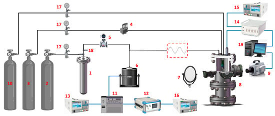
Figure 1.
Experimental facilities and setup: 1—working medium storage tank; 2, 3, 10—high-pressure nitrogen tank; 4—gas flow controller; 5—liquid flow meter; 6—flow pulsation generator; 7—LED lamp; 8—backpressure chamber; 9—high-speed camera; 11—power amplifier; 12—signal generator; 13, 15, 16—DC power supply; 14—data acquisitor; 17—relief valve; 18—stop valve; 19—computer.
The spray field information is captured using a high-speed camera 9 through the observation window of backpressure chamber 8. The pressure and flow signals in injector are measured using a dynamic pressure transducer and a homemade liquid film thickness sensor. The signals are displayed in real time through the data acquisitor 14 and stored in the computer 19. The high-pressure nitrogen tank 10 is used to inflate the backpressure chamber 8 to provide a certain ambient pressure. The mist droplets generated during the spraying process will splash on the surface of the observation window, affecting the photographic performance of the high-speed camera 9. Therefore, the observation window is purged with an air curtain using the high-pressure nitrogen tank 10.
The schematic of the GCSC injector is presented in Figure 2. The gas is injected from the injector housing into the cylindrical passage of the gas injector. The outer liquid injector is designed as an open-end swirl structure, which adopts two tangential passages that are located every 180°. The liquid in the cavity between the liquid injector and the injector housing is injected into the annular aperture between the liquid injector and the gas injector through the tangential passages. In this way, annular liquid film with swirl motion is formed. The conical liquid sheet at the injector exit is broken and atomized by centrifugal effect and aerodynamic force. The injector recess length represents the distance between the gas injector outlet and the liquid injector outlet. To investigate the effect of recess length on the injector dynamic characteristics, three GCSC injectors with different geometrical parameters were manufactured, in which the recess lengths are 13 mm, 8 mm, and 3 mm, respectively. The other structure and parameters of the injectors were determined by referring to a previous study [10] and considering the injection conditions in present experiments. The key geometrical parameters are listed in Table 1.
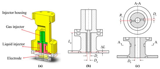
Figure 2.
Schematic of GCSC injector: (a) assembly diagram with measurement electrodes; (b) gas injector; (c) liquid injector.

Table 1.
Geometrical parameters of the GCSC injector.
The core equipment of the backpressure environment system is the backpressure chamber that is shown in Figure 3. The material of this backpressure chamber is 0Cr18Ni9 (austenitic stainless steel). It has a height of 726 mm and an inner diameter of 154 mm. The maximum ambient pressure that this chamber can withstand is 3 MPa, and the backpressure fluctuation range is ±5%. It has three optical observation windows in two perpendicular directions, which have gas purge functions. A regulator valve is installed at the bottom for regulating the chamber pressure and exhausting. It can provide backpressure experimental conditions for gas and liquid multi-component injectors.
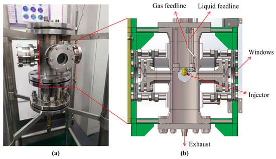
Figure 3.
Backpressure chamber: (a) physical picture; (b) internal schematic.
2.2. Experimental Conditions
The experimental conditions are summarized in Table 2. Because of the relatively simple structure and the stable operating performance, liquid swirl (LS) injector is used to calibrate the measuring system of liquid film thickness (Test 1) and test the inertial flow pulsator (Test 2–4). Test 5 is used to explore the appropriate operating condition for GCSC injector when a flow perturbation is applied into the liquid feedline by turning on the inertial flow pulsator. Exp 1–3 are designed to study the effect of the backpressure value Pb and the recess length on the dynamic characteristics of GCSC injectors, in which the pressure drop in liquid feedline and the volume flow rate Qg of gaseous nitrogen remain constant. The deviation of the pressure drops in liquid feedline and the volume flow rate of gas in these experiments did not exceed 6% and 8%, respectively.

Table 2.
Experimental conditions and parameters.
2.3. Experimental Techniques
The dynamic spray patterns were captured instantaneously by a backlighting photography technique. As depicted in Figure 1, a high-speed camera (Photron Fastcam SA-Z, Tokyo, Japan) and a surface LED lamp (Falcon Eyes SO-48TD, Hong Kong, China) were placed opposite to each other on both sides of the observation window of the backpressure chamber. The camera exposure time was set to 20 μs, and the instantaneous gray spray images with 1024 × 688 pixels were obtained. The frame rate was set to be 20,000 frames/s as the best compromise for all experiments.
Considering that the frequency of the dynamic characteristics of the injector is 10–1000 Hz, and the pressure amplitude is 103–2 × 10⁶ Pa, a high-frequency dynamic transducer was chosen to measure the pressure in the liquid cavity of the injector. The accuracy of this transducer is 0.5% and the range is 0–4 MPa. A power amplifier was used to amplify the pulsation signal generated by the signal generator, which drives the flow pulsation generator to excitation and meet its frequency range (5–2000 Hz). The data acquisitor adopted a dynamic signal test and analysis system (DH5922D, Donghua Calibration & Testing Co., Taizhou, China) with a sampling frequency of 256 Hz. The system can simultaneously perform 16 signal acquisitions, convert digital–analog signals, and transfer the acquired real-time signals to a computer.
In addition to the methods described above, the following two techniques used in this experimental study are crucial.
2.3.1. Inertial Flow Pulsator
The flow pulsation generator is a key device in the experimental system of the injector’s dynamic characteristic, which is used to generate the flow/pressure oscillation in the liquid feedline. The working principle of the existing hydro-mechanical pulsator (Figure 4a) is that the flow pulsation generator is powered by a motor, and a rotating multi-orifice disk rotates at high speed. The orifices on the rotating disk connect to the flow pipe in some predetermined period, so the flow fluctuates at a certain frequency [30]. However, this pulsator will be subject to leaks due to the poor sealing of complex mechanical structures. In particular, when the inlet pressure in the manifold is high, this issue is more serious. Therefore, this pulsator is not suitable for the dynamic spray experiments in a backpressure chamber. In this paper, a new type of inertial flow pulsator (Figure 4b) was designed and manufactured, which refers to the comparison of different types of flow pulsation generators by Bazarov [31].
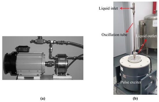
Figure 4.
Flow pulsation generator: (a) hydro-mechanical pulsator; (b) inertial flow pulsator.
The principle of the inertial flow pulsator is that the oscillation in liquid flow is excited by the excitation of mechanical vibrations of a part of the pressurized manifold (i.e., oscillation tube). The pulsation is generated by the rapid displacement of a rigid section of tubing through which the liquid flows. The liquid will generate pressure pulsations determined by the periodic displacement of its mass instead of moving parts. Thus, the sealing performance is good, even if the inlet pressure in the manifold is high. First, the sinusoidal signals of different frequencies generated by the signal generator are amplified by a power amplifier. Then, the amplified signal is transmitted to the pulse exciter. Finally, the oscillation tube of the pulse exciter will make a periodic reciprocating motion corresponding to the frequency of the given signal, driving the liquid in the oscillation tube to flow periodically. In this way, a pulsating flow at a specific frequency can be output into the liquid feedline.
To improve the pulsating performance, Bazarov [31] argued that the velocity of liquid in the oscillation tube should not be greater than 12 m/s and the length of this tube should be less than 1/10 of the length of the pressure wave of the excited frequency in the liquid. Therefore, the size of the oscillation tube can be designed according to the flow rate and the pulsation frequency required for the experiment, as shown in Figure 4b.
2.3.2. Electric Conductance Method
The flow pulsation of liquid at injector outlet manifests as the change of annular liquid film thickness, whereas the liquid film thickness can be measured via the electric conductivity of liquid between two electrodes in injector chamber. Therefore, the purpose is to calibrate the relation between the voltage of two electrodes and the liquid film thickness. The measurement principle of the electric conductance method (ECM) is elaborated by taking an example of an LS injector with a simple structure. The schematic and structure parameters of LS injector are shown in Figure 5 and Table 3, respectively. Two ring electrodes composed of porous titanium are placed near the outlet of LS injector. The conductivity between the two electrodes varies with the liquid film thickness. The expression of the resistance of annular liquid column is
where is the resistivity of conductive liquid, is the length of annular liquid column, and is the cross-sectional area of annular liquid column, which is expressed as
where is the inner radius of injector outlet, and is the liquid film thickness. Substituting Equation (2) into Equation (1), the theoretical expression between the annular liquid film thickness and the resistance of annular liquid column can be obtained:

Figure 5.
Principle of ECM: (a) schematic of ECM; (b) schematic of LS injector.

Table 3.
Geometrical parameters of the LS injector.
Cylindrical ceramic rods of different diameters were placed in the swirl chamber to calibrate the measuring system of liquid film thickness. When the liquid flowed through the swirl chamber, liquid films of different thicknesses were generated in the annular space between the inner wall of injector and the ceramic rods of different diameters. By recording the corresponding voltage signal value, the calibration curve of liquid film thickness and voltage could be obtained as drawn in Figure 6. The same measurement principle of liquid film thickness and the installation method of electrodes were also adopted for the experiment of the dynamic characteristics of GCSC injectors.
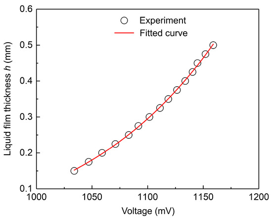
Figure 6.
Calibration curve of the LS injector: voltage vs. film thickness.
The small fluctuations of liquid film thickness in injector and the considerable noise associated with the flow process make it difficult to measure the conductivity of the liquid column between the electrodes. In order to solve this problem, a homemade liquid film thickness sensor based on a lock-in amplifier circuit was used, which can meet the requirements of liquid film thickness acquisition at frequency up to 500 Hz. The raw data of the measured liquid film thickness are shown in Figure 7.
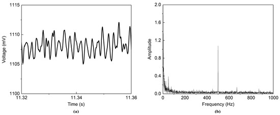
Figure 7.
Raw data of LS injector when , , and : (a) raw data of liquid film thickness; (b) fast Fourier transform (FFT).
There are several sources of uncertainty in the electric conductance method to measure liquid film thickness [13]. First, the machining of the calibration ceramic rods caused uncertainty. A series of rods with different diameters correspond to different liquid film thicknesses. The rods were fabricated with a tolerance of 0.001 mm, and it is assumed that the machining error complied with the even distribution. The second source of uncertainty was the change of environmental conditions, such as the variation of the specific conductivity of the liquid. To reduce this uncertainty, the test medium for calibrations and experiments adopted a sodium chloride solution (1 g sodium chloride per 10 L distilled water). Third, less important sources of uncertainty include the limitations of this measuring system, which produces an average conductivity signal. This method measures the average liquid film thickness between the two electrodes, whereas the liquid film thickness varies axially. However, this error was omitted because the distance between the electrodes was much smaller than the wavelength of the liquid film surface [30]. Moreover, type A standard uncertainty caused by measurement repeatability is another source of uncertainty. In steady condition, the measurement was repeated several times. The standard deviation of the measured film thickness was calculated using the Bessel formula. The maximum standard deviation is denoted as the type A standard uncertainty. Table 4 summarizes the above sources of uncertainty. The combined standard uncertainty = 0.017 mm.

Table 4.
Assessment of uncertainty of measured liquid film thickness.
3. Results and Discussion
3.1. The Pulsation Test of Inertial Flow Pulsator and the Validation of Operating Conditions
A series of tests were conducted on the excitation system of pulsating flow under backpressure conditions to determine the feasibility of the inertial flow pulsator that was manufactured in this study. The LS injector was mounted in the backpressure chamber. The outflow exit of the liquid in the inertial flow pulsator was connected to the injector using a metal hose. The pressure signal in the liquid cavity of the injector is collected as the output signal for the test. As shown in Figure 8, the inertial flow pulsator can generate sinusoidal pressure signals with sufficiently large amplitudes under a backpressure environment, where the amplitude varies by more than 15%. Moreover, the spectrum analysis (Figure 8b) shows that the pulsation frequency of the output pressure signal is consistent with the one excited by the upstream signal generator (100 Hz). For the dynamic characteristics experiment under high backpressure, the inlet pressure in the manifold increases with the increase in the chamber backpressure when the pressure drop in the manifold remains constant. Comparing the pressure pulsation curves obtained under different operating conditions (Figure 8c), it is found that a larger input pressure leads to a larger amplitude of oscillation. Therefore, the inertial flow pulsator is a viable solution to excite flow pulsations for the injectors in dynamic spray experiments under high backpressure.
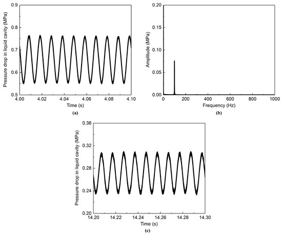
Figure 8.
Pressure signal of LS injector when = 1 MPa and = 100 Hz: (a) = 0.65 MPa; (b) FFT; (c) = 0.3 MPa.
In the experiments that simulate the spray process of real rocket engines, it is difficult to produce high-frequency pulsations in supply pressure [30]. This is because the increase in frequency makes it difficult for the flow pulsation generator to generate pressure pulsation of incoming flow at high backpressure. The inertial flow pulsator is based on mechanical vibrations causing the pulsation of the pipeline flow. Considering the influence of mechanical vibration on the stable operation of the whole experimental system, the inlet and outlet of the inertial flow pulsator are connected with the main feedline by means of a metal hose. In this way, the vertical displacement of the oscillation tube can be matched to buffer the influence of the system pipeline oscillation on the pulsation signal of the liquid pressure in the tube. Using this inertial flow pulsator, high-frequency pressure pulsations can be generated in a high backpressure environment. The pressure pulsation at 500 Hz from the pulse exciter, after passing through the feedline, causes a pressure signal in the liquid cavity of LS injector as shown in Figure 9. It can be seen that this inertia flow pulsator can still cause a regular pulsation of the incoming flow at a higher frequency.
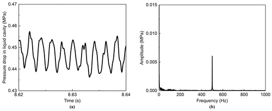
Figure 9.
Pressure signal of LS injector when = 1.5 MPa, = 0.45 MPa, and = 500 Hz: (a) pressure curve; (b) FFT.
The liquid injector of the GCSC injector used in the experiments is an open-ended swirl structure. It is more difficult for the open-ended swirl injector to cause the oscillation of the liquid film at the injector outlet because there is no converging section downstream of the swirl chamber [32]. In order to find the proper conditions that are easy to start oscillating, it is necessary to validate the operating conditions for the GCSC injector. In the case of the same power output of the power amplifier and the unchanged working conditions, the experiments were conducted in different supply orders of liquid and gas phases. The test results show that the different supply order of the liquid and gas flow caused the amplitudes of pressure drop in the liquid cavity of the GCSC injector to be different, as shown in Figure 10.
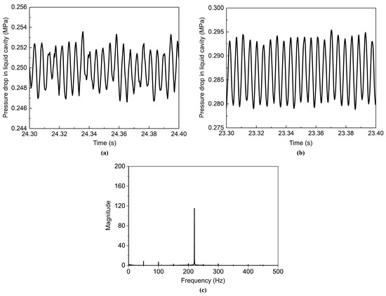
Figure 10.
Pressure pulsation curve of liquid cavity of GCSC injector and the FFT graph: (a) supply gas first; (b) supply liquid first; (c) FFT.
The ambient pressure of the backpressure chamber is atmospheric pressure. The output pulsation frequency of the signal generator (i.e., the pressure pulsation frequency of the inertial flow pulsator) is 200 Hz. The pressure drop in the liquid feedline is 0.25 MPa (corresponding to the liquid flow rate of 23 g/s). The gas flow rate is regulated to 15 L/min by the gas flow controller. As seen in Figure 10, the amplitude of the dimensionless pulsation of the pressure drop in the liquid cavity caused by supplying liquid flow first is larger than that caused by supplying gas flow first. Moreover, the variation of pressure pulsation of the former is more regular. The possible reason for this is that supplying the gas phase first will cause the nitrogen gas flow to occupy the exit of the liquid channel at the recess section of the injector. Then, opening the liquid feedline, the gas will have a strong shear effect on the liquid film, causing the liquid film on the nozzle wall to pulsate non-harmonically. The pulsation of the liquid film thickness is transmitted to the liquid cavity, resulting in an unsmooth pressure curve.
3.2. Steady State
The steady-state experiments were first conducted using the No. 2 GCSC injector. In this work, the steady-state characteristics of the injector atomization were obtained firstly. Then, the inertial flow pulsator was turned on for the experimental study of dynamic characteristics. In these experiments, the pressure drop in the liquid feedline including the injector was 0.25 MPa (corresponding to the liquid flow rate of 23 g/s). The gas flow rate was controlled to 15 L/min by the gas flow controller. The experiments were conducted under the operating conditions of 0.3 MPa, 0.6 MPa, and 0.9 MPa for the chamber backpressures, respectively.
To capture the details of the spray field, the spray field was photographed using a high-speed camera with a sampling frequency of 20,000 frames per second. The resulting instantaneous spray patterns under different chamber backpressures Pb are shown in Figure 11. Several possible criteria for the breakup length are defined in the literature. In this study, the spray breakup length was defined as the vertical distance from the injector exit to the first point where the liquid sheet started to break up into liquid filaments. The breakup length was obtained using 20 images from the backlighting photography. Additionally, the error bars were obtained from the measurement uncertainty of 20 samples, which were analyzed by solving the sample standard deviation. Figure 12 shows the effect of chamber backpressure on the spray breakup length L.

Figure 11.
Spray patterns of the GCSC injectors under different chamber backpressures: (a) = 0.3 MPa; (b) = 0.6 MPa; (c) = 0.9 MPa.
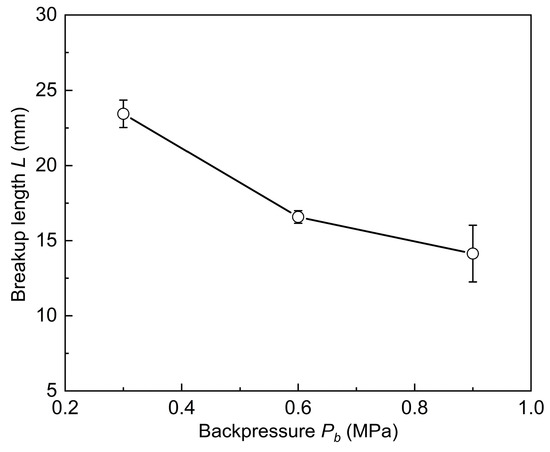
Figure 12.
Effect of the chamber backpressure Pb on the breakup length L.
The steady-state spray images under different chamber backpressure conditions (Figure 11) show that the surface of the liquid sheet becomes folded from smooth with increasing ambient pressure. The development of dense instable waves prompts the liquid sheet to rupture earlier. This is demonstrated by the fact that the spray breakup length L becomes shorter with increasing the chamber backpressure Pb (Figure 12). The increase in backpressure Pb essentially leads to an increase in the density of the ambient gas, which strengthens the aerodynamic force of the gas on the annular liquid sheet downstream of the injector outlet [22,33]. Therefore, the larger chamber backpressure drives the liquid sheet surface to be more unstable and wrinkled, making the breakup length L of the liquid sheet in the spray field shorter.
Furthermore, the mechanism by which the backpressure Pb shortens the breakup length L by increasing the ambient gas density can be analyzed from the linear instability theory. For an annular swirling liquid sheet, Kim [33] considered the attenuation of the sheet and corrected the normalized breakup length relation according to the injection conditions and the ambient gas based on the work of Dombrowski [34] and Hagerty [35], as shown in the following:
where is the orifice radius; is the initial liquid sheet thickness at the injector exit; is the half of the spray angle; and are the gas and the liquid density, respectively; is a constant; is the liquid Weber number, which is given by
where is the axial velocity of the liquid sheet; is the liquid sheet thickness at the injector exit; is the surface tension. In these experiments, the operating conditions (such as pressure drop and the gas flow rate) were fixed except for the chamber backpressure so that the was constant. However, the increased ambient pressure will result in an increment in the ambient gas density . As stated by Kim [33], the spray angle before breakup is independent of the ambient gas density and is only a function of . Therefore, in Equation (4), it is concluded that when the gas density increases, the breakup length L will decrease. The above result of theoretical analysis is consistent with the trend of the effect of the backpressure Pb on the breakup length L observed in Figure 12.
Comparison with the previous study [22,33] revealed that the effect of backpressure on the spray cone angle was less pronounced in these experiments in the backpressure chamber. In contrast, the previous study showed that the increase in the backpressure leads to a decrease in the spray cone angle. The possible reasons for this phenomenon in the present experiments are explained as follows. The spraying environment of the backpressure chamber is a confined space. The slight increase in ambient pressure in the chamber during the spraying process hinders the continuous supply of the gas flow in the upstream feedline. Although the increase in the backpressure will make the spray cone angle smaller, the reduction of gas flow in the GCSC injector makes the spray angle larger. Eventually, the chamber backpressure has less effect on the spray cone angle.
3.3. The Effect of the Chamber Backpressure
After acquiring the steady-state spray data of the GCSC injector, the dynamic characteristics of the spraying are investigated by turning on the inertial flow pulsator. The raw data (i.e., voltage) of the liquid film pulsation are measured using the liquid film thickness sensor. The liquid film thickness at the GCSC injector outlet is calibrated using a method similar to that in Section 2.3.2. As shown in Figure 13, the raw voltage signal of liquid film is converted into the liquid film thickness value. Accordingly, it is possible to convert a series of raw voltage signals measured by a liquid film thickness sensor into a dynamic value of liquid film thickness over time, as shown in Figure 14. Based on the processing results of the Fourier transform (Figure 14c), it is found that the main frequency of the pulsating signal of liquid film thickness was 220 Hz, which is consistent with the pulsation frequency outputted by the signal generator.
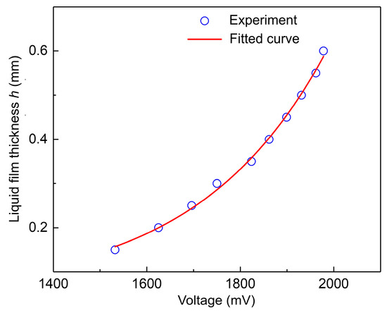
Figure 13.
Calibration curve of the GCSC injector: voltage vs. film thickness.
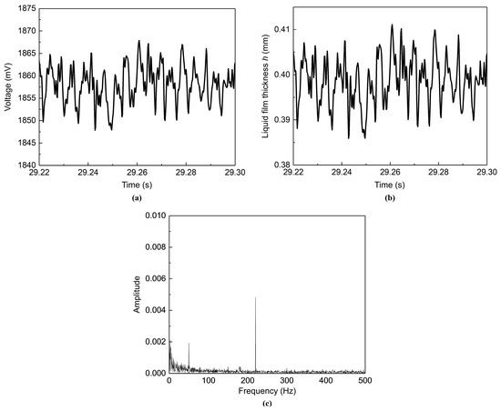
Figure 14.
Pulsation curve of liquid film thickness and the FFT graph when = 220 Hz: (a) raw data of liquid film thickness; (b) liquid film thickness; (c) FFT.
The pressure pulsation signal in the liquid cavity of the injector is measured using a dynamic pressure transducer in the liquid injector. According to the calibration curve of the liquid film thickness of the GCSC injector, the pulsation curve of the liquid film thickness is then plotted against the pressure signal in Figure 15 for comparison. It can be seen that the pressure in the liquid cavity varies steadily and regularly in the form of a sinusoidal signal. This pressure perturbation in the swirl chamber causes the instability of the liquid film, which in turn causes the liquid film thickness to pulsate. The liquid film thickness evolves temporally with irregular periodic variations accompanied by the pressure pulsations.
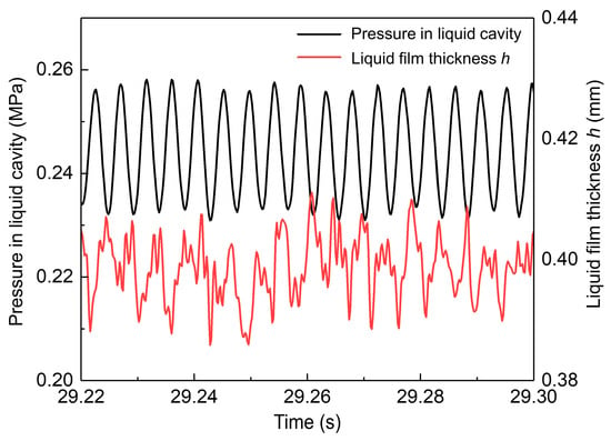
Figure 15.
Pulsation curves of the pressure in liquid cavity and the liquid film thickness when = 220 Hz.
The dynamic theory of injector addresses the accurate prediction of the dynamics characteristics of a swirl injector when the inflow pressure fluctuates, which was developed by Bazarov [36]. By using the inviscid fluid mechanics equation that controls the internal flow of the injector, the frequency characteristic equation of an injector is derived by an analytical method. The dynamic behavior of an injector is characterized by the response function given by
According to this theory, the pulsations of flow rate or pressure drop bring about the development of surface waves on the gas–liquid interface as well as vortex waves of different circumferential velocities within the swirling liquid itself.
It can be seen from Equation (6) that a vital objective of the experiments on the dynamic characteristics of an injector is to obtain the pulsating flow of the injector. Axial velocity fluctuations and liquid film thickness fluctuations are in the same phase. Therefore, according to the dynamic theory of injector, the instantaneous volume flow rate of the swirl injector can be obtained by multiplying the axial velocity of the flow and the flow area in the swirl chamber, as presented in the following equation:
where is the radius of gas vortex, which can be found by the difference between the nozzle radius and the liquid film thickness; is the nozzle radius of the swirl injector; is the amplitude of liquid film thickness, which is obtained by subtracting its average thickness from the liquid film thickness curve in Figure 15; is the steady-state axial velocity of the flow, which is calculated from the steady-state flow rate by the following equation:
Using Equations (7) and (8), the liquid film thickness is converted into the flow rate at the injector outlet, and the pulsation of the flow rate at the injector outlet can be further obtained. According to the definition of the injector dynamic characteristics (Equation (5)), the influence of various backpressure conditions on the dynamic characteristics of GCSC injectors with different recess structures can be summarized as shown in Figure 16. The variation range of pulsation frequency is 180–270 Hz. It can be seen from the amplitude–frequency characteristic curve of each GCSC injector that when the chamber backpressure Pb is constant, the amplitude characteristic of the injector will show a downward trend as the pulsation frequency increases. This indicates that the increase in the pulsation frequency of the pressure in the swirl chamber of the injector can suppress the pulsation amplitude of the liquid film to a certain extent.
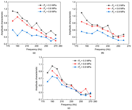
Figure 16.
Effect of the chamber backpressure Pb on the dynamic characteristics of different GCSC injectors: (a) No.1 injector ( = 13 mm); (b) No.2 injector ( = 8 mm); (c) No. 3 injector ( = 3 mm).
It can be further seen from Figure 16 that for each GCSC injector, the dimensionless amplitude of the flow rate at the injector outlet tends to decrease as the chamber backpressure Pb increases. That is, the increase in chamber backpressure Pb has a suppressive effect on the pulsation of the outlet flow of the injector; in particular, when the recess length of the injector is larger, this phenomenon is more obvious. This is because the density of the ambient gas in the chamber increases when the chamber backpressure Pb increases. Then, the liquid sheet ejected from the injector will consume more momentum when it moves the surrounding quiescent gas. Therefore, the momentum transferred from the moving liquid sheet to the quiescent ambient gas is greater, resulting in a reduction in the pulsation amplitude of the flow rate at the injector outlet and a decrease in the transfer function. This is similar to the influence of the chamber backpressure on the dynamic characteristics of an LS injector of the single-component fluid [33].
3.4. The Effect of the Recess Length
In order to study the effect of the recess length of the GCSC injector on the dynamic characteristics under chamber backpressure, the recess lengths of the No.1, No.2, and No.3 injectors used in the experiments were designed to be 13 mm, 8 mm, and 3 mm, respectively. Nitrogen gas was charged into the backpressure chamber to make the ambient backpressure Pb remain 0.6 MPa. The pressure drop in the liquid feedline was 0.25 MPa. The gas flow rate in the gas feedline was 15 L/min. The pulsation frequency range of the signal generator was 180–270 Hz.
The instantaneous spray patterns of the GCSC injectors with different recess lengths are shown in Figure 17. The trend of the effect of the recess length on the breakup length L of the liquid sheet is obtained by processing the spray images, as shown in Figure 18. The injector with a shorter recess length has a liquid sheet that ruptures earlier. That is, a decrease in the recess length leads to a decrease in the spray breakup length L. The possible reason for this is that the reduction in recess length reduces the distance between the gas injector outlet and the liquid injector outlet. The wall of the shorter recess section has little inhibiting effect on the perturbation of the annular liquid film, compared with the longer recess section. Additionally, the gas flow at the center significantly shears the liquid sheet. As a result, the break-up process of the centrifugal liquid sheet at the injector exit is more intense. Ultimately, it is manifested as a reduction in the spray breakup length L.

Figure 17.
Spray patterns of the GCSC injectors with different recess lengths: (a) = 3 mm; (b) = 8 mm; (c) = 13 mm.
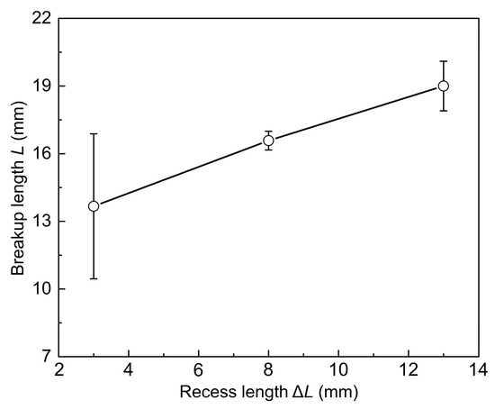
Figure 18.
Effect of the recess length on the breakup length L.
In addition, the influence mechanism of the recess length on the breakup length of the liquid sheet of injection in backpressure can be analyzed by the linear instability theory. For a swirl coaxial injector, the quantitative relationship between the recess length and the disturbance amplitude of the liquid sheet can be expressed as follows [23]:
where is the disturbance amplitude of the liquid sheet at the injector exit; is the initial disturbance amplitude inside the recess section; is the disturbance wave number; is the recess length of the swirl coaxial injector. In these experiments about the effect of the recess length, the operating conditions, such as the pressure drop, the gas flow rate, and the chamber backpressure, were fixed. Additionally, the initial disturbance amplitude of the liquid sheet inside the recess section was constant. However, the disturbance amplitude of the liquid sheet at the injector exit would be different with the changed recess length . From Equation (9), the disturbance amplitude of the liquid sheet decreases as the recess length increases. This decreased disturbance amplitude increases the breakup length L of the liquid sheet according to the theory of Clark and Dombrowski [37], as shown in the following equation:
where is the sheet thickness parameter; is the axial sheet velocity. From the above, it is theoretically explained that an injector with a larger recess length produces a longer breakup length (Figure 18), forming a more stable conical liquid sheet.
Using the similar approach in Section 3.3, the effect of the recess length of the GCSC injectors on the dynamic characteristics of spraying can be obtained under different chamber backpressure conditions. Figure 19 shows the effect of various recess lengths on the dynamic characteristics of the GCSC injectors in the pulsation frequency ranges of 180–270 Hz. It can be seen from the figures that for lower backpressure conditions, as the recess length increases, the amplitude–frequency characteristics of the injector generally increase. This is because when the recess section of the GCSC injector becomes longer, the gas from the outlet of the gas injector will enhance the impact effect in the recess section, to tear the liquid film inside the injector tempestuously. This leads to an increase in the oscillation of the liquid flow at the injector outlet, which in turn increases the amplitude–frequency characteristics of the spraying for the injector.
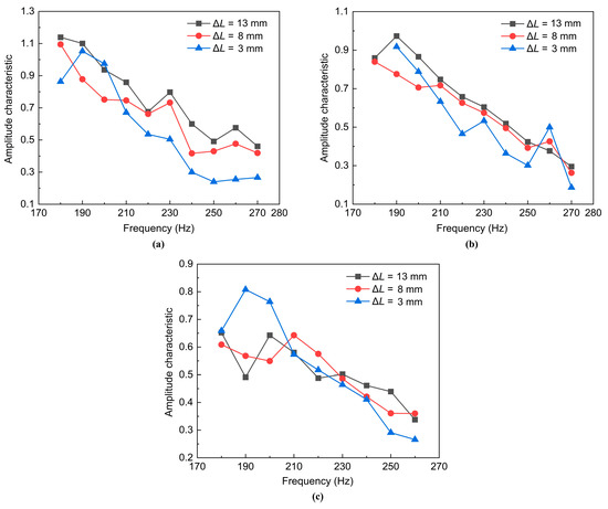
Figure 19.
Effect of the recess length on the dynamic characteristics of GCSC injector under different chamber backpressures: (a) Pb = 0.3 MPa; (b) Pb = 0.6 MPa; (c) Pb = 0.9 MPa.
However, it is not difficult to see that the above influence law is not obvious in the lower range of the pulsation frequency of the incoming flow (about 220 Hz or less). In particular, when the chamber backpressure Pb is 0.9 MPa, the influence of the recess length of the injector on the amplitude–frequency characteristics of the outlet flow rate is not obvious, as shown in Figure 19c. The possible reason is that as the pulsation frequency of the pressure decreases, the oscillation amplitude of the liquid film inside the injector becomes relatively large. Additionally, the GCSC injector is a gas–liquid coaxial structure with a gas center. When the outlet width of the injector is constant, the scouring effect of the gas flow on the liquid film will be strengthened, resulting in irregular disturbance for the larger pulsation of the liquid film. Therefore, the influence of the recess length on the dynamic characteristics of the GCSC injector was driven not to be obvious at low pulsation frequencies.
4. Conclusions
Experimental observations of the dynamic characteristics generated by the GCSC injectors under various ambient pressures have been presented and analyzed. In order to simulate the high backpressure ambient in the combustion chamber of a rocket engine, an experimental system of the dynamic injection in a backpressure chamber is constructed. An inertial flow pulsator is designed and manufactured to generate the dynamic pulsation of the flows that feed to the injector. The electric conductance method is adopted to measure steady and instantaneous liquid film thickness. The steady state of the spraying under backpressure is shown in detail. Emphatically, the effects of the chamber backpressure and the recess length of the injectors on the dynamics characteristics of the spray are investigated. The conclusions are drawn as follows:
(1) The issue of liquid leakage is solved by the inertial flow pulsator, which can generate sinusoidal pressure signals with sufficient amplitudes that vary by more than 15% under backpressure. A larger input pressure leads to a larger amplitude of pulsation. This pulsator meets the pressure pulsation with a frequency of 500 Hz. A sodium chloride solution is used to calibrate the liquid film thickness to improve the accuracy of the electric conductance method. The measurement error of this method is 0.017 mm, satisfying the experimental accuracy of liquid film thickness.
(2) The increase in chamber backpressure leads to an increase in the gas density, which strengthens the aerodynamic force of the gas on the liquid sheet. Then, the surface of the liquid sheet becomes more folded, prompting the liquid sheet to rupture earlier with a shorter breakup length. An increase in backpressure increases the momentum transfer of the gas–liquid flow, resulting in a reduction in the pulsation amplitude of the liquid film. Therefore, chamber backpressure suppresses the pulsation of the flow at the injector outlet, especially for a longer recess length.
(3) A decrease in the recess length leads to a reduction in the breakup length because of the enhanced shearing effect in a narrower recess section. As the recess length increases, the amplitude characteristics of outlet flow generally increase, especially for a lower backpressure. Moreover, when the recess length and the chamber backpressure are constant, the increase in the pulsation frequency of the pressure can suppress the pulsation amplitude of the outlet flow under backpressure.
Author Contributions
Conceptualization, X.Z. and W.Q.; methodology, Q.G.; investigation, Q.G. and D.Z.; writing—original draft preparation, W.Q.; writing—review and editing, W.Q. and Q.F.; supervision, L.Y.; funding acquisition, L.Y. and Q.F. All authors have read and agreed to the published version of the manuscript.
Funding
This work was supported by the National Natural Science Foundation of China (Grant Nos. 12272026, 11922201 and U1837211).
Data Availability Statement
Not applicable.
Acknowledgments
The authors thank the reviewers for their great help during the review progress.
Conflicts of Interest
The authors declare no conflict of interest.
References
- Kang, Z.; Wang, Z.; Li, Q.; Cheng, P. Review on pressure swirl injector in liquid rocket engine. Acta Astronaut. 2018, 145, 174–198. [Google Scholar]
- Im, J.H.; Cho, S.; Yoon, Y.; Moon, I. Comparative study of spray characteristics of gas-centered and liquid-centered swirl coaxial injectors. J. Propul. Power 2010, 26, 1196–1204. [Google Scholar] [CrossRef]
- Inoue, C.; Watanabe, T.; Himeno, T.; Uzawa, S. Liquid Jet Dynamics and Primary Breakup Characteristics at Near-Field of Coaxial Type Injector. In Proceedings of the 46th AIAA/ASME/SAE/ASEE Joint Propulsion Conference & Exhibit, Nashville, TN, USA, 25–28 July 2010. [Google Scholar]
- Cohn, R.; Strakey, P.; Bates, R.; Talley, D.; Muss, J.; Johnson, C. Swirl Coaxial Injector Development. In Proceedings of the 41st Aerospace Sciences Meeting and Exhibit, Reno, NV, USA, 6–9 January 2003. [Google Scholar]
- Bazarov, V. Influence of Propellant Injector Stationary and Dynamic Parameters on High Frequency Combustion Stability. In Proceedings of the 32nd Joint Propulsion Conference and Exhibit, Lake Buena Vista, FL, USA, 1–3 July 1996. [Google Scholar]
- Harrje, D.T.; Reardon, F.H. Liquid Propellant Rocket Combustion Instability; Scientific and Technical Information Office, National Aeronautics and Space Administration, U.S. Government Printing Office: Washington, DC, USA, 1972; Volume 1. [Google Scholar]
- Ismailov, M.; Heister, S.D. Dynamic response of rocket swirl injectors, part II: Nonlinear dynamic response. J. Propul. Power 2011, 27, 412–421. [Google Scholar] [CrossRef]
- Li, P.; Yang, L.; Fu, Q.; Fang, Z. Spray characteristics of the nanoparticle-containing gel propellants by using an improved single-phase nozzle. Fuel 2022, 315, 122968. [Google Scholar] [CrossRef]
- Ismailov, M.M. Modeling of Classical Swirl Injector Dynamics. Ph.D. Thesis, Purdue University, West Lafayette, IN, USA, 2010. [Google Scholar]
- Liu, L.; Zhang, S.; Fu, Q. Spray characteristics of gel fuel in a gas-centered coaxial swirl injector with variable recess ratios. Fuel 2022, 319, 123766. [Google Scholar] [CrossRef]
- Bazarov, V.G.; Yang, V. Liquid-propellant rocket engine injector dynamics. J. Propul. Power 1998, 14, 797–806. [Google Scholar] [CrossRef]
- Fu, Q.F.; Yang, L.J.; Wang, X.D. Theoretical and experimental study of the dynamics of a liquid swirl injector. J. Propul. Power 2010, 26, 94–101. [Google Scholar] [CrossRef]
- Fu, Q.F.; Yang, L.; Qu, Y.Y.; Gu, B. Geometrical effects on the fluid dynamics of an open-end swirl injector. J. Propul. Power 2011, 275, 929–936. [Google Scholar] [CrossRef]
- Bazarov, V. Non-Linear Interactions in Liquid-Propellant Rocket Engine Injectors. In Proceedings of the 34th AIAA/ASME/SAE/ASEE Joint Propulsion Conference and Exhibit, Cleveland, OH, USA, 13–15 July 1998. [Google Scholar]
- Bazarov, V. Self-Pulsations in Coaxial Injectors with Central Swirl Liquid Stage. In Proceedings of the 31st Joint Propulsion Conference and Exhibit, San Diego, CA, USA, 10–12 July 1995. [Google Scholar]
- Yang, V.; Puri, P. Design and Dynamics of Jet and Swirl Injectors. In Liquid Rocket Thrust Chambers; Astronautics and Aeronautics Inc.: Reston, VA, USA, 2004; pp. 19–103. [Google Scholar]
- Park, G.; Oh, S.; Yoon, Y.; Choi, J.Y. Characteristics of gas-centered swirl-coaxial Injector with liquid flow excitation. J. Propul. Power 2019, 35, 624–631. [Google Scholar] [CrossRef]
- Park, G.; Lee, J.; Oh, S.; Yoon, Y.; Sohn, C.H. Characteristics of gas-centered swirl coaxial injector with acoustic excitation of gas flow. AIAA J. 2017, 55, 894–901. [Google Scholar] [CrossRef]
- Sahoo, S.K.; Gadgil, H. Dynamics of self-pulsation in gas-centered swirl coaxial injector: An experimental study. J. Propul. Power 2021, 373, 450–462. [Google Scholar]
- Oh, S.; Park, G.; Kim, S.; Lee, H.; Yoon, Y.; Choi, J.Y. A Study on dynamic characteristics of gas centered swirl coaxial injector varying tangential inlet diameter with liquid pulsation. J. ILASS-Korea 2017, 22, 62–68. [Google Scholar]
- Bai, X.; Cheng, P.; Sheng, L.; Li, Q.; Zhang, X.; Kang, Z. Effects of backpressure on self-pulsation characteristics of liquid-centered swirl coaxial injectors. Int. J. Multiphas. Flow 2019, 116, 239–249. [Google Scholar]
- He, X.; Chen, C.; Yang, Y.; Yan, Z. Experimental study on the flow field distribution characteristics of an open-end swirl injector under ambient pressure. Aerosp. Sci. Technol. 2020, 98, 105691. [Google Scholar]
- Kim, D.; Jeong, W.; Im, J.; Yoon, Y. The Characteristics of Swirl Coaxial Injector under Varying Geometric and Environmental Conditions. In Proceedings of the 40th AIAA/ASME/SAE/ASEE Joint Propulsion Conference and Exhibit, Fort Lauderdale, FL, USA, 11–14 July 2004. [Google Scholar]
- Zhang, Z.; Liu, Y.; Hu, H. Effects of chamber pressure on the kinematic characteristics of spray flows exhausted from an airblast atomizer. Exp. Therm. Fluid Sci. 2022, 130, 110514. [Google Scholar]
- Zhang, L.; Wang, X.; Li, Y.; Yeh, S.T.; Yang, V. Supercritical fluid flow dynamics and mixing in gas-centered liquid-swirl coaxial injectors. Phys. Fluids 2018, 30, 075106. [Google Scholar] [CrossRef]
- Mayer, W.; Tamura, H. Propellant injection in a liquid oxygen/gaseous hydrogen rocket engine. J. Propul. Power 1996, 12, 1137–1147. [Google Scholar] [CrossRef]
- Kenny, R.J.; Hulka, J.R.; Moser, M.D.; Rhys, N.O. Effect of chamber backpressure on swirl injector fluid mechanics. J. Propul. Power 2009, 25, 902–913. [Google Scholar]
- Cho, S.; Park, G.; Chung, Y.; Yoon, Y.; Bazarov, V.G. Surface instability on cryogenic swirl flow at sub-to supercritical conditions. J. Propul. Power 2014, 30, 1038–1046. [Google Scholar] [CrossRef]
- Chen, C.; He, X.; Liu, C.; Yang, Y.; Tang, Z. Experimental study on the flow field distribution characteristics of a gas–liquid swirl coaxial injector under ambient pressure. Aerosp. Sci. Technol. 2021, 114, 106757. [Google Scholar]
- Fu, Q.F.; Yang, L.J.; Qu, Y.Y. Measurement of annular liquid film thickness in an open-end swirl injector. Aerosp. Sci. Technol. 2011, 15, 117–124. [Google Scholar] [CrossRef]
- Bazarov, V.; Lee, E.; Lineberry, D.; Swanner, B.; Frederick, R. Pulsator Designs for Liquid Rocket Injector Research. In Proceedings of the 43rd AIAA/ASME/SAE/ASEE Joint Propulsion Conference & Exhibit, Cincinnati, OH, USA, 8–11 July 2007. [Google Scholar]
- Chung, Y.; Kim, H.; Jeong, S.; Yoon, Y. Dynamic characteristics of open-type swirl injector with varying geometry. J. Propul. Power 2016, 32, 583–591. [Google Scholar] [CrossRef]
- Kim, D.; Im, J.H.; Koh, H.; Yoon, Y. Effect of ambient gas density on spray characteristics of swirling liquid sheets. J. Propul. Power 2007, 23, 603–611. [Google Scholar] [CrossRef]
- Dombrowski, N.; Hooper, P.C. The effect of ambient density on drop formation in sprays. Chem. Eng. Sci. 1962, 17, 291–305. [Google Scholar] [CrossRef]
- Hagerty, W.W.; Shea, J.F. A study of the stability of plane fluid sheets. J. Appl. Fluid Mech. 1955, 22, 509–514. [Google Scholar] [CrossRef]
- Bazarov, V. Dynamics of Liquid Injectors; Mashinostroenie: Moscow, Russia, 1979; p. 35. [Google Scholar]
- Clark, C.J.; Dombrowski, N. Aerodynamic instability and disintegration of inviscid liquid sheets. Proc. R. Soc. Lond. A. Math. Phys. Sci. 1972, 329, 467–478. [Google Scholar]
Disclaimer/Publisher’s Note: The statements, opinions and data contained in all publications are solely those of the individual author(s) and contributor(s) and not of MDPI and/or the editor(s). MDPI and/or the editor(s) disclaim responsibility for any injury to people or property resulting from any ideas, methods, instructions or products referred to in the content. |
© 2023 by the authors. Licensee MDPI, Basel, Switzerland. This article is an open access article distributed under the terms and conditions of the Creative Commons Attribution (CC BY) license (https://creativecommons.org/licenses/by/4.0/).