Article

Thoughts on the Importance of Similitude and Multi-Axial Loads When Assessing the Durability and Damage Tolerance of Adhesively-Bonded Doublers and Repairs

1
Centre of Expertise for Structural Mechanics, Department of Mechanical and Aerospace Engineering, Monash University, Clayton, VIC 3800, Australia
2
ARC Industrial Transformation Training Centre on Surface Engineering for Advanced Materials, Faculty of Science, Engineering and Technology, Swinburne University of Technology, John Street, Hawthorn, VIC 3122, Australia
3
Zentech International Limited, 590B Finchley Road, London NW11 7RX, UK
4
Department of Mechanical Engineering, Imperial College London, Exhibition Road, London SW7 2AZ, UK
*
Author to whom correspondence should be addressed.
Aerospace 2023, 10(11), 946; https://doi.org/10.3390/aerospace10110946
Submission received: 24 August 2023 / Revised: 4 November 2023 / Accepted: 4 November 2023 / Published: 7 November 2023
(This article belongs to the Special Issue Structural Airworthiness and Life Extension of Aging Aircraft)

Abstract

:
Adhesively bonded doublers and adhesively bonded repairs are extensively used to extend the operational life of metallic aircraft structures. Consequently, this paper focuses on the tools needed to address sustainment issues associated with both adhesively bonded doublers and adhesively bonded repairs to (metallic) aircraft structures, in a fashion that is consistent with the building-block approach mandated in the United States Air Force (USAF) airworthiness certification standard MIL-STD-1530D and also in the United States (US) Joint Services Structural Guidelines JSSG-2006. In this context, it is shown that the effect of biaxial loads on cohesive crack growth in a bonded doubler under both constant amplitude fatigue loads and operational flight loads can be significant. It is also suggested that as a result, for uniaxial tests to replicate the cohesive crack growth seen in adhesively bonded doublers and adhesively bonded repairs under operational flight loads, the magnitude of the applied load spectrum may need to be continuously modified so as to ensure that the crack tip similitude parameter in the laboratory tests reflects that seen in the full-scale aircraft.

1. Introduction

The United States Air Force (USAF) airworthiness certification standard MIL-STD-1530D [1] explains that durability and damage tolerance (DADT) analysis plays a central role in the airworthiness certification of a military aircraft and that the role of testing is to validate/correct the analysis. MIL-STD-1530D also explains that the DADT analysis should be based on linear-elastic fracture-mechanics (LEFM) [2,3,4]. Furthermore, both the United States (US) Joint Services Structural Guidelines JSSG-2006 [5] and MIL-STD-1530D [1] explain that the analysis should be based on a building-block approach, which involves tests and analyses on coupons, elements, sub-components and full-scale structures, see Figure 1. The USAF Damage Tolerance Design Handbook [6] notes that similitude is essential to the design/airworthiness assessment of military aircraft. Furthermore, as discussed in [7], it is important that the safety of bonded airframes be ensured in some way with respect to the possibility of sudden failure of the bonded joint due to long-term operation of the bond-line and/or the effect of hail or impact damage to the bond.
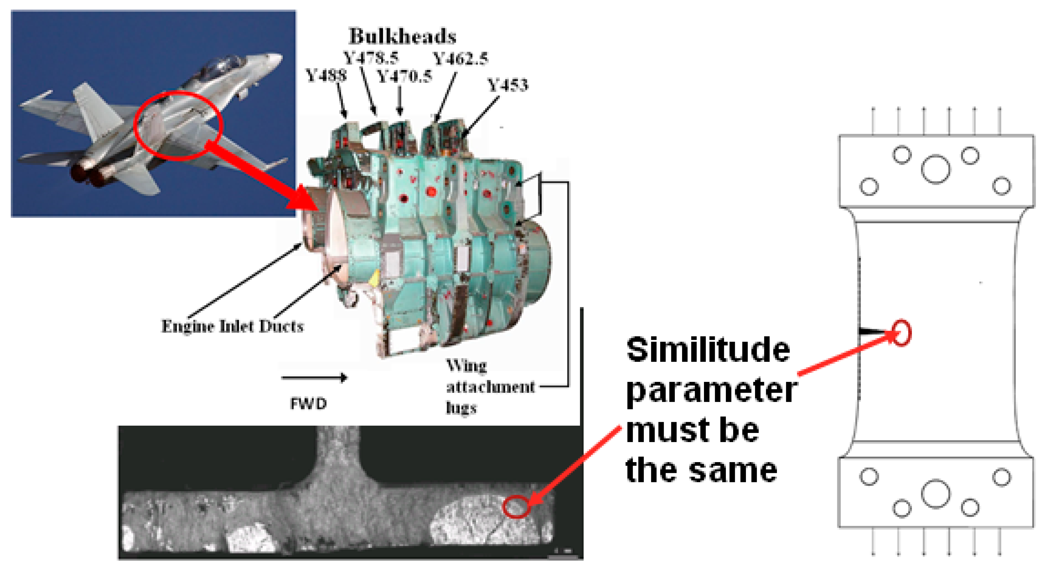
Similitude can be defined as: if two cracks growing in the same material have the same crack tip similitude parameter then their crack growth rates will be the same. A more detailed discussion on the requirement for a valid crack-tip similitude parameter is highlighted in a review paper on the topic of the durability and the damage tolerance of composite and bonded structures [8], as well as in [9] and in Figure 1, where it is noted that without a valid similitude parameter, it is not possible to relate coupon test analysis and data to operational aircraft. In other words, for laboratory tests to yield information that can be directly applicable to operational aircraft, the crack tip similitude parameter in both the aircraft and the laboratory test must be the same. This concept is clarified in Figure 2 via an example of cracking in a Royal Australian Air Force (RAAF) F/A-18 (Classic Hornet) Y488 bulkhead.
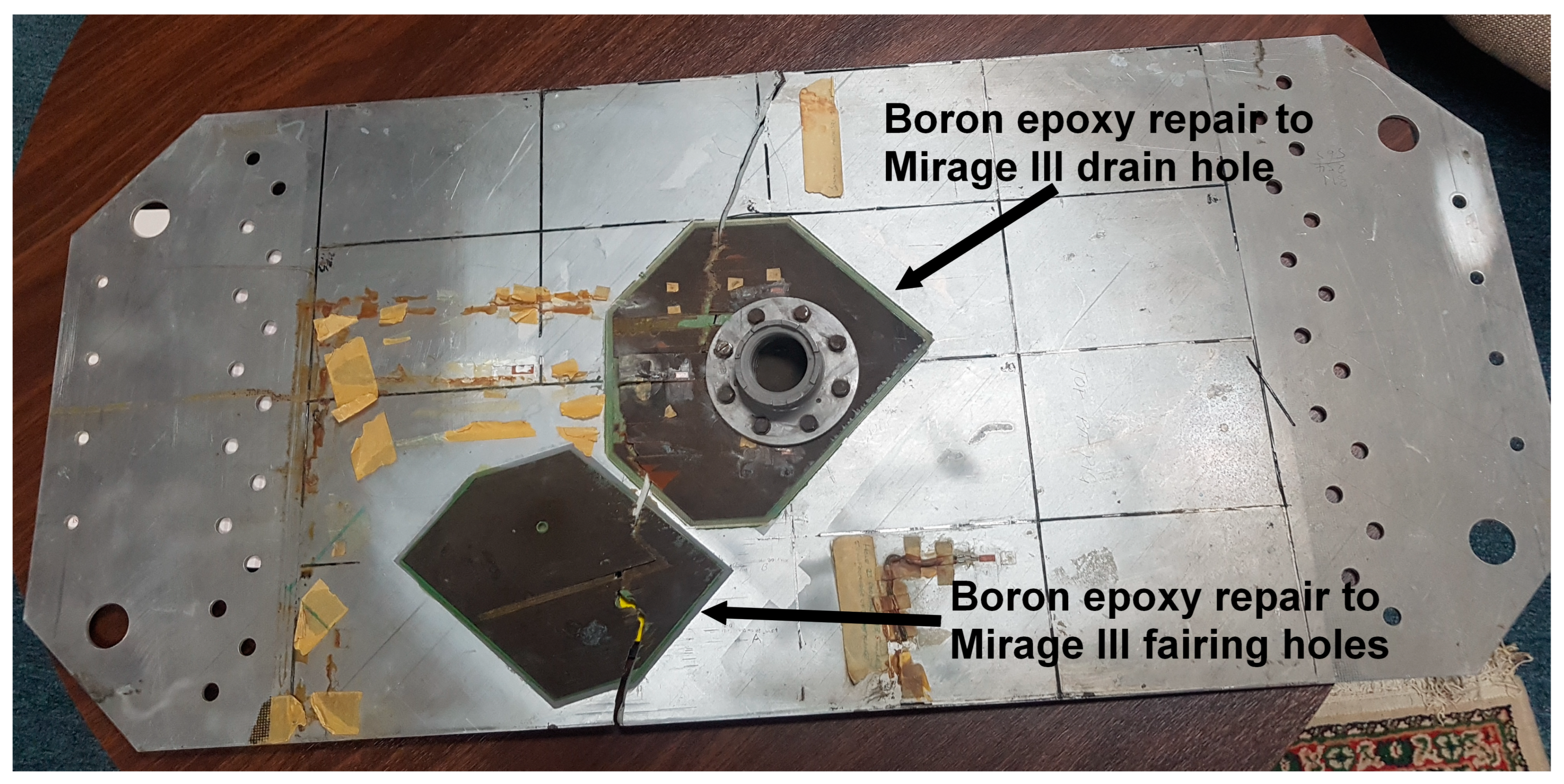
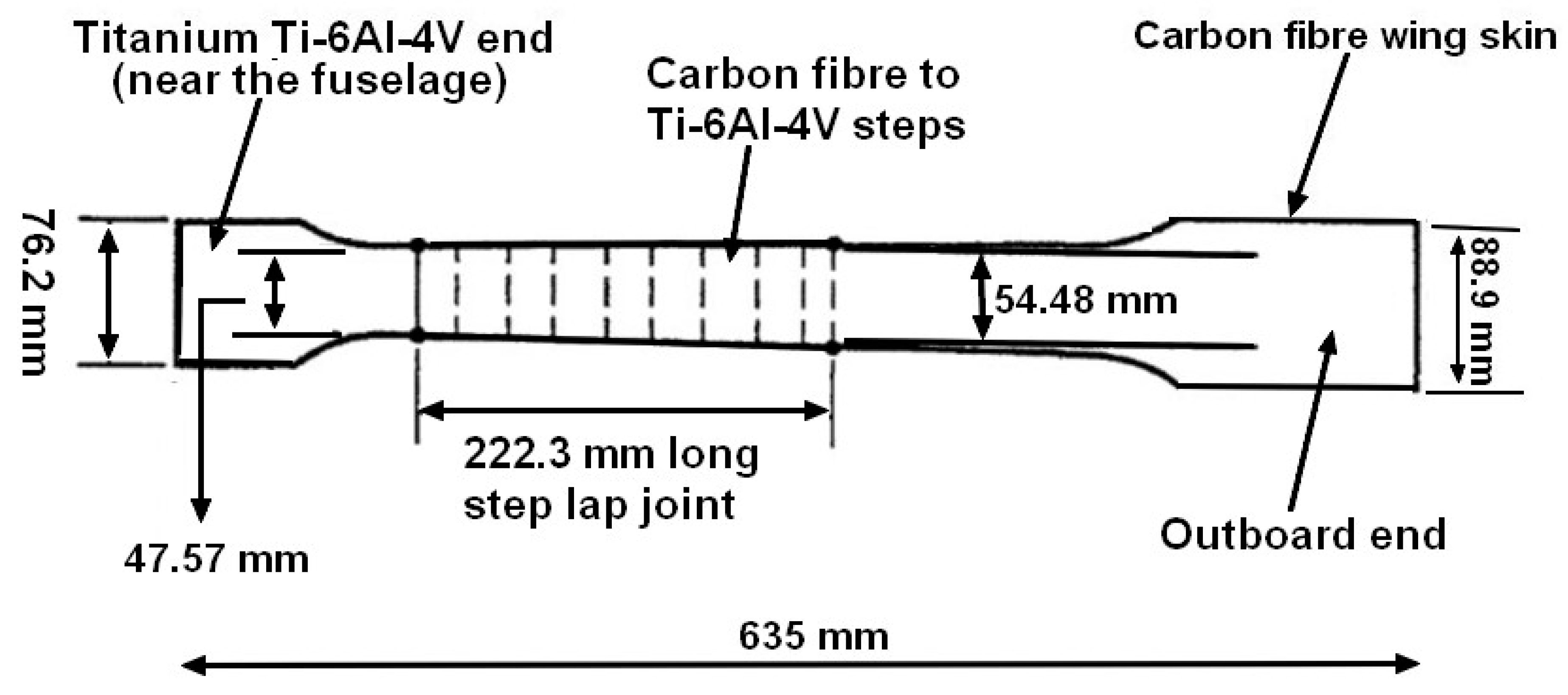
Consequently, if an adhesively bonded airframe, e.g., a bonded doubler or an adhesively bonded repair to an airframe, is found to have a crack in the adhesive then the remaining life of the structure, and/or the repair, needs to be assessed in accordance with the building-block approach shown in Figure 1. As briefly outlined above, this often involves an analytical assessment of the problem/repair coupled with laboratory tests and, dependent on the airworthiness implications, either full-scale testing or tests using representative sub-components are used. The boron-fiber/epoxy composite repair to cracking in the wing pivot fitting of a F-111 aircraft in service with the Royal Australian Air Force (RAAF) [9,10] and the boron-fiber/epoxy composite repair to cracking in a Mirage III fighter aircraft, also in service with the RAAF [11], are examples of where this process was followed. Other examples can be found in [12,13,14,15,16,17] that outline the history and the current status of adhesively bonded doublers/repairs to operational civil and military metallic aircraft. However, as documented in [9,10,11,12,13,14,15,16,17], the laboratory test coupons used to evaluate the effectiveness of bonded repairs are generally limited to uniaxial loads. This is aptly illustrated in Figure 3, which presents a picture of the uniaxial laboratory fatigue test specimen that was used to evaluate the durability of externally bonded boron-fiber/epoxy doublers to the RAAF Mirage III fleet [11], and in Figure 4, which presents a schematic diagram of the uniaxial test specimens [13] is used to assess both the durability of the F/A-18 A-D wing-root step-lap joint for aircraft in service with the US Navy and the static strength of the F/A-18 A-D wing-root step-lap joint for aircraft in service with the RAAF. A range of other examples where uniaxial test specimens were used to evaluate the durability of bonded doublers to the USAF C-141 fleet, the RAAF F-111 fleet, the Canadian CF116, the Federal Express DC-10 and Lockheed Tristar aircraft, and the Airbus A330 fuselage lap joints are given for an example in [12,14,16,17].
With this in mind, the focus of the present paper is to investigate if: For a sustainment analysis of an adhesively bonded joint containing cracking in the adhesive, such as in [13,18], or for the sustainment assessment of a bonded repair the laboratory test program can use simple uniaxial fatigue tests, or whether tests under representative multi-axial operational flight loads are needed. It should be noted that, whilst this paper specifically focuses on adhesively bonded doublers and repairs it also has implications for assessing delamination in operational composite airframes, such as that seen in US Navy F/A-18 Hornet [13,18].

2. Materials and Methods

As discussed above, and further illustrated in [19,20], it is standard practice to use uniaxially loaded test specimens, rather than specimens subjected to multi-axial loads which are representative of those seen in operational aircraft, to evaluate crack growth in aircraft structures. Similarly, it is also standard practice [10,11,12,14,15,16,19,20,21] to use uniaxially loaded specimens, rather than specimens subjected to multi-axial loads, to evaluate the durability of bonded doublers and bonded repairs. Similarly, as outlined in the US Composite Materials Handbook CMH-17-3G [22] bonded joints in both military and civil aircraft are generally designed using the Boeing computer code A4EI [23] that assumes that the joint is only subjected to uniaxial loads. An example of this, and how the design process was validated using uniaxial testing, rather than the actual multi-axial stress states, for the bonded joint in USAF F-15 aircraft is given in [24].
It should also be noted that it has long been known [25,26,27] that the durability analysis of operational aircraft requires a linear-elastic fracture-mechanics analysis that uses the small-crack growth curve, as distinct from curves obtained from tests on long cracks. In this context, it has previously been shown [27,28,29,30,31,32,33,34,35,36,37] that the growth of both long and small cracks in a range of both conventionally and additively manufactured materials subjected to both constant and variable loads can often be accurately modeled using the Hartman–Schijve crack growth equation, viz:
da/dN = Dκ)p,
where p and D are material constants, a is the crack length, N is the number of cycles and Δκ is Schwalbe’s crack driving force [38]:
Δκ = (ΔK − ΔKthr)/(1 − Kmax/A)1/2.
The term Kmax in Equation (2) is the maximum value of the stress intensity factor seen in a load cycle, ∆K = (KmaxKmin), Kmin is the minimum value of the stress intensity factor seen in the cycle, Kmax is the maximum value of stress intensity factor seen in the cycle and A is the cyclic fracture toughness. The term ∆Kthr in Equation (2) represents the “fatigue threshold” below which a crack will not grow, i.e., the value of ΔK for which da/dN = 0.
For the aluminum-alloy, AA7050-T7451 component studied in this paper, when the units of da/dN are in m/cycle and the units of ∆K are MPa√m, the values of D and p used in the analysis presented in this paper, viz: D = 7.0 × 10⁻¹⁰ and p = 2, are taken from [27,28,29,36]. Furthermore, as per [27,28,29,36] when computing the durability of an AA7050-T7451 component the threshold term ΔKthr was taken to be 0.1 MPa√m. Examples of how this approach has been shown to be able to compute the durability of a range of other materials are given in [27,28,29,30,31,32,33,34,36,37].
At this stage, it should be noted that, to the best of the authors’ knowledge, there are no papers in the open literature where the effect of load biaxiality on the growth of small cracks in a metallic component has been studied using a methodology that had previously been shown to accurately represent the growth of small cracks, in the same metal, subjected to uniaxial loads only.
Having investigated the effect of load biaxiality of a simple metallic part, Equation (1) is then modified to investigate its effect on cohesive crack growth in bonded joints, where the adhesive is taken to be a rubber-toughened epoxy film adhesive, i.e., Cytec (Woodland Park, NJ, USA) FM73. In this context, it is known [8,39] that, for cohesive cracking in an adhesive joint, i.e., when crack growth is entirely contained in the adhesive layer, then the square root of the energy release rate, √G, is proportional to K. Consequently, rewriting Equation (2) in terms of √G we obtain:
Δκ′ = (Δ√G − Δ√Gthr)/(1 − √Gmax/√A′)1/2.
The term Gmax in Equation (3) is the maximum value of energy release rate seen in a fatigue (load) cycle and G is defined as:
G = G m a x   G m i n ,
where Gmin is the minimum value of the energy release rate in the load cycle, and A’ is the cyclic fracture toughness. The term Δ√Gthr in Equation (3) represents the “fatigue threshold” below which a crack will not grow, i.e., the value of Δ√G for which da/dN = 0.
Equations (3) and (4) are used since, as has been established in previous papers [8,39], unlike crack growth equations that relate da/dN to simple power law functions of ΔG or Gmax, the term Δκ′ is a valid similitude parameter for representing/modelling the growth of cohesive cracking in adhesive joints.
As such the specific form of the Hartman–Schijve equation used to compute cohesive crack growth in the thin film structural adhesive FM73 is taken from [39], viz:
d a d N = D G G t h r 1 G m a x / A p  
This formulation has been shown to be able to represent the growth of both long and small naturally occurring cohesive cracks. The values of the constants given in [39] for the growth of small naturally occurring cracks in FM73 are given in Table 1. These values are used in the present analysis. Additional studies that illustrate the applicability of this formulation to represent cohesive cracking in adhesives, both Mode I and Mode II, and mixed Modes I and II, and in the nanocomposites that are given in [40,41,42,43].
A key feature of this paper is that, to the best of the authors’ knowledge, there are no papers in the open literature where the effect of load biaxiality on the growth of (cohesive) cracks in the adhesive of an externally bond doubler has been studied using a methodology that had previously been shown to represent the growth of small (cohesive) cracks in a bonded joint, which utilizes the same adhesive, subjected to uniaxial loads.

3. The Importance of Fatigue Testing under the True Operational Multi-Axial Stress State

3.1. Introduction

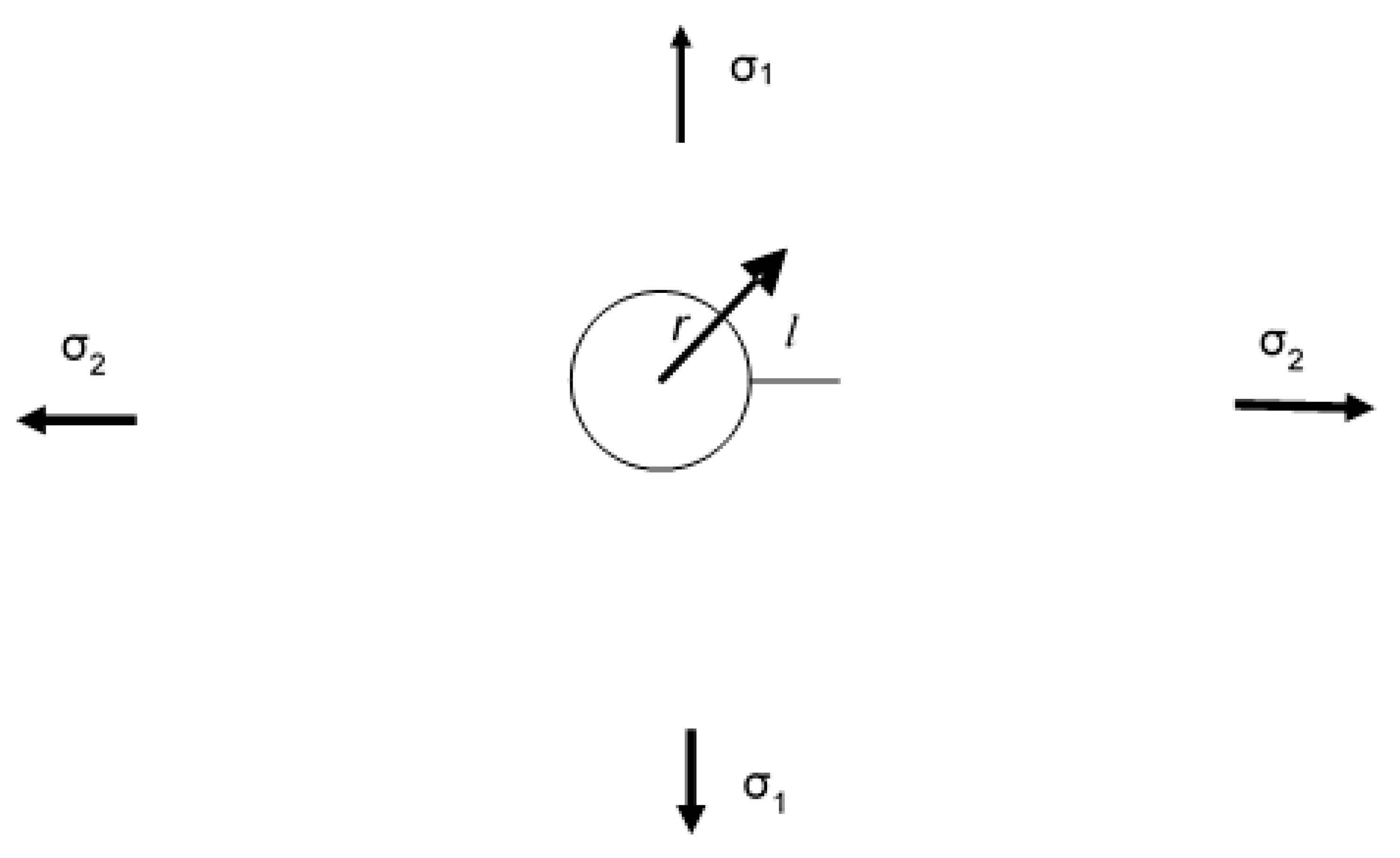
Let us first illustrate the importance of testing under the true multi-axial stress state, rather than simply testing under uniaxial loads. To this end, noting that in the Lockheed study into the durability and damage tolerance of the C-130J [20] the open hole coupon tests were only tested under uniaxial loads, rather than the true multi-axial stress state, let us first consider a large metal panel with a centrally located circular hole where the flight stresses state is biaxial with principal stresses that we will denote as σ1 and σ2, see Figure 5. Let us further assume that the panel contains a small crack of length l emanating from one edge of the hole, see Figure 5. The stress state σ(r), at an arbitrary point along the line of the crack, in the direction perpendicular to the line of the crack in the uncracked panel is given in [44] by the expression:
σ(r) = σ1 (2 + a2/r2 + 3a4/r4)/2 + σ2 (a2/r2 − 3a4/r4)/2.
Here, r is the distance from the center of the hole, a is the radius of the hole and l is the length of the crack as measured from the edge of the hole. It follows from Equation (6) that, for small cracks where l < r, the stress state perpendicular to the line of the crack in the uncracked panel is dependent on both the stress parallel to the crack, σ2, and the stress state perpendicular to the crack, σ1.

3.2. A Simple Worked Example

Now, to evaluate the effect that ignoring σ2 has on crack growth let us consider the case of a centrally located 6 mm diameter hole in an AA7050-T7451 aluminum-alloy panel subjected to maximum remote stresses of σ1 = 150 MPa, σ2 = −150 MPa and R = 0.1. The stress state of σ2 = −σ1 has been chosen so as to mimic that seen by cracks that arose from the fuel-drain hole in Mirage III aircraft in service with the RAAF [11]. For simplicity, the panel was assumed to have an initial crack length of l = 0.01 mm emanating from one side of the central hole, see Figure 5. This crack length was chosen as it is the length recommended in [45] for performing a durability analysis of AA7050-T7451 structural components.
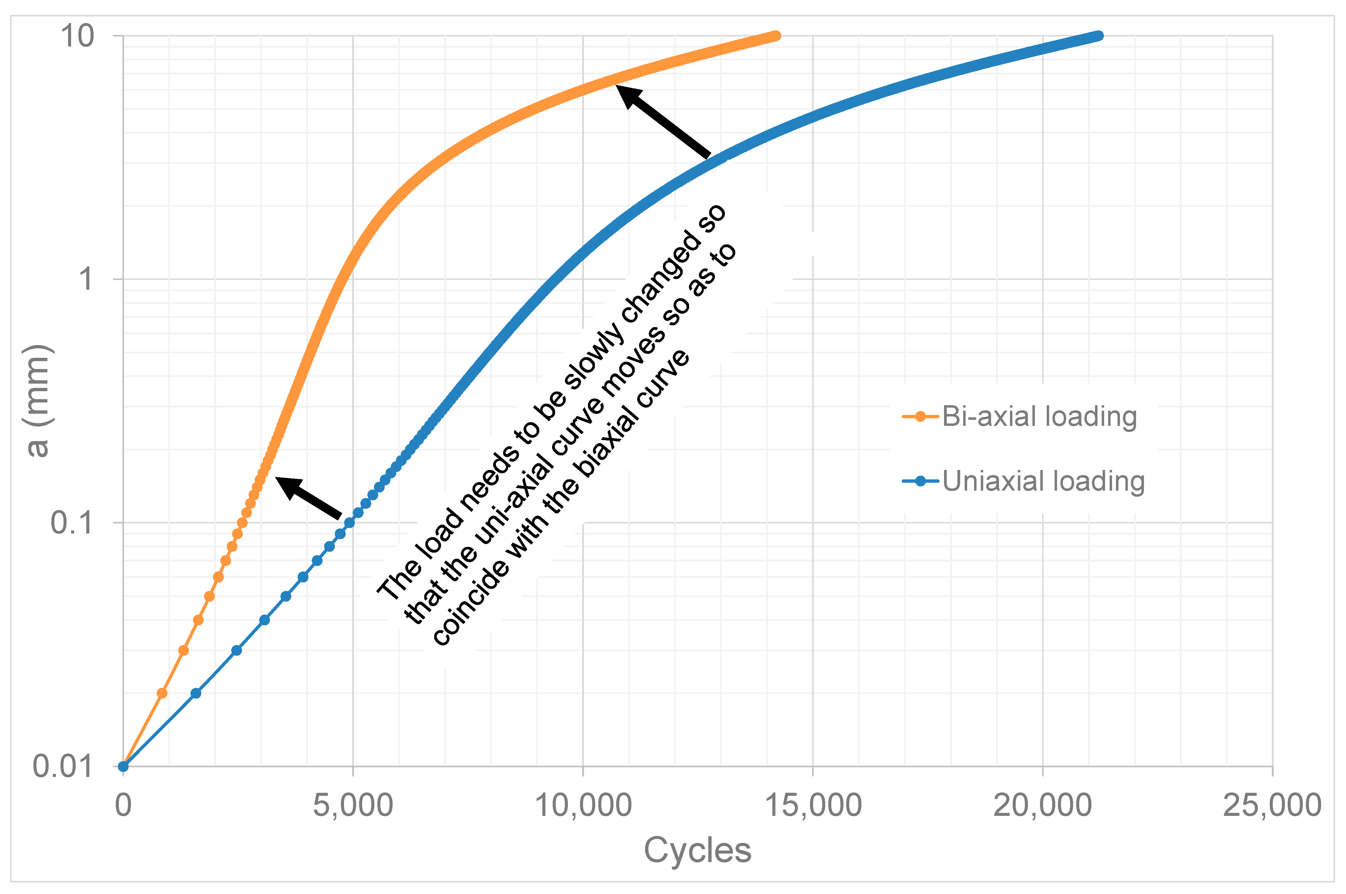
Equations (1) and (2), with the constants D and p as given in Section 2, namely D = 7 × 10⁻¹⁰ and p = 2, were used to study the effect of load biaxiality on the panel shown in Figure 5. (In this analysis the stress intensity factor associated with a given crack length was computed using the stress field given in Equation (6) and the weight function solution for this class of problems that is given in [46]). As in previous studies in [27,28,29,34] involving the growth of small cracks in metallic structures, the term ΔKthr in Equation (2) was set to a small value, i.e., ΔKthr = 0.1 MPa√m. Furthermore, as per [27], the cyclic fracture toughness term was set to be A = 39 MPa√m. The resultant computed crack growth histories for the case of biaxial loading (σ1 = 150 MPa, σ2 = −150 MPa and R = 0.1), and the case when only the uniaxial load (σ1 = 150 MPa and R = 0.1) was considered and are shown in Figure 6.
Figure 6 illustrates that, in this instance, neglecting σ2 (as was conducted in the coupon tests performed by Lockheed to assess the DADT of the Lockheed C-130J wing [20]) results in an erroneous estimate of the crack growth history. Figure 6 also suggests that to ensure that uniaxial coupon tests yield a crack growth history that is consistent with that seen under a multi-axial stress state representative of an operational aircraft, it would be necessary to adjust the applied loads, in the uniaxial test, so that at each crack length the similitude parameter, Δκ, corresponded to that under the multi-axial stress state. To achieve this objective, it requires a valid similitude parameter. As discussed in Section 2, Δκ is one parameter that could be used to achieve this goal.
Noting that the advance of science involves the interplay between theory and observation and that this novel conclusion had never before been hypothesized, the research community is challenged to investigate if this hypothesis can be confirmed.

3.3. Adhesively-Bonded Joints

Whilst the discussion in Section 3.2 has primarily dealt with crack growth in metallic structures it should be noted that, as shown in [47], the load-carrying capacity of a four-step bonded lap joint under combined axial and shear loads, where the shear load was 1/3rd of the axial load, is approximately twenty per cent lower than the same joint subjected to axial loads only. It follows from this finding that the load-bearing capacity of bonded joints subjected to solely uniaxial loads does not necessarily reflect the load-bearing capacity of the joint under representative multi-axial flight loads. When this observation is taken together with the discussion on the durability of a fastener hole under both uniaxial and biaxial loads given in Section 3.2, it also follows that the conclusions drawn from durability tests on bonded joints under uniaxial loads may not necessarily reflect the durability of the joint under representative multi-axial stresses.
The conclusions drawn from the development program [9,10] on the F-111 composite adhesively bonded doubler, where the composite was a boron-fiber reinforced plastic (BFRP), is an excellent example of this phenomenon. In this instance, whilst the uniaxial fatigue tests suggested that the adhesive joint had an excellent durability, of the seventy-eight doublers that were fitted to the RAAF fleet of twenty F-111C aircraft, disbonding in the joint and delamination in the BFRP was found in seven wings. In some instances, the disbonds and delaminations arose between 729 and 1233 flight hours, after being fitted. Furthermore, when detected, the disbonds and delaminations were often fairly extensive [9,10].
Based on above the analysis, it is suggested that to account for not testing under the actual flight stresses it may have been possible to modify the magnitude of the applied fatigue load spectrum. The purpose of this modified approach would be to ensure that, at each stage in the test, the crack tip similitude parameter, Δκ′, see Equation (3), in the adhesive layer in the uniaxial fatigue test was close to that seen in the aircraft. As previously stated, this would require a valid similitude parameter to be identified for the adhesive. Fortunately, as discussed in Section 2, and especially in [8], it is now known that Δκ′ is a valid similitude parameter for representing/modelling the growth of cohesive cracking in adhesive joints.

4. Cohesive Crack Growth in Adhesively-Bonded Double Lap Joints under Uniaxial Loads

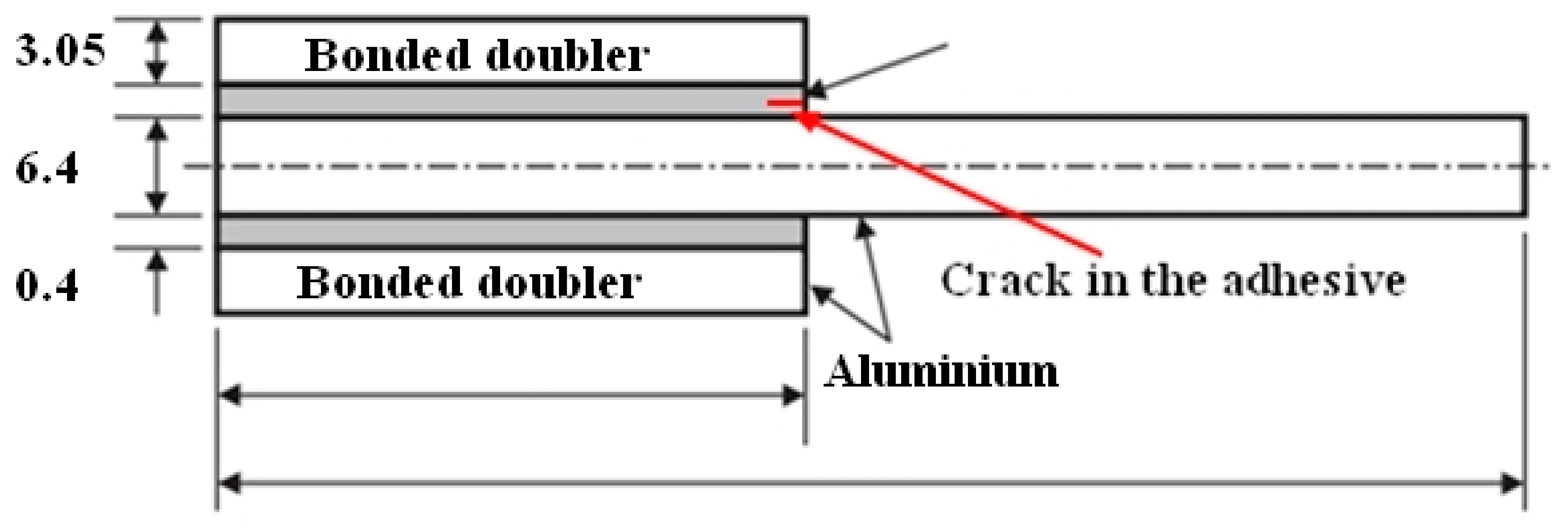
As discussed below, both the methodology used to design bonded repairs to metallic airframes and the methodology and coupon tests used to assess the durability of the bond is generally based on uniaxial analyses and on uniaxial coupon tests. In other words, the effect of the true multi-axial stress state is ignored. Furthermore, as per [13,18,20,21,22,23], the design, the durability analysis and the associated test coupons make extensive use of double overlap joint specimens. Consequently, before we examine the effect of multi-axial stresses on cohesive crack growth in an adhesively bonded doubler, let us first establish that the methodology can accurately compute crack growth in a double overlap joint. To this end, let us first consider the symmetrical over-lap adhesively bonded specimen discussed in [39,48] and shown in Figure 7 where only a uniaxial load is applied. The inner and outer substrates were an AA2024-T3 aluminum-alloy and the adhesive was the hot-cured rubber-toughened film epoxy FM73 (Cytec, USA). Reference [48] reported that a fatigue crack was observed to nucleate, and grow cohesively, in the adhesive layer from naturally occurring defects which were present in the adhesive layer.
The Young’s modulus and Poisson’s ratio associated with both the FM73 adhesive and the AA2024-T3 plate and doublers are listed in Table 2. These values are taken from [39,48]. The inner aluminum-alloy substrate was 400 mm long and 6.4 mm thick, see Figure 7. The outer aluminum-alloy substrates were 200 mm long and 3.05 mm thick. The FM73 adhesive layer was 0.4 mm thick. The specimen was symmetrical with a width of 20 mm. The test spectrum consisted of 93,000 cycles, at a frequency of 3 Hz, of constant amplitude loading, where the remote stress in the aluminum alloy was varied from 0 to 193 MPa.
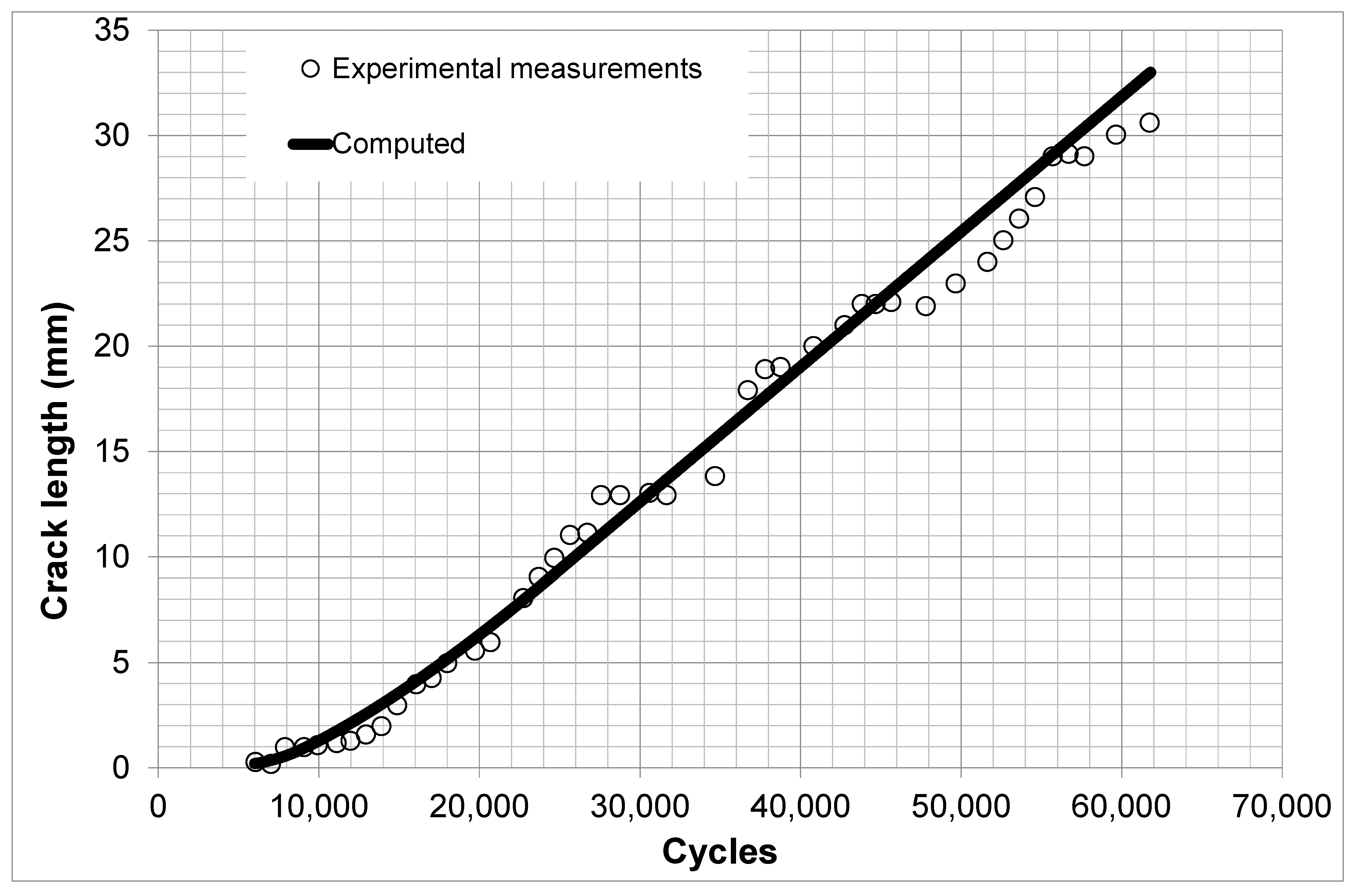
This problem is now analyzed using the Zencrack software version 9.3-1 (e.g., [49,50,51,52,53,54,55]) added to the ABAQUS® finite element computer code, see Appendix A for more details. A comparison between the computed, by Zencack using Equation (5) using the values of D, p, A′ and G t h r given in Table 1, and measured crack growth histories is shown in Figure 8 where we see excellent agreement. The initial crack size in this analysis is approximately 0.2 mm.

5. Cohesive Crack Growth in Adhesively-Bonded Doublers under Uniaxial and Biaxial Loads

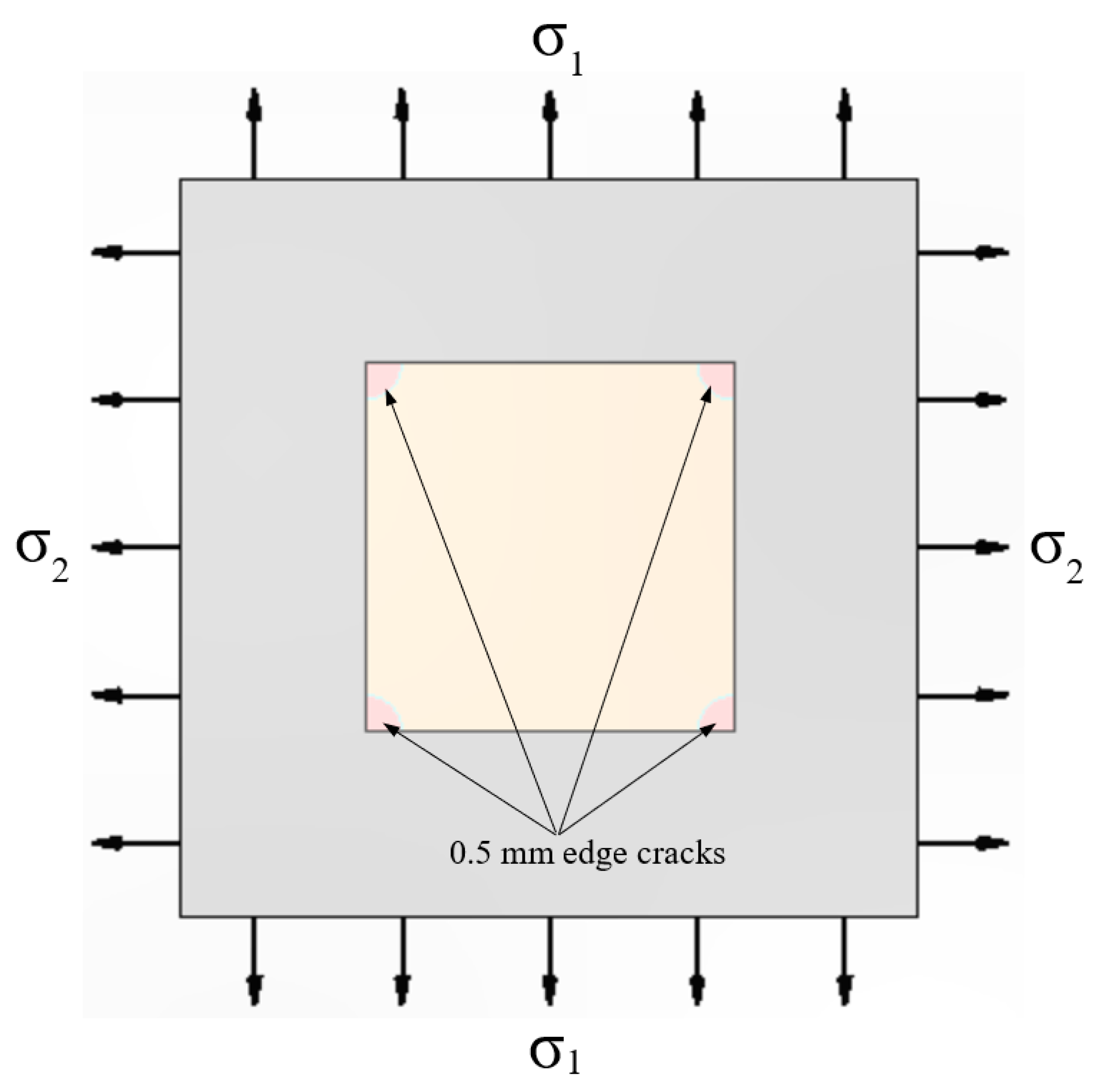
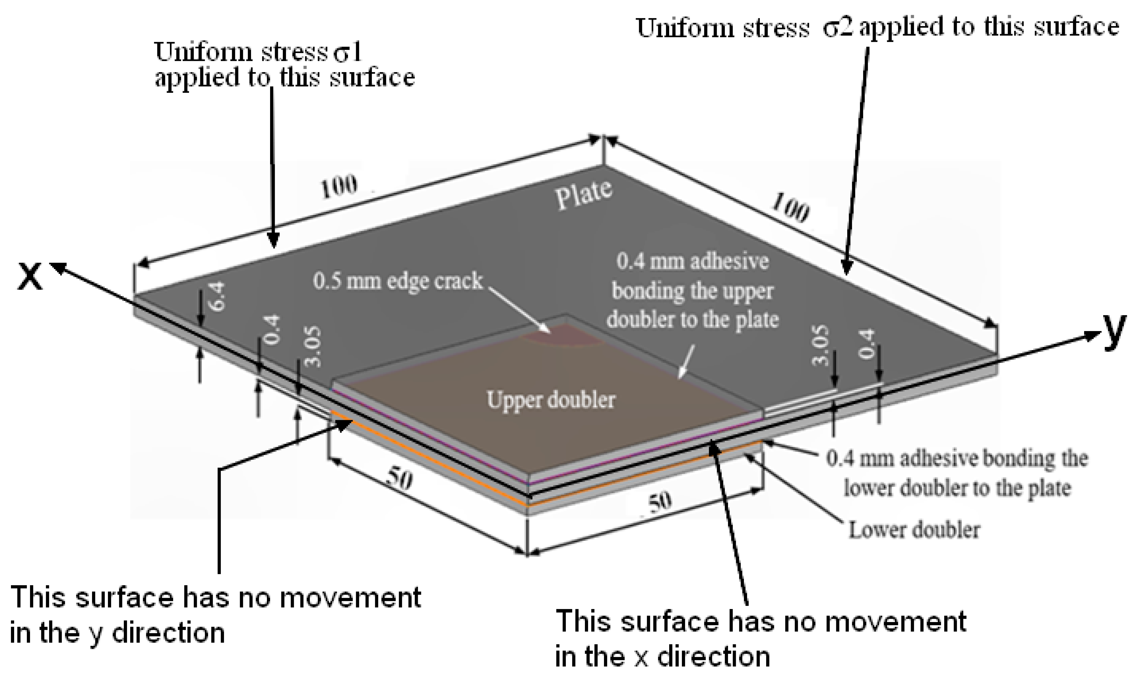
Having established the ability to accurately compute the growth of small sub mm cohesive cracks in this adhesive using Zencrack and the Hartman–Schijve crack growth equation for this adhesive, and thereby validated our theoretical methodology, let us next consider the problem of the growth of small three-dimensional (3D), cohesive quadrant cracks with a 0.5 mm radius in the adhesively bonded doubler specimen shown in Figure 9. Furthermore, as noted above, having established the ability of Zencrack to accurately model the cohesive crack growth under uniaxial loads, let us next assess the effect of multi-axial loads on the life of a bonded joint that contains such 3D disbonds.
One reason for studying this particular problem is that the laboratory tests commonly used to evaluate the effect of an adhesive disbond on the remaining life of a bonded joint are generally restricted to specimens tested under uniaxial loads. However, the stress state seen by a bonded joint on an operational aircraft is generally multi-axial. This raises the question:
‘How does the growth of sub mm cracks in an adhesive bond subjected to uniaxial loads relate to growth under multi-axial loads?’
To address this question let us consider a large square AA2024-T3 aluminum-alloy (6.4 mm thick) plate where the planar dimensions of the plate are 200 mm by 200 mm, see Figure 9 and Figure 10. The plate has two identical centrally located square AA2024-T3 aluminum-alloy 3.05 mm doublers, one is adhesively-bonded to its upper surface and the other is bonded to its lower surface, again see Figure 9 and Figure 10. The doublers were bonded using the 0.4 mm thick FM73 film adhesive.
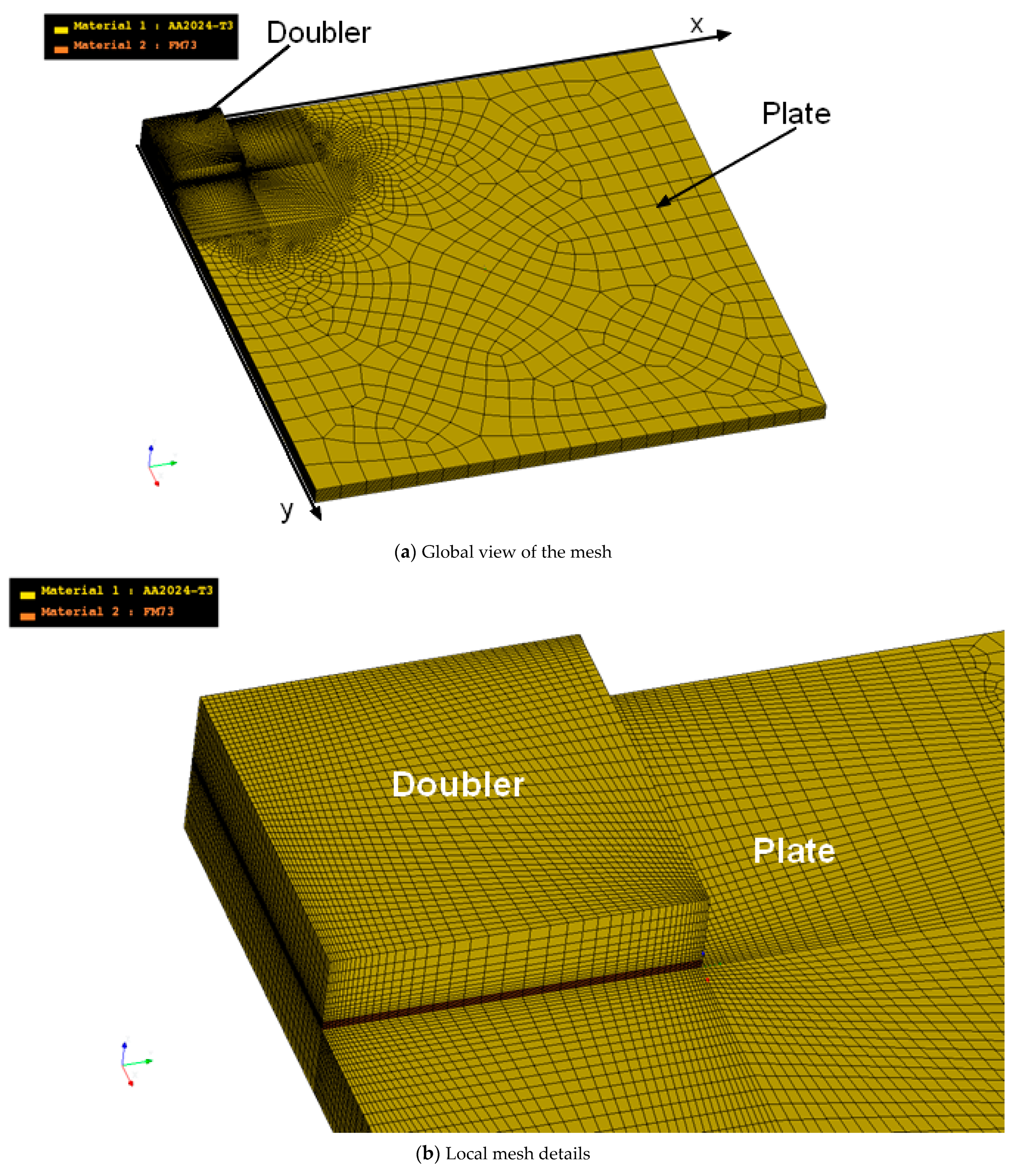
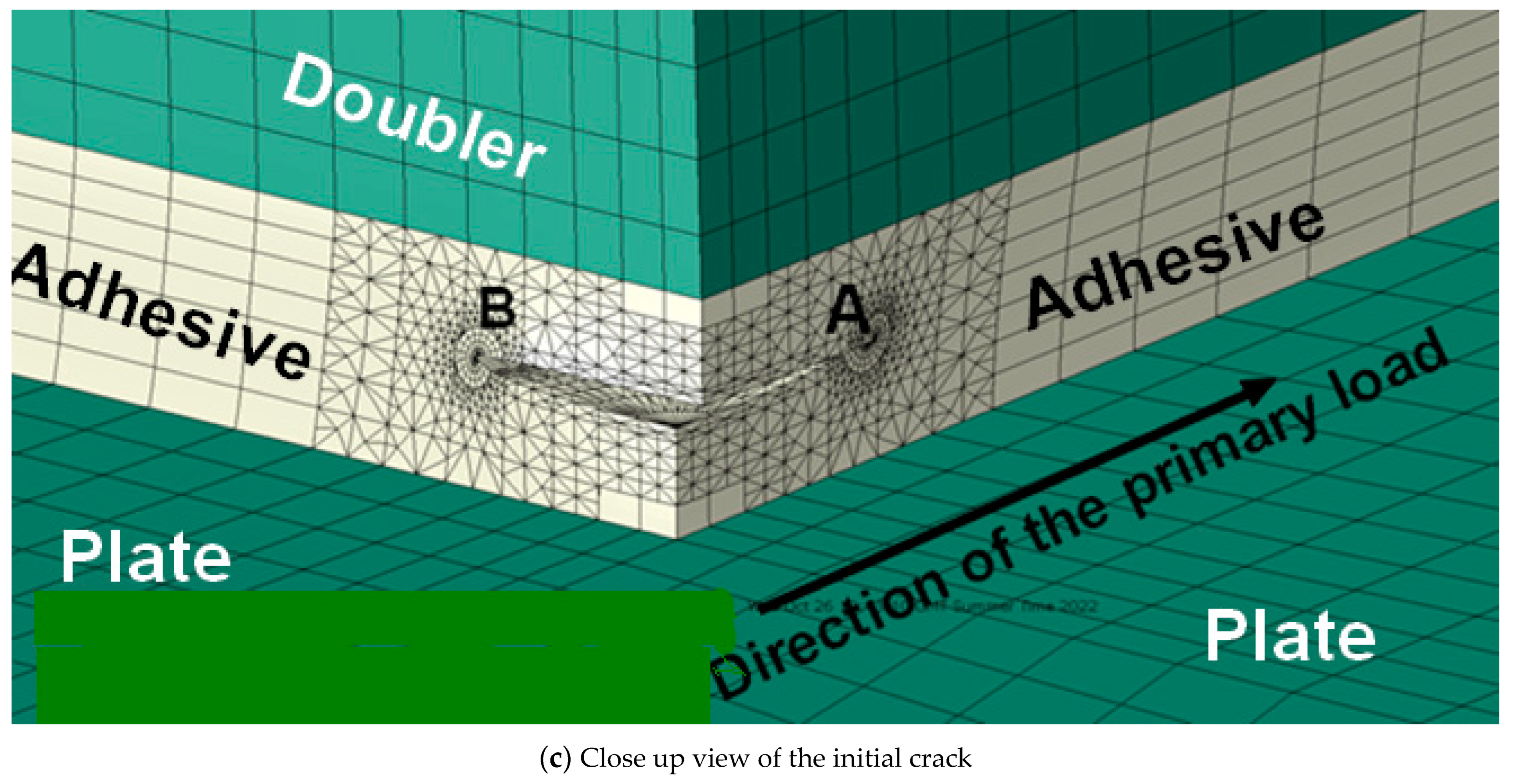
The analysis assumes that 0.5 mm radius quadrant fatigue cracks grow cohesively through the adhesive layer and that these cracks arose from naturally occurring defects, which were present in the adhesive layer at all of the edges in both the upper and lower doublers, see Figure 9 and Figure 10. (This size initial crack was chosen since it represents a reasonable lower bound estimate of the size that could be realistically found in an operational structure [27,39].) It is also assumed that the fatigue cracks in the specimen were located in identical positions in both the upper- and the lower-doublers, and that the growth of all of these corner cracks was identical. (This assumption allows the problem to be analyzed using symmetry considerations, see Figure 10 which also shows the boundary conditions used in the analyses.) It should also be noted that, as shown in Figure 11, away from the adhesive was modeled using seven elements through its thickness. The mesh used in the vicinity of the crack was significantly finer and this fine mesh moved as the crack grew.
The specimen was assumed to be subjected to three different R = 0.0 constant amplitude load spectra, viz:
(i)
Uniaxial constant amplitude fatigue stresses with the peak stresses in the spectrum being σ1 = 193 MPa and σ2 = 0.
(ii)
Biaxial constant amplitude fatigue stresses with the peak stresses in the spectrum being σ1 = 193 MPa and σ2 = σ1/3.
(iii)
Biaxial constant amplitude fatigue stresses with the peak stresses in the spectrum being σ1 = 193 MPa and σ2 = −σ1/3.
The value of the remote stress σ1 = 193 MPa was chosen to coincide with that in Section 3. As previously stated, the governing equation for the FM73 adhesive was taken to be as given by Equation (5), with the values of the constants as given in Table 2.
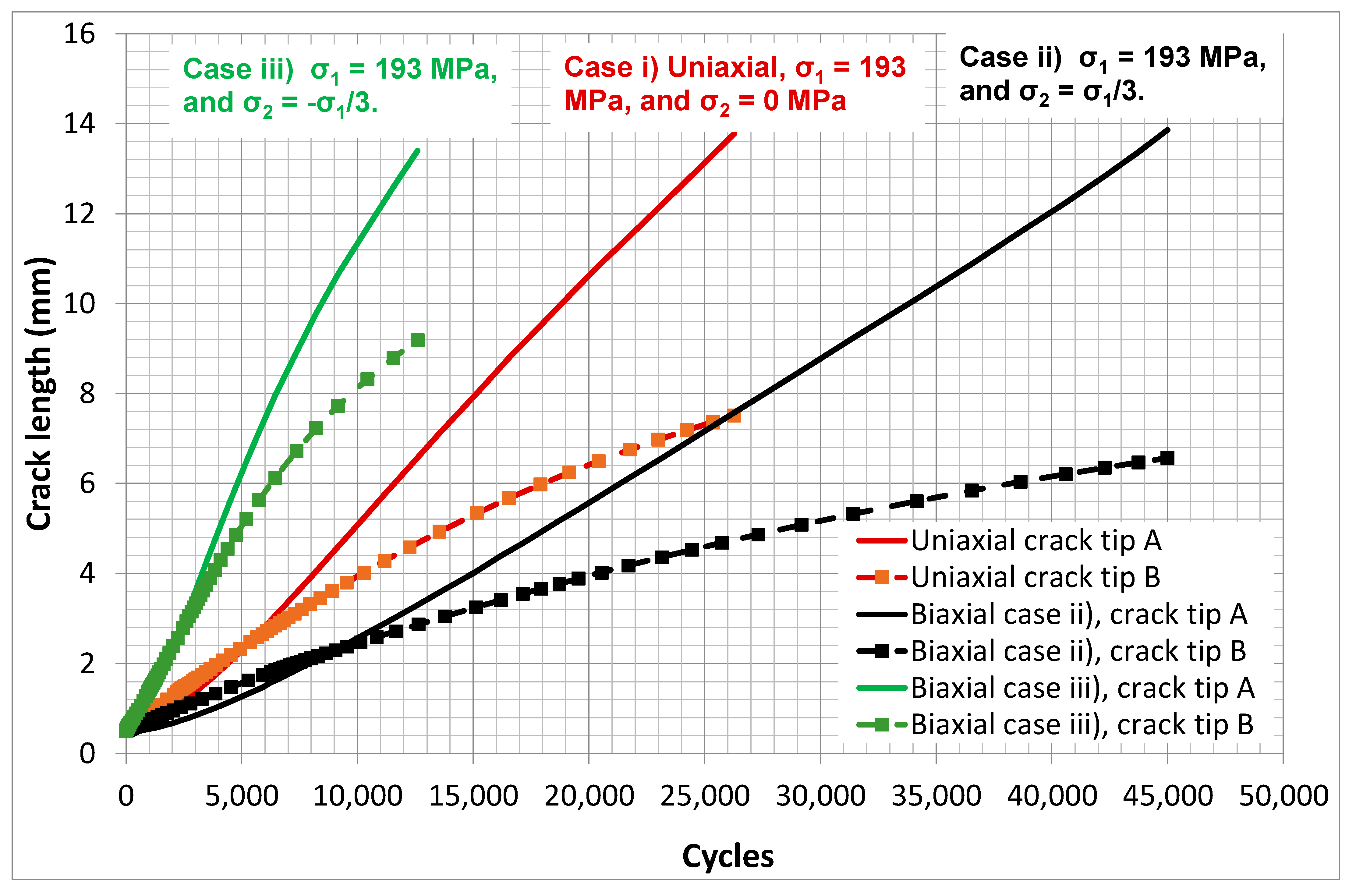
Details of the mesh used in these analyses are shown in Figure 11. The resultant crack growth histories for both the uniaxial and two biaxial load cases are shown in Figure 12. (Here, it should be noted that the location of the crack tips labeled A and B in Figure 12 are given in Figure 11. It should also be noted that in these analyses the shape of the (cohesive) crack front was allowed to evolve naturally. To the best of the authors’ knowledge, this level of complexity has not previously been attempted.) Here, we see that the three crack growth histories differ significantly. Interestingly, in this example, the uniaxial loads would appear to be more severe than the biaxial load case (ii), namely σ1 = 193 MPa and σ2 = σ1/3 and less severe than the biaxial load case (iii), i.e., σ1 = 193 MPa and σ2 = −σ1/3.

6. Cohesive Crack Growth in Adhesively-Bonded Joints under a Combat Aircraft Flight Load Spectrum

Whilst most bonded joints/doublers/repairs in current operational aircraft are based on a “no crack growth” design approach [22], the results in [8,39,47] revealed that, when subjected to operational flight loads, disbonding and disbond growth can nevertheless occur in bonded structures. This raises the question of what is the effect of load biaxiality on the remaining life of an adhesively bonded joint with a known existing disbond under a representative flight load spectrum. To address this question, we now study the effect of load biaxiality on the remaining life of the joint shown in Figure 9 and Figure 10 subjected to the industry standard combat aircraft flight load spectrum FALSTAFF [56,57,58,59], which is a repeated load-block spectrum with each load block consisting of approximately 9000 cycles and where each load block represents 200 flights.
Three different load cases were analyzed again using Zencrack and the Hartman–Schijve crack growth equation for this adhesive, viz:
(i)
The peak stresses in the spectrum are σ1 = 193 MPa and σ2 = 0.
(ii)
The peak stresses in the spectrum are σ1 = 193 MPa and σ2 = σ1/3.
(iii)
The peak stresses in the spectrum are σ1 = 193 MPa and σ2 = −σ1/3.
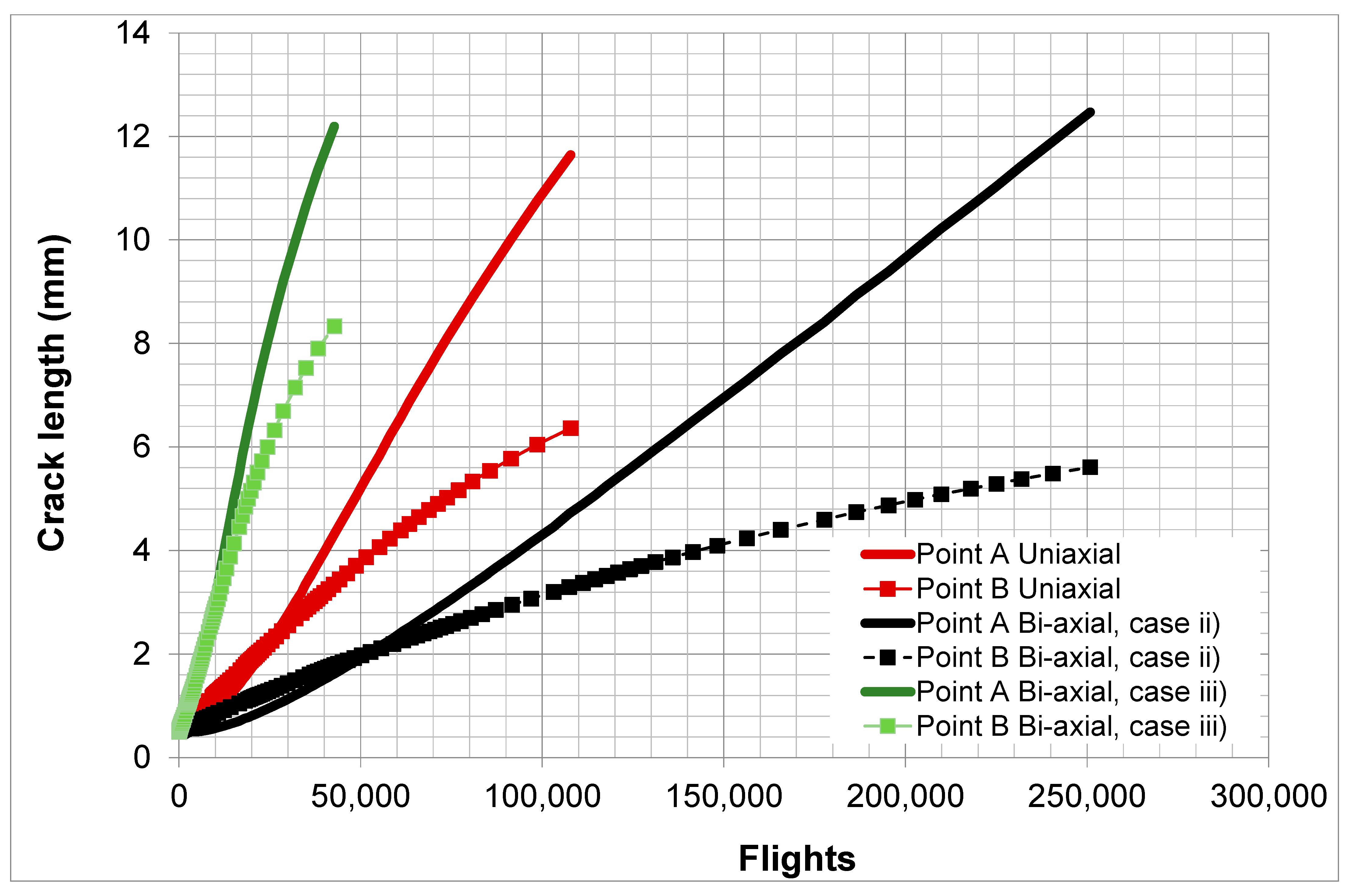
The resultant computed crack growth curves are shown in Figure 13.
Figure 13 suggests that:
(i)
The effect of biaxial loads on crack growth under operational flight loads can be significant.
(ii)
When comparing the results shown in Figure 12 and Figure 13, we see that the relative effect of the biaxial stresses on crack growth is similar regardless of whether the fatigue load spectra is a constant amplitude spectrum, as in Figure 12, or a FALSTAFF flight load spectrum, as in Figure 13. By this we mean that case (iii) had faster crack growth than the uniaxial load case, i.e., case (i), and that case (ii) had slower crack growth than the uniaxial load case. This observation reflects the way in which the various stress states interact with the disbond, i.e., with the crack in the adhesive.

7. Conclusions

Roach et al. [12] presented guidelines for the design of laboratory test specimens for assessing the airworthiness of adhesively bonded repairs/doublers to aging (metallic) aircraft and for designing against disbonding of the repair/doubler. These design guidelines were followed in [10,12] which present case studies associated with externally bonded repairs/doublers to a range of operational aircraft. However, these guidelines are based on the use of uniaxial test specimens. Indeed, such test specimens are commonly used to assess the durability of both externally bonded doublers and bonded joints. However, the present paper suggests that to obtain realistic estimates for the life of a bonded doubler/repair, and hence determine the necessary inspection intervals, it is best to test under representative multi-axial operational flight loads.
It should be stressed that this is not currently done. It should also be stressed that, as noted in NASA Fracture Control Handbook NASA-HDBK-5010, even for aerospace-quality metallic structures the variability in the crack growth curves is such that sufficient tests need to be performed in order to obtain the worst-case crack growth curve. As a result, since full scale testing is generally confined to a single airframe, the laboratory coupon test program should ensure that sufficient tests are performed so that the worst-case (performance) can be captured.
In the present paper we have validated our proposed theoretical model for the case of uniaxially loaded adhesively bonded joints, see Figure 8. However, to the authors’ knowledge no such experimental data exists for the case of bonded joints, doublers or repairs under multi-axial loading, which is very difficult and lengthy to obtain, and which needs very specialized test equipment. Therefore, in this context, we would make three important points:
(i)
Firstly, it should be noted that an essential requirement of any such laboratory test program that is performed so as to determine inspection intervals/durability of an adhesively bonded repair/doubler. Regardless of whether uniaxial or biaxial laboratory tests are performed, it is necessary to establish that at each stage in the testing regime the LEFM similitude parameter in the test specimen corresponds to that in the (operational) airframe.
(ii)
Secondly, the results of the present study have led to the hypothesis that: For uniaxial coupon tests to yield a crack growth history that is consistent with that seen under a multi-axial stress state representative of an operational aircraft, it may be necessary to adjust the magnitude of the applied loads as the crack grows such that at each crack length the similitude parameter, i.e., Δκ′, in the uniaxial test corresponds to that present under the true multi-axial stress state. The scientific community is challenged to evaluate the potential/validity of this hypothesis.
(iii)
Thirdly, a simpler, but possibly less desirable, approach, that is consistent with the building block approach to certification delineated in MIL-STD-1530D and JSSG-2006 and with the approaches outlined in [10,12,15], is to first establish that you can compute both the uniaxial and the multi-axial test crack histories in specimens, albeit with geometries and support conditions that may not be truly representative of the operational structure, using the same input parameters in both cases. (By this it is meant that the crack growth equation used in both studies would be identical, and that there would be no disposable parameters that could be “tweaked” to improve the fit to the experimental data.) Having thus validated the analysis methodology, the engineer would then run the analysis using a finite element model that has the actual geometry, boundary conditions, operational flight loads, etc., and compute the in service performance, i.e., the remaining life, inspection intervals, etc.

Author Contributions

R.J.: Formal Analysis; Methodology; Software; Original Draft Preparation; Writing; Supervision. R.C.: Formal Analysis; Software; Review & Editing. C.T.: Formal Analysis; Software; Review & Editing. A.J.K.: Methodology; Writing of the manuscript; Review & Editing. D.P.: Data Curation; Formal Analysis; Software; Review & Editing. All authors have read and agreed to the published version of the manuscript.

Funding

This study did not receive external funds.

Data Availability Statement

The data will be made available upon request.

Conflicts of Interest

The authors declare no conflict of interest.

Appendix A

The above data was analyzed using the Zencrack® [49,50,51,52,53,54,55] software interface version 9.3-1 to the ABAQUS® (version 9.3.1) finite element code. Zencrack is a fracture mechanics-based 3D crack propagation simulation software which is interfaced to a number of commercial finite-element analysis (FEA) codes. It allows calculation of fracture mechanics parameters such as energy release rate and stress intensity factors via automatic generation of focused cracked meshes from uncracked finite element models.
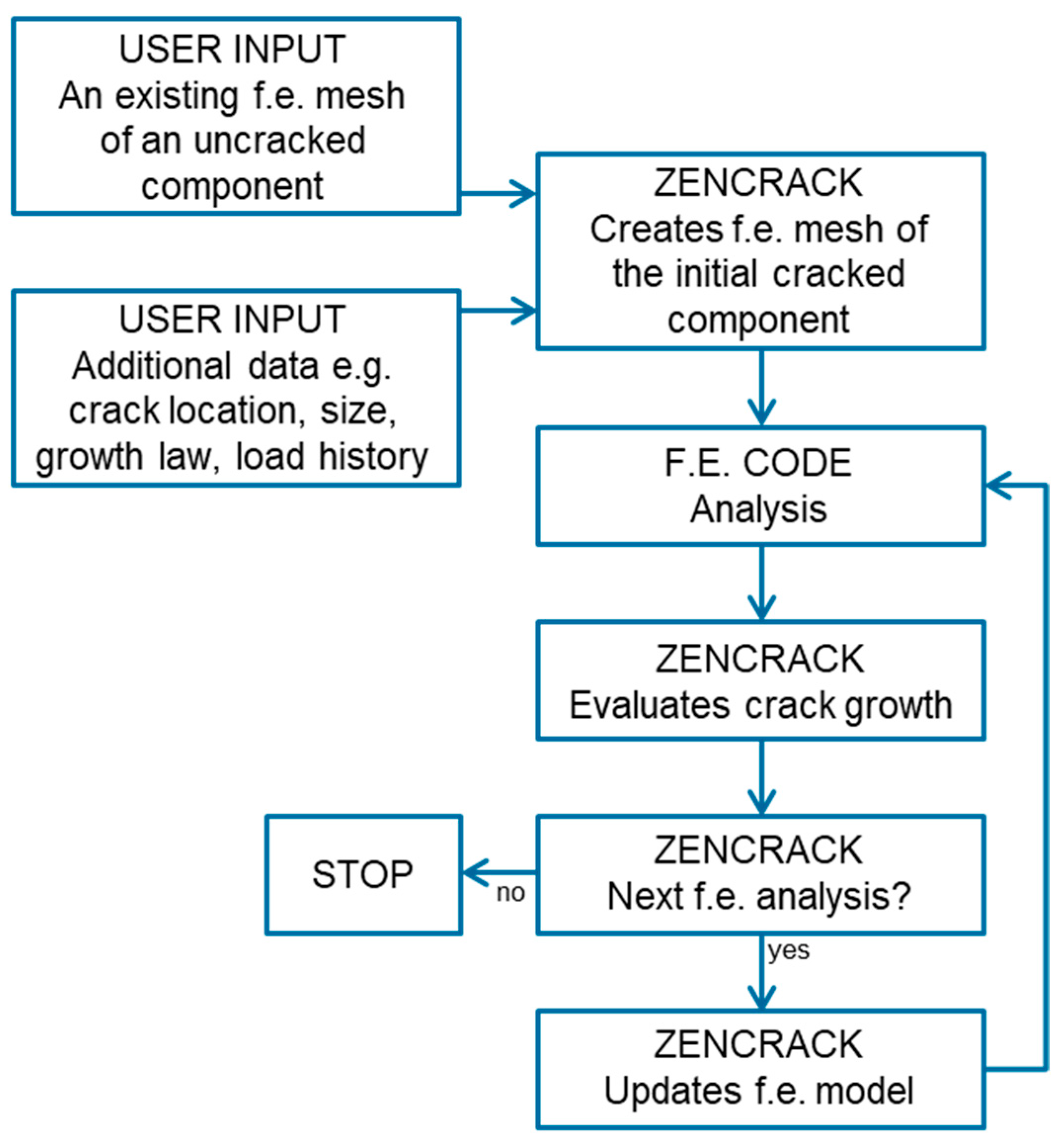
A high-level overview of the Zencrack® process is shown in the flowchart in Figure A1. This iterative process continues to advance the crack until certain criteria are satisfied, see [49,50,51] for details.
Zencrack inserts a crack of the given shape and size at a given location in the supplied finite element model of the uncracked component. This process creates a finite element mesh of the cracked component with rings of hexahedral elements providing a fully focused mesh along the crack front. The re-meshing method in Zencrack® is able to perform this process with minimal requirements placed on the meshing within the uncracked mesh. Indeed, the initial crack definition is geometry based and, as such, is mesh independent. Updates to loads and boundary conditions in the re-meshed region are carried out as necessary.
An analysis is then performed by the finite element code and various fracture mechanics parameters calculated (e.g., stress intensity factors, energy release rates and/or J-integral depending upon the analysis requirements). Loading cases applied in the FEA can be a simple static load or a time-varying, load both with or without thermal variations. For fatigue crack propagation, it is essential that the loads in the FEA are related to the load sequence that will be used for crack growth integration. Zencrack performs this correlation through a load system methodology with the simplest fatigue scenario being constant amplitude loading. Having identified fracture mechanics parameters at each crack-front node and a load sequence for integration, this information is combined with a crack growth law to obtain an advanced position for each crack front node with all nodes having the same time increment or number of load cycles. Since integration of each node is handled separately in terms of both magnitude and direction of growth the process allows for non-planar development of the crack front.
The allowed amount of crack growth at each step is monitored during the analysis to prevent instability of the crack shape that can be caused by trying to use steps that are too large. The new crack front is trimmed to the model surface, the mesh is updated with the new crack front and analysed once again using the finite element code. This process repeats to further advance the crack until certain criteria are satisfied.
Zencrack has a number of built-in crack growth equations/methods that can be used when performing a fatigue-crack growth analysis, viz: Paris, Walker, Foreman, Hartman-Schijve and tabular. The software also allows for other growth equations via a user subroutine facility.
Figure A1. Crack propagation fracture mechanics software interaction with the FEA software version 9,3-1.
Aerospace 10 00946 g0a1
In the present analysis, the crack is not constrained to propagate in any particular direction. At each crack, the front node in the normal plane a series of virtual crack extensions at different angles are tested and the direction in which the maximum energy release rate is produced is selected for the virtual crack extension. This allows the crack to grow in 3D space in the maximum energy release rate direction and is not constrained to remain in the adhesive midplane. More details can be found in [49,50,51].

References

  1. MIL-STD-1530D. Department of Defense Standard Practice; Washington, DC, USA. 2016. Available online: http://everyspec.com/MIL-STD/MIL-STD-1500-1599/MIL-STD-1530D_55392/#:~:text=%2DAUG%2D2016)-,MIL%2DSTD%2D1530D%2C%20DEPARTMENT%20OF%20DEFENSE%20STANDARD%20PRACTICE%3A,while%20managing%20cost%20and%20schedule (accessed on 3 November 2023).
  2. Griffith, A.A. The phenomena of rupture and flow in solids. Philos. Trans. R. Soc. 1920, A221, 163–198. [Google Scholar]
  3. Irwin, G.R. Analysis of stresses and strains near the end of a crack traversing a plate. J. Appl. Mech. 1957, 24, 361–364. [Google Scholar] [CrossRef]
  4. Paris, P.C. A brief history of the crack tip stress intensity factor and its applications. Meccanica 2014, 49, 759–764. [Google Scholar] [CrossRef]
  5. Department of Defense Joint Service Specification Guide, Aircraft Structures, JSSG-2006. October 1998. Available online: http://everyspec.com/USAF/USAF-General/JSSG-2006_10206/ (accessed on 3 November 2023).
  6. Gallagher, J.P.; Giessler, F.J.; Berens, A.P.; Wood, H.A. USAF Damage Tolerant Design Handbook: Guidelines For The Analysis and Design of Damage Tolerant Aircraft Structures, Revision B. AFWAL-TR-82-3073. Wright-Patterson Air Force Base, Ohio 4543. May 1984. Available online: https://apps.dtic.mil/sti/citations/ADA153161 (accessed on 3 November 2023).
  7. Kruse, T.; Körwien, T.; Geistbeck, M.; Schmid Fuertes, T.A. Fatigue behaviour and damage tolerant design of composite bonded joints for aerospace application. In Proceedings of the 20th International Conference on Composite Materials, Copenhagen, Denmark, 19–24 July 2015; Available online: https://www.iccm-central.org/Proceedings/ICCM20proceedings/papers/paper-2219-1.pdf (accessed on 6 November 2023).
  8. Jones, R.; Kinloch, A.J.; Michopoulos, J.; Iliopoulos, A.P. Crack growth in adhesives: Similitude and the Hartman-Schijve equation. Compos. Struct. 2021, 273, 114260. [Google Scholar] [CrossRef]
  9. Jones, R.; Peng, D. A Building Block Approach to Sustainment and Durability Assessment: Experiment and Analysis. In Comprehensive Structural Integrity, 2nd ed.; Aliabadi Ferri, M.H., Soboyejo, W., Eds.; Elsevier: Oxford, UK, 2023; Volume 7, pp. 73–101. ISBN 978-0-12-822944-6. [Google Scholar]
  10. Molent, L.; Jones, R. The F111C wing pivot fitting repair and implications for the design/assessment of bonded joints and composite repairs. In Aircraft Sustainment and Repair; Chapter 10, 511–543; Jones, R., Baker, A.A., Matthews, N., Champagne, V., Jr., Eds.; Butterworth-Heinemann Press: Oxford, UK, 2018; ISBN 9780081005408. [Google Scholar]
  11. Baker, A.A.; Callinan, R.; Davis, M.; Jones, R.; Williams, J. Repair of Mirage III aircraft using the BFRP crack-patching technique. Theor. Appl. Fract. Mech. 1984, 2, 1–16. [Google Scholar] [CrossRef]
  12. Roach, D.; Rackow, K. Development and Validation of Bonded Composite Doubler Repairs for Commercial Aircraft. In Aircraft Sustainment and Repair; Sandia Report SAND2007-4088, July 2007; Chapter 11; Jones, R., Matthews, N., Baker, A.A., Champagne, V., Jr., Eds.; Butterworth-Heinemann Press: Oxford, UK, 2018; pp. 545–743. ISBN 9780081005408. [Google Scholar]
  13. Seneviratne, W.P.; Tomblin, J.S.; Cravens, T.; Kittur, M.; Rahman, A. Durability and Residual Strength Assessment of F/A-18A-D Durability and Residual Strength Assessment of F/A-18A-D Wing­Root Stepped-Lap Joint. In Proceedings of the AIAA Centennial of Naval Aviation Forum “100 Years of Achievement and Progress”, Virginia Beach, VA, USA, 21–22 September 2011. [Google Scholar] [CrossRef]
  14. Mazza, J.; Storage, K.M. Bonded Repair in the United States Air Force and Work to Expand Future Capability. In AGARD STO Meetings Proceedings, STO-MP-AVT-266, Use of Bonded Joints in Military Applications; Paper 4; 2018; pp. 4-1–4-20. ISBN 978-92-837-2172-7. Available online: https://www.sto.nato.int/publications/STO%20Meeting%20Proceedings/STO-MP-AVT-266/MP-AVT-266-04.pdf (accessed on 6 November 2023).
  15. Baker, A.A.; Wang, J. Adhesively Bonded Repair/Reinforcement of Metallic Airframe Components: Materials, Processes, Design and Proposed Through-Life Management. In Aircraft Sustainment and Repair; Chapter 6; Jones, R., Matthews, N., Baker, A., Champagne, V., Eds.; Butterworth-Heinemann Press: Oxford, UK, 2018; pp. 191–252. ISBN 9780081005408. [Google Scholar]
  16. Raizenne, D. Case History: CF116 Upper Wing Skin Fatigue Enhancement Boron Doubler. In Advances in the Bonded Composite Repair of Metallic Aircraft Structure; Chapter 36; Baker, A., Rose, L.R.F., Jones, R., Eds.; Elsevier Applied Science Publishers: Amsterdam, The Netherlands, 2002. [Google Scholar]
  17. Chalkley, P.D.; Wang, C.H.; Baker, A.A. Chapter 5, Fatigue Testing of Generic Bonded Joints. In Advances in the Bonded Composite Repair of Metallic Aircraft Structure; Baker, A.A., Rose, L.F.J., Jones, R., Eds.; Elsevier: Amsterdam, The Netherlands, 2002; Volume 1, pp. 103–125. ISBN 9780080522951. [Google Scholar]
  18. Mueller, E.M.; Starnes, S.; Strickland, N.; Kenny, P.; Williams, C. The detection, inspection, and failure analysis of a composite wing skin defect on a tactical aircraft. Compos. Struct. 2016, 145, 186–193. [Google Scholar] [CrossRef]
  19. Potter, J.M.; Gallagher, J.P.; Stalnaker, H.D. The Effect of Spectrum Variations on the Fatigue Behavior of Notched Structures Representing F-4E/S Wing Stations, AFFDL-TM-74-2-FBR. January 1974. Available online: https://apps.dtic.mil/sti/citations/ADA365404 (accessed on 11 June 2023).
  20. Arrieta, A. C-130 Full Scale Wing Durability Test with an ESL Wing: Coupon Test Program. In Proceedings of the 2015 USAF Aircraft Structural Integrity, San Antonio, TX, USA, 2–3 December 2015. [Google Scholar]
  21. Huynh, J.; Molent, L.; Barter, S. Experimentally derived crack growth models for different stress concentration factors. Int. J. Fatigue 2008, 30, 1766–1786. [Google Scholar] [CrossRef]
  22. Polymer Matrix Composites Materials Useage, Design and Analysis. In Composite Materials Handbook; CMH-17-3G; SAE International: Wichita, Kansas, USA, 2012; Volume 3.
  23. Hart-Smith, L.J. Adhesively Bonded Double Lap Joints. NASA Langley Research Center Report NASA CR-112235. January 1973. Available online: https://ntrs.nasa.gov/api/citations/19740005082/downloads/19740005082.pdf (accessed on 22 August 2023).
  24. Birchfield, E.B.; Cole, R.T.; Impellizzer, L.F. Reliability of Step-Lap Bonded Joints, Report AFFDL-TR-75-26. 1975. Available online: https://apps.dtic.mil/sti/citations/ADA012009 (accessed on 11 June 2023).
  25. Lincoln, J.W.; Melliere, R.A. Economic Life Determination for a Military Aircraft. AIAA J. Aircr. 1999, 36, 737–742. [Google Scholar] [CrossRef]
  26. Manning, S.D.; Garver, W.R.; Henslee, S.P.; Norris, J.W.; Pendley, B.J.; Speaker, S.M.; Smith, V.D.; Yee, B.G.W.; Shinozuka, M.; Yang, Y.N. Durability Methods Development, Volume I—Phase I, AFFDL-TR-79.-3118. 1979. Available online: http://www.dtic.mil/dtic/tr/fulltext/u2/a087301.pdf (accessed on 10 June 2023).
  27. Jones, R. Fatigue crack growth and damage tolerance. Fatigue Fract. Engng. Mater. Struct. 2014, 37, 463–483. [Google Scholar] [CrossRef]
  28. Tan, J.L.; Chen, B.K. Prediction of fatigue life in aluminum alloy (AA7050-T7451) structures in the presence of multiple artificial short cracks. Theor. Appl. Fract. Mech. 2015, 78, 1–7. [Google Scholar] [CrossRef]
  29. Tan, J.L.; Chen, B.K. Coalescence and growth of two coplanar short cracks in AA7050-T7451 aluminium alloys. Eng. Fract. Mech. 2013, 102, 324–333. [Google Scholar] [CrossRef]
  30. Shamir, M.; Zhang, X.; Syed, A.K. Characterising and representing small crack growth in an additive manufactured titanium alloy. Eng. Fract. Mech. 2021, 253, 107876. [Google Scholar] [CrossRef]
  31. Sanaei, N.; Fatemi, A. Defects in additive manufactured metals and their effect on fatigue performance: A state-of-the-art review. Prog. Mater. Sci. 2020, 117, 100724. [Google Scholar] [CrossRef]
  32. Ye, J.; Syed, A.K.; Zhang, X.; Eimer, E.; Williams, S. Fatigue crack growth behaviour in an aluminium alloy Al-Mg-0.3Sc produced by wire based directed energy deposition process. Fatigue Fract. Eng. Mater. Struct. 2023, 46, 3927–3938. Available online: https://onlinelibrary.wiley.com/doi/epdf/10.1111/ffe.14113 (accessed on 3 November 2023). [CrossRef]
  33. Shamir, M.; Zhang, X.; Syed, A.K.; Sadler, W. Predicting the Effect of Surface Waviness on Fatigue Life of a Wire Arc Additive Manufactured Ti-6Al-4V Alloy. Materials 2023, 16, 5355. [Google Scholar] [CrossRef]
  34. Dastgerdi, J.N.; Jaberi, O.; Remes, H.; Lehto, P.; Toudeshky, H.H.; Kuva, J. Fatigue damage process of additively manufactured 316 L steel using X-ray computed tomography imaging. Addit. Manuf. 2023, 7, 103559. [Google Scholar] [CrossRef]
  35. Molent, L. Thoughts on fatigue certification of metal additive manufacturing for aircraft structures. Keynote Lecture. In Proceedings of the EASA-FAA Industry-Regulator AM Event, Cologne, Germany, 8–12 November 2021; Available online: https://www.easa.europa.eu/presentations-2021-easa-faa-industry-regulator-am-event (accessed on 11 June 2023).
  36. Main, B.; Evans, R.; Walker, K.; Yu, X.; Molent, L. Lessons from a fatigue prediction challenge for an aircraft wing shear tie post. Int. J. Fatigue. 2019, 123, 53–65. [Google Scholar] [CrossRef]
  37. Markham, M.J.; Fatemi, A. Multiaxial fatigue life predictions of additively manufactured metals using a hybrid of linear elastic fracture mechanics and a critical plane approach. Int. J. Fatigue 2023, 178, 107979. [Google Scholar] [CrossRef]
  38. Schwalbe, K.H. On the beauty of analytical models for fatigue crack propagation and fracture-A personal historical review. J. ASTM Int. 2010, 7, 3–73. [Google Scholar] [CrossRef]
  39. Hu, W.; Jones, R.; Kinloch, A.J. Computing the growth of naturally-occurring disbonds in adhesively-bonded patches to metallic structures. Eng. Fract. Mech. 2016, 152, 162–173. [Google Scholar] [CrossRef]
  40. Clerc, G.; Brunner, A.J.; Niemz, P.; Van De Kuilen, J.W.G. Feasibility study on Hartman-Schijve data analysis for mode II fatigue fracture of adhesively bonded wood joints. Int. J. Fract. 2019, 221, 123–140. [Google Scholar] [CrossRef]
  41. Rocha, A.V.M.; Akhavan-Safar, A.; Carbas, R.; Marques, E.A.S.; Goyal, R.; El-Zein, M.; da Silva, L.F.M. Paris law relations for an epoxy-based adhesive. J. Mater. Des. Appl. 2020, 234, 291–299. [Google Scholar] [CrossRef]
  42. Riedl, G.; Pugstaller, R.; Wallner, G.M. Development and implementation of a simultaneous fatigue crack growth test setup for polymeric hybrid laminates. Eng. Fract. Mech. 2022, 267, 108468. [Google Scholar] [CrossRef]
  43. Kinloch, A.J.; Jones, R.; Michopoulos, J.G. Fatigue crack growth in epoxy polymer nanocomposites. Philos. Trans. R. Soc. 2021, 379, 20200436. [Google Scholar] [CrossRef]
  44. Timoshenko, S.P.; Goodier, J.N. Theory of Elasticity, 3rd ed.; McGraw Hill Book Company: New York, NY, USA, 1970; ISBN 0-07-Y85805-5. [Google Scholar]
  45. Molent, L.; Sun, Q.; Green, A.J. Characterisation of equivalent initial flaw sizes in 7050 aluminium alloy. Fatigue Fract. Eng. Mater. Struct. 2006, 29, 916–937. [Google Scholar] [CrossRef]
  46. Jones, R.; Peng, D.; Pitt, S.; Wallbrink, C. Weight functions, CTOD, and related solutions for cracks at notches. Eng. Fail. Anal. 2004, 11, 79–114. [Google Scholar] [CrossRef]
  47. Jones, R.; Peng, D.; Michopoulos, J.G.; Kinloch, A.J. Requirements and variability affecting the durability of bonded joints. Materials 2020, 13, 1468. [Google Scholar] [CrossRef]
  48. Cheuk, P.T.; Tong, L.; Rider, A.N.; Wang, J. Analysis of energy release rate for fatigue cracked metal-to-metal double-lap shear joints. Int. J. Adhes. Adhes. 2005, 25, 181–191. [Google Scholar] [CrossRef]
  49. Available online: https://www.zentech.co.uk/zencrack_publications.htm (accessed on 11 June 2023).
  50. Available online: https://www.zentech.co.uk/zencrack.htm (accessed on 3 November 2023).
  51. Available online: https://www.zentech.co.uk/download/zencrack_brochure.pdf (accessed on 3 November 2023).
  52. Infante, V.; Silva, J.M. Case studies of computational simulations of fatigue crack propagation using finite elements analysis tools. Eng. Fail. Anal. 2011, 18, 616–624. [Google Scholar] [CrossRef]
  53. Maligano, A.R.; Citarella, R.; Silbershmidt, V.V. Retardation effects due to overloads in aluminium-alloy aeronautical components. Fatigue Fract. Engng. Mater. Struct. 2017, 40, 1484–1500. [Google Scholar] [CrossRef]
  54. Pan, J.; Guo, M. Numerical simulation of dynamic fracture toughness tests: Using RKR criterion. SN Appl. Sci. 2019, 1, 1085. [Google Scholar] [CrossRef]
  55. Malekan, M.; Khosravi, A.; St-Pierre, L. An Abaqus plug-in to simulate fatigue crack growth. Eng. Comput. 2022, 38, 2991–3005. [Google Scholar] [CrossRef]
  56. Heuler, P.; Klätschke, H. Generation and use of standardized load spectra and load–time histories. Int. J. Fatigue 2005, 27, 974–990. [Google Scholar] [CrossRef]
  57. Schijve, J. Fatigue damage in aircraft structures, not wanted, but tolerated? Int. J. Fatigue 2009, 31, 998–1011. [Google Scholar] [CrossRef]
  58. Molent, L.; Aktepe, B. Review of fatigue monitoring of agile military aircraft. Fatigue Fract. Eng. Mater. Struct. 2000, 23, 767–785. [Google Scholar] [CrossRef]
  59. Bond, I.P.; Farrow, I.R. Fatigue life prediction under complex loading for XAS/914 CFRP incorporating a mechanical fastener. Int. J. Fatigue 2000, 22, 633–644. [Google Scholar] [CrossRef]
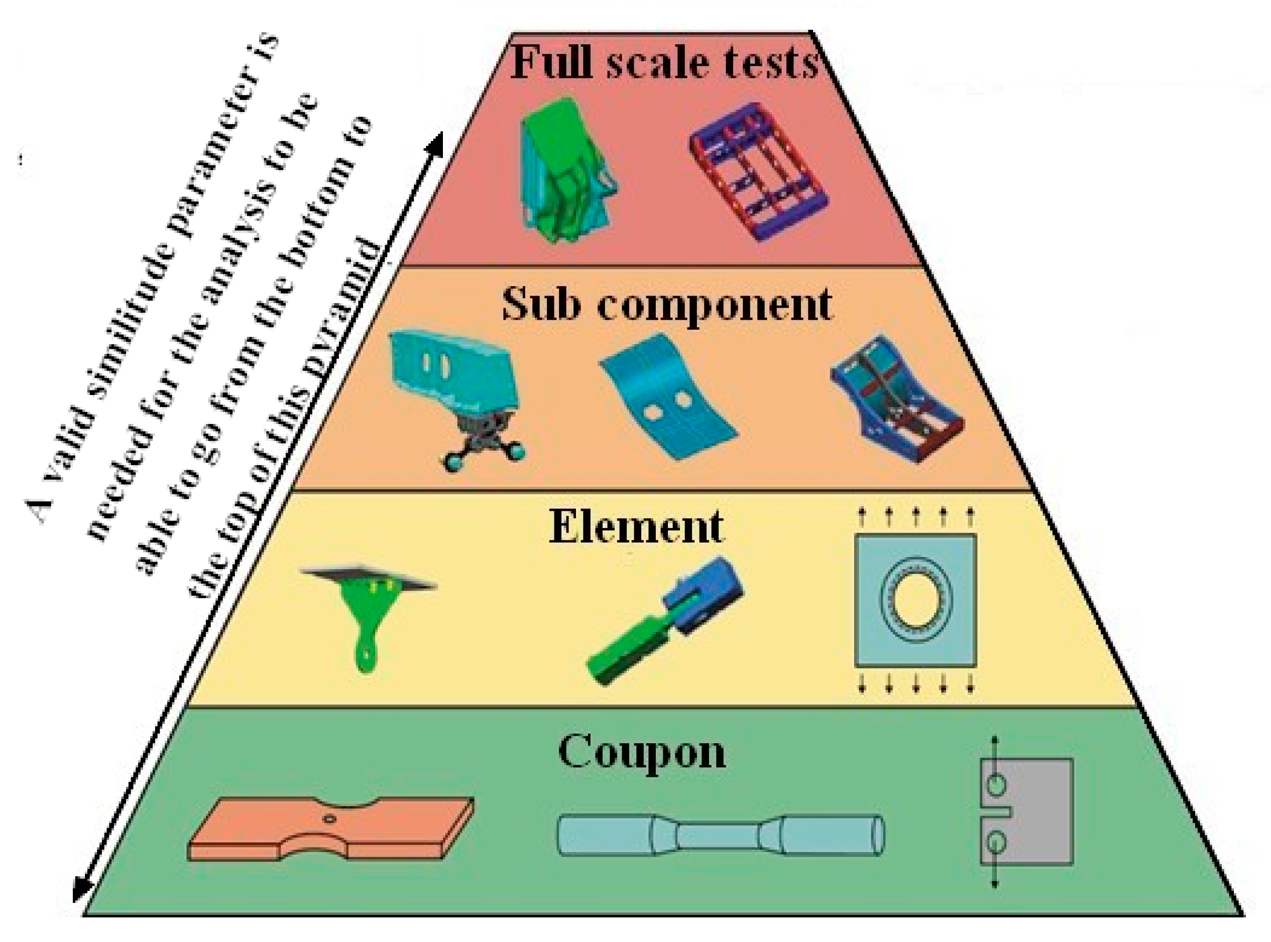
Figure 1. Testing pyramid required for the certification of aircraft structures.
Aerospace 10 00946 g001
Figure 2. Clarification of similitude via an example of cracking in an F/A-18 Y488 bulkhead.
Aerospace 10 00946 g002
Figure 3. A failed Mirage III boron-fibre/epoxy fatigue test specimen.
Aerospace 10 00946 g003
Figure 4. The F/A-18 wing-root step-lap joint specimen.
Aerospace 10 00946 g004
Figure 5. Schematic representation of a small, sub-mm, crack that emanates from one side of a small hole in a large plate subjected to arbitrary remote biaxial stresses.
Aerospace 10 00946 g005
Figure 6. The computed crack growth histories for the biaxial and uniaxial load cases.
Aerospace 10 00946 g006
Figure 7. Schematic of the right-hand side of the symmetrical double over-lap adhesively-bonded specimen discussed in [39,48].
Aerospace 10 00946 g007
Figure 8. The computed (from the present study) and measured [39] crack growth histories.
Aerospace 10 00946 g008
Figure 9. Plan view of the specimen which is a plate with adhesively bonded doublers showing the location of the edge cracks (disbonds) in the adhesive bonds. (The lower and upper doublers bonded to the “inner” AA2024-T3 plate both contain identical disbonds at each of their corners.).
Aerospace 10 00946 g009
Figure 10. Cross-section showing a quarter of the specimen, which is a plate with adhesively bonded doublers, see Figure 9.
Aerospace 10 00946 g010
Figure 11. Mesh details and the definition of crack tip locations A and B for the specimen which is a plate with the adhesively bonded doublers, as shown in Figure 9 and Figure 10.
Aerospace 10 00946 g011aAerospace 10 00946 g011b
Figure 12. The crack length versus cycles histories at the two ends of the crack for the plate with the adhesively bonded doublers shown in Figure 9 and Figure 10 for the various constant amplitude load spectra.
Aerospace 10 00946 g012
Figure 13. The crack length versus cycles histories at the two ends of the crack for the plate with the adhesively bonded doublers shown in Figure 9 and Figure 10 for a FALSTAFF flight load spectrum.
Aerospace 10 00946 g013
Table 1. Values of the Hartman-Schijve constants used for the ‘FM73’ adhesive, from [39].
D (m/cycle)pA′ (J/m2) G t h r (√(J/m2))
1.9 × 10−102.720007.1
Table 2. The Young’s modulus, E, and Poisson’s ratio, υ, of AA2024-T3, and the adhesive FM73, from [39,48].
AA2024-T3FM73
Young’s modulus, E, in MPa72,0002295
Poisson’s ratio, υ0.330.35
Disclaimer/Publisher’s Note: The statements, opinions and data contained in all publications are solely those of the individual author(s) and contributor(s) and not of MDPI and/or the editor(s). MDPI and/or the editor(s) disclaim responsibility for any injury to people or property resulting from any ideas, methods, instructions or products referred to in the content.