Abstract
The objective of this study is to investigate the effects of a magnetic field gradient on the performance of a magnetically shielded Hall thruster. The Particle-in-cell with Monte Carlo collision method (PIC-MCC) is used to simulate the discharge process of the thruster. The performance and plasma characteristics are obtained in conditions with different magnetic field gradients by numerical simulations. As the maximum of the gradient is increased from 1.2 to 3.33 T/m, the electron number density near the channel exit decreases, which leads to less ionization and a weaker radial electric field. As a result, the thrust and specific impulse are decreased, while the plume divergence angle is reduced.
1. Introduction
The Hall thruster is a type of efficient electric propulsion device employed to satellites to complete orbit transfer and station keeping maneuvers.The Hall thruster was first developed in the Soviet Union in the 1960s. Due to its high specific impulse, large thrust to power ratio and high reliability, the Hall thruster has become the most frequently used electric thruster in orbit. In recent years, Hall thrusters have been applied to the orbit maneuver missions for satellites and the main propulsion missions for space probes [1,2]. In a Hall thruster, as shown in Figure 1, electrons are confined by a magnetic field to produce ionization. The ions are accelerated by the electric field between the anode and the cathode and generate thrust. The magnetic field not only determines the propellant ionization process, but is related to the electric field distribution and ion acceleration, which is closely linked with the thruster performance. Hall thrusters have been developed for decades; however, the technology of magnetic field design is still a focus of research due to difficulties involving the complicated mechanisms of the coupling between the magnetic field, electric field and plasma characteristics [3,4].
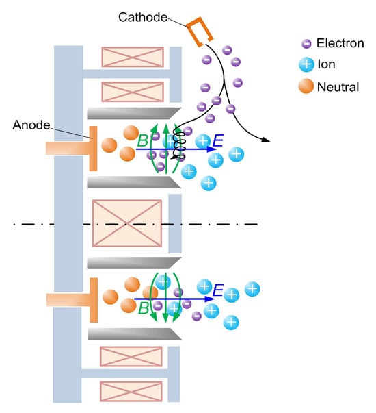
Figure 1.
Schematic diagram of a Hall thruster.
Magnetic shielding, which achieves nearly zero-erosion on the ceramic walls and extends the thruster lifetime [5,6,7], is an important development in Hall thrusters contributing to magnetic field optimization. According to the principle of equipotential state of the magnetic field lines, the magnetic field topology is modified and the ions flux and energy to the wall decrease significantly. The magnetic field in the magnetically shielded (MS) Hall thruster has several differences compared with the traditional Hall thruster. Firstly, unlike the magnetic field lines that intersect the channel walls of traditional Hall thrusters, the magnetic field lines are parallel to the chamfered wall near the exit [7]. Secondly, the peak magnetic flux density is mostly located at the exit plane of traditional Hall thrusters, while its counterpart in MS Hall thrusters is pushed downstream and out of the discharge channel. Thirdly, the magnetic field parameters such as the axial gradient of the radial magnetic field and the curvature of the magnetic field lines all experience changes, either in quantity or in location. As a result, the mechanisms of the magnetic field parameters on the discharge processes need to be investigated for better design of high-performance thrusters considering the MS configuration. The magnetic field gradient involves magnetic flux density distribution and electron transport, which have impacts on thruster performance. Therefore, the magnetic field gradient is one of the most important design parameters.
Efforts have been made to investigate the effects of magnetic field gradients on the thruster discharge characteristics of traditional Hall thrusters [8]. The positive gradient of the magnetic field in the discharge channel can achieve both a low discharge current and low oscillation amplitude [9], and this became one of the criteria in Hall thruster design. One numerical study indicated that a longer zone of intensive magnetic field contributes to a larger electric potential drop and produces minor impacts on the plume divergence [10]. In different magnetic field gradient cases, the variation in thrust, specific impulse and efficiency could not be distinguished. In addition, the magnetic flux density near the anode was not kept constant in the cases in reference [10]. A scalar function of magnetic field gradient was defined and the location of its maximal value was found to be related to the sputtering boundary and ionization zone [11]. The notable influence of the magnetic field gradient on ion acceleration behavior and plasma oscillation have been illustrated by experimental study [12]. The ion energy distributions tended to be more concentrated when the magnetic field gradient was increased. The influences of magnetic field parameters as single variables on thruster performance have been evaluated in the Hall thruster PPS-FLEX [13]. The divergence half-angle decreased slightly from 36.7 to 35.6 deg when the steep gradient of the magnetic field inside the channel was applied, while the thrust performance did not change with a steeper gradient.
The research mentioned above indicates the influence of magnetic field topology on plasma characteristics and thruster performance in traditional Hall thrusters. Due to the changes in configurations and physical mechanisms in plasma in the MS Hall thruster, numerous investigations into the principles and design of the magnetic field have been conducted [14,15]. Compared with the traditional unshielded Hall thruster, the physical processes and performances in MS Hall thrusters were found to be modified. It was demonstrated that the ionization region was located near the channel exit [16] and that the acceleration region was moved downstream of the exit plane [17]. As a result, the performances were found to be lower in a MS Hall thruster than in an unshielded one [18]. The matching characteristics of the magnetic field and the chamfered wall were studied in [15]. In that work, different magnetic field lines were chosen, and the corresponding matched channel walls were manufactured and tested. The tests revealed that the matching characteristics could influence both the thruster performance and wall energy loss [15,19], which provides a reference for magnetic field design.
Investigations on magnetic field parameters are necessary to improve the performances of the MS Hall thruster due to its complicated mechanisms related to plasma. In this paper, the effects of the magnetic field on the performance and plasma characteristics are studied.
2. Computational Methods
2.1. PIC-MCC Method
A two-dimensional axisymmetric model is established for the simulation of the discharge processes in a 1.35 kW MS Hall thruster developed at the Beijing Institute of Control Engineering (BICE). The thruster operates at 360 V/3.75 A with xenon as the propellant. The Particle-in-cell with Monte Carlo collision method (PIC-MCC) is used to simulate the movements and collisions of particles during the discharge. This methodology can capture the motions of particles in the electric and magnetic field at a microscopic level and has been applied to simulate the physical processes in Hall thrusters [20,21]. The features of the electric field, energy distribution, and thruster performances can be obtained in such a simulation [22,23,24].
The computational domain includes the discharge channel and the near plume area. In the computational domain shown in Figure 2, there are five types of boundaries, including the ceramic boundary, magnetic pole boundary (metal wall), anode boundary, symmetric boundary and free space boundary. The ceramic material used in the walls is boron nitride. The cathode is located outside of the thruster and it is also outside of the computational domain; therefore, the cathode electrons are commonly injected at the upper and right free space boundaries, where the electric potential is set as 0 V. There are chamfers at the inner and outer ceramic walls near the exit of the discharge channel, which is a feature of MS Hall thrusters. The magnetic field lines are curved to match the chamfered channel walls. The solution of the collisions between the particles and walls follows the method in reference [20]. The self-consistent electric field is obtained by the Poisson equation, which is solved by the dynamic alternating direction implicit (DADI) algorithm. This algorithm turns a large matrix into a tridiagonal matrix problem [25]. The self-induced magnetic field is negligible compared with the applied one, so the magnetostatic field is pre-computed. Particles including electrons, single charged ions and atoms are all regarded as particles. Ionization, excitation and elastic collisions are considered between the electrons and xenon atoms. Multiple ionizations are not considered in this simulation due to the relatively low collision frequency. Bohm collision is also applied to the simulation to perform the anomalous transport in the Hall thruster [26,27]. The anomalous transport coefficients are determined empirically by comparing the simulation with experimental results and are kept the same in the cases simulated in this paper. According to the criteria presented in Appendix A, the spatial and time parameters of the numerical model are listed in Table 1.
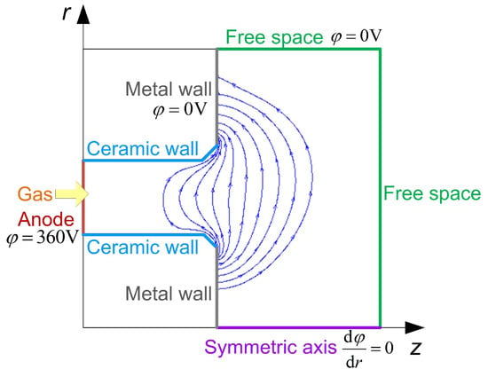
Figure 2.
Schematic diagram of the geometry, computational domain and boundary settings of the 1.35 kW MS Hall thruster.

Table 1.
Simulation parameters.
Due to the enormous computational cost of the PIC-MCC simulation, acceleration methods are applied in the simulation. The significant difference between the mass of electrons and heavy particles (i.e., ions and atoms) leads to a large gap in their velocity. As a result, the heavy particles move much slower than electrons, with the result that a long time is required for the heavy particles to achieve a relatively steady state. Reducing the mass of heavy particles could speed up the convergence of the simulation. The computational time step should be shorter than ωpe−1 and ωce−1, where ωpe is the plasma oscillation frequency and ωce is the electron cyclotron frequency. ωpe is inversely proportional to the square root of electrical permittivity of the vacuum ε0. Increasing ε0 allows a larger time step and accelerates the simulation. Therefore, the acceleration methods and the corresponding recovery of physical solution given by Szabo [20] are applied in this simulation. The mass of heavy particles is reduced by 100 times, and the free space permittivity constant is increased by a factor of 1600 to reduce the grid density. The heavy particles are sped up by a factor of 10 and ωpe−1 increases by a factor of 40 [20,28].
2.2. Magnetic Field Configuration and Model Validation
In order to study the effects of the magnetic field gradient on the discharge and thruster performance, magnetic fields in the thruster are constructed with different axial gradients, keeping constant the peak value and position of the radial magnetic flux density on the discharge channel centerline. The magnetic field near the anode is also kept constant to maintain single variable of the magnetic field conditions in the research. According to the magnetic fields generated by Mazouffre [13], it is possible to change the magnetic field gradient in a magnetic circuit by adjusting the current in several coils. Since generating magnetic fields with different gradients is feasible and has been successfully applied in previous studies [10,13], the method of obtaining the magnetic fields by coils is not within the scope of this article. Instead of designing the magnetic circuit with multiple coils and modifying the coils’ current, in this work, different cases of magnetic field parameters are constructed in a simpler way, which consists of multiplying a baseline field profile (Case 3 in Figure 3) by a piecewise function. The details of the function are demonstrated in Appendix A. As shown in Figure 3, five cases of magnetic field gradients are studied with both a constant magnetic field peak value and a similar morphology of magnetic field lines. The axial position of z = 0 denotes the discharge channel exit, while the negative and positive axial positions are in the channel and plume area, respectively. The radial magnetic flux density keeps increasing axially from the near anode area and reaches its maximum downstream of the channel exit. The maximum magnetic field gradient in Hall thrusters is generally around 1.0–2.6 T/m [4,29,30,31,32]. Taking this range as a reference, the 1.35 kW MS experimental prototype, of which the maximum of magnetic field gradient is 1.52 T/m, is set as the baseline Case 3. The maximum axial gradients of the radial magnetic flux density ranging from 1.2 to 3.33 T/m are listed in Table 2. A wider range of magnetic field gradients, compared with the research performed by Ding [30], has been selected to obtain more obvious results and plasma behaviors at higher gradients.
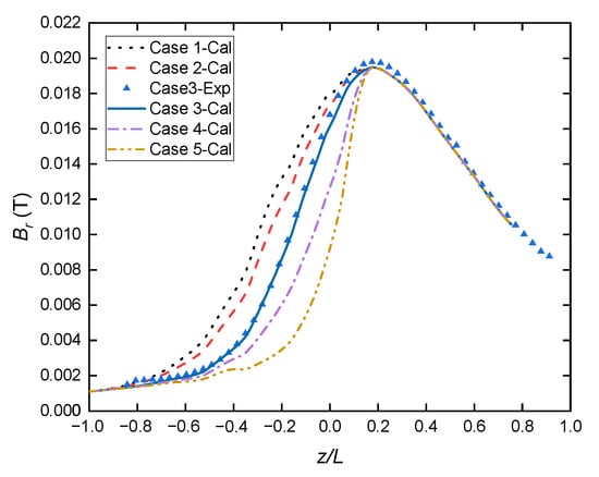
Figure 3.
Axial distribution of the radial magnetic flux density at the channel centerline. (L is the length of the discharge channel.)

Table 2.
The maximum axial gradients of Br in the five cases.
The simulation model is validated by comparing the calculated performance parameters with experimental results as shown in Table 3 and Figure 3. The thruster operated at the following conditions: Ud = 360 V, Id = 3.75 A, and mass flow rate = 4.6 mg/s. The background pressure in the vacuum chamber was maintained at 3 × 10⁻³ Pa with the thruster operating. The thrust T was measured by an electromagnetic feedback balance, and the anode specific impulse Isp-an and the anode efficiency ηan were obtained from the thrust [33]. Since the thrust of the prototype thruster is relatively low, the thrust measurement has an error of 2%. The balance was calibrated in situ by weights before and after the experiment to reduce the error. The magnetic field in Case 3 was measured by a Gauss meter with an error of 0.1%. In order to measure the magnetic field at different positions, the Gauss meter was installed on a displacement platform with a position error of 0.1 mm, which is quite small compared with the thruster dimensions. The Gauss meter was moved at a step of 1 mm from the plume area into the channel on the channel centerline, and the three-dimensional magnetic field was acquired. The magnetic field was measured eight times and the results were averaged to reduce the error. It was shown that the simulation results, including the magnetic field and the thruster performances, were in good accordance with experimental results.

Table 3.
Performance parameters of the 1.35 kW Hall thruster.
3. Results and Discussion
Since the maximum radial magnetic flux density, which is located at the channel exit in a traditional Hall thruster, is pushed downstream of the channel exit plane in the MS Hall thruster, the processes of electron transport and ion acceleration are both altered. The electrons are captured in the region of the intensive magnetic field, where the resistivity is large. As a result, the electric potential mainly drops and the ions primarily accelerate in this region. Compared with the traditional Hall thruster, the acceleration region of the MS Hall thruster is moved downstream and the corresponding physical processes, which are largely dependent on the magnetic field topologies, might present different regularity. Therefore, the trends in performance parameters as they vary with the magnetic field configuration are of interest in thruster optimization.
3.1. Simulation of the Hall Thruster and Performance Results
A series of numerical simulations on the Hall thruster discharge processes are demonstrated for the five cases of magnetic field conditions. The major performance parameters, which are the main concern of this research, are obtained from the simulation. The divergence half-angle is an important performance parameter which links the ions behavior with the macroscopic beam phenomena. The large divergence angle of a Hall thruster may cause deposition on the satellite or its optical elements, leading to the functional failure of the satellite.
The divergence half-angle α is calculated by integrating the ion current density radially from the thruster centerline. As is shown in Figure 4, the boundary of α is defined as the position where 95% of the total ion current is collected. The specific calculation of α is as follows [34]:
where Ii(p = 95%) is 95% of the total ion current, j(r) is the ion current density as a function of radial position r, rout is the radius of the outer ceramic channel, and z1 is the axial distance from the channel exit in the plume area. The thrust T can be calculated by the collected flux and the mean velocity of ions at the right boundary in the simulation:
where , and are the total mass flow rate, ion beam flow rate, and neutral flow rate, respectively, and , and are the mean exit velocity of both kinds of particles, ions and neutrals, respectively [20]. The anode specific impulse Isp,an is defined by [33]
where is the propellant mass flow rate in the anode.
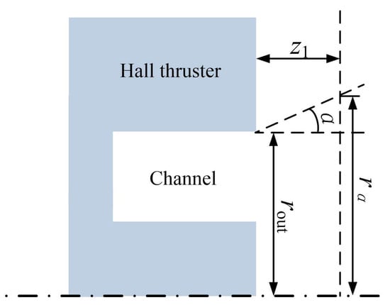
Figure 4.
Schematic diagram of the plume divergence and related parameters.
The variations in the performance parameters with the radial magnetic field gradient are shown in Figure 5. For the magnetic field gradient range studied in this work, it can be seen in Figure 5a that the divergence half-angle α tends to decrease with the increase in the Br gradient. Although the differences in divergence in the five cases are slight, with the minimum and maximum being 32.4 deg and 37.0 deg, respectively, the trend observed could still provide evidence for better beam-focusing characteristics with higher Br gradients. The thrust and anode specific impulse clearly fall with the increase in the Br gradient. The mechanisms which lead to the better focusing and poor thrust performances at high gradients could be investigated by analyzing more detailed plasma discharge characteristics.

Figure 5.
Variation in performance parameters with magnetic field gradients: (a) divergence half-angle; (b) thrust; and (c) anode specific impulse.
3.2. Plasma Properties and Mechanism Analysis
The simulations were run according to the methods described in Section 2 and the plasma properties obtained, including the plasma density and velocity distributions, self-consistent electric field, ion energy distribution function (IEDF) and so on. On this basis, the influences of the B gradient on plasma properties are discussed.
A direct influence of the magnetic field gradient on the plasma is observed for the grad-B drift. The electron drift velocity in the magnetic field with the gradient ∇B is [35]
where u⊥ is the velocity perpendicular to the magnetic force lines, and rL is the Larmor radius, which is calculated as
In the Hall thruster, due to the magnetic field B and its gradient ∇B being both mainly in the r-z plane, the direction of u∇B is azimuthal. Although the numerical model is in two-dimensional coordinates, the three-dimensional velocity and the Lorentz force in the azimuthal direction are considered. Therefore, the azimuthal velocity of electrons could be depicted. On the channel centerline, B is almost radial, so ∇zBr is denoted as ∇B in the following discussion.
It should be mentioned that rL,i is much larger than rL,e and the channel dimensions in the discharge channel of a Hall thruster. Therefore, the electrons are confined by the magnetic field while the ions are often considered as unmagnetized. The ions are predominantly driven by the electric field instead of the magnetic field. As a result, the u∇B considered in the research is only the drift velocity of electrons. The azimuthal component of the electron velocity ue,θ in the Hall thruster model is shown in Figure 6a. The velocity ue,θ increases axially in the channel and reaches its peak at the exit of the channel. The peak values of ue,θ along the centerline vary significantly with ∇B, from around 1 × 10⁶ m/s in Case 1 to more than 4 × 10⁶ m/s in Case 5. To present the variation in ue,θ with ∇B more intuitively, the average azimuthal electron velocity on the channel centerline is introduced and calculated by summing up ue,θ on the grids along the channel centerline, and then divided by the grid numbers. As is shown in Figure 6b, e,θ surges when ∇B increases from 1.2 to 2.11 T/m, and it increases gradually when ∇B increases from 2.11 to 3.33 T/m. The higher value of ue,θ contributes to a higher total electron velocity ue, which is related to the electron-neutral collision frequency υen:
where Qne is the cross section for collisions between electrons and neutrals, and nn is the number density of the neutrals. Among the five cases, the neutral number density distributions are similar, and the cross sections do not vary much. When the electron velocity ue is raised by a higher ∇B, the electron-neutral collision frequency increases and then the scattering enhances the electron transport towards the anode.
υen ≈ nnueQne,
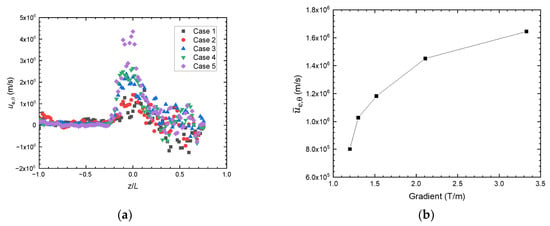
Figure 6.
The electron azimuthal velocity in the five cases: (a) the ue,θ distribution along the channel centerline; (b) the average values of ue,θ on the channel centerline and variation with the B gradient.
Another influence of the magnetic field gradient on the plasma is the effective magnetic confinement of electrons. Because Br peaks outside the discharge channel, for the cases with large ∇B, Br decreases drastically from the peak to a position inside the channel, and as a consequence, the magnetic field may not be strong enough to confine the concentration of electrons. To evaluate the degrees of magnetic confinement of electrons in the axial direction, the Larmor radius of electrons rL according to Equation (6) is computed. As shown in Figure 7, rL become larger when ∇B increases. In Case 5, which has the largest parameter of ∇B in this research, rL reaches its maximum of 0.0054 m near the channel exit. A large rL commonly implies poor confinement of electrons due to a large distance of axial movement in the cyclotron. Moreover, the high velocity of electrons in the channel near the exit also contributes to the large rL as ∇B is raised further.
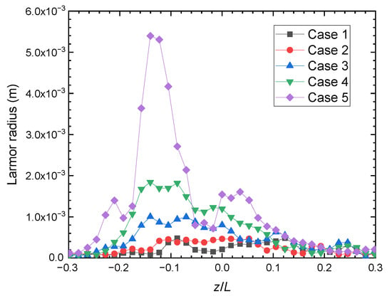
Figure 7.
Axial distribution of electron Larmor radius along the channel centerline.
As a result of the changes in the electron transport process, the plasma distribution and relevant physical processes are affected. The above descriptions of ∇B and electron transport can be further examined through the electron distribution results. Referring to Figure 8, with ∇B increasing from Case 1 to Case 5, the concentration of electrons moves upstream in the channel. In the MS Hall thruster, further increasing the ∇B parameter would make it more difficult to confine the electrons and to maintain the peak electron density near the channel exit.
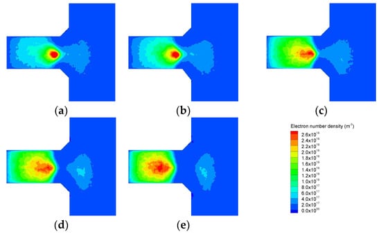
Figure 8.
Contours of the electron number density distribution: (a) Case 1; (b) Case 2; (c) Case 3; (d) Case 4; and (e) Case 5.
As is discussed above, the enhanced electron transport resulting from higher ∇B leads to lower electron density in the channel, especially near the exit. The axial electron number density ne distribution is shown in Figure 9. The maximum value of ne on the channel centerline decreases, from the channel exit towards the anode, from higher than 3 × 10¹⁸ to 2 × 10¹⁸ m−3 when ∇B increases from 1.2 to 3.33 T/m. Since electrons are the source of the ionization process, less ionization occurs at low electron densities. As a result, fewer ions are generated in the channel and the related performance parameters, such as thrust and specific impulse, are reduced, which is presented in Section 3.1.
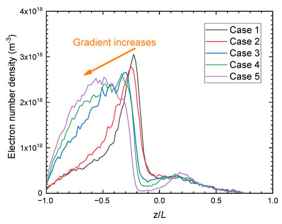
Figure 9.
The axial distribution of electron number density on the channel centerline.
As for the mechanisms of the effects of ∇B on plume divergence, it might be related to the radial characteristics of the plasma. It can be seen in Figure 8 that the electron density becomes lower near the channel exit when ∇B increases. Accordingly, the net charge density ρnet changes along with electron density, according to the Poisson equation:
The gradient of the radial electric field Er is proportional to the net charge density ρnet. The radial distributions of ρnet are shown in Figure 10 for two values of z/L inside the channel. In the cases with lower ∇B, the net charge density tends to be larger. This tendency is more significant at z/L = −0.14 than at z/L = −0.07 because the density of plasma is higher deep in the channel. Overall, as shown in Figure 11, the radial electric field increases as ∇B decreases. The difference in Er between Case 1 and Case 5 reaches 1600 V/m at z/L = 0.17, which generates a gap in the radial velocity between the cases.
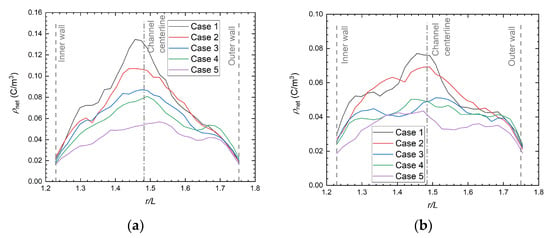
Figure 10.
Radial distribution of the net charge density at (a) z/L= −0.14; (b) z/L= −0.07.
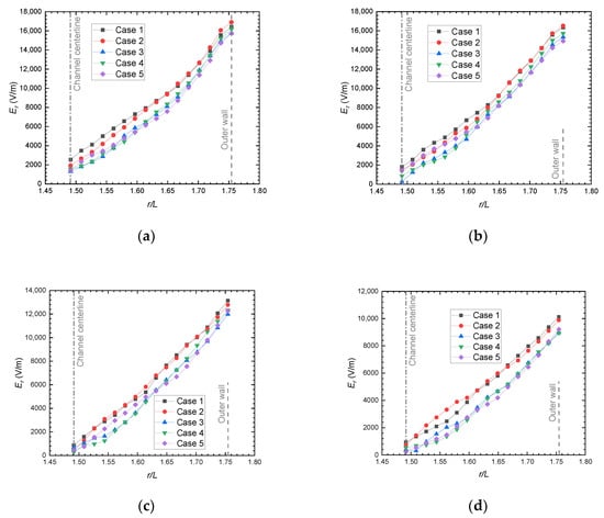
Figure 11.
Radial distribution of Er at axial positions: (a) z/L = −0.07, (b) z/L = 0, (c) z/L = 0.10, and (d) z/L = 0.17.
The radial acceleration of ions in the plume is analyzed by the radial IEDF. An area away from the channel centerline is selected to collect the ions in the diverging plume. This area ranges axially from z/L = 0.23 to 0.75, which is out of the channel, and it ranges radially from the outer channel wall to r/L= 2.5. Ions are collected and the radial ion energy distribution functions in the five cases are shown in Figure 12. The radial IEDF presents double peaks in all of the five cases. The high energy peaks appear from 77 to 120 eV, while the low energy peaks are in the range from 16 to 43 eV. There are relatively more low-energy ions than the high-energy ones. When ∇B increases, the energy of the both populations decreases. This effect is attributed to the decrease in the radial electric field with the increase in ∇B, as shown in Figure 11.
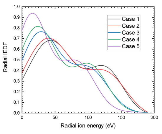
Figure 12.
The radial ion energy distribution function in a diverging plume area.
The multi-peak phenomenon is also demonstrated in experimental research reported in the literature [12,36]. The mechanism is commonly explained by the fact that the low and high energy populations are possibly generated by the backflow of neutral atoms and the main flow of the propellant, respectively. However, whether the multi-peak of radial IEDF has the same mechanism as reported for the total IEDF needs to be further explored. The ions in the diverging plume area, as mentioned above, are traced back to their initially ionized positions. As shown in Figure 13, the two populations present distinct ionization regions in Case 1. For the population of low radial energy ions, the ions are generated mainly near the centerline in the channel, and a small portion of the ions are generated in the diverging plume, where a relatively weak electric field and only a short distance are available for ions to accelerate. In contrast, for the population of high radial energy ions, the ions are generated near the channel wall. As the electric field lines show in Figure 14, the ions generated near the wall are moved further off the channel centerline and accelerated radially to the diverging plume by the electric field.
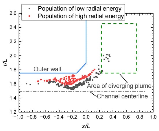
Figure 13.
The initial positions where the ions in the diverging plume are first generated, including the low energy and high energy populations in Case 1.
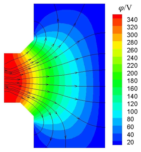
Figure 14.
The plasma potential contour overlaid with electric field lines in Case 1.
4. Conclusions
Magnetic shielding in the Hall thruster eliminates the channel wall erosion by matching the magnetic field lines with the chamfered channel walls, which can increase the thruster lifetime. Achieving better performance should be the next goal of MS Hall thruster research. Compared with traditional Hall thrusters, MS Hall thrusters have different magnetic field topology features, among which, the region of positive magnetic field gradient is extended to downstream of the channel exit. This parameter is related to physical processes such as electron transport and ion acceleration, which influence the performance of a Hall thruster. Clarifying the effects of the magnetic field gradient on the MS Hall thruster performance and its mechanisms is necessary for further optimization of these thrusters. In this paper, the PIC-MCC method is used to simulate the discharge process of a 1.35 kW MS Hall thruster to explore the effects of the magnetic field gradient on thruster performance and plasma characteristics.
When the maximum of magnetic field gradient ∇B on the channel centerline ranges from 1.2 to 3.33 in the 1.35 kW MS Hall thruster, there are two mechanisms by which the electron distribution is affected. On the one hand, the higher ∇B enhances grad-B drift and increases electron azimuthal velocity, which contributes to a higher frequency of electron-neutral collision, and as a consequence, it increases the ionization rate and intensifies the electron transport. The concentration of electrons moves upstream in the channel and the electron density near the exit decreases with increasing ∇B. On the other hand, when ∇B is raised, the area of strong magnetic field shrinks and the magnetic field at the exit cannot provide sufficient confinement to the concentration of electrons, which also leads to lower electron density near the exit. In the axial direction, the lower electron density in cases with larger ∇B brings less ionization, resulting in fewer accelerated ions and lower thrust and specific impulse. In the radial direction, the net charge density decreases with the reduced electron density, leading to a weaker radial electric field and smaller divergence angle. The results obtained here provide a reference for the parametric design of the magnetic field in MS Hall thrusters.
Author Contributions
Conceptualization, Q.L. and Y.L.; Data curation, Q.L.; Formal analysis, Y.H.; Funding acquisition, Y.H.; Investigation, Q.L.; Methodology, Q.L.; Project administration, Y.L.; Resources, Y.L. and W.M.; Software, Q.L. and Y.H.; Supervision, Y.L.; Validation, W.M.; Visualization, W.M.; Writing—original draft, Q.L.; Writing—review and editing, Y.L., Y.H. and W.M. All authors have read and agreed to the published version of the manuscript.
Funding
This research was funded by National Defense Basic Research Project Funding (JCKY2021603B033).
Data Availability Statement
The supporting data will be provided upon request to the corresponding author.
Conflicts of Interest
The authors declare no conflict of interest.
Appendix A
This appendix includes details about the simulation model.
The computational time step should be shorter than ωpe−1 and ωce−1, where ωpe is the plasma oscillation frequency and ωce is the electron cyclotron frequency:
The orthogonal grids are built and their sizes are uniform. The grid size should be shorter than the Debye length:
The piecewise function f, which is used to generate the magnetic field cases with different axial gradient, is:
where a1, a2, b2, c2, a3, b3, and c3 are the coefficients of the function, and z1, z2 and z3 are the axial positions. z3 is located at the magnetic field peak. Magnetic fields with different axial gradients can be obtained numerically through multiplying the radial component of a baseline field Br by this piecewise function. To keep the curvature of the magnetic field constant, the axial component Bz is also multiplied by the same function f(z).
References
- Frieman, J.D.; Gilland, J.H.; Kamhawi, H.; Mackey, J.; Williams, J.G.J.; Hofer, R.R.; Peterson, P.Y. Wear trends of the 12.5 kw hermes hall thruster. J. Appl. Phys. 2021, 130, 143303. [Google Scholar] [CrossRef]
- Tajmar, M.; Sedmik, R.; Scharlemann, C. Numerical simulation of smart-1 hall-thruster plasma interactions. J. Propuls. Power 2009, 25, 1178–1188. [Google Scholar] [CrossRef]
- Kim, V.P. On the longitudinal distribution of electric field in the acceleration zones of plasma accelerators and thrusters with closed electron drift. Plasma Phys. Rep. 2017, 43, 486–498. [Google Scholar] [CrossRef]
- Wang, L.; Xu, Y.; Ding, Y.; Xu, F.; Bao, L.; Meng, Y.; Li, H.; Wei, L.; Yu, D. Effects of the peak magnetic field location on discharge performance of a 100-W hall thruster with large gradient magnetic field. Vacuum 2022, 199, 110965. [Google Scholar] [CrossRef]
- Mikellides, I.G.; Katz, I.; Hofer, R.R.; Goebel, D.M.; de Grys, K.; Mathers, A. Magnetic shielding of the channel walls in a hall plasma accelerator. Phys. Plasmas 2011, 18, 033501. [Google Scholar] [CrossRef]
- Mikellides, I.G.; Katz, I.; Hofer, R.R.; Goebel, D.M. Magnetic shielding of a laboratory hall thruster. I. Theory and validation. J. Appl. Phys. 2014, 115, 043303. [Google Scholar] [CrossRef]
- de Grys, K.; Mathers, A.; Welander, B.; Khayms, V. Demonstration of 10,400 hours of operation on 4.5 kw qualification model hall thruster. In Proceedings of the 46th AIAA/ASME/SAE/ASEE Joint Propulsion Conference & Exhibit, Nashville, TN, USA, 25 July 2010. pp. AIAA 2010-6698. [Google Scholar] [CrossRef]
- Li, H.; Fan, H.; Liu, X.; Ding, M.; Ding, Y.; Wei, L.; Yu, D.; Wang, X. Effect of magnetic field configuration on discharge characteristic of a hall effect thruster with a variable channel. Vacuum 2019, 162, 78–84. [Google Scholar] [CrossRef]
- Morozov, A.I.; Esipchuk, Y.V.; Kapulkin, A.M.; Nevrovskii, V.A.; Smirnov, V.A. Effect of the magnetic field on a closed-electron-drift accelerator. Sov. Phys. Tech. Phys. 1972, 17, 612–619. [Google Scholar]
- Garrigues, L.; Hagelaar, G.J.M.; Bareilles, J.; Boniface, C.; Boeuf, J.P. Model study of the influence of the magnetic field configuration on the performance and lifetime of a hall thruster. Phys. Plasmas 2003, 10, 4886–4892. [Google Scholar] [CrossRef]
- Gorshkov, O.A.; Shagayda, A.A.; Irishkov, S.V. The influence of the magnetic field topology on hall thruster performance. In Proceedings of the 42nd AIAA/ASME/SAE/ASEE Joint Propulsion Conference & Exhibit, Sacramento, CA, USA, 9 July 2006. pp. AIAA 2006-4472. [Google Scholar] [CrossRef]
- E, P.; Duan, P.; Jiang, B.-H.; Liu, H.; Wei, L.-Q.; Xu, D.-G. On the effect of magnetic field gradient on the discharge characteristics of hall thrusters. Acta Phys. Sin. Ed. 2010, 59, 7182–7190. [Google Scholar] [CrossRef]
- Mazouffre, S.; Bourgeois, G.; Vaudolon, J.; Garrigues, L.; Hénaux, C.; Harribey, D.; Vilamot, R.; Rossi, A.; Zurbach, S.; Le Méhauté, D. Development and testing of hall thruster with flexible magnetic field configuration. J. Propuls. Power 2015, 31, 1167–1174. [Google Scholar] [CrossRef]
- Ma, D.; Zeng, D.; Wang, L.; Ding, Y.; Wei, L.; Li, H.; Yu, D. Numerical simulation study on the influence of channel geometry on discharge characteristics of low-power magnetically shielded hall thrusters. Vacuum 2020, 180, 109547. [Google Scholar] [CrossRef]
- Wang, Z.; Li, H.; Zhong, C.; Hu, Y.; Ding, Y.; Wei, L.; Yu, D. Matching characteristics of magnetic field configuration and chamfered channel wall in a magnetically shielded hall thruster. Plasma Sci. Technol. 2021, 23, 104008. [Google Scholar] [CrossRef]
- Garrigues, L.; Santhosh, S.; Grimaud, L.; Mazouffre, S. Operation of a low-power hall thruster: Comparison between magnetically unshielded and shielded configuration. Plasma Sources Sci. Technol. 2019, 28, 034003. [Google Scholar] [CrossRef]
- Grimaud, L.; Mazouffre, S. Ion behavior in low-power magnetically shielded and unshielded hall thrusters. Plasma Sources Sci. Technol. 2017, 26, 055020. [Google Scholar] [CrossRef]
- Grimaud, L.; Mazouffre, S. Performance comparison between standard and magnetically shielded 200 w hall thrusters with BN-SiO2 and graphite channel walls. Vacuum 2018, 155, 514–523. [Google Scholar] [CrossRef]
- Wang, Z.; Li, H.; Hu, Y.; Zhong, C.; Ding, Y.; Wei, L.; Yu, D. Expanding the design freedom of the chamfered wall shape of a magnetically shielded hall thruster. Vacuum 2023, 207, 111603. [Google Scholar] [CrossRef]
- Szabo, J.J. Fully Kinetic Numerical Modeling of a Plasma Thruster. Ph.D. Thesis, Massachusetts Institute of Technology, Cambridge, MA, USA, 2001. [Google Scholar]
- Taccogna, F.; Longo, S.; Capitelli, M.; Schneider, R. Self-similarity in hall plasma discharges: Applications to particle models. Phys. Plasmas 2005, 12, 053502. [Google Scholar] [CrossRef]
- Liu, H.; Wu, B.; Yu, D.; Cao, Y.; Duan, P. Particle-in-cell simulation of a hall thruster. J. Phys. D Appl. Phys. 2010, 43, 165202. [Google Scholar] [CrossRef]
- Cho, S.; Watanabe, H.; Kubota, K.; Funaki, I. The effects of cathode boundary condition on particle simulation of a spt-100-like hall thruster. In Proceedings of the 52nd AIAA/SAE/ASEE Joint Propulsion Conference, Salt Lake City, UT, USA, 25–27 July 2016. [Google Scholar] [CrossRef]
- Wei, L.; Gao, Q.; Li, W.; Li, H.; Ding, Y.; Lv, Y.; Wu, F.; Gu, W.; Yu, D. Simulation of plasma dynamics during discharge ignition in hall thruster. Eur. Phys. J. D 2019, 73, 55. [Google Scholar] [CrossRef]
- Mahalingam, S. Particle Based Plasma Simulation for an Ion Engine Discharge Chamber. Ph.D. Thesis, Wright State University, Dayton, OH, USA, 2007. [Google Scholar]
- Mikellides, I.G.; Ortega, A.L. Challenges in the development and verification of first-principles models in hall-effect thruster simulations that are based on anomalous resistivity and generalized ohm’s law. Plasma Sources Sci. Technol. 2019, 28, 014003. [Google Scholar] [CrossRef]
- Lafleur, T.; Baalrud, S.D.; Chabert, P. Theory for the anomalous electron transport in hall effect thrusters. II. Kinetic model. Phys. Plasmas 2016, 23, 053503. [Google Scholar] [CrossRef]
- Cao, X.; Liu, H.; Yu, D. Simulation of discharge process of hall thruster under the internal and external cathode conditions. Eur. Phys. J. Appl. Phys. 2020, 90, 10801. [Google Scholar] [CrossRef]
- Ding, Y.; Wei, L.; Jia, D.; Yu, D. Relationship between magnetic field strength and discharge voltage of aton-type hall thrusters. Phys. Scr. 2014, 89, 085602. [Google Scholar] [CrossRef]
- Ding, Y.; Li, P.; Zhang, X.; Wei, L.; Sun, H.; Peng, W.; Yu, D. Effects of the magnetic field gradient on the wall power deposition of hall thrusters. J. Plasma Phys. 2017, 83, 905830205. [Google Scholar] [CrossRef]
- Haas, J.; Gulczinski, I.F.; Gallimore, A.; Spanjers, G.; Spores, R. Performance characteristics of a 5 kw laboratory hall thruster. In Proceedings of the 34th AIAA/ASME/SAE/ASEE Joint Propulsion Conference and Exhibit, Cleveland, OH, USA, 13 July 1998. pp. AIAA 1998-3503. [Google Scholar] [CrossRef]
- Ding, Y.; Peng, W.; Wei, L.; Sun, G.; Li, H.; Yu, D. Computer simulations of hall thrusters without wall losses designed using two permanent magnetic rings. J. Phys. D Appl. Phys. 2016, 49, 465001. [Google Scholar] [CrossRef]
- Hopping, E.P.; Huang, W.; Xu, K.G. Small hall effect thruster with 3d printed discharge channel: Design and thrust measurements. Aerospace 2021, 8, 227. [Google Scholar] [CrossRef]
- Zhang, Z.; Zhang, Z.; Xu, S.; Ling, W.Y.L.; Ren, J.; Tang, H. Three-dimensional measurement of a stationary plasma plume with a Faraday probe array. Aerosp. Sci. Technol. 2021, 110, 106480. [Google Scholar] [CrossRef]
- Chen, F.F. Introduction to Plasma Physics; Springer Science & Business Media: Berlin/Heidelberg, Germany, 2016; pp. 18–19. [Google Scholar]
- Beal, B.E.; Gallimore, A.D. Energy analysis of a hall thruster cluster. In Proceedings of the 28th International Electric Propulsion Conference, Toulouse, France, 17–21 March 2003. [Google Scholar]
Disclaimer/Publisher’s Note: The statements, opinions and data contained in all publications are solely those of the individual author(s) and contributor(s) and not of MDPI and/or the editor(s). MDPI and/or the editor(s) disclaim responsibility for any injury to people or property resulting from any ideas, methods, instructions or products referred to in the content. |
© 2023 by the authors. Licensee MDPI, Basel, Switzerland. This article is an open access article distributed under the terms and conditions of the Creative Commons Attribution (CC BY) license (https://creativecommons.org/licenses/by/4.0/).