Article

UGV Path Optimization in UAV-Assisted Environments Using Visibility-Aware Path Simplification

1
Department of Electronic and Telecommunication Engineering, University of Moratuwa, Moratuwa 10400, Sri Lanka
2
School of Engineering & Digital Technologies, University of Southern Queensland, Springfield Central, QLD 4300, Australia
3
School of Engineering and Technology, University of New South Wales, Canberra, ACT 2612, Australia
*
Authors to whom correspondence should be addressed.
J. Sens. Actuator Netw. 2026, 15(3), 41; https://doi.org/10.3390/jsan15030041
Submission received: 10 April 2026 / Revised: 18 May 2026 / Accepted: 19 May 2026 / Published: 22 May 2026

Abstract

This study proposes a modular path optimization framework for uncrewed ground vehicles (UGVs) in uncrewed aerial vehicle (UAV)-assisted navigation environments to improve the efficiency, smoothness, and executability of paths generated by classical grid-based path planning algorithms. The principal innovation of this work is the Visibility and Line-of-Sight Path Simplification (VLoSPS) algorithm, an algorithm-independent post-processing method that removes redundant waypoints through long-range axis-aligned visibility analysis while preserving path feasibility. VLoSPS is integrated with the Direction-Aware Path Planning Approach (DAPPA) to reduce angular deviations and improve directional continuity. The proposed framework is applicable to standard algorithms, including A*, Dijkstra, Breadth-First Search (BFS), and Depth-First Search (DFS), without modifying their internal search mechanisms. The main academic contributions comprise the formulation of a generalized post-processing architecture for UAV-derived occupancy maps, the introduction of a visibility-aware waypoint reduction strategy, and extensive validation using two synthetic maze datasets and three UAV-derived semantically segmented real-world datasets. On the Göttingen Maze Dataset, the VLoSPS and DAPPA pipeline reduced the average path lengths of A*, Dijkstra, BFS, and DFS by 5.42%, 9.46%, 10.44%, and 86.00%, respectively. The consistent improvements across real-world datasets demonstrate the effectiveness, computational feasibility, and general applicability of the proposed framework for UAV-assisted UGV path planning. The implementation code and benchmark resources developed in this study are publicly released to promote reproducibility and facilitate future research.

1. Introduction

Path planning is a fundamental problem in robotics and autonomous navigation, involving the systematic determination of an optimal and feasible trajectory for an agent to move from a start point to a goal within a defined environment [1]. It plays a critical role in diverse applications such as mobile robotics, autonomous vehicles, warehouse automation, search and rescue, and UAV-assisted navigation [2,3,4,5]. As autonomous systems grow in complexity, particularly in multi-agent and UAV-UGV collaborative scenarios (Figure 1), the demand for optimal path planning strategies becomes increasingly significant [6,7,8]. The path planning pipeline begins by converting real-world environment images into grid-based maps, in which the operational space is represented as discrete cells classified as either free or obstructed based on existing environmental features. These grid maps provide a structured and computationally tractable representation of the environment, facilitating systematic path planning. Effective path planning in such environments directly contributes to operational efficiency, energy-aware navigation, and overall mission success. Recent vehicle routing studies further indicate that practical factors, including vehicle-specific dynamics, energy consumption behavior, operational constraints, and adaptive decision-making, are important for improving path optimization in real-world autonomous systems [9,10].
Graph-based algorithms such as BFS, DFS, Dijkstra’s algorithm, and A* remain widely adopted for path planning due to their predictable behavior and ease of implementation [11]. These algorithms construct search graphs over discrete occupancy grids and evaluate paths based on cumulative costs and heuristics. Among these, A* is often selected for its heuristic-driven efficiency, while Dijkstra guarantees optimal paths purely based on distance metrics [12]. However, the discretized structure of grid-based planning inherently produces piecewise-linear paths aligned to the grid, which often contain sharp turns, unnatural motion patterns, and redundant waypoints that reduce trajectory smoothness and efficiency [13]. These artifacts reduce trajectory smoothness and execution efficiency, limiting the suitability of grid-based paths for real-world deployment. Although advanced sampling-based methods, such as Rapidly exploring Random Trees (RRT) and Probabilistic Roadmaps (PRM), are effective in continuous and high-dimensional spaces, they generally exhibit higher computational overhead and still require subsequent refinement to produce smooth and executable paths [8].
To address these limitations, this study proposes a modular and extensible path planning optimization framework that extends these algorithms with a two-stage post-processing architecture. The proposed pipeline begins by constructing a binary occupancy map from UAV-captured, semantically segmented imagery. A safety margin is applied through morphological dilation to ensure collision-free paths that respect the physical footprint and localization uncertainties of the robot. The first post-processing stage introduces a Visibility and Line-of-Sight Path Simplification (VLoSPS) algorithm, which reduces redundant waypoints by exploiting long-range visibility between path nodes. The second stage, termed the Direction-Aware Path Planning Approach (DAPPA), further refines the path by minimizing angular deviations and enforcing smooth directional continuity. In combination, these techniques refine the initially irregular and grid-constrained paths into shorter, smoother, and more executable trajectories while preserving feasibility. Furthermore, the proposed approach is algorithm-independent and modular, enabling improvements to paths produced by any standard path planning algorithm without altering their fundamental search mechanisms.
The main contributions of this study can be summarized as follows:
  • A comprehensive performance evaluation of classical path planning algorithms is conducted using a large-scale benchmark maze dataset, providing an assessment of their efficiency, scalability, and limitations in grid-based environments.
  • A novel algorithm-independent post-processing technique, VLoSPS, is developed and integrated with DAPPA to improve the smoothness and geometric quality of generated trajectories.
  • An experimental analysis is presented to demonstrate improvements in path optimality and structural coherence, validating the effectiveness of the proposed method against baseline algorithms and existing approaches.
  • A synthetic benchmark dataset consisting of 6000 binary maze images across four grid resolutions, 10 × 10, 30 × 30, 50 × 50, and 100 × 100, is released to support reproducible experimentation and future path planning research.
  • Semantic-to-binary converted versions of three UAV-derived real-world imagery datasets are released to facilitate systematic evaluation of path planning methods in realistic urban and aerial–ground collaborative scenarios.
The remainder of this manuscript is organized as follows. Section 2 reviews related work in the domain of path planning algorithms and post-processing techniques. Section 3 describes the overall system architecture, including grid construction and occupancy mapping. Section 4 details the preparation of both synthetic and real-world benchmark datasets used for evaluation. Section 5 outlines the proposed path optimization methodology, including the VLoSPS and DAPPA algorithms. Section 6 presents the experimental evaluation and results, highlighting improvements achieved on both synthetic and real-world datasets. Finally, Section 7 concludes and discusses potential directions for future work.

2. Related Work

Classical search-based algorithms such as Breadth-First Search (BFS) and Depth-First Search (DFS) have been widely adopted in mobile robotics for their systematic and exhaustive exploration capabilities [14,15,16]. Several studies have explored improvements to BFS to improve its efficiency in structured environments. For example, ref. [17] integrated BFS within a local frontier-based exploration framework, improving mapping accuracy but incurring higher computational cost as the environment size increased. Similarly, ref. [18] combined BFS with a greedy optimization strategy to reduce energy consumption, minimize turns, and limit sensor activations in grid-based navigation tasks. BFS has also been applied in AI-driven maze navigation [19], demonstrating its reliability in structured pathfinding problems. However, its computational and memory requirements increase considerably with maze complexity, and its performance becomes less favorable in larger environments where path quality and efficiency are important [15]. A comparative study [20] showed that although DFS uses less memory than BFS, it often produces longer and less optimal paths. To address some of these limitations, ref. [21] introduced Recursive Backtracking DFS, which incorporates self-learning to improve return-path selection in unknown environments, such as search-and-rescue scenarios.
Heuristic-based algorithms such as A* and Dijkstra have also seen significant enhancements that improve the efficiency and optimality of path planning in practical applications [22]. A geometric A* (Geom. A*) proposed in [13] for AGVs in port environments replaced sharp turns with cubic B-splines, producing smoother and more efficient paths. A hybrid method in [23] improved A* through the integration of artificial potential fields and a dynamic cost function that penalizes turns near obstacles, improving path smoothness and trajectory stability. In [24], an improved A* combined unknown path cost estimation and local map zooming with an enhanced LQR controller for path tracking, leading to lower tracking errors and improved overall path execution. Similarly, ref. [25] developed an improved A* for UAVs by refining the evaluation and node-selection strategies and incorporating a Mixed-Integer Linear Programming formulation, improving flight-path optimality and computational efficiency. Several studies have also extended Dijkstra’s algorithm to improve path quality in surface and aerial navigation. In [26], an extended Dijkstra algorithm used Delaunay triangulation and a two-dimensional transformation to optimize paths across uneven terrain in both single- and multi-robot systems. A recent study [27] applied Dijkstra-based navigation in both 2D and 3D spaces through obstacle modeling and battery-aware constraints to improve navigation efficiency. Additionally, ref. [28] improved Dijkstra through an eight-angle search strategy, reducing unnecessary turns and improving path smoothness in warehouse environments.
Parent Node-Weighted A* (PNW A*) [29] improves the node evaluation process by incorporating parent-node heuristic information with a tunable weighting factor, which supports more consistent movement toward the target and reduces unnecessary zig-zag expansions. Region Weighted A* (RegW A*) [30] applies region-dependent heuristic weighting by partitioning the grid along the start-to-goal direction and adjusting the heuristic metric across regions. Further path improvement is achieved through collinearity-based simplification, line-of-sight waypoint removal, and corner smoothing via arc- or tangent-based generation. Density-Aware A* (Dens A*) [31] integrates obstacle density into the search guidance term, modifies successor expansion to avoid corner crossing near obstacles, and applies bidirectional smoothing with a safety margin to improve path quality. Theta* [32] extends A* for any-angle path planning on grid maps by allowing a successor node to connect directly to the parent of the current node when a clear line of sight is available, thereby reducing grid-induced angularity and generating more direct paths with fewer unnecessary turns.
Recent research on UGV navigation has increasingly moved toward perception-aware, sensor-fusion-driven, and dynamically adaptive navigation frameworks. Reliable UGV navigation requires consistent estimation of vehicle pose, obstacle geometry, terrain structure, and traversable regions under uncertain field conditions. LiDAR point clouds, RGB or depth images, inertial measurements, wheel odometry, GPS signals, and local elevation information are commonly fused to improve localization accuracy and environmental perception [33]. Such fusion is usually performed through probabilistic filtering, feature-level fusion, occupancy-grid updating, semantic mapping, or learning-based representation extraction. Camera-LiDAR fusion and bird’s-eye-view (BEV) representations have also gained increasing attention because they transform heterogeneous spatial observations into a unified top-down representation for free-space estimation, obstacle detection, and motion planning in complex navigation scenes [34]. These advances are especially relevant to UAV-assisted UGV navigation, where UAV-derived maps provide global situational awareness while onboard UGV sensors provide local feedback required for safe execution.
Obstacle avoidance and path optimization in complex dynamic environments represent another important direction in recent UGV research. Recent studies have extended artificial potential field methods, Dynamic Window Approach (DWA), reinforcement learning, and hybrid planning strategies to address moving obstacles, narrow passages, uncertain maps, and real-time replanning requirements [35,36,37,38,39]. Improved A* variants normally modify the cost function, heuristic term, or node expansion strategy to reduce unnecessary turns and avoid obstacle-dense regions. In contrast, artificial potential field methods introduce attractive and repulsive forces to guide motion in locally constrained environments [35]. DWA-based methods operate in the velocity space of the robot and evaluate candidate velocity commands according to heading, clearance, and dynamic feasibility, making them suitable for local obstacle avoidance and short-horizon motion control [37]. Vision-based approaches further support obstacle recognition and traversability estimation by extracting semantic and geometric cues from onboard images [36]. Multi-robot and formation-based UGV navigation extend these methods through inter-robot distance constraints, cooperative collision avoidance, and distributed decision-making, which are important in constrained and obstacle-rich environments [40,41].
In parallel, sampling-based methods, especially Rapidly Exploring Random Trees (RRT), have also been improved by focusing on path optimization and post-processing in complex environments [8]. For instance, ref. [42] proposed an improved RRT for industrial robots that utilizes a regression mechanism and adaptive expansion to reduce redundant exploration and improve path efficiency. A hybrid approach combining RRT*-Smart with A* was presented in [43], using beacon-guided and fast sampling strategies along with A* for narrow-passage navigation, resulting in improved convergence and optimality. Similarly, ref. [44] integrated RRT* with Particle Swarm Optimization to improve trajectory smoothness and reduce overall path length relative to conventional methods. Spline-based RRT was proposed in [45] to generate curvature-continuous paths for non-holonomic robots, while ref. [46] introduced a variable-step RRT* for quadrotors in obstacle-dense environments, improving efficiency through target-biased sampling and adaptive step sizes. Despite these advancements, RRT-based approaches remain susceptible to randomness, which can result in suboptimal trajectories or difficulty in obtaining feasible paths in highly constrained or high-resolution environments.
Another important frontier is 3D spatial modeling and terrain-aware path planning. Conventional 2D occupancy-grid planning simplifies the environment into traversable and non-traversable regions, but this abstraction does not fully represent elevation changes, slope, roughness, overhanging structures, ground irregularities, or terrain-dependent traversal cost. Recent studies have explored 3D point-cloud maps, voxel grids, digital elevation models, traversability maps, and learning-based 3D planners for UGV operation in outdoor and unstructured environments [47,48,49]. Improved DDQN-based 3D planning methods formulate navigation as a sequential decision-making problem in which the robot learns actions based on spatial state representations and reward functions related to distance, safety, and goal convergence [47]. Terrain-aware approaches combine slope cost, surface roughness, clearance, and obstacle density into the planning objective, allowing the planner to select paths that are not only short but also physically executable by the UGV. These studies indicate that future UGV navigation systems require closer integration of global map guidance, local obstacle perception, 3D terrain representation, and adaptive path refinement.
Open-source frameworks and path optimization methods play an important role in contemporary motion planning. OMPL offers standardized implementations and interfaces for sampling-based planners and supports integration with ROS-based systems for benchmarking and practical deployment [50]. Path refinement methods further improve an initial solution by increasing clearance and improving smoothness through techniques such as shortcutting and clearance-based heuristics [51]. Extensions of OMPL, such as cHyRRT and cHySST, have expanded this capability to hybrid dynamical systems while providing probabilistic completeness and asymptotically near-optimal performance [52]. In addition, TrajOpt improves paths via sequential convex optimization with collision checking, producing collision-free, dynamically feasible motion [53].
Although these approaches demonstrate significant gains in path planning performance, many are developed for specific algorithmic frameworks, sensing configurations, or environment assumptions. As a result, their applicability and benefits are often limited to particular navigation scenarios and cannot be easily generalized across different grid-based planning methods. In this context, the proposed VLoSPS and DAPPA framework contributes a planner-independent post-processing approach that improves the smoothness and geometric consistency of paths generated from UAV-derived occupancy maps while preserving compatibility with multiple baseline algorithms.

3. System Overview

In this section, we outline the overall pipeline architecture of the proposed method and detail the process of grid construction and occupancy mapping.

3.1. Overall Pipeline Architecture

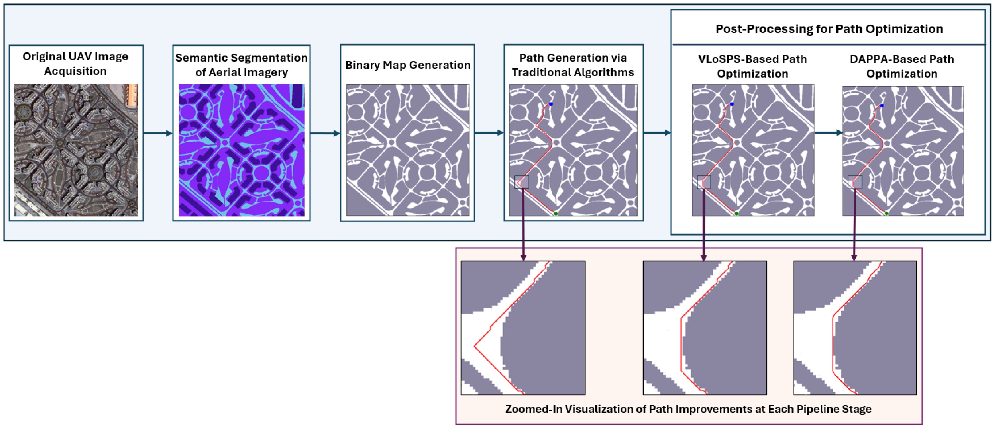
The proposed path planning optimization pipeline for ground-based mobile robots comprises multiple sequential stages aimed at improving navigation performance in complex environments using UAV-captured imagery, as illustrated in Figure 2. The process begins with the acquisition of raw aerial images, which are then processed through a semantic segmentation stage. During this stage, machine learning techniques classify each pixel into semantically meaningful categories, such as navigable terrain, obstacles, and structural features, thereby providing a detailed, high-level understanding of the operational environment.
The semantically segmented image is then converted into a binary occupancy map, in which traversable and non-traversable regions are represented using a simplified grid format. This abstraction facilitates more computationally efficient path planning while retaining essential environmental details. Using this binary occupancy map as input, an initial path is generated with classical path-planning algorithms such as A*, Dijkstra, or BFS. Although these algorithms generate feasible paths, the resulting trajectories often exhibit suboptimal characteristics, including sharp transitions, excessive length, and unnatural movement patterns due to the discretized, grid-based nature of the planning space. To overcome these limitations, the pipeline integrates a two-stage post-processing framework designed to enhance the efficiency and smoothness of the initial path. Specifically, the initial path is refined sequentially, first by applying the VLoSPS algorithm to optimize visibility-based waypoint reduction, then by DAPPA, which further improves the path through geometric and directional consistency analysis. A series of zoomed-in visualizations for each stage of the pipeline is presented at the bottom of Figure 2, illustrating incremental improvements in path quality.

3.2. Grid Construction and Occupancy Mapping

A grid-based representation can be constructed for any bounded, continuous environment, regardless of its geometric complexity, by discretizing the space into a two-dimensional uniform grid G with r rows and c columns. This discretization provides a computationally tractable abstraction in which each cell g i , j G corresponds to a distinct, finite region of the environment. Each cell is uniquely identified by its row index i { 0 , 1 , , r 1 } and column index j { 0 , 1 , , c 1 } . The resolution of the grid, determined by the size of each cell, can be adjusted to balance computational efficiency and the level of environmental detail captured. This flexibility allows any continuous environment to be systematically modeled in a structured and uniform manner, facilitating efficient path planning.
All planning and navigation operations are performed entirely within this discrete grid space, thereby avoiding the complexities of working directly in continuous coordinates. The occupancy status of each cell is described by the binary occupancy function in Equation (1).
O ( i , j ) = 1 , if the cell at ( i , j ) is free ( traversable ) 0 , if the cell at ( i , j ) is occupied ( obstacle )
where O : G { 0 , 1 } .
Initially, obstacles in the environment are encoded by assigning O ( i , j ) = 0 to the corresponding cells in G. However, to ensure robust, collision-free navigation, it is necessary to include a safety margin around obstacles. This margin accounts for the physical footprint of the robot as well as possible localization errors, effectively producing an inflated representation of the occupied regions and resulting in a more conservative and safe configuration space. This is achieved by applying a morphological dilation [54,55] to the set of occupied cells defined in Equation (2).
O = { ( i , j ) G O ( i , j ) = 0 } .
The dilated set of occupied cells O , shown in Equation (3), incorporates the safety margin, where B ρ ( i , j ) denotes a neighborhood of radius ρ (either square or circular) centered at ( i , j ) , with  ρ selected according to the physical dimensions of the robot and the desired clearance. The updated occupancy grid O after dilation is defined in Equation (4).
O = ( i , j ) O B ρ ( i , j ) ,
O ( i , j ) = 0 , if ( i , j ) O 1 , otherwise .
This dilation process inflates the occupied regions of the grid, ensuring that any planned path maintains sufficient clearance from obstacles and reducing the risk of collisions. The resulting inflated occupancy grid O provides a reliable and conservative representation of the environment for subsequent path planning.

4. Benchmark Dataset Preparation for Path Planning Evaluation

In this section, we present a brief overview of the three semantically segmented real-world datasets used to evaluate the proposed algorithms, along with a new synthetic maze dataset prepared to facilitate benchmarking in controlled environments.

4.1. Semantic Dataset Preparation for Urban Path Planning

This study utilizes three publicly available, high-resolution datasets to support road extraction and subsequent path planning in complex urban environments. Each dataset offers a distinct combination of perspective, geographic scope, and imaging modality, ranging from satellite and airborne to UAV-based imagery. This diversity provides a comprehensive evaluation of the proposed navigation framework across varied urban contexts. A semantic-to-binary transformation is applied by retaining only the road class and excluding all other semantic categories by generating binary road masks that reduce background complexity and focus computational resources on identifying unobstructed, navigable regions. The characteristics and relevance of the three benchmark datasets used in this study are detailed below.

4.1.1. MBRSC Dubai Aerial Dataset

This dataset [56] was released as part of a joint open-access initiative between Humans in the Loop and the Mohammed Bin Rashid Space Centre (MBRSC), UAE. It comprises high-resolution satellite imagery of Dubai, with pixel-level semantic segmentation across six classes: buildings, unpaved land, roads, vegetation, water, and unlabeled areas. The dataset includes 72 images organized into six larger tiles, capturing diverse urban infrastructure, including arterial roadways, residential developments, and mixed-use areas. The road class is annotated using consistent labeling conventions, enabling the generation of accurate binary road masks. Owing to its satellite perspective and large-scale spatial coverage, this dataset is particularly suitable for evaluating global path planning strategies in structured urban settings with clearly defined, modern road networks.

4.1.2. ISPRS Urban Semantic Dataset

This dataset [57,58] serves as a benchmark in the domain of high-resolution airborne image segmentation, developed by ISPRS Working Group III/4 for the semantic labeling challenge. It comprises true orthophoto tiles of urban regions, including Vaihingen and Potsdam. This dataset is particularly challenging due to high intra-class variability and low inter-class separability among urban elements such as roads, vegetation, and buildings. It includes detailed pixel-level semantic labels, making it well-suited for rigorous evaluation of road extraction methods. Its inclusion enables validation of the proposed approach in environments with intricate urban morphology and complex aerial views.

4.1.3. UAVid Dataset

The UAVid dataset [59] provides a ground-level perspective using high-resolution, oblique-view imagery captured by UAV-mounted 4K cameras. It consists of 300 densely annotated images organized into temporal sequences, with semantic labels across eight categories: roads, buildings, trees, low vegetation, static vehicles, moving vehicles, humans, and background clutter. These street-level scenes are representative of real-world UAV surveillance applications in urban environments. This dataset presents several real-world challenges, including significant scale variation, dynamic object motion, and the need to preserve temporal consistency. These factors are critical for the development and evaluation of real-time aerial–ground collaborative navigation systems.

4.2. Synthetic Maze Dataset Generation for Controlled Path Planning Evaluation

A synthetic maze image dataset was constructed to evaluate the performance of the proposed path post-processing algorithms under controlled conditions. This dataset comprises 6000 binary maze images, evenly distributed across four resolution categories, namely 10 × 10 , 30 × 30 , 50 × 50 , and  100 × 100 grids, with 1500 images per class.
Each maze image represents a binary grid where white pixels denote traversable paths and black pixels denote obstacles. During dataset generation, it was ensured that a valid path exists between a designated source and destination point in every maze instance. This condition was verified using the BFS algorithm, guaranteeing that each sample is solvable and thus suitable for algorithmic evaluation. This dataset provides a scalable and diverse benchmark for assessing the structural quality and efficiency of path simplification and refinement techniques. The complete dataset has been publicly released to support reproducible experimentation and further path planning and optimization research.

5. Path Optimization Methodology

This section presents the proposed path optimization methodology formulated as an algorithm-independent post-processing framework for improving grid-based paths generated in UAV-assisted UGV navigation. The methodology is designed to refine the output of classical graph-based path planning algorithms by reducing redundant waypoint sequences, shortening unnecessary grid-constrained movements, and improving directional consistency. The framework consists of two sequential refinement stages. The first stage introduces the VLoSPS algorithm, which performs long-range axis-aligned visibility analysis to remove redundant intermediate waypoints. The second stage applies DAPPA, which improves the geometric regularity of the simplified path by minimizing angular deviations and reducing inefficient turning behavior.

5.1. Post-Processing Frameworks

Let the path generated by a standard grid-based planning algorithm be represented as an ordered discrete waypoint sequence, as defined in Equation (5).
P = [ p 0 , p 1 , , p n 1 ]
where each waypoint p i = ( r i , c i ) Z 2 corresponds to a grid cell in a binary occupancy map G { 0 , 1 } R × C . The grid value G [ r , c ] = 1 denotes a traversable cell, while G [ r , c ] = 0 denotes an occupied or non-traversable cell. The objective of the proposed post-processing framework is to construct an optimized path, as expressed in Equation (6).
P * = [ q 0 , q 1 , , q m 1 ] , m n
The optimized path must preserve the initial and terminal waypoints of the original path, as specified in Equation (7).
q 0 = p 0 , q m 1 = p n 1
The optimization process is constrained by collision-free feasibility, meaning that each consecutive segment in P * must remain within traversable regions of the occupancy grid.
The geometric length of a discrete path is computed using Equation (8).
L ( P ) = i = 0 n 2 p i + 1 p i 2
In addition to path length, the number of retained waypoints and the accumulated angular deviation affect the practical executability of the trajectory. Therefore, the post-processing objective can be expressed through the composite path cost in Equation (9).
J ( P ) = α L ( P ) + β | P | + γ Θ ( P )
where | P | denotes the number of waypoints, Θ ( P ) denotes the cumulative angular deviation of the path, and  α , β , and  γ are non-negative weighting coefficients. In Equation (9), the first term penalizes excessive path length, the second term penalizes redundant waypoint retention, and the third term penalizes unnecessary directional variation. The proposed VLoSPS and DAPPA stages address these three components through visibility-aware waypoint reduction and direction-aware geometric refinement, respectively.

5.1.1. Visibility and Line-of-Sight Path Simplification

The VLoSPS algorithm is proposed as a visibility-aware waypoint reduction method for simplifying discrete grid-based paths. Its main contribution is the farthest-feasible waypoint selection strategy, in which the algorithm searches for the most distant waypoint that remains directly visible from the current waypoint under axis-aligned line-of-sight constraints. It reduces redundant intermediate waypoints and generates a more compact path, preserving the feasibility of the original path.
For two waypoints p i = ( r i , c i ) and p j = ( r j , c j ) , where j > i , the grid segment connecting them is formalized in Equation (10).
Γ ( p i , p j ) = { ( r i , c ) c [ min ( c i , c j ) , max ( c i , c j ) ] } , r i = r j { ( r , c i ) r [ min ( r i , r j ) , max ( r i , r j ) ] } , c i = c j , otherwise
As shown in Equation (10), a valid candidate segment exists only when the two waypoints are aligned along the same row or column. Based on this segment definition, the axis-aligned visibility function is defined in Equation (11).
V ( p i , p j ; G ) = 1 , Γ ( p i , p j ) and G [ z ] = 1 , z Γ ( p i , p j ) 0 , otherwise
Equation (11) states that two waypoints are mutually visible if they lie on the same row or column and every grid cell along the connecting segment is traversable.
The horizontal visibility condition used in the implementation is obtained from Equation (11) and is given in Equation (12).
G [ r i ] [ c ] = 1 , c [ min ( c i , c j ) , max ( c i , c j ) ]
Similarly, the vertical visibility condition is derived from Equation (11) and is expressed in Equation (13).
G [ r ] [ c i ] = 1 , r [ min ( r i , r j ) , max ( r i , r j ) ]
Equations (12) and (13) confirm that the direct grid-aligned connection between two retained waypoints does not intersect any obstacle cell.
At a given waypoint index i, VLoSPS selects the farthest visible waypoint according to the selection rule in Equation (14).
j * ( i ) = max j { i + 1 , , n 1 } V ( p i , p j ; G ) = 1
After selecting p j * ( i ) , the current index is updated using Equation (15).
i j * ( i )
The process continues until the terminal waypoint p n 1 is reached. The retained waypoint indices are represented using the recursive index sequence in Equation (16).
s 0 = 0 , s l + 1 = j * ( s l ) , s M = n 1
Using the index sequence defined in Equation (16), the final VLoSPS-refined path is constructed as shown in Equation (17).
P VLoSPS = [ p s 0 , p s 1 , , p s M ]
Since every transition in P VLoSPS satisfies the visibility condition in Equation (11), the simplified path preserves collision-free feasibility. In addition, because each retained waypoint is selected using Equation (14), the algorithm removes the maximum number of intermediate waypoints permitted under the local visibility constraint. This produces a compact path representation with fewer redundant grid-constrained segments. The procedural implementation of VLoSPS is presented in Algorithm 1.
As shown in Algorithm 1, the simplified path is generated by repeatedly selecting the farthest waypoint that satisfies the visibility condition defined in Equation (11). The worst-case computational complexity of VLoSPS is governed by the reverse candidate search and repeated visibility checks. For a path containing n waypoints and for a maximum visibility segment length of l max , the worst-case complexity is expressed in Equation (18).
O ( n 2 l max )
Equation (18) indicates that the additional computational cost is introduced by long-range visibility evaluation, while the benefit is stronger waypoint compression.

5.1.2. Direction-Aware Path Planning Approach

DAPPA is applied after VLoSPS to improve the directional structure of the simplified path. Although VLoSPS reduces the number of redundant waypoints, the resulting path can still contain abrupt angular transitions caused by grid-constrained movement. DAPPA addresses this limitation by analyzing local path geometry and applying direction-aware refinement at intermediate waypoints. The detailed formulation of DAPPA was presented in our previous work [60].
Let P = [ p 0 , p 1 , , p n 1 ] denote the path considered for direction-aware refinement. For each intermediate waypoint p i = ( r i , c i ) , where 1 i n 2 , the incoming and outgoing segment vectors are defined in Equations (19) and (20), respectively.
v i = p i p i 1 = ( r i r i 1 , c i c i 1 )
v i + = p i + 1 p i = ( r i + 1 r i , c i + 1 c i )
Using the segment vectors in Equations (19) and (20), the angular deviation at p i is computed as shown in Equation (21).
θ i = cos 1 v i · v i + v i 2 v i + 2 , θ i [ 0 , 180 ]
The cumulative angular variation in the path is then expressed in Equation (22).
Θ ( P ) = i = 1 n 2 θ i
As indicated by Equation (22), a lower cumulative angular value corresponds to improved directional continuity and reduced turning effort.
Algorithm 1 Visibility and Line-of-Sight Path Simplification
Require: 
Path P = [ p 0 , p 1 , , p n 1 ] , Grid G
Ensure: 
Simplified Path P simplified
   1:
if  | P | < 3   then
   2:
   return P
   3:
end if
   4:
Initialize P simplified [ p 0 ]
   5:
i 0
   6:
while  i < | P | 1   do
   7:
     farthest i + 1
   8:
    for  j | P | 1 to i + 1  step  1  do
   9:
        Let p i = ( x i , y i ) P [ i ] , p j = ( x j , y j ) P [ j ]
10:
         visible False
11:
        if  p i = p j  then
12:
             visible True
13:
        else if  x i = x j  then
14:
             y 1 min ( y i , y j ) , y 2 max ( y i , y j )
15:
             visible True
16:
            for  y = y 1 to y 2  do
17:
                if  x i < 0 or x i r or y < 0 or y c or G [ x i ] [ y ] 1  then
18:
                     visible False
19:
                    break
20:
                end if
21:
            end for
22:
        else if  y i = y j  then
23:
             x 1 min ( x i , x j ) , x 2 max ( x i , x j )
24:
             visible True
25:
            for  x = x 1 to x 2  do
26:
                if  x < 0 or x r or y i < 0 or y i c or G [ x ] [ y i ] 1  then
27:
                     visible False
28:
                    break
29:
                end if
30:
            end for
31:
        end if
32:
        if visible then
33:
             farthest j
34:
            break
35:
        end if
36:
    end for
37:
    Append P [ farthest ] to P simplified
38:
     i farthest
39:
end while
40:
return  P simplified
The turning orientation at p i is determined using the signed two-dimensional cross product in Equation (23).
Δ i = ( r i r i 1 ) ( c i + 1 c i ) ( c i c i 1 ) ( r i + 1 r i )
In Equation (23), Δ i > 0 represents a leftward turn, while Δ i < 0 represents a rightward turn. This sign information provides the directional basis for local refinement.
The waypoint refinement decision is defined in Equation (24).
D ( p i ) = remove , θ i = 0 and V ( p i 1 , p i + 1 ; G ) = 1 retain , θ i > 90 adjust , 0 < θ i 90
According to Equation (24), collinear redundant waypoints are removed when direct feasibility is preserved, waypoints required for major directional transitions are retained, and moderate turns are adjusted to improve smoothness.
For the adjustment case, the local traversable neighborhood of p i is defined in Equation (25).
N ( p i ) = { z Z 2 G [ z ] = 1 , z lies within the local search neighborhood of p i }
Using the neighborhood definition in Equation (25), the feasible candidate set is expressed in Equation (26).
C i = { z N ( p i ) V ( p i 1 , z ; G ) = 1 and V ( z , p i + 1 ; G ) = 1 }
Equation (26) states that each candidate point maintains line-of-sight connectivity with the adjacent waypoints. The preferred refinement candidate is then selected by minimizing the local geometric cost in Equation (27).
z i * = arg min z C i λ 1 z p i 1 2 +   p i + 1 z 2 + λ 2 θ i ( z )
In Equation (27), λ 1 and λ 2 control the relative contributions of local path length and angular deviation. The adjusted waypoint is then computed using the refinement coefficient K [ 0 , 1 ] , as defined in Equation (28).
p i new = round ( 1 K ) p i + K z i *
The cases associated with the value of K are summarized in Equation (29).
K = 0 , the original waypoint is retained 1 , the waypoint is fully shifted to the selected refinement candidate ( 0 , 1 ) , the waypoint is partially adjusted
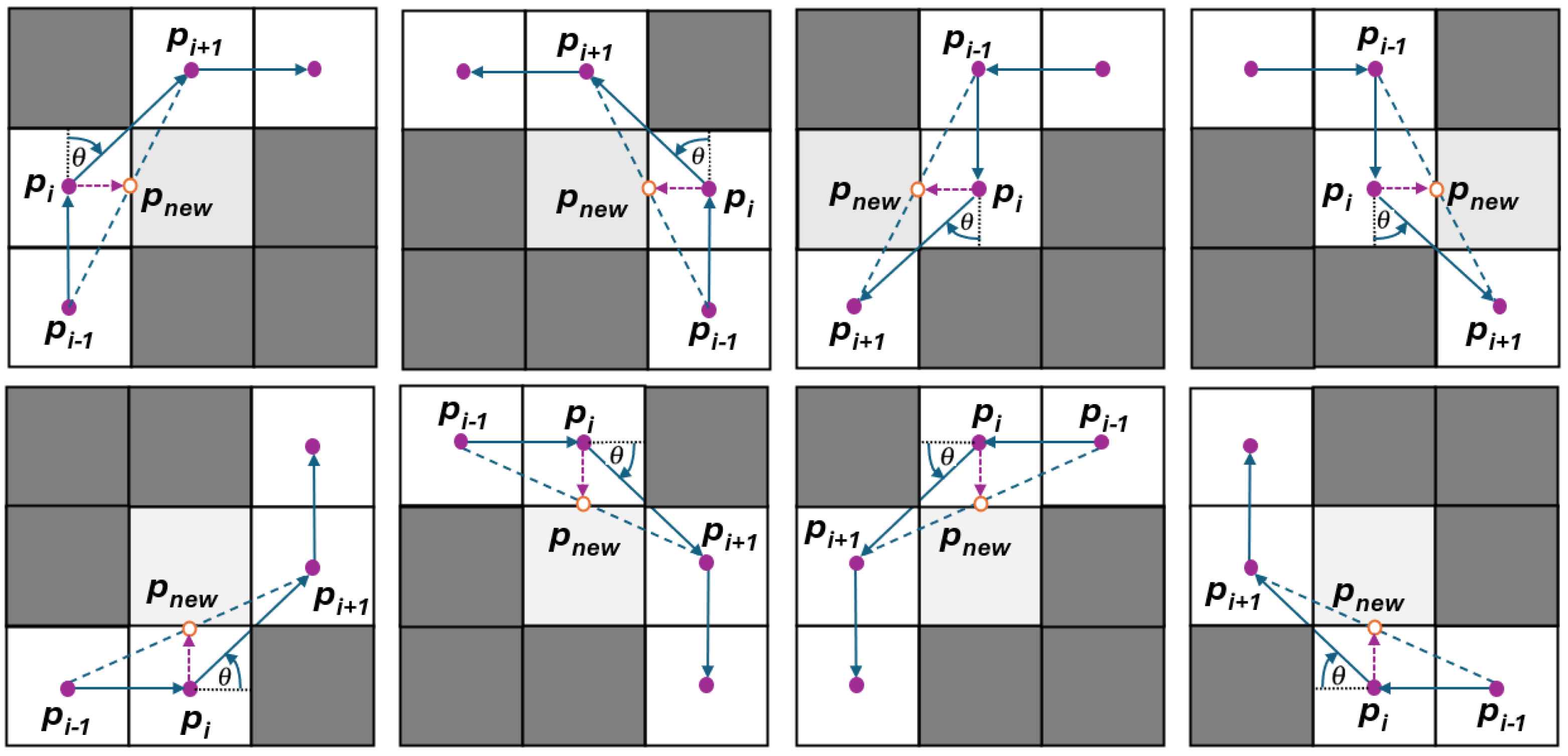
As indicated in Equation (29), K controls the strength of direction-aware waypoint refinement. The local refinement concept of DAPPA is illustrated in Figure 3.
As illustrated in Figure 3, through the repeated application of Equations (19)–(28), DAPPA reduces unnecessary directional changes, maintaining local feasibility. In this formulation, DAPPA is employed as a local path-refinement mechanism to improve the angular continuity of consecutive path segments. The occupancy map is initially inflated according to the ground robot dimensions. Therefore, the path generated before DAPPA refinement already satisfies the required clearance from obstacle boundaries. Accordingly, the subsequent smoothing operation adjusts the local three-point angular configuration, maintaining the collision-free feasibility established by the inflated map representation. The combined path optimization sequence is expressed in Equation (30).
P * = F DAPPA F VLoSPS ( P , G ) , G
In Equation (30), F VLoSPS denotes the visibility-based simplification operator, and F DAPPA denotes the direction-aware refinement operator.

5.2. Comparative Analysis of CLoSPO and VLoSPS Algorithms

Both Constrained Line-of-Sight Path Optimization (CLoSPO) and VLoSPS reduce redundant waypoints through axis-aligned line-of-sight evaluation. However, their search procedures and waypoint selection rules differ significantly. CLoSPO follows an incremental forward search strategy, whereas VLoSPS applies a reverse long-range candidate search to identify the farthest feasible waypoint. This distinction represents a key methodological advancement of VLoSPS, as it shifts the simplification process from locally constrained waypoint selection to farthest-feasible visibility-based waypoint selection.
For the current waypoint p i , CLoSPO advances through the path in the forward direction and selects the last visible point before the first visibility violation. This behavior is formulated in Equation (31).
j CLoSPO ( i ) = max j > i V ( p i , p t ; G ) = 1 , t { i + 1 , , j }
Equation (31) indicates that CLoSPO is controlled by local continuity of visibility along the forward scan. Once a violation is encountered, the search terminates, and the last valid waypoint is retained.
In contrast, VLoSPS evaluates the remaining candidate waypoints in reverse order and selects the farthest candidate that satisfies direct visibility from the current waypoint, as defined in Equation (32).
j VLoSPS ( i ) = max j > i V ( p i , p j ; G ) = 1
Equation (32) prioritizes maximum waypoint compression under the visibility constraint. Therefore, VLoSPS can remove a larger number of intermediate points when long obstacle-free horizontal or vertical segments exist.
The relationship between the two waypoint selection approaches is expressed in Equation (33).
j VLoSPS ( i ) j CLoSPO ( i )
whenever a farther waypoint satisfies direct visibility beyond the locally constrained stopping point of CLoSPO. Equation (33) explains the higher path compactness achieved by VLoSPS in environments with long traversable grid-aligned corridors.
The main methodological differences between CLoSPO and VLoSPS are summarized in Table 1.
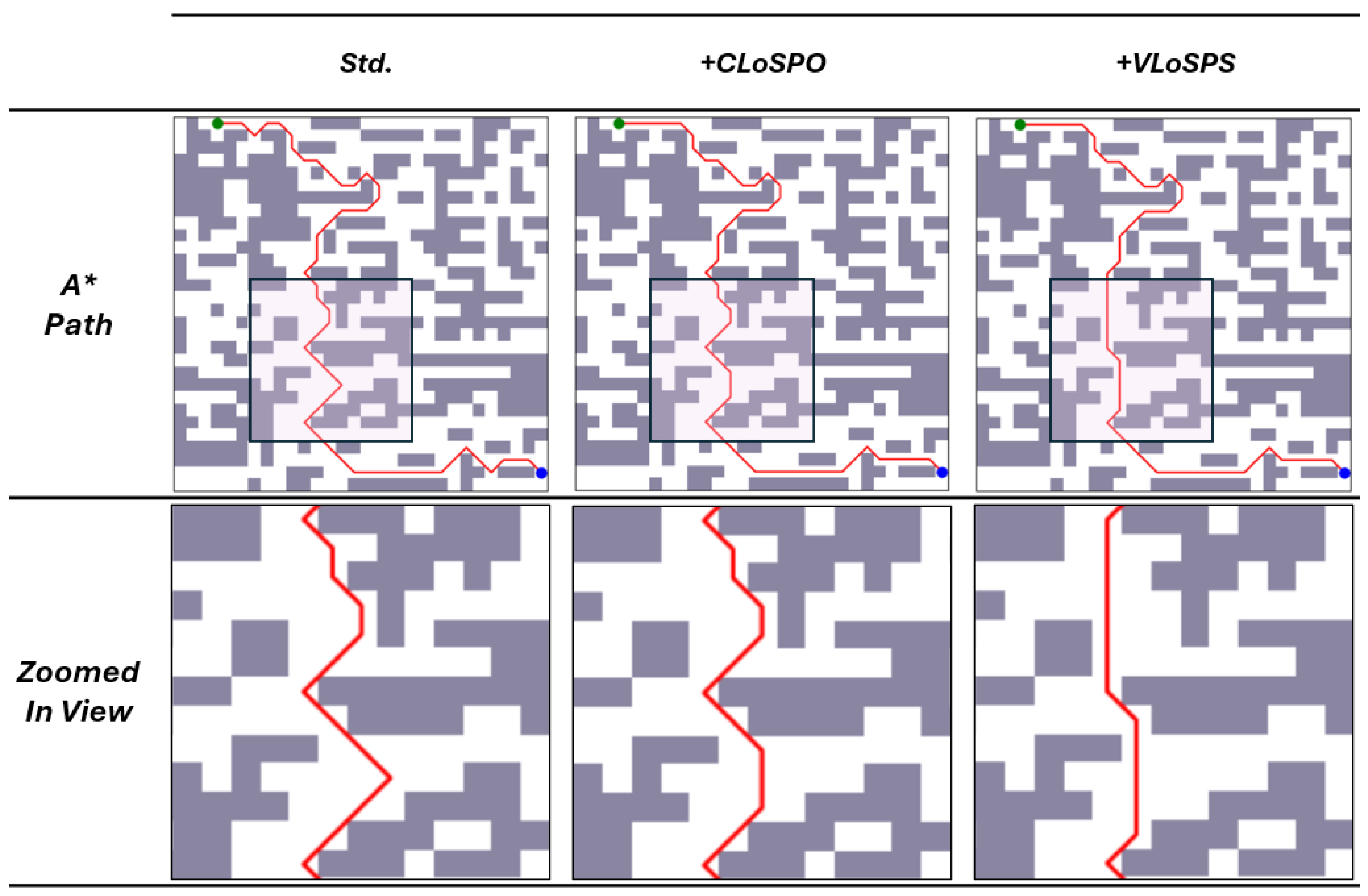
As summarized in Table 1, VLoSPS differs from CLoSPO through its farthest-feasible waypoint selection method and broader candidate evaluation process. A visual comparison of path simplification using CLoSPO and VLoSPS is presented in Figure 4.
The qualitative comparison in Figure 4 is consistent with the analytical comparison presented in Table 1. Therefore, the proposed post-processing framework contributes a mathematically defined and algorithm-independent refinement approach for improving the path length, waypoint structure, and directional quality of classical grid-based path planning outputs.

6. Experimental Evaluation

This section presents the experimental evaluation of the proposed path optimization framework. The evaluation includes visual analyses of UAV-derived map sequences, comparisons of path generation before and after post-processing, and quantitative path length assessments against existing algorithms using benchmark datasets. The proposed framework was implemented and evaluated in a Google Colab-based Python 3.12 environment, with numerical computation and path optimization operations performed using the NumPy library. The experiments were accessed and managed through a local workstation equipped with a 12th Gen Intel(R) Core(TM) i7-1255U processor operating at 1.70 GHz, 16 GB RAM, a 477 GB SSD, and a 64-bit Windows operating system. As the implementation was executed in Google Colab, the computational setup primarily represents the Python-based cloud execution environment used for evaluating the proposed path planning and optimization framework.

6.1. Comparative Visualization of Proposed Post-Processing Techniques Applied to Various Path Planning Algorithms

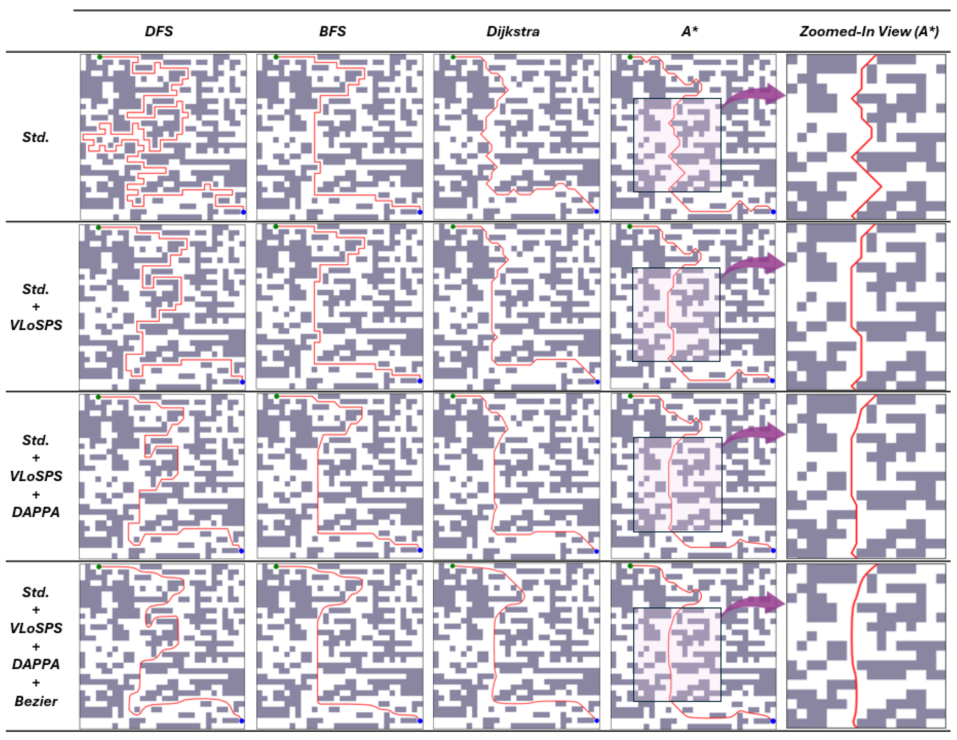
Figure 5 presents a qualitative visual comparison of path planning outcomes generated by four classical algorithms under three different processing stages: standard (Std.), after applying VLoSPS, and after the full VLoSPS+DAPPA pipeline. DFS produces highly convoluted paths with excessive detours and backtracking due to its depth-prioritized nature. It explores each branch as far as possible, often disregarding path optimality, which results in inefficient trajectories. BFS, while producing more direct paths than DFS, tends to produce paths with rigid, axis-aligned patterns, resulting in blocky or stair-like transitions, particularly around corners.
On the other hand, Dijkstra’s algorithm systematically explores the search space based on the lowest cumulative cost from the starting point, resulting in smoother and more optimal paths. However, as it does not incorporate directional guidance toward the goal, its paths may be slightly longer. A* addresses this by integrating a heuristic function to estimate the cost of the goal, allowing the algorithm to focus its exploration more efficiently. As a result, A* typically produces more direct paths that better align with the overall direction of the goal.
For all algorithms, especially DFS, unnecessary directional changes are reduced, and the paths become visibly straighter after applying VLoSPS. Therefore, DFS path becomes significantly more direct and begins to resemble the structure of BFS, as VLoSPS eliminates redundant segments by enforcing line-of-sight assessments between path nodes. In contrast, BFS remains unaffected by VLoSPS in terms of path length. This is because BFS inherently produces the shortest possible path under strict horizontal and vertical movement constraints. Although it performs well in terms of visibility along grid axes, the lack of diagonal movement prevents it from achieving true geometric optimality. Dijkstra and A*, while generating efficient paths due to their cost-based and heuristic-guided search strategies, still produce segments that are not fully aligned with line-of-sight continuity. As a result, VLoSPS is able to make minor yet significant refinements by removing such redundant turns.
The integration of DAPPA further enhances the refined paths by improving directional continuity and minimizing unnecessary angular deviations. This effect is especially prominent in DFS and BFS, where the paths become smoother and exhibit improved turning behavior. For A* and Dijkstra, the post-processing leads to greater directional consistency, with fewer sharp turns and a noticeable reduction in local zig-zag patterns. The final column of Figure 5 presents a zoomed-in view of a representative A* path segment, clearly illustrating these geometric improvements, where the refined path illustrates smoother transitions and improved structural coherence compared to the initial version.

6.2. Comparison of Average Path Lengths on Real-World Segmented and Synthetic Grid Maze Datasets

This subsection presents a comparative analysis of average path lengths across synthetic maze datasets of varying sizes and real-world semantically segmented datasets, including evaluations of post-processing enhancements applied to classical path planning algorithms.

6.2.1. Comparison of Average Path Lengths on Different Synthetic Maze Datasets with Varying Maze Sizes

A quantitative evaluation of classical path planning algorithms across a range of synthetic maze environments of varying sizes is conducted and summarized in Table 2. The evaluation focuses on the average initial path length and the subsequent reductions achieved through the proposed VLoSPS and DAPPA post-processing techniques. As observed, the most significant improvements are consistently realized for DFS, which initially produces highly suboptimal paths due to its nature of deeply exploring branches before backtracking. For instance, in 100 × 100 mazes, the unoptimized DFS path averages 508.13 units. VLoSPS alone reduces this to 271.63 units, a 46.54% improvement, by eliminating unnecessary directional deviations and enforcing line-of-sight connections. While this does not surpass BFS (171.78 units), it significantly narrows the gap, demonstrating that VLoSPS brings DFS much closer in performance to more efficient algorithms by structurally simplifying its paths.
When the DAPPA refinement is applied following VLoSPS, further reductions in average path length are observed across all algorithms, with particularly considerable improvements in DFS. In the 100 × 100 mazes, DFS paths shorten from 508.13 units initially to 271.63 units with VLoSPS and further to 229.18 units with DAPPA, achieving a total reduction of 54.90%. Similarly, in the 50 × 50 maze configuration, DFS shows a significant reduction in path length, decreasing from 432.61 units to 142.86 units after applying VLoSPS, and further to 120.59 units with the addition of DAPPA. In comparison, A* and Dijkstra, which already produce relatively efficient paths, also benefit from the proposed techniques. For example, in the 100 × 100 mazes, A* achieves a reduction from 123.82 units to 121.94 units after applying VLoSPS, and further to 119.52 units with DAPPA, resulting in a total reduction of 3.48%. Similarly, Dijkstra’s path length is reduced from 123.07 units to 120.76 units with VLoSPS, and to 118.69 units after DAPPA, leading to a total improvement of 3.56%. BFS, on the other hand, shows no improvement with VLoSPS alone due to its breadth-wise shortest-path nature but gains significantly from DAPPA, which introduces direction-aware enhancements yielding a 14.38% total reduction in 50 × 50 mazes. These results confirm that, while the degree of improvement varies across algorithms, the proposed VLoSPS+DAPPA pipeline consistently delivers performance benefits by refining path geometry and enhancing navigability, regardless of the baseline path planning strategy.
It is important to highlight that for the larger maze sizes ( 50 × 50 and 100 × 100 ), complete path solutions were not obtained for all 1500 maze samples. This is primarily due to the increased computational and memory requirements, especially for DFS, which limited the number of successfully generated paths to 1294 for the 50 × 50 mazes and 431 for the 100 × 100 mazes. This constraint highlights the inherent challenges and trade-offs associated with employing depth-intensive algorithms in large, complex environments. Furthermore, it emphasizes the importance of applying post-processing methods such as VLoSPS and DAPPA, which mitigate these inefficiencies by simplifying path structures and reducing traversal complexity in densely populated grid environments.

6.2.2. Comparative Evaluation of Post-Processing Enhancements for A* and Dijkstra Path Planning Algorithms Using Maze Datasets and Prior Benchmark Studies

This analysis focuses on the path length reductions and corresponding improvements in path optimality achieved by the proposed post-processing techniques applied to the A* and Dijkstra algorithms, which are widely regarded in the path planning literature. The percentage of relative path reduction R is computed using Equation (34).
R = L s L p L s × 100 %
where L s denotes the path length generated by the standard path planning algorithm, and L p denotes the path length after applying the post-processing technique. A higher value of R indicates a greater improvement in the reduction of the path due to the simplification method.
Similarly, the path optimality O, defined as the ratio of the standard A* path length to the path length obtained by a given algorithm, is expressed in Equation (35).
O = L A * L a × 100 %
where L A * denotes the path length generated by the standard A* algorithm, and L a denotes the path length obtained by the specific algorithm under evaluation. A higher value of O indicates better path optimality of the evaluated algorithm relative to A*.
On the Göttingen Maze Dataset [61], applying VLoSPS reduces the average A* path length from 18.27 to 17.73 units, a 2.96% reduction. Similarly, Dijkstra’s path length decreases from 19.24 to 17.86 units, corresponding to a 7.14% improvement. When VLoSPS is combined with DAPPA, the path length is further reduced to 17.28 units for A* (5.42% reduction) and to 17.42 units for Dijkstra (9.46% reduction). Consistent improvements are also observed on the Maze-Images Dataset [62], where VLoSPS + DAPPA achieves average path length reductions of 3.4–4.6% across various maze sizes for both A* and Dijkstra, as summarized in Table 2.
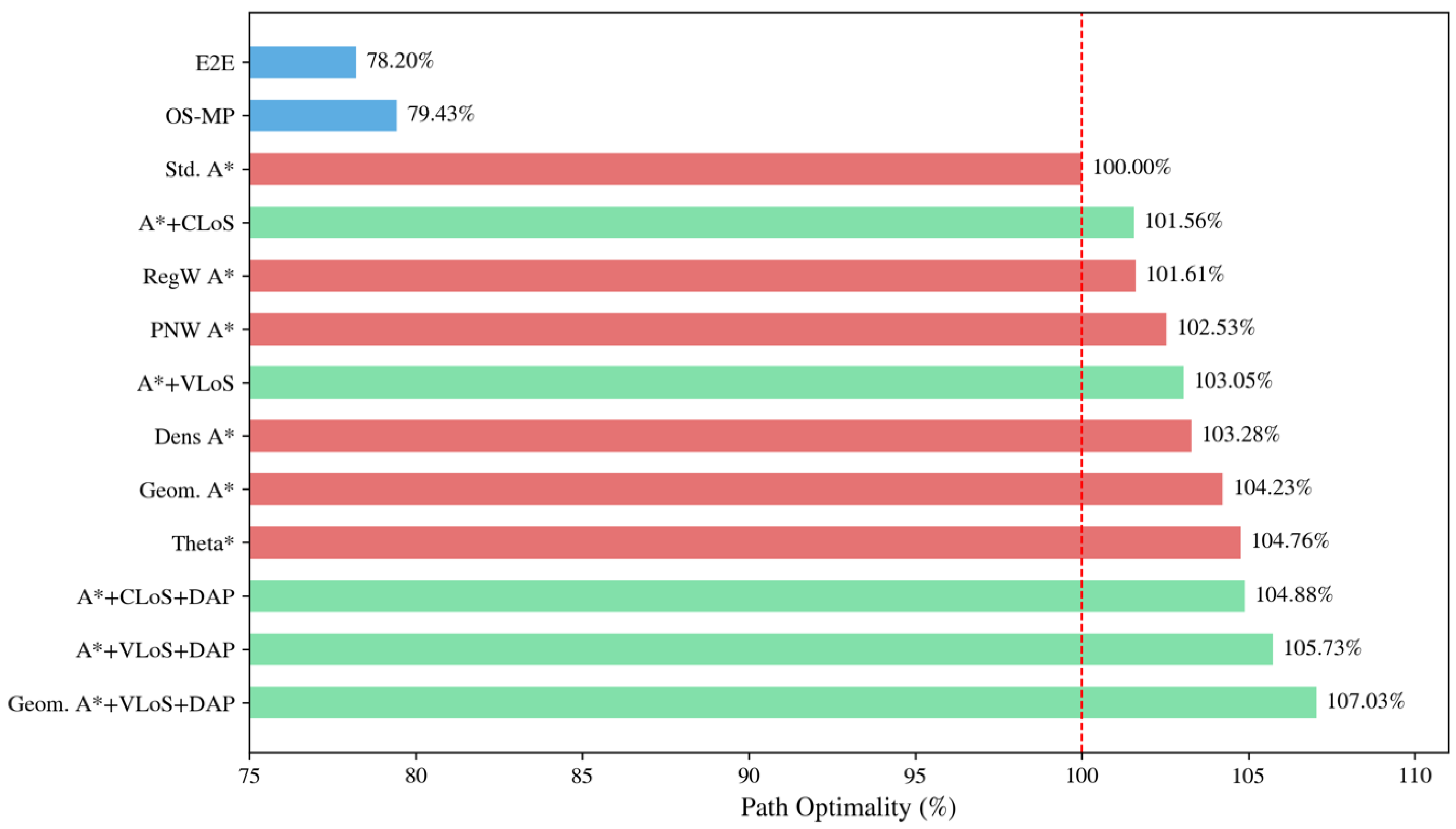
Figure 6 compares the path optimality of various algorithms on the maze dataset, with standard A* serving as the 100% baseline. Learning-based methods such as E2E-OSPPNet and OS-MPNet achieve only 78.20% and 79.43% of A* optimality, respectively, revealing a significant gap of over 20% relative to A*. In contrast, the proposed post-processing techniques outperform A* by producing shorter and smoother paths, with CLoSPO and VLoSPS achieving optimality of 101.56% and 103.05%, respectively. These improvements become even more pronounced when combined with DAPPA, reaching 104.88% and 105.73% for CLoSPO + DAPPA and VLoSPS + DAPPA, respectively.
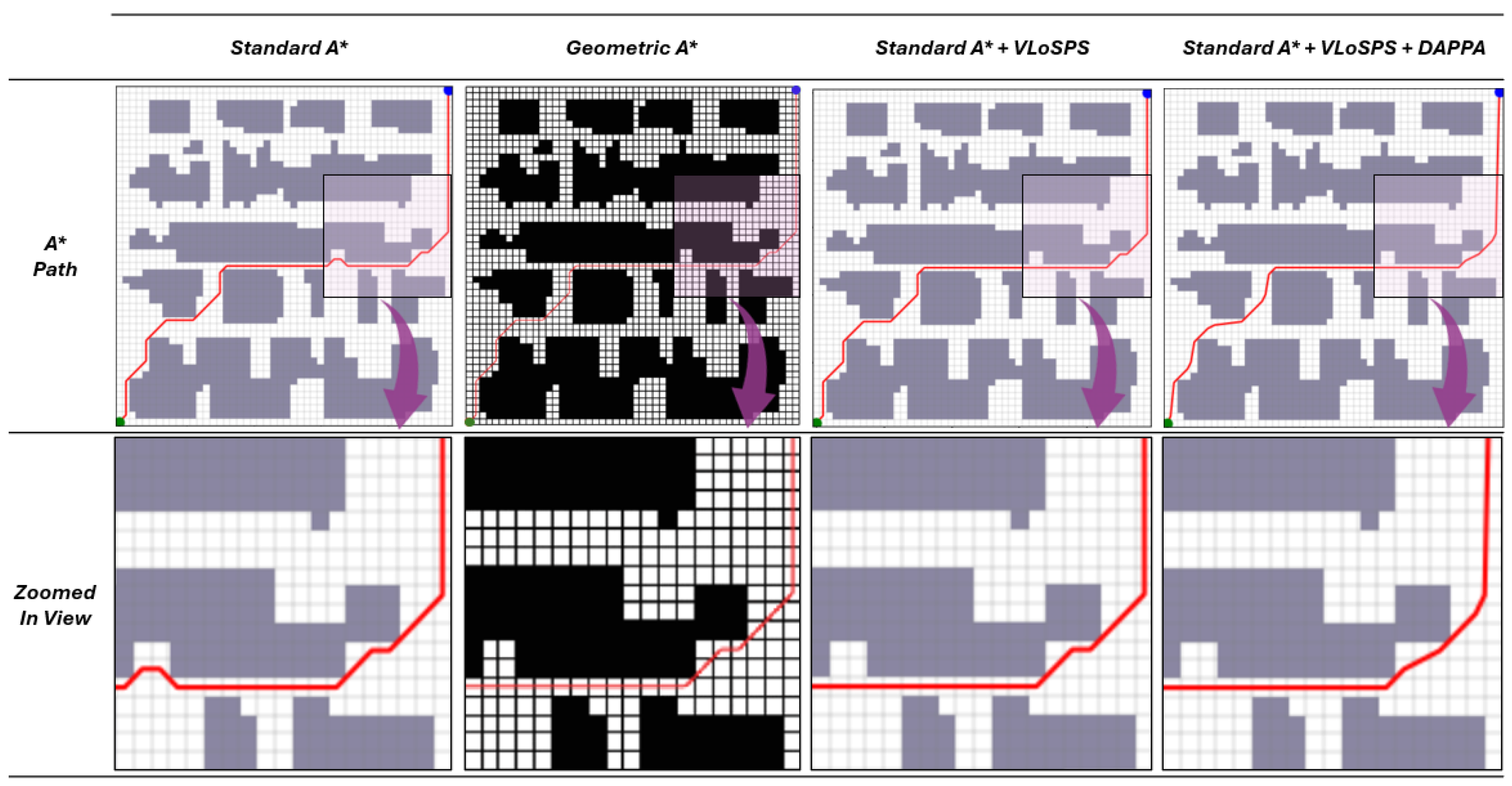
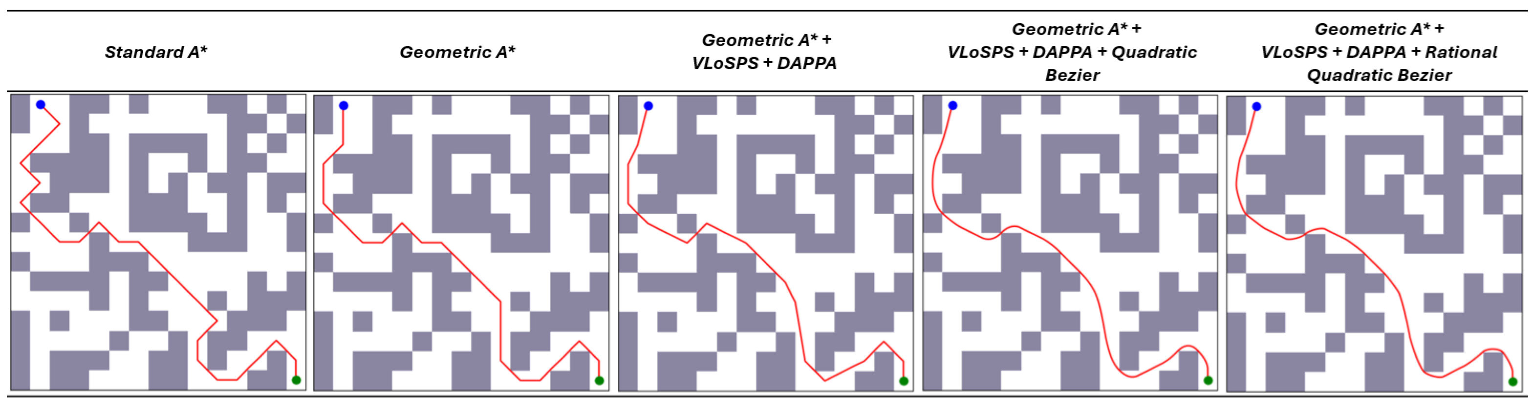
We also benchmarked the proposed method against RegW A*, PNW A*, Dens A*, Geom. A* and Theta* as described in [30], [29], [31], [13], and [32] respectively. These methods improve standard A* through different path optimization and post-processing techniques. On the Göttingen Maze Dataset, RegW A* achieved a path optimality of 101.61% with an average path length of 17.98 units, while PNW A* achieved 102.53% optimality with an average path length of 17.82 units. Dens A* further improved the result, achieving 103.28% path optimality and an average path length of 17.69 units. Geom. A* obtained 104.23% path optimality with an average path length of 17.53 units, whereas Theta* achieved 104.76% path optimality with an average path length of 17.44 units. These results indicate that the selected benchmark methods progressively improve upon standard A* by reducing path length and improving path optimality through different refinement mechanisms. In comparison, VLoSPS produced path lengths comparable to those generated by Geom. A*, as illustrated in Figure 7. Moreover, when VLoSPS and DAPPA were applied as post-processing stages to Geom. A*, the resulting pipeline achieved the shortest average path length of 17.07 units and the highest path optimality of 107.03%.
The combination of Geom. A* with VLoSPS and DAPPA produced further reductions in path length and improved path smoothness, as illustrated in Figure 8. Additional path improvement can also be obtained through Bézier-based curve smoothing, as demonstrated in our previous work [60], independent of the initial planning algorithm or post-processing configuration. In contrast to existing baseline methods and recent A*-based approaches that are designed for specific search mechanisms, the proposed VLoSPS and DAPPA pipeline provides a generalized post-processing pipeline for refining paths generated by different grid-based planning algorithms. This algorithm-independent formulation improves its applicability across diverse path planning methods and demonstrates its effectiveness in producing shorter, smoother, and geometrically more consistent paths compared with standard heuristic-based and learning-based methods.

6.2.3. Comparison of Average Path Lengths on Real-World Semantically Segmented Image Datasets

The results in Table 3 demonstrate the effectiveness of the proposed post-processing techniques, VLoSPS and DAPPA, in reducing the average path lengths across multiple real-world semantically segmented image datasets. For the dataset from [61], A*’s initial average path length of 1187.89 units is reduced to 1164.64 units after applying VLoSPS, a 1.96% reduction. Further refinement with DAPPA decreases the path length to 1129.33 units, corresponding to a total reduction of 4.93%. Similarly, Dijkstra exhibits a reduction from 1198.08 units to 1166.91 units (2.60%) with VLoSPS, and a further decrease to 1132.62 units (5.46%) after DAPPA. Significantly, BFS shows no improvement with VLoSPS alone, maintaining a path length of 1412.97 units, but experiences a substantial 16.41% reduction after the combined VLoSPS + DAPPA processing, decreasing the path length to 1181.05 units.
The results further demonstrate consistent improvements on the [58,59] datasets. In the [58] dataset, A* and Dijkstra achieve total path length reductions of 4.11% and 4.63%, respectively, following the application of both VLoSPS and DAPPA. BFS, while unaffected by VLoSPS alone, shows a notable 15.00% reduction after full post-processing. Similarly, in the [59] dataset, A* and Dijkstra achieve overall reductions of 5.13% and 5.75%, respectively, while BFS exhibits the most substantial improvement of 17.38%. DFS was not applied to these datasets due to the high spatial resolution of the semantically segmented images. In the processing pipeline, these images are converted into binary occupancy grids, resulting in large maze dimensions. Given the DFS strategy, where it recursively explores each branch to its maximum depth before backtracking, the algorithm becomes computationally intensive and inefficient in such expansive environments. As a result, path generation using DFS in these high-resolution grid maps imposes significant memory and processing demands, rendering it impractical for these datasets.

6.3. Real-Time Computational Performance Analysis

The computational performance of the path planning and optimization stages was analyzed using the same Göttingen Maze Dataset to assess the practical applicability of the proposed framework. The baseline path search stage produced total execution times of 3.006 s , 4.910 s , 3.337 s , and 3.837 s for A*, Dijkstra, BFS, and DFS, respectively, over the complete dataset. These results indicate that the primary computational cost is dominated by the initial graph traversal and path discovery stage.
The additional computational overhead introduced by the proposed VLoSPS and DAPPA stages remained comparatively low across most planning algorithms. The VLoSPS stage required 0.136 s , 0.127 s , 0.148 s , and 0.879 s for A*, Dijkstra, BFS, and DFS, respectively. Similarly, the DAPPA refinement stage required 0.188 s , 0.197 s , 0.150 s , and 0.187 s for A*, Dijkstra, BFS, and DFS, respectively. DFS produced a comparatively higher VLoSPS execution time due to the larger number of redundant intermediate path segments generated during the initial traversal stage. These observations indicate that the proposed pipeline introduces only limited computational overhead compared with the baseline path planning process, highlighting its suitability for real-time UAV-assisted navigation and path optimization.

6.4. Visualization of Path Planning on UAV-Derived Map Sequences

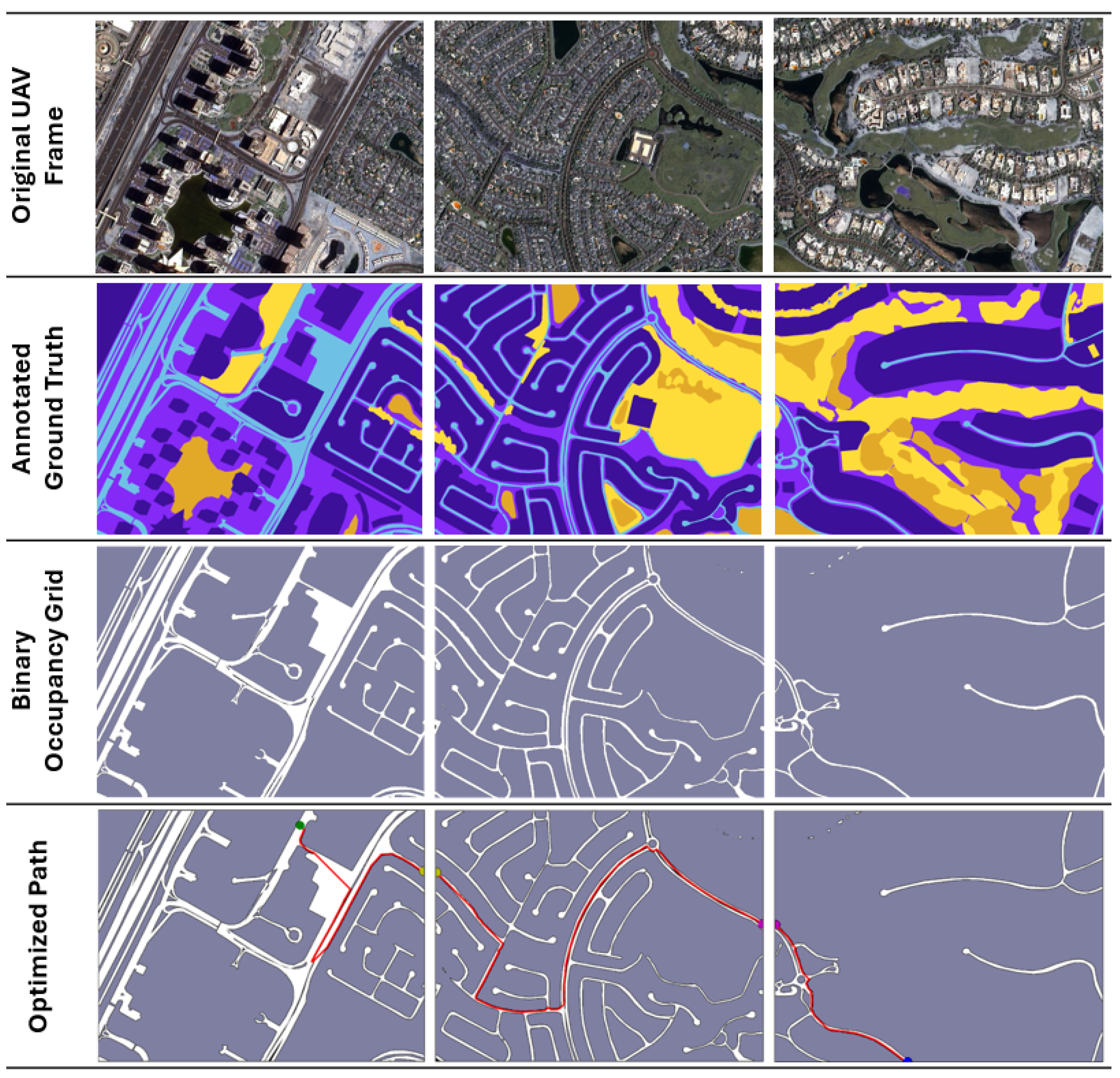
A sequence of aerial image frames captured by the UAV is processed through a pipeline to compute locally optimal paths within each frame as illustrated in Figure 9. In this approach, specific source and destination points are defined per frame, and a path planning algorithm is executed independently on each frame to generate a feasible path. This frame-wise strategy decomposes the global navigation task into a series of localized sub-problems, allowing the UGV to incrementally progress toward its overall objective. The system attains real-time situational awareness, enhancing decision-making at each planning step by using the high vantage point and wide field of view of the UAV.
The selected real-world datasets provide complementary aerial perspectives for evaluating the proposed path planning pipeline. The MBRSC Dubai Aerial Dataset represents satellite-based urban imagery from Dubai, including structured road networks, residential regions, vegetation, water bodies, and mixed-use infrastructure, supporting large-scale road-mask generation and global path planning analysis. The ISPRS Urban Semantic Dataset provides high-resolution airborne orthophotography from Vaihingen and Potsdam in Germany, enabling evaluation in dense urban scenes with complex morphology and detailed semantic annotations. The UAVid Dataset further contributes UAV-captured oblique-view imagery obtained using UAV-mounted 4K cameras, containing roads, buildings, vegetation, moving vehicles, and pedestrians in temporal urban sequences. Therefore, the evaluation covers satellite, airborne, and UAV-mounted visual data, allowing the proposed pipeline to be assessed under realistic sensing conditions, diverse urban structures, and practical UAV-assisted navigation scenarios.
Although the resulting path segments may not always constitute a globally optimal solution across the entire sequence, they remain sufficiently efficient for deployment in partially known environments. This provides scalable UAV-UGV collaboration by distributing computational responsibilities and making informed local decisions based on current visual input. In addition, combining the higher, broader perspective of the UAV with the limited upward view from the ground-level UGV enables more effective navigation through complex terrain, as the complementary perspectives facilitate selecting safer, more efficient paths. Consequently, the UGV can traverse challenging environments under the direction of the UAV, benefiting from a robust, cooperative framework.

7. Discussion and Conclusions

This study proposed a modular path planning optimization framework for UGVs operating in UAV-assisted navigation environments. The framework addresses key limitations of classical grid-based path planning algorithms, including redundant waypoint generation, excessive path length, and sharp directional changes. The proposed pipeline transforms UAV-captured or semantically segmented imagery into binary occupancy maps and applies classical graph-based planners, followed by a two-stage post-processing approach composed of VLoSPS and DAPPA. The principal innovation of this work is the development of VLoSPS, an algorithm-independent and visibility-aware waypoint reduction method that performs long-range axis-aligned line-of-sight analysis to eliminate redundant path segments. The integration of DAPPA further improves the geometric structure of the resulting path by reducing angular deviations and improving directional continuity.
The experimental results confirm the effectiveness and general applicability of the proposed framework across both synthetic and real-world navigation scenarios. Evaluations conducted on benchmark maze datasets and UAV-derived semantically segmented datasets demonstrate that the proposed post-processing pipeline consistently improves path efficiency across multiple baseline algorithms, including A*, Dijkstra, BFS, and DFS. On the Göttingen Maze Dataset, the combined VLoSPS and DAPPA pipeline reduced the average path lengths of A*, Dijkstra, BFS, and DFS by 5.42%, 9.46%, 10.44%, and 86.00%, respectively, relative to their standard implementations. These results indicate that the proposed method provides measurable improvements even for already efficient planners such as A* and Dijkstra, producing substantial reductions for less optimal search strategies such as DFS. The results obtained from real-world semantically segmented datasets further demonstrate the practical relevance of the approach for UAV-assisted UGV navigation in complex urban and aerial–ground collaborative environments.
A further academic contribution of this study is the comparative evaluation of VLoSPS against the previously introduced CLoSPO algorithm. The results show that VLoSPS achieves better path optimality by selecting the farthest visible waypoint at each simplification step, facilitating more effective reduction in redundant intermediate nodes. In terms of relative path optimality, VLoSPS combined with DAPPA achieved up to 105.73% compared with the standard A* baseline of 100%, while CLoSPO with DAPPA achieved 104.88% and CLoSPO alone achieved 101.56%. This improvement establishes VLoSPS as a more effective visibility-aware path simplification method and validates its contribution as a generalized post-processing method for grid-based path planning.
This work also contributes to reproducible research by releasing semantic-to-binary converted versions of three UAV imagery datasets and a newly generated synthetic maze dataset containing 6000 binary maze images across four grid resolutions. These datasets provide structured resources for evaluating path planning and post-processing algorithms under both controlled and realistic conditions. In conclusion, the proposed VLoSPS and DAPPA framework advances classical grid-based path planning by providing an algorithm-independent, computationally practical, and experimentally validated approach for improving path optimality, compactness, and navigability. The codebase and benchmark resources developed for this study are publicly available on GitHub [62], supporting reproducibility, independent validation, and further research. As the current approach is developed using UAV-derived two-dimensional occupancy maps, future work can further improve its adaptability by combining dynamic obstacle awareness, terrain-aware cost modeling, and real-time map updating. In addition, real UGV navigation using UAV-derived maps is currently being developed as part of our ongoing work to further validate the framework in physical robotic environments. These extensions would further strengthen the applicability of the framework to practical UAV-UGV collaborative scenarios, including search and rescue, disaster monitoring, agricultural field navigation, and autonomous navigation in partially known environments.

Author Contributions

I.M., A.P., S.A. and M.G. conceptualized the study. I.M. and A.P. developed the methodology. I.M. conducted the experiments and wrote the manuscript. A.P., S.A. and M.G. provided supervision, critical feedback, and comments, contributing to the review and editing of the manuscript. All authors reviewed and approved the final version of the manuscript.

Funding

This research received no external funding.

Data Availability Statement

The codebase and benchmark resources developed and used in this study are publicly available in the DAPPA-VLoSPS Maze Planning project repository on GitHub.

Acknowledgments

Grammarly (https://www.grammarly.com/, accessed on 10 April 2026) has been used to correct minor grammar errors.

Conflicts of Interest

The authors declare no conflicts of interest.

References

  1. AbuJabal, N.; Rabie, T.; Baziyad, M.; Kamel, I.; Almazrouei, K. Path Planning Techniques for Real-Time Multi-Robot Systems: A Systematic Review. Electronics 2024, 13, 2239. [Google Scholar] [CrossRef]
  2. Qin, H.; Meng, Z.; Meng, W.; Chen, X.; Sun, H.; Lin, F.; Ang, M.H. Autonomous Exploration and Mapping System Using Heterogeneous UAVs and UGVs in GPS-Denied Environments. IEEE Trans. Veh. Technol. 2019, 68, 1339–1350. [Google Scholar] [CrossRef]
  3. Munasinghe, I.; Vijenayake, V.; Viduranga, S.; Lokugama, Y.; Jayasekara, P. Design and Implementation of a Semi-Autonomous Robotic System for Systematic Solar Panel Cleaning. In Proceedings of the 2024 9th International Conference on Control and Robotics Engineering (ICCRE); IEEE: New York, NY, USA, 2024; pp. 61–67. [Google Scholar]
  4. Munasinghe, I.; Vijenayake, V.; Jayasekara, P. Improving navigation of a semi-autonomous solar panel cleaning robot through advanced localization and edge detection. Int. J. Sci. Eng. Manag. (IJSEM) 2025, 12, 9–14. [Google Scholar] [CrossRef]
  5. Niu, G.; Wu, L.; Gao, Y.; Pun, M.O. Unmanned Aerial Vehicle (UAV)-Assisted Path Planning for Unmanned Ground Vehicles (UGVs) via Disciplined Convex-Concave Programming. IEEE Trans. Veh. Technol. 2022, 71, 6996–7007. [Google Scholar] [CrossRef]
  6. Munasinghe, I.; Perera, A.; Deo, R.C. A Comprehensive Review of UAV-UGV Collaboration: Advancements and Challenges. J. Sens. Actuator Netw. 2024, 13, 81. [Google Scholar] [CrossRef]
  7. Li, J.; Deng, G.; Luo, C.; Lin, Q.; Yan, Q.; Ming, Z. A Hybrid Path Planning Method in Unmanned Air/Ground Vehicle (UAV/UGV) Cooperative Systems. IEEE Trans. Veh. Technol. 2016, 65, 9585–9596. [Google Scholar] [CrossRef]
  8. Meng, W.; Zhang, X.; Zhou, L.; Guo, H.; Hu, X. Advances in UAV Path Planning: A Comprehensive Review of Methods, Challenges, and Future Directions. Drones 2025, 9, 376. [Google Scholar] [CrossRef]
  9. Guan, Q.; Cao, H.; Tan, J.; Ou, B.; Wang, Y.; Yan, X.; Chen, B. Dynamic-aware deep reinforcement learning for heterogeneous fleet-based capacitated electric vehicle routing problems. Appl. Energy 2026, 413, 127757. [Google Scholar] [CrossRef]
  10. Guan, Q.; Xue, S.; Tan, J.; Jia, L.; Cao, H.; Chen, B. Dynamic embedding-based deep reinforcement learning for heterogeneous capacitated VRPs with unloading time constraints. Expert Syst. Appl. 2025, 293, 128660. [Google Scholar] [CrossRef]
  11. Elkari, B.; Ourabah, L.; Sekkat, H.; Hsaine, A.; Essaiouad, C.; Bouargane, Y.; El Moutaouakil, K. Exploring Maze Navigation: A Comparative Study of DFS, BFS, and A* Search Algorithms. Stat. Optim. Inf. Comput. 2024, 12, 761–781. [Google Scholar] [CrossRef]
  12. Rachmawati, D.; Gustin, L. Analysis of Dijkstra’s algorithm and A* algorithm in shortest path problem. Proc. J. Phys. Conf. Ser. 2020, 1566, 012061. [Google Scholar] [CrossRef]
  13. Tang, G.; Tang, C.; Claramunt, C.; Hu, X.; Zhou, P. Geometric A-star algorithm: An improved A-star algorithm for AGV path planning in a port environment. IEEE Access 2021, 9, 59196–59210. [Google Scholar] [CrossRef]
  14. Ugwoke, K.C.; Nnanna, N.A.; Abdullahi, S.E.Y. Simulation-based review of classical, heuristic, and metaheuristic path planning algorithms. Sci. Rep. 2025, 15, 12643. [Google Scholar] [CrossRef] [PubMed]
  15. Paulino, L.; Hannum, C.; Varde, A.S.; Conti, C.J. Search methods in motion planning for mobile robots. In Proceedings of the Intelligent Systems and Applications: Proceedings of the 2021 Intelligent Systems Conference (IntelliSys); Springer: Berlin/Heidelberg, Germany, 2022; Volume 3, pp. 802–822. [Google Scholar]
  16. Godara, S.; Sikka, G.; Parsad, R.; Marwaha, S.; Faiz, M.A.; Bana, R.S. Pony: Leveraging m-graphs and Pruned-BFS Algorithm to Elevate AI-Powered Low-Cost Self-Driving Robotics. IEEE Access 2024, 12, 134185–134197. [Google Scholar] [CrossRef]
  17. Ryu, H.; Chung, W.K. Local map-based exploration using a breadth-first search algorithm for mobile robots. Int. J. Precis. Eng. Manuf. 2015, 16, 2073–2080. [Google Scholar] [CrossRef]
  18. Tripathy, H.K.; Mishra, S.; Thakkar, H.K.; Rai, D. CARE: A collision-aware mobile robot navigation in grid environment using improved breadth first search. Comput. Electr. Eng. 2021, 94, 107327. [Google Scholar] [CrossRef]
  19. Indriyono, B.V.; Widyatmoko. Optimization of breadth-first search algorithm for path solutions in mazyin games. Int. J. Artif. Intell. Robot. (IJAIR) 2021, 3, 58–66. [Google Scholar] [CrossRef]
  20. Emelianov, S.G.; Bobyr, M.V.; Kryukov, A.G. Research of the Properties of the Breadth-First Search Algorithm for Finding the Movement Route of Robots; Southwest State University: Marshall, MN, USA, 2022; p. 40. [Google Scholar]
  21. Lim, T.; Ng, P.L. Evaluating recursive backtracking depth-first search algorithm in unknown search space for self-learning path finding robot. In Proceedings of the International Conference on Artificial Intelligence for Communications and Networks; Springer: Berlin/Heidelberg, Germany, 2020; pp. 531–543. [Google Scholar]
  22. Munasinghe, I.; Rodrigo, A.; Perera, A. Experimental Evaluation of Grid-Based Path Planning Algorithms for Mobile Robot Navigation. In Proceedings of the 2025 IEEE 19th International Conference on Industrial and Information Systems (ICIIS); IEEE: New York, NY, USA, 2026; Volume 19, pp. 358–363. [Google Scholar]
  23. Zhang, D.; Chen, C.; Zhang, G. AGV path planning based on improved A-star algorithm. In Proceedings of the 2024 IEEE 7th Advanced Information Technology, Electronic and Automation Control Conference (IAEAC); IEEE: New York, NY, USA, 2024; Volume 7, pp. 1590–1595. [Google Scholar]
  24. Xu, B. Precise path planning and trajectory tracking based on improved A-star algorithm. Meas. Control 2024, 57, 1025–1037. [Google Scholar] [CrossRef]
  25. Chen, J.; Li, M.; Yuan, Z.; Gu, Q. An improved A* algorithm for UAV path planning problems. In Proceedings of the 2020 IEEE 4th Information Technology, Networking, Electronic and Automation Control Conference (ITNEC); IEEE: New York, NY, USA, 2020; Volume 1, pp. 958–962. [Google Scholar]
  26. Luo, M.; Hou, X.; Yang, J. Surface optimal path planning using an extended Dijkstra algorithm. IEEE Access 2020, 8, 147827–147838. [Google Scholar] [CrossRef]
  27. Dhulkefl, E.; Durdu, A.; Terzioğlu, H. Dijkstra algorithm using UAV path planning. Konya J. Eng. Sci. 2020, 8, 92–105. [Google Scholar] [CrossRef]
  28. Sun, Y.; Fang, M.; Su, Y. AGV path planning based on improved Dijkstra algorithm. Proc. J. Phys. Conf. Ser. 2021, 1746, 012052. [Google Scholar] [CrossRef]
  29. Lin, M.; Yuan, K.; Shi, C.; Wang, Y. Path planning of mobile robot based on improved A* algorithm. In Proceedings of the 2017 29th Chinese Control And Decision Conference (CCDC), Chongqing, China, 28–30 May 2017; pp. 3570–3576. [Google Scholar] [CrossRef]
  30. Li, Y.; Wang, Z.; Zhang, S. Path Planning of Robots Based on an Improved A-star Algorithm. In Proceedings of the 2022 IEEE 5th Advanced Information Management, Communicates, Electronic and Automation Control Conference (IMCEC), Chongqing, China, 16–18 December 2022; IEEE: New York, NY, USA; Volume 5, pp. 826–831. [CrossRef]
  31. Luo, Y.; Lin, S.; Wang, Y.; Liang, K. Optimized Path Planning for Autonomous Guided Vehicle Through Fusion of Improved A* and Dynamic Window Approach. IEEE Access 2025, 13, 68577–68586. [Google Scholar] [CrossRef]
  32. Nash, A.; Daniel, K.; Koenig, S.; Felner, A. Theta*: Any-angle path planning on grids. Proc. AAAI 2007, 7, 1177–1183. [Google Scholar]
  33. Ušinskis, V.; Nowicki, M.; Dzedzickis, A.; Bučinskas, V. Sensor-fusion based navigation for autonomous mobile robot. Sensors 2025, 25, 1248. [Google Scholar] [CrossRef]
  34. Yu, Z.; Li, J.; Wei, Y.; Lyu, Y.; Tan, X. Combining Camera–LiDAR Fusion and Motion Planning Using Bird’s-Eye View Representation for End-to-End Autonomous Driving. Drones 2025, 9, 281. [Google Scholar] [CrossRef]
  35. Meng, X.; Fang, X. A UGV Path Planning Algorithm Based on Improved A* with Improved Artificial Potential Field. Electronics 2024, 13, 972. [Google Scholar] [CrossRef]
  36. Shoeib, M.A.; Lewandowski, J.; Omara, A.M. A novel methodology for vision-based path planning and obstacle avoidance in mobile robot applications. Adv. Robot. 2024, 38, 802–817. [Google Scholar] [CrossRef]
  37. Zhou, R.; Zhou, K.; Wang, L.; Wang, B. An improved dynamic window path planning algorithm using multi-algorithm fusion. Int. J. Control Autom. Syst. 2024, 22, 1005–1020. [Google Scholar] [CrossRef]
  38. Schneider, L.; Frey, J.; Miki, T.; Hutter, M. Learning risk-aware quadrupedal locomotion using distributional reinforcement learning. In Proceedings of the 2024 IEEE International Conference on Robotics and Automation (ICRA); IEEE: New York, NY, USA, 2024; pp. 11451–11458. [Google Scholar]
  39. Hu, C.; Liu, D.; Wang, Z.; Li, D.; Wang, J.; Tang, X. Risk-aware reinforcement learning for non-conservative motion planning in uncertain autonomous driving environments. IEEE Trans. Intell. Transp. Syst. 2025, 26, 18880–18893. [Google Scholar] [CrossRef]
  40. Wang, J.; Wang, J.; Chen, R.; Yang, K.; Wu, B.; Qi, Y. Formation collaborative obstacle avoidance with multiple UGVs in restricted environments based on adaptive DWA. Expert Syst. Appl. 2025, 265, 125870. [Google Scholar] [CrossRef]
  41. Han, R.; Chen, S.; Hao, Q. Cooperative multi-robot navigation in dynamic environment with deep reinforcement learning. In Proceedings of the 2020 IEEE International Conference on Robotics and Automation (ICRA); IEEE: New York, NY, USA, 2020; pp. 448–454. [Google Scholar]
  42. Zhang, H.; Wang, Y.; Zheng, J.; Yu, J. Path planning of industrial robot based on improved RRT algorithm in complex environments. IEEE Access 2018, 6, 53296–53306. [Google Scholar] [CrossRef]
  43. Suwoyo, H.; Adriansyah, A.; Andika, J.; Ubaidillah, A.; Zakaria, M.F. An Integrated RRT* SMART-A* Algorithm for solving the Global Path Planning Problem in a Static Environment. IIUM Eng. J. 2023, 24, 269–284. [Google Scholar] [CrossRef]
  44. Rasheed, A.A.A.; Al-Araji, A.S.; Abdullah, M.N. Static and dynamic path planning algorithms design for a wheeled mobile robot based on a hybrid technique. Int. J. Intell. Eng. Syst. 2022, 15, 167–181. [Google Scholar] [CrossRef]
  45. Yang, K.; Moon, S.; Yoo, S.; Kang, J.; Doh, N.L.; Kim, H.B.; Joo, S. Spline-based RRT path planner for non-holonomic robots. J. Intell. Robot. Syst. 2014, 73, 763–782. [Google Scholar] [CrossRef]
  46. Liu, B.; Feng, W.; Li, T.; Hu, C.; Zhang, J. A variable-step RRT* path planning algorithm for quadrotors in below-canopy. IEEE Access 2020, 8, 62980–62989. [Google Scholar] [CrossRef]
  47. Tang, C.; Peng, T.; Xie, X.; Peng, J. 3D path planning of unmanned ground vehicles based on improved DDQN. J. Supercomput. 2025, 81, 276. [Google Scholar] [CrossRef]
  48. Carvalho, A.E.; Ferreira, J.F.; Portugal, D. 3D traversability analysis and path planning based on mechanical effort for UGVs in forest environments. Robot. Auton. Syst. 2024, 171, 104560. [Google Scholar] [CrossRef]
  49. Ruetz, F.; Borges, P.; Suenderhauf, N.; Hernández, E.; Peynot, T. Forest traversability mapping (FTM): Traversability estimation using 3D voxel-based normal distributed transform to enable forest navigation. In Proceedings of the 2022 IEEE/RSJ International Conference on Intelligent Robots and Systems (IROS); IEEE: New York, NY, USA, 2022; pp. 8714–8721. [Google Scholar]
  50. Sucan, I.A.; Moll, M.; Kavraki, L.E. The Open Motion Planning Library. IEEE Robot. Autom. Mag. 2012, 19, 72–82. [Google Scholar] [CrossRef]
  51. Geraerts, R.; Overmars, M.H. Clearance based path optimization for motion planning. In Proceedings of the IEEE International Conference on Robotics and Automation, 2004; Proceedings, ICRA’04; IEEE: New York, NY, USA, 2004; Volume 3, pp. 2386–2392. [Google Scholar]
  52. Xu, B.; Wang, N.; Sanfelice, R.G. cHyRRT and cHySST: Motion Planning Tools for Hybrid Dynamical Systems in OMPL. In Proceedings of the 2025 IEEE 21st International Conference on Automation Science and Engineering (CASE), Los Angeles, CA, USA, 17–21 August 2025; pp. 1640–1645. [Google Scholar]
  53. Schulman, J.; Duan, Y.; Ho, J.; Lee, A.; Awwal, I.; Bradlow, H.; Pan, J.; Patil, S.; Goldberg, K.; Abbeel, P. Motion planning with sequential convex optimization and convex collision checking. Int. J. Robot. Res. 2014, 33, 1251–1270. [Google Scholar] [CrossRef]
  54. Vincent, L. Morphological algorithms. In Mathematical Morphology in Image Processing; CRC Press: Boca Raton, FL, USA, 2018; pp. 255–288. [Google Scholar]
  55. Pesaresi, M.; Benediktsson, J. A new approach for the morphological segmentation of high-resolution satellite imagery. IEEE Trans. Geosci. Remote Sens. 2001, 39, 309–320. [Google Scholar] [CrossRef]
  56. Loop, H. Semantic Segmentation of Aerial Imagery. 2020. Available online: https://www.kaggle.com/datasets/humansintheloop/semantic-segmentation-of-aerial-imagery (accessed on 1 January 2026).
  57. Rottensteiner, F.; Sohn, G.; Gerke, M.; Wegner, J.D.; Breitkopf, U.; Jung, J. Results of the ISPRS benchmark on urban object detection and 3D building reconstruction. ISPRS J. Photogramm. Remote Sens. 2014, 93, 256–271. [Google Scholar] [CrossRef]
  58. ISPRS Working Groups III/4 and II/4. ISPRS Test Project on Urban Classification, 3D Building Reconstruction and Semantic Labeling. 2012–2022. Available online: https://www.isprs.org/resources/datasets/benchmarks/UrbanSemLab/default.aspx (accessed on 1 January 2026).
  59. Lyu, Y.; Vosselman, G.; Xia, G.; Yilmaz, A.; Yang, M.Y. UAVid: A Semantic Segmentation Dataset for UAV Imagery. ISPRS J. Photogramm. Remote Sens. 2020, 165, 108–119. [Google Scholar] [CrossRef]
  60. Munasinghe, I.; Perera, A.; Anavatti, S.; Garratt, M. Direction-Aware and Line of Sight Constrained Path Planning with Bézier Curve Smoothing for High-Resolution Maze Traversal. ResearchGate 2025. [Google Scholar] [CrossRef]
  61. Computational Neuroscience Group, University of Göttingen. Path Planning Using Deep Learning. Available online: https://alexandria.physik3.uni-goettingen.de/cns-group/datasets/path_planning/ (accessed on 1 January 2026).
  62. Munasinghe, I. DAPPA-VLoSPS Maze Planning. 2025. Available online: https://github.com/IsuruMunasinghe98/dappa-vlosps-benchmark-datasets (accessed on 10 April 2026).
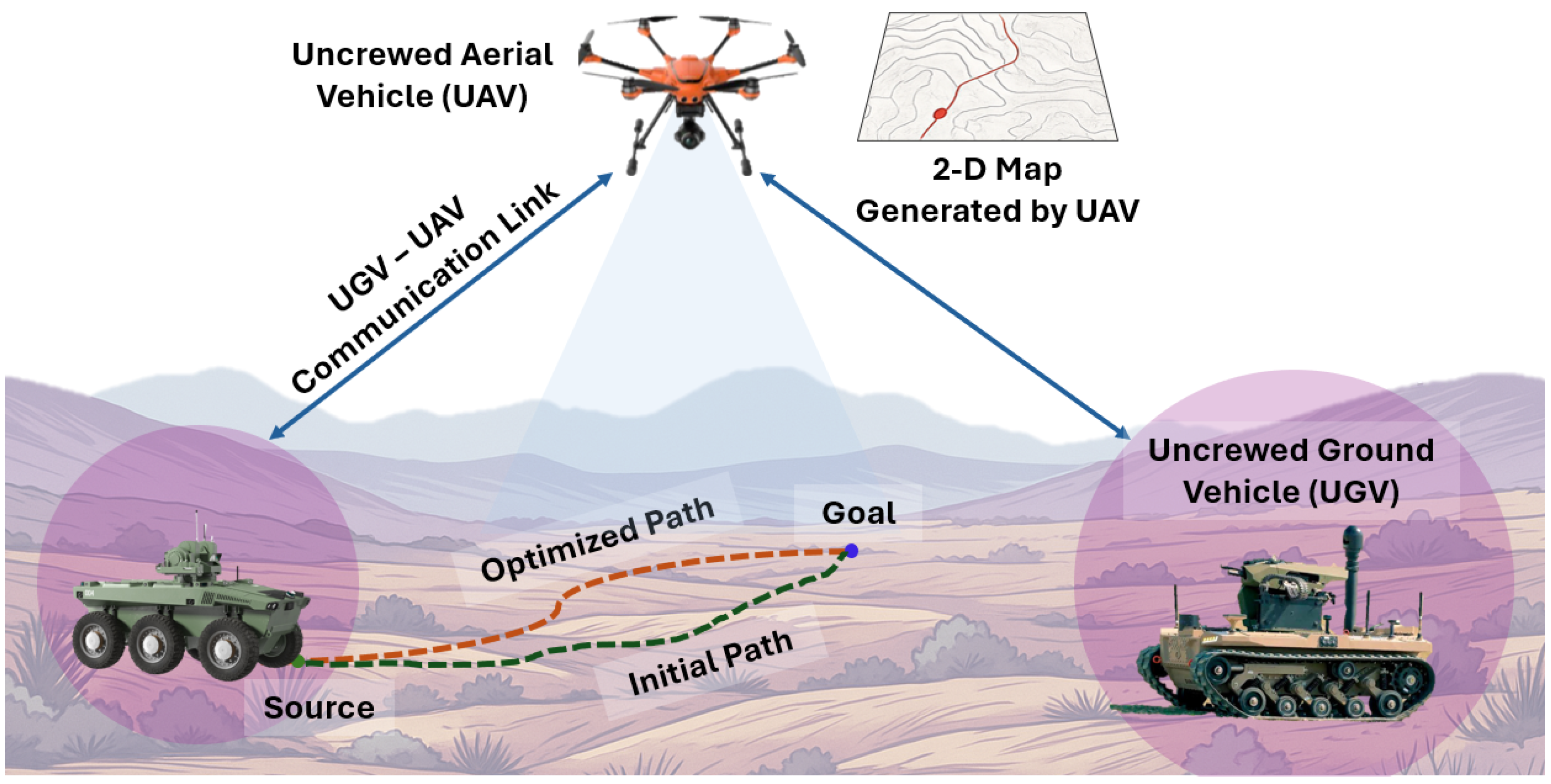
Figure 1. Overview of the proposed UAV-UGV collaborative framework, where UAV-captured aerial imagery is used to generate a 2D map and determine the optimized path length for guiding UGV navigation from source to goal.
Jsan 15 00041 g001
Figure 2. Proposed path planning pipeline demonstrating advanced improvements with VLoSPS and DAPPA post-processing. The blue and green dots denote the source and destination positions, respectively, while the red line represents the planned robot trajectory.
Jsan 15 00041 g002
Figure 3. DAPPA waypoint refinement: at each intermediate waypoint p i , the angle θ and adjusted point p new are computed using K to reduce sharp turns, remove redundancies, and produce a smoother trajectory. Purple dots indicate the original path waypoints, red dots indicate the refined waypoints after applying DAPPA, solid blue arrows represent the robot motion direction, and curved blue arrows indicate the directional change of the robot path corresponding to the rotation angle.
Jsan 15 00041 g003
Figure 4. Comparison of path simplification using CLoSPO and VLoSPS on a 30 × 30 maze grid image (std.: standard algorithm; +CLoSPO: CLoSPO simplification applied; +VLoSPS: VLoSPS simplification applied). The blue and green dots denote the source and destination positions, respectively, while the red line represents the planned robot trajectory. The black rectangular frames indicate the selected regions enlarged in the corresponding zoomed-in views.
Jsan 15 00041 g004
Figure 5. Visualization of paths generated by different path planning algorithms with VLoSPS and DAPPA post-processing and Bézier smoothing applied to a 30 × 30 maze image (std.: standard algorithm). The blue and green dots denote the source and destination positions, respectively, while the red line represents the planned robot trajectory. The black rectangular frames indicate the selected regions enlarged in the corresponding zoomed-in views.
Jsan 15 00041 g005
Figure 6. Comparison of path optimality (%) of various algorithms on maze datasets (Std. A*: Standard A* (baseline at 100%); E2E: E2E-OSPPNet; OS-MP: OS-MPNet; RegW A*: Region-Weighted A*; PNW A*: Parent-Node Weighted A*; Dens A*: Density-Aware A*; CLoS: CLoSPO; VLoS: VLoSPS; Geom. A*: Geometric A*; DAP: DAPPA). The red dotted vertical line indicates the 100% baseline corresponding to the standard A* algorithm.
Jsan 15 00041 g006
Figure 7. Comparison of path optimization on a 50 × 50 maze grid using Geom. A* [13], VLoSPS, and VLoSPS + DAPPA techniques. The blue and green dots denote the source and destination positions, respectively, while the red line represents the planned robot trajectory. The black rectangular frames indicate the selected regions enlarged in the corresponding zoomed-in views.
Jsan 15 00041 g007
Figure 8. Comparison of paths generated by Standard A*, Geom. A*, and Geom. A* enhanced with VLoSPS, DAPPA and Bézier smoothing (quadratic and rational quadratic) techniques. The blue and green dots denote the source and destination positions, respectively, while the red line represents the planned robot trajectory.
Jsan 15 00041 g008
Figure 9. Stitching multiple drone-captured images to form a larger map and applying the pipeline on each frame to generate an optimal goal-directed path. The blue and green dots denote the source and destination positions, respectively, while the red line represents the planned robot trajectory.
Jsan 15 00041 g009
Table 1. Comparative analysis of CLoSPO and VLoSPS algorithms based on their search strategies and suitable application scenarios in path simplification.
CriterionCLoSPOVLoSPS
Search StrategyIncremental forward search starting at the current point and advancing to the last visible point before encountering an obstacle.Global backward search beginning at the current position and evaluating the farthest visible point toward the goal.
Visibility ModelRestricts visibility strictly to axis-aligned directions (horizontal or vertical), terminating when an obstacle is detected.Considers axis-aligned visibility as well, but evaluates more broadly to identify the longest possible obstacle-free segment.
Path CompactnessProduces moderately simplified paths with locally optimized segments.Produces highly compact paths, resulting in fewer and more direct segments.
Computational ComplexityRelatively low, due to early termination upon violation of visibility constraints.Relatively high, as it performs exhaustive scanning to identify the farthest valid waypoint.
Robustness to Grid DensityMore effective in dense environments with frequent obstacles, where long unobstructed segments are scarce.More effective in sparse environments with longer clear paths that can be exploited.
Search BehaviorLocal and incremental, simplifying the path step by step with early termination at each obstacle.Global within the visibility scope, performing an exhaustive search to maximize segment simplification at each iteration.
Ideal Application ContextWell-suited for systems requiring gradual progression and constrained simplification, especially in cluttered environments.Suitable for systems that prioritize globally compact paths and reduced waypoint overhead, particularly in open environments.
Table 2. Comparison of path planning algorithms with proposed path optimization techniques on synthetic maze environments (N: number of maze samples; init. len.: initial path length in units; +VLoSPS: VLoSPS simplification applied; +VLoSPS+DAPPA: VLoSPS followed by DAPPA simplification; avg. len.: average path length in units; redu. (%): reduction percentage with respect to initial length).
DatasetMaze SizeNAlgo.Init. Len.+VLoSPS+VLoSPS + DAPPA
Avg. Len.Redu. (%)Avg. Len.Redu. (%)
Göttingen’s
Maze Dataset
[61]
30 × 30 2000A*18.2717.732.9617.285.42
Dij.19.2417.867.1417.429.46
BFS21.1321.130.0018.9210.44
DFS240.4437.7584.3033.6786.00
Maze Images
Dataset
[62]
10 × 10 1500A*10.3610.181.749.993.60
Dij.10.5110.222.7710.034.59
BFS18.3818.380.0015.4316.07
DFS28.8621.3026.2217.8138.30
30 × 30 1500A*32.7732.141.9131.483.93
Dij.33.0832.182.7131.574.56
BFS56.5256.520.0048.2014.72
DFS186.7679.5657.4067.2164.01
50 × 50 1500A*58.4757.441.7656.303.71
Dij.58.5657.232.2756.223.99
BFS89.9489.940.0077.0014.38
1294DFS432.61142.8666.98120.5972.13
100 × 100 1500A*123.82121.941.53119.523.48
Dij.123.07120.761.87118.693.56
BFS171.78171.780.00147.7414.00
431DFS508.13271.6346.54229.1854.90
Note: Bold values indicate the reduction percentages achieved using the complete proposed optimization pipeline (+VLoSPS + DAPPA).
Table 3. Comparison of path planning algorithms with proposed path optimization techniques for average path length on real-world semantically segmented images (N: number of image samples; init. len.: initial path length in units; +VLoSPS: VLoSPS simplification applied; +VLoSPS + DAPPA: VLoSPS followed by DAPPA simplification; avg. len.: average path length in units; redu. (%): reduction percentage with respect to initial length).
DatasetNAlgo.Init. Len.+VLoSPS+VLoSPS + DAPPA
Avg. Len.Redu. (%)Avg. Len.Redu. (%)
MBRSC Dubai
Aerial Dataset [56]
30A*1187.891164.641.961129.334.93
Dijkstra1198.081166.912.601132.625.46
BFS1412.971412.970.001181.0516.41
ISPRS Urban
Semantic Dataset [58]
71A*3284.563241.271.323149.644.11
Dijkstra3439.523362.992.233280.144.63
BFS4103.654103.650.003488.0915.00
UAVid Dataset [59]270A*1021.21996.222.45968.875.13
Dijkstra1040.471005.403.37980.625.75
BFS1236.451236.450.001021.5117.38
Note: Bold values indicate the reduction percentages achieved using the complete proposed optimization pipeline (+VLoSPS + DAPPA).
Disclaimer/Publisher’s Note: The statements, opinions and data contained in all publications are solely those of the individual author(s) and contributor(s) and not of MDPI and/or the editor(s). MDPI and/or the editor(s) disclaim responsibility for any injury to people or property resulting from any ideas, methods, instructions or products referred to in the content.