Article

Compact Bio-Inspired Terahertz Ultrawideband Antenna: A Viburnum tinus-Based Approach for 6G and Beyond Applications


by
Jeremiah O. Abolade
1,2,
Dominic B. O. Konditi
3,
Pradeep Kumar
4,* and
Grace Olaleru
2
1
Institute for Basic Sciences, Technology and Innovation, Department of Electrical Engineering, Pan African University, Nairobi 00200, Kenya
2
Department of Electrical and Electronic Engineering, Bowen University, Iwo 284, Nigeria
3
Department of Electrical and Electronic Engineering, The Technical University of Kenya, Nairobi 41540, Kenya
4
Discipline of Electrical, Electronic and Computer Engineering, University of KwaZulu-Natal, Durban 4041, South Africa
*
Author to whom correspondence should be addressed.
J. Sens. Actuator Netw. 2025, 14(6), 107; https://doi.org/10.3390/jsan14060107
Submission received: 1 September 2025 / Revised: 23 October 2025 / Accepted: 27 October 2025 / Published: 30 October 2025

Abstract

A compact bio-inspired terahertz wideband antenna is presented in this work. The proposed antenna is based on Viburnum tinus leaf shape, a defective ground plane, a folded-ring slot, and parasitic elements. The footprint of the proposed antenna is 0.46   ×   0.18   λ g 2  at 0.18 THz. A bandwidth of 0.536 THz (0.18–0.72 THz) is achieved with a band notch at 0.35 THz (0.3–0.36 THz). The proposed antenna has a peak gain of 5 dBi and the stable radiation patterns. The proposed antenna is validated through a finite difference time domain simulator and the equivalent circuit analysis. The results from show a good correlation. Also, an extensive parametric analysis is performed, and the comparative analysis of the proposed antenna with the existing antennas shows that the proposed antenna is compact with competitive performance metrics such as gain, efficiency, and notch-band characteristics. Therefore, the proposed antenna (hereafter referred to as VTB-A) is a promising candidate for future terahertz wireless communications (5G, 6G, and beyond) and terahertz imaging.

1. Introduction

Users’ demand for high-speed, seamless connectivity and desire for the Internet of Everything (IoE) have necessitated the need to explore higher frequency spectrum in the communication community. The terahertz frequency band is being considered as a promising spectrum for the future 6G and beyond communication and terahertz imaging due to its unmatchable bandwidth, penetrating capacity, and undetectability to human eyes [1,2,3,4]. Its potential ability to provide an unprecedented data rate (terabit-per-second link capacities) in communications networks, compact transceivers, and appreciable energy efficiency is making the terahertz band (0.1–10 THz) gain prominence in the wireless communication community [4,5]. The terahertz band is the enabler of Beyond 5G (B5G) and 6G wireless communications [3]. Antenna is a critical part of wireless communication, including terahertz communication. Although terahertz antenna design and development are still at their infant level due to the miniature size and unavailability of advanced fabrication techniques suitable for such a nanostructure, significant progress has been made so far [1].
In recent times, researchers attention has been shifted to the design and development of terahertz antennas as the enabler of terahertz systems [5,6,7,8,9,10,11,12,13]. Terahertz antennas enable advanced sensing and communication capabilities crucial for the sensor networks. Antennas operating in the terahertz frequency range support high-resolution imaging and spectroscopic identification of materials, which is valuable in biomedical applications, nondestructive testing, and environmental monitoring. In addition, terahertz antennas provide ultra-high bandwidth communication for fast data transfer in dense sensor networks, which therefore facilitates real-time monitoring and control. Moreover, the compactness of terahertz antennas makes them an ideal component for integrated sensor-actuator networks, Internet-of-Things (IoT) systems, and smart environments [2,4]. Terahertz antenna developments can be classified into planar microstrip-fed antennas [6,7,8,9,14,15], dielectric resonator antennas [16,17], and plasmonic/graphene-based antennas [18,19,20]. Among these, microstrip-based antennas continue to be prominent in the literature due to their low profile, ease of integration, and compatibility with planar fabrication technologies. For instance, authors in ref. [6] presented a DNA-shaped dual-band terahertz antenna built on a polyamide substrate of dimension 0.76   ×   0.61   λ g 2 at 0.22 THz. In ref. [7], a rectangular-shaped antenna on bandgap structure was presented. The antenna was developed on a gallium arsenide substrate of dimension 0.77   ×   0.38   λ g 2 at 223.89 THz. In the same vein, authors in ref. [9] proposed a Sierpinski Carpet-based terahertz antenna. The antenna was asymmetrically fed with a coplanar feedline and built on a polyamide substrate of dimension 0.64   ×   0.33   λ g 2 at 2.2 THz. Authors in ref. [21] proposed a photonic bandgap (PBG) substrate and a photonic crystal for terahertz antenna applications, while authors in ref. [19] also proposed a photonic crystal (PC) based on a periodic air gap. The authors in ref. [21] noted that PBG and crystal substrate eventually improved the return loss and the bandwidth. In ref. [22], a 28 × 32 radiator array antenna built on an 80 mm × 80 mm Rogers RO300 substrate was proposed. The proposed structure incorporated frequency-selective surfaces (FSS) and operated above 0.115 THz. A lateral element space of 1.208 mm was used to reduce the mutual coupling. According to authors in ref. [23,24], radio regulators have not regulated spectrum above 0.275 THz and a good number of passive services, such as earth exploration satellite services (EESS), radio astronomy services (RAS), and space research services (SRS), are within the range of 0.275–1 THz, which has to be secured from disruptive interference of active services that have to co-exist with these passive services. The process of avoiding interference is to create a band notch at the frequency of interest. One of the ways is the use of adding external filters, but this leads to more complexity and high cost of design. Therefore, researchers over the years have sought other means of filtering out certain frequencies within the operating band. Some of these techniques are patch-slotting [25,26,27,28,29], defected ground structures [30,31,32,33], and electromagnetic band gap (EBG) structures [34,35,36]. It is noteworthy that these techniques have been extensively used at the microwave frequency band, but there is little or no antenna with a band notch at terahertz band despite the foreseen possibility of cooperation of both the passive and active services in terahertz band. Hence, the need for a band-notch within this frequency band.
Therefore, in this work, a compact band-notch bioinspired wideband terahertz antenna is presented. The specific contributions of this work are as follows: (i) presentation of a Viburnum tinus leaf-shape terahertz antenna for the first time due to its good aspect ratio, (ii) introduction of a band-notch at the terahertz band using a simple folded-ring slot without compromising the antenna performance, (iii) the validation of the proposed VTB-A using the FDTD-based software (CST Microwave Studio https://www.3ds.com/products/simulia/cst-studio-suite (accessed on 25 October 2025)) and equivalent circuit modeling.
The rest of this paper is arranged as follows. The detailed design algorithm is presented in Section 2. The results and discussion are reported in Section 3. The validation using FDTD-based software, equivalent circuit, and results are presented in Section 4. The extensive parametric analysis of VTB-A is presented in Section 5. Section 6 shows the comparative analysis, and finally the conclusion is given in Section 7.

2. Viburnum tinus Antenna Design Algorithm

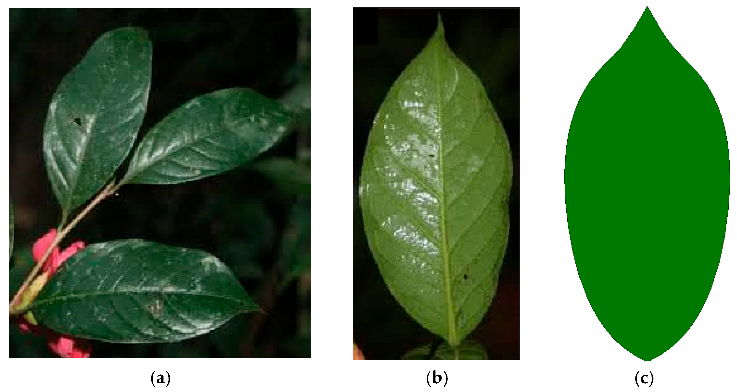
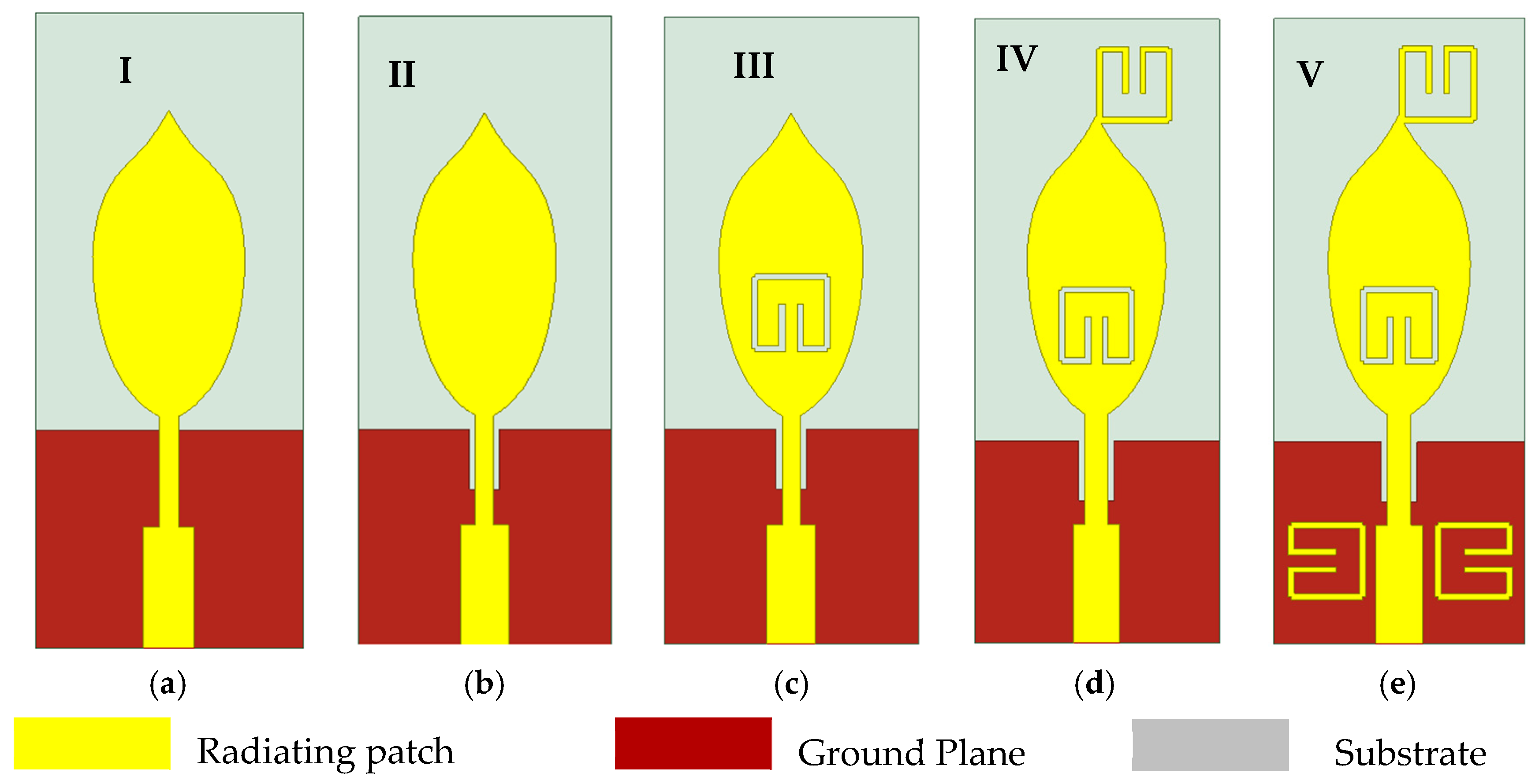
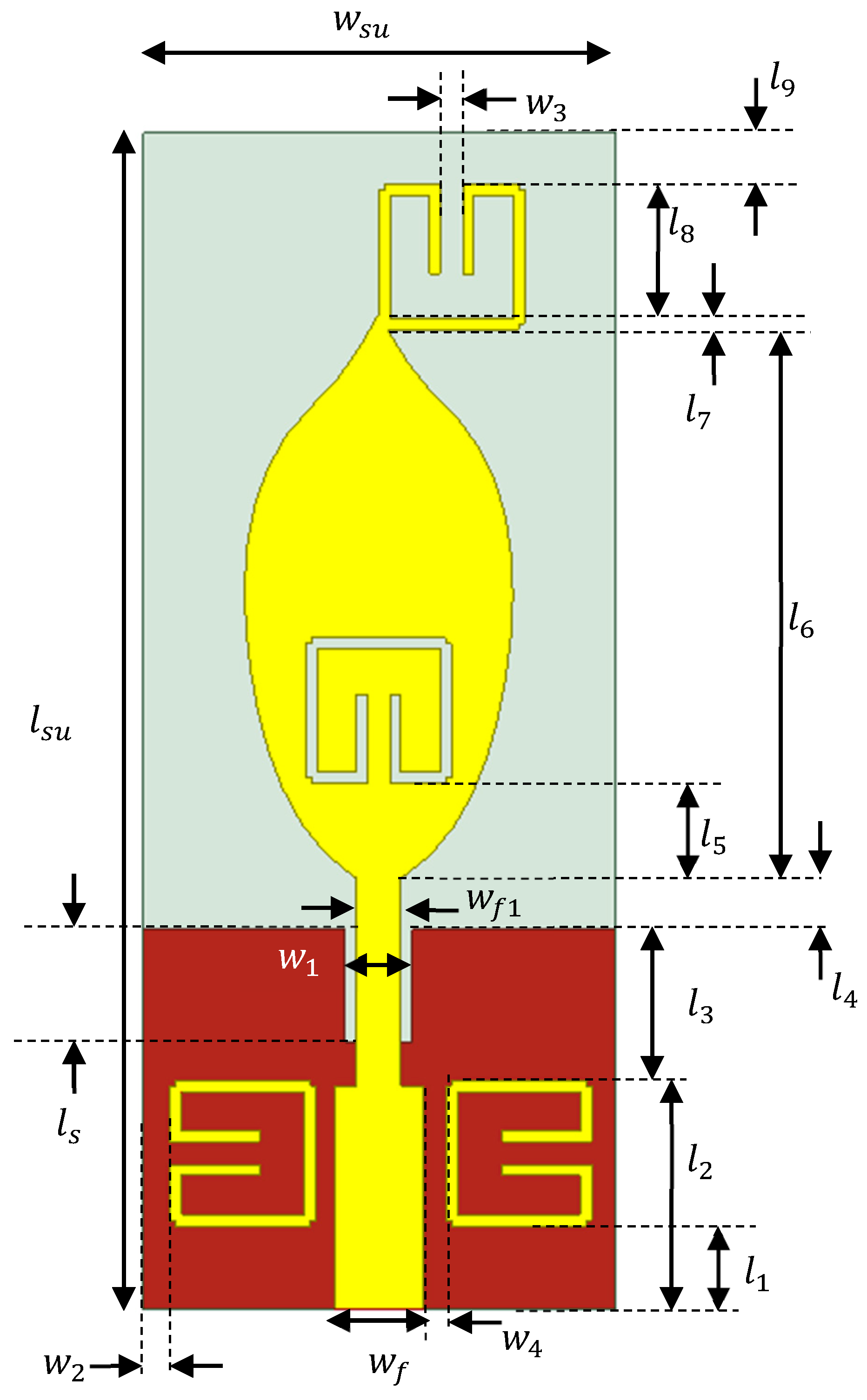
A typical Viburnum tinus (VT) array and a single leaf are as shown in Figure 1a and Figure 1b, respectively. The ovate geometry of the Viburnum tinus leaf provides a moderate aspect ratio, which enables an optimal trade-off between compactness and performance. This configuration supports the wideband operation, better radiation efficiency, and simultaneously mitigates surface wave losses [37,38]. The leaf shape is modeled as shown in Figure 1c and is used as the radiating patch of the proposed antenna. The design of the proposed antenna consists of five stages, as shown in Figure 2. In stage I, the modeled Viburnum tinus leaf shape is fed with a stepped feed on a duroid 5880 substrate backed with a partial ground plane, as shown in Figure 2a. In order to improve the impedance matching, a rectangular slit is incorporated on the ground plane to form a defected ground surface (DGS) as shown in Figure 2b (stage II). A notch was introduced by incorporating a folded ring slot on the radiating patch of the proposed antenna, as shown in Figure 2c (stage III). In order to broaden the bandwidth of the proposed antenna, a folded ring is integrated in the radiating patch to increase the surface area of the Viburnum tinus leaf-shaped antenna and thereby create another resonance to improve the bandwidth, as shown in Figure 2d (stage IV). Finally, to improve the impedance matching of the antenna at the lower band, two folded rings were used around the feedline as the parasitic elements, as shown in Figure 2e (stage V). The dimensions of the VT-shaped antenna are parameterized as shown in Figure 3, and the parametric values are presented in Table 1.
According to authors in [39,40], the fundamental resonant frequency of an arbitrarily shaped microstrip patch antenna can be predicted using Equations (1)–(3), where A eff  is the radiating patch effective area; A p is the physical radiating patch area; ε reff   is the substrate’s effective permittivity, and h is substrate thickness. The area of the modeled Viburnum tinus leaf shape is 0.021 mm2, and the thickness of the substrate used is 25 µm. Therefore, a fundamental resonant frequency according to Equations (1)–(3) is 0.22 THz.
f r m n 0 X m n c 2 A e f f h ε r e f f
A eff A p 1 + 2 h 2 π A p ln A p 2 h 2 + 1.41 ε + 1.77 + h 2 A p 0.268 ε r + 1.65 1 2  
ε reff   ε r + 1 2
The proposed antenna is designed and simulated using the high frequency simulation software (HFSS 19.0) by Ansys®. The results of the HFSS simulation are presented in the next section.

3. Results and Discussion

3.1. Reflection Coefficient

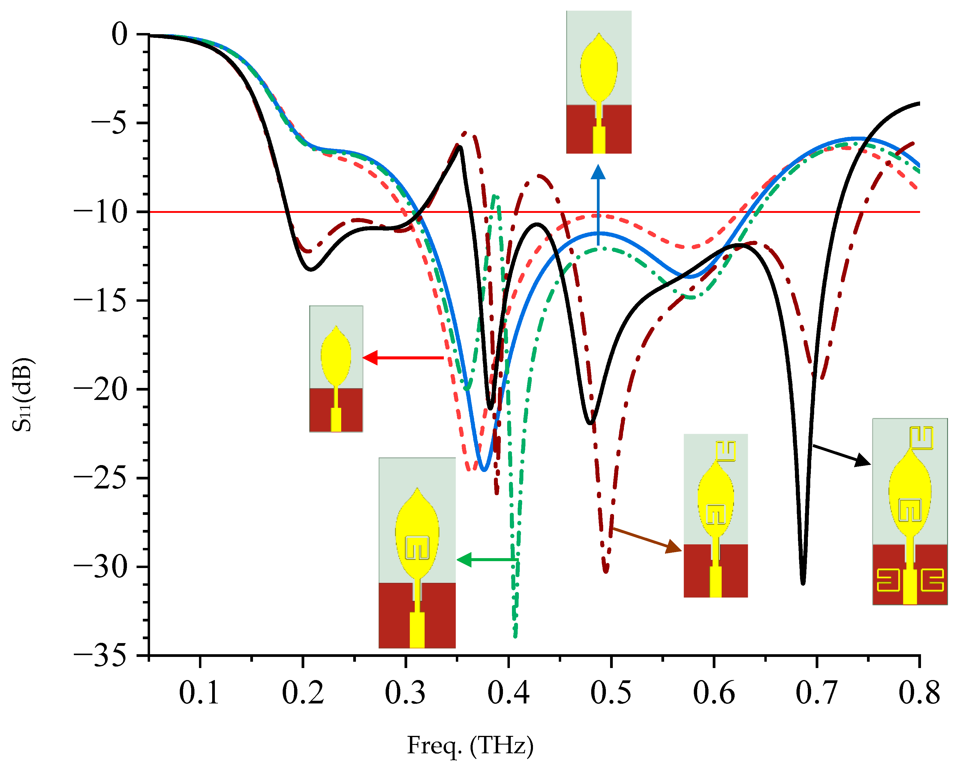
Figure 4 shows the reflection coefficient S11 of the five stages of the design algorithm. It can be observed that at stage I, the antenna shows the first resonance at 0.22 THz with an S11 of −6.6 dB. The second and third resonances are at 0.36 THz and 0.58 THz, respectively, and form a wideband with a −10 dB bandwidth of 326.21 GHz (298.25–624.46 GHz), as shown in Figure 4. It is observed that the first resonance is a parameter in correlation with the predicted fundamental resonant frequency in Section 2 which further validates the model equations.
It can be observed that when the ground plane is defected by using a slit under the feedline (stage II), the reflection coefficient is further improved with a little shift in the resonant frequencies. The essence of the defected ground surface (DGS) is to improve the impedance matching of the antenna, as shown in Figure 4. When a folded slot is etched on the radiating patch (III), a notch was observed at 0.39 THz with the −10 dB bandwidth of 334.75 GHz (307.49–642.24 GHz). It can be observed that with the incorporation of the slot, four resonances occurred at 0.22 THz, 0.36 THz, 0.4 THz, and 0.58 THz with S11 of −6.6 dB, −20 dB, −34 dB, and −15 dB, respectively, as shown in Figure 4.
The incorporation of the folded ring as part of the radiating patch results in a 67.02% increase in bandwidth with two band notches at 0.36 THz (318.17–377.59 GHz) and 0.43 THz (407.41–451.67 GHz), as shown in Figure 4. It can be observed in Figure 4 that, with the introduction of two parasitic folded rings at the feedline (stage V), the impedance matching of the proposed antenna improves particularly at the lower band and removes the second notch band introduced by the folded ring incorporated in stage IV.

3.2. Radiation Patterns, Surface Current Distribution, Gain, and Efficiency

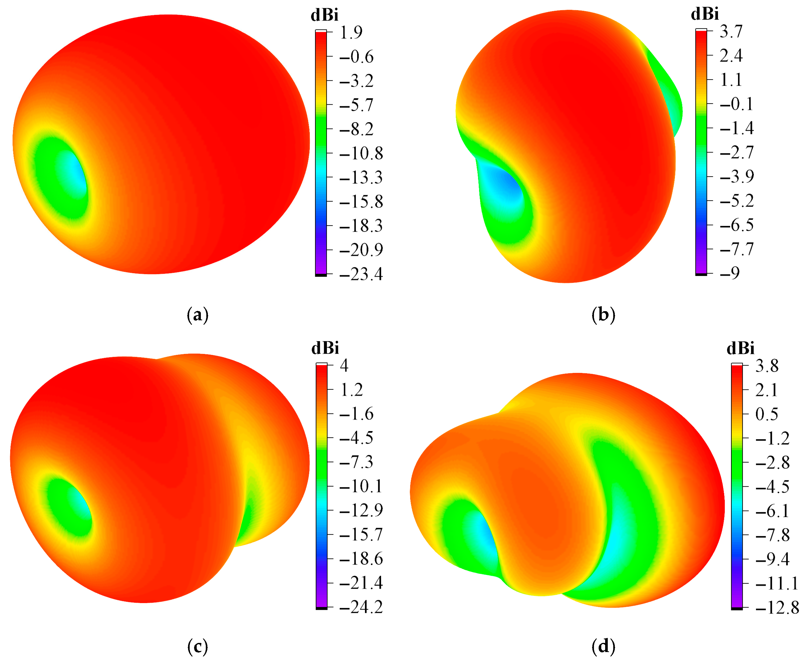
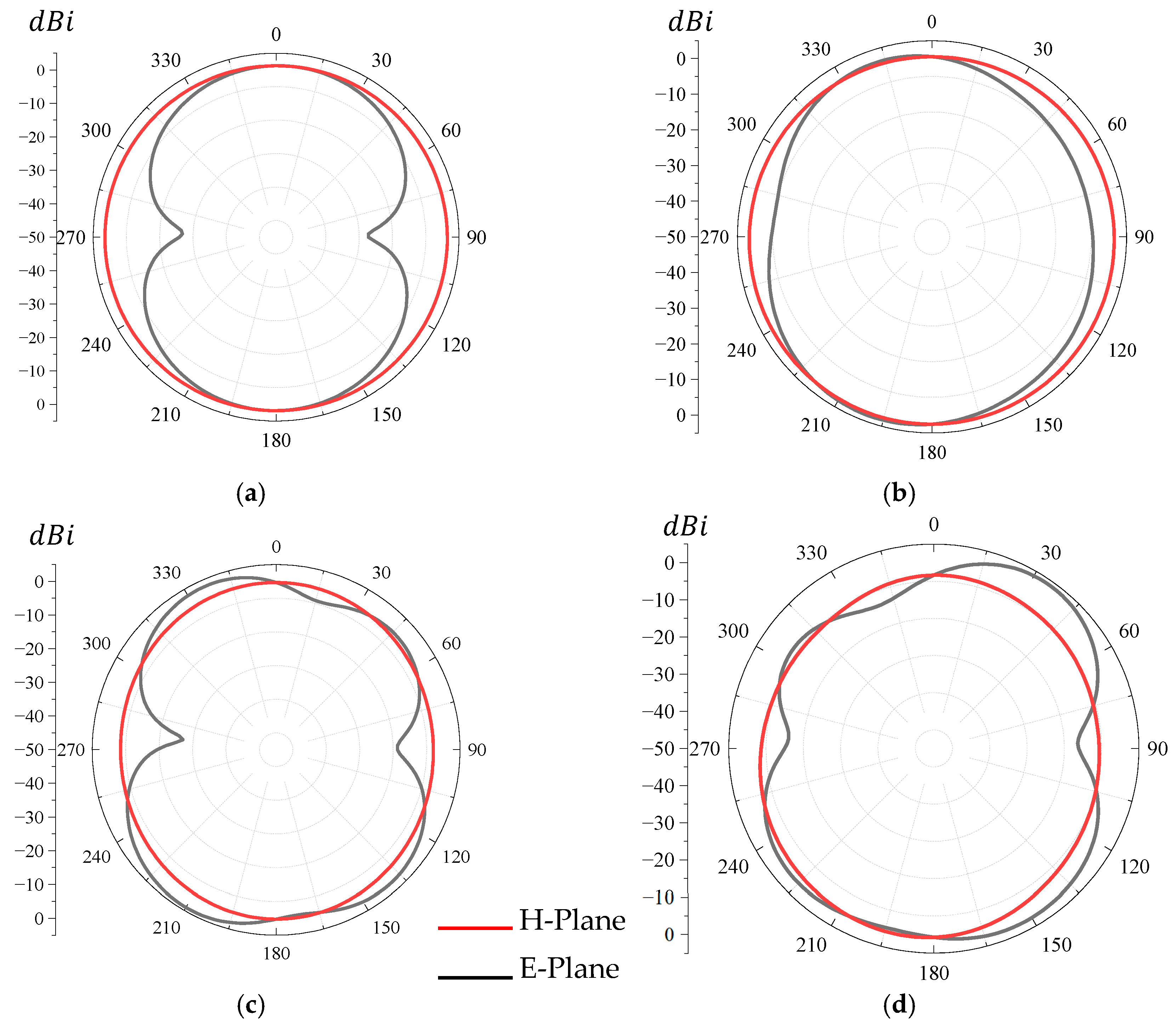
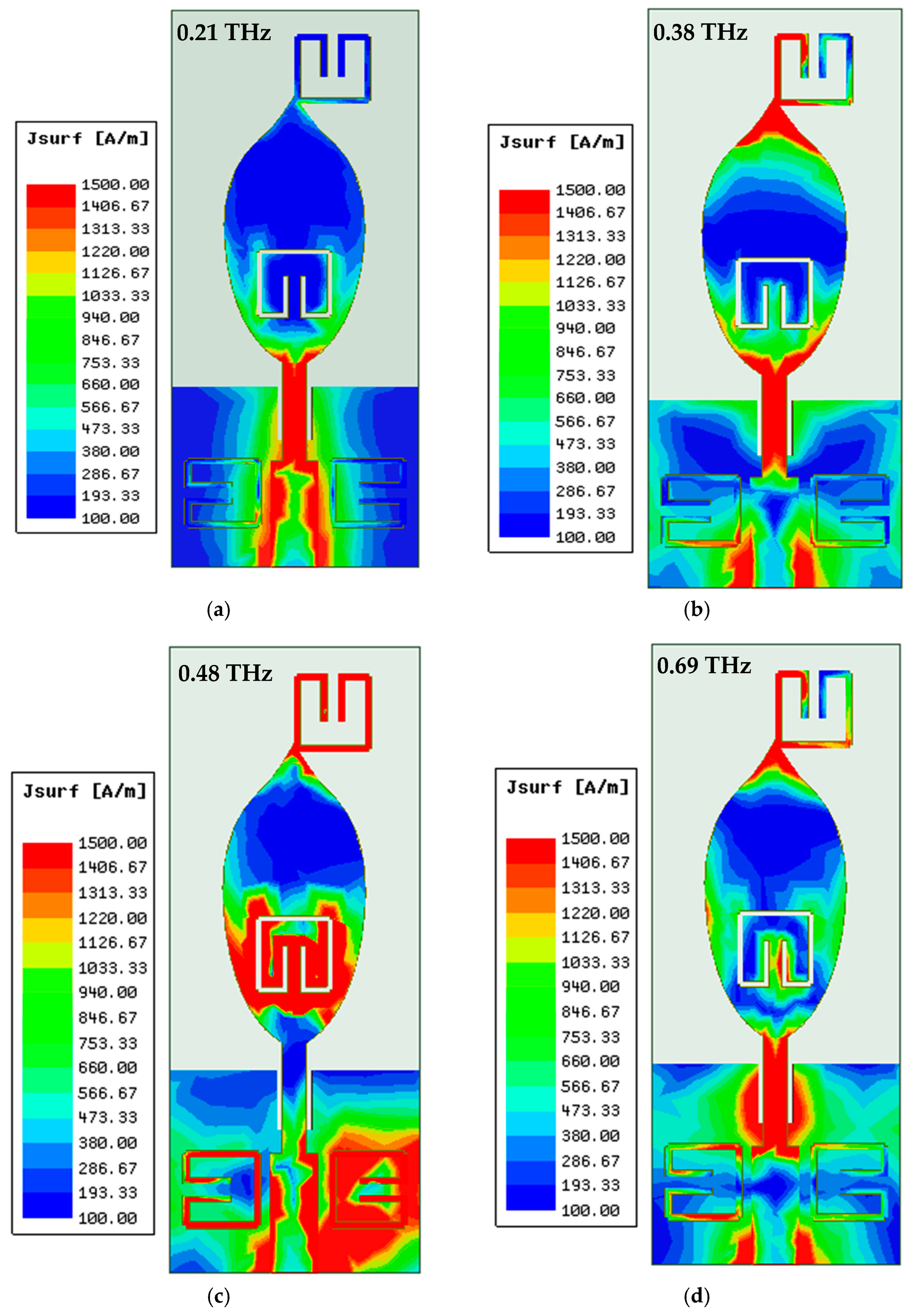
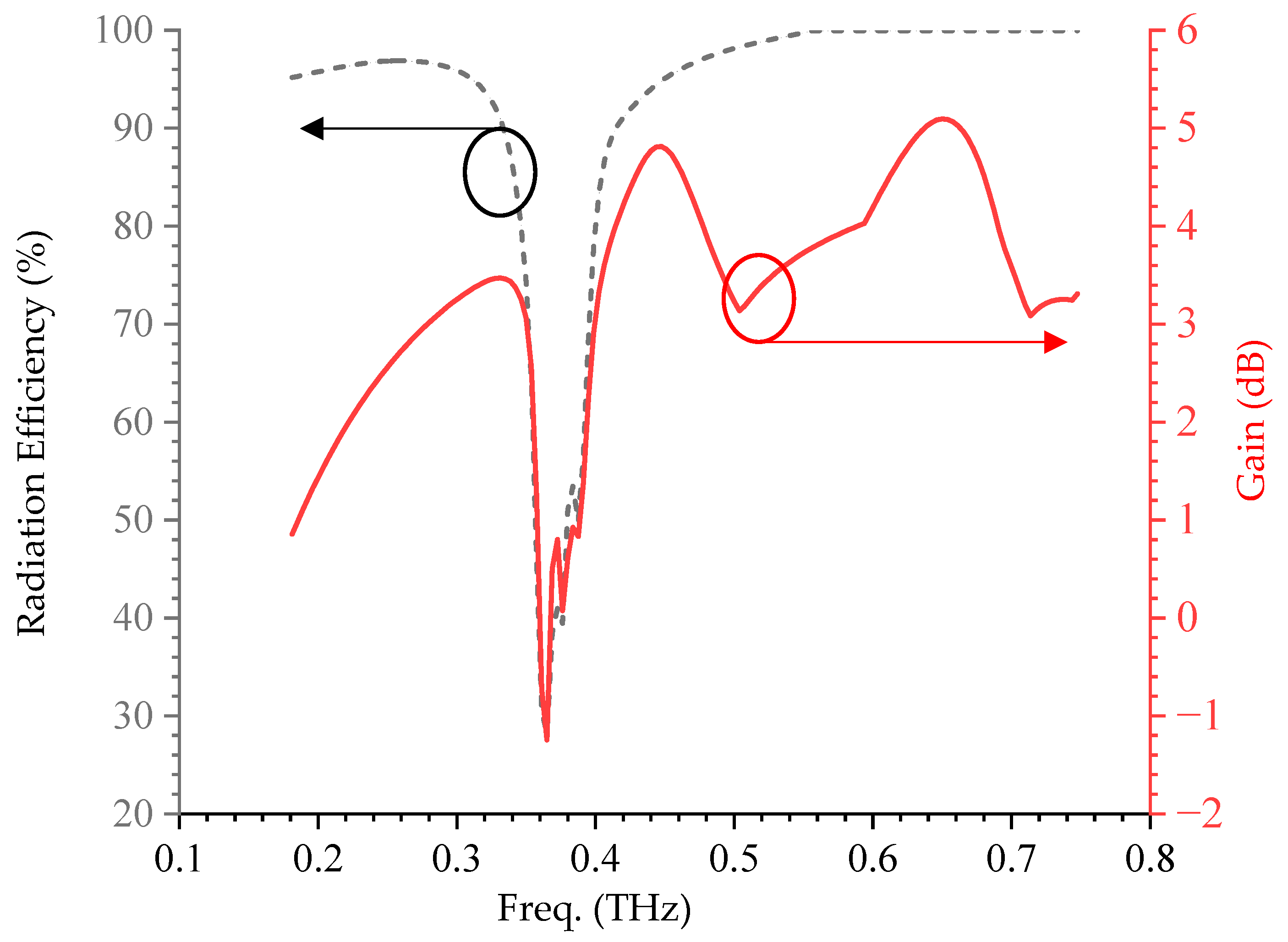
The 3D radiation patterns, the E-plane and H-plane radiation patterns at the resonant frequencies, surface current distribution, and radiation efficiency and gain plots are presented in Figure 5, Figure 6, Figure 7 and Figure 8, respectively. The peak gains at 0.21 THz, 0.38 THz, 0.48 THz, and 0.69 THz are 1.9 dBi, 3.7 dBi, 4.0 dBi, and 3.8 dBi, respectively, as shown in Figure 5. The radiation patterns shown in Figure 6 show that the proposed VTB-A has a quasi-omnidirectional radiation pattern in the E-plane and an omnidirectional pattern in the H-plane at all the resonant frequencies.
Figure 7a shows that the major contributor for the resonance at 0.21 THz is the Viburnum tinus, with little contributions from the parasitic folded-ring and the incorporated folded-ring. This revealed the reason for the improvement noticed in the reflection response at this frequency when the folded ring was incorporated into the design. The concentration of the highest surface current along the feedline and the base of the radiating patch shows that there is a strong coupling between the input port and the radiating patch, which leads to good radiation efficiency. The resonance observed at 0.38 THz is majorly affected by the periphery of the VT, the incorporated folded ring, and the parasitic folded ring, as can be seen in Figure 7b. At this frequency, the surface current distribution reveals the excitation of higher-order modes, with stronger concentration along the patch edges and parasitic folded rings. This interaction enhances capacitive–inductive coupling, which broadens the bandwidth and improves the radiation efficiency. It can be observed from Figure 7c that the folded ring, the Viburnum tinus leaves around the folded-ring slot, and the parasitic folded ring contributed to the resonance at 0.48 THz. It can also be observed that the dominant currents are localized within the parasitic folded rings and central patch region, producing extended current loops that enhance the reactive loading and mode hybridization. Resonance at 0.69 THz is the combinatory effect of the slot, the incorporated folded ring and the ground plane slot, as observed in Figure 7d.
The radiation efficiency of the VTB-A is presented in Figure 8. It can be observed that the proposed antenna has good radiation efficiency across the operating band except at the notch band, which shows that the antenna will not radiate/receive a signal at this frequency. A 25% radiation efficiency is observed at the notch frequency, as seen in Figure 8. It can also be observed that VTB-A has suitable gain across the entire operating bandwidth with a peak gain of 5 dBi, except at the notch frequency where the gain is negative, as seen in Figure 8. A negative gain at the notched frequency means that transmission/reception at this frequency would be attenuated and thereby prevented.

4. Validation of the Proposed VTB-A Antenna

The proposed VTB-A is validated through the equivalent circuit model and a finite difference time domain simulator, CST microwave studio, and the results are presented in this section. The equivalent circuit lump parameters are predicted using Equations (4)–(6) [21,22], modeled, and simulated in AWR studio. The purpose of the equivalent circuit is to provide a simplified electrical model to enable a more practical and effective design and analysis of the proposed antenna. Figure 9 shows the schematic diagram of the equivalent circuit (EC) modeled in AWR, and the value of each lumped element parameter is presented in Table 2. The feedline is modeled as a transmission line segment with a characteristic impedance, ensuring impedance matching to the source. The radiating patch corresponds to a parallel R L C resonator, where the inductance L represents the current path along the radiating patch, the capacitance C arises from the fringing fields between the patch edges and ground plane, and the resistance R models the radiation and conductor losses. It can be observed from Figure 4 that the initiator radiating patch excites three resonances, which implies three (3) series parallel RLC circuits. The embedded slot within the patch introduces additional parallel RLC tanks, with the slot length defining inductive behavior due to the circulating currents, while the slot gap provides capacitive coupling. Similarly, the parasitic folded rings are represented by coupled RLC resonators, where inductance accounts for the extended current loops and capacitance corresponds to the narrow gaps between adjacent ring arms, making seven parallel RLC resonators as shown in Figure 9.
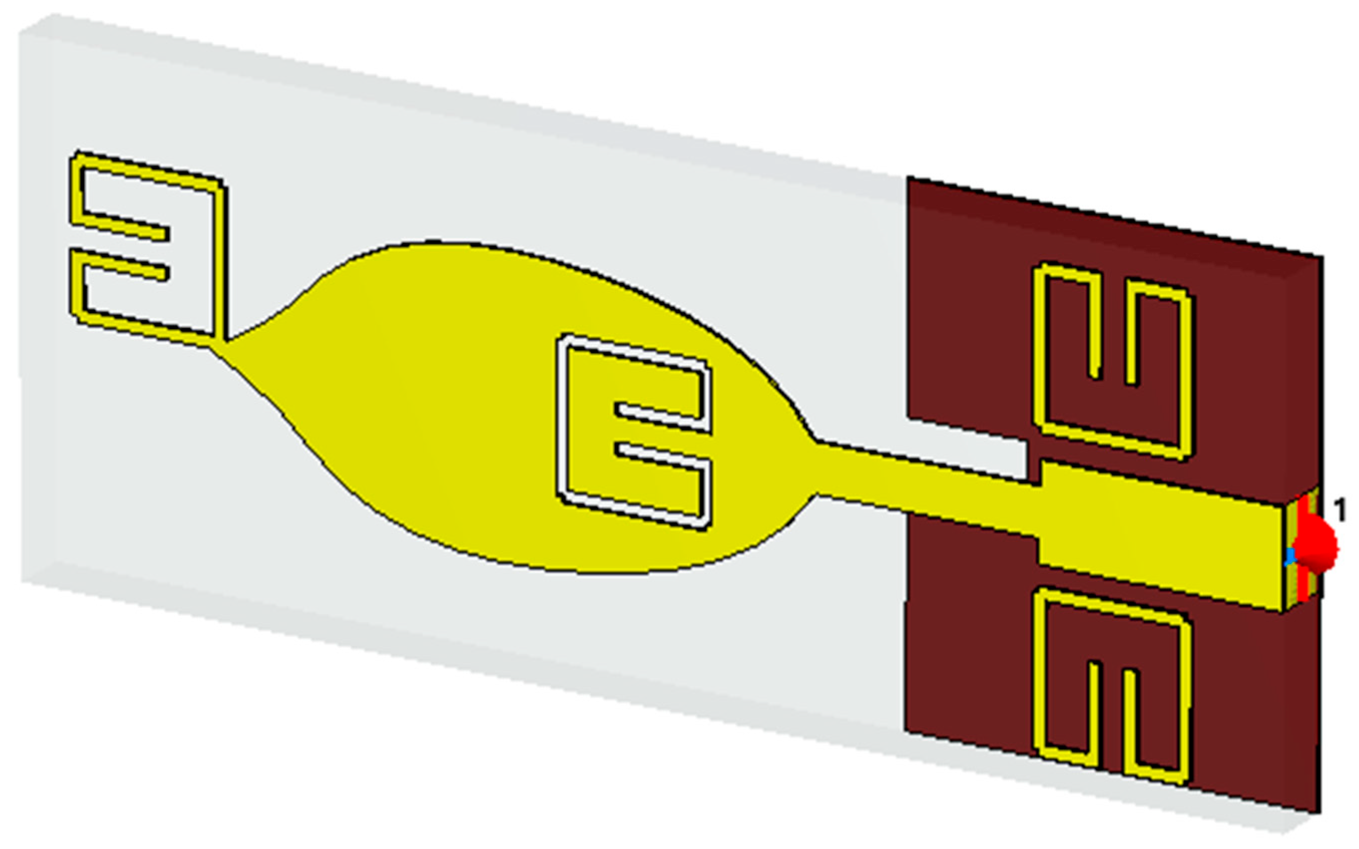
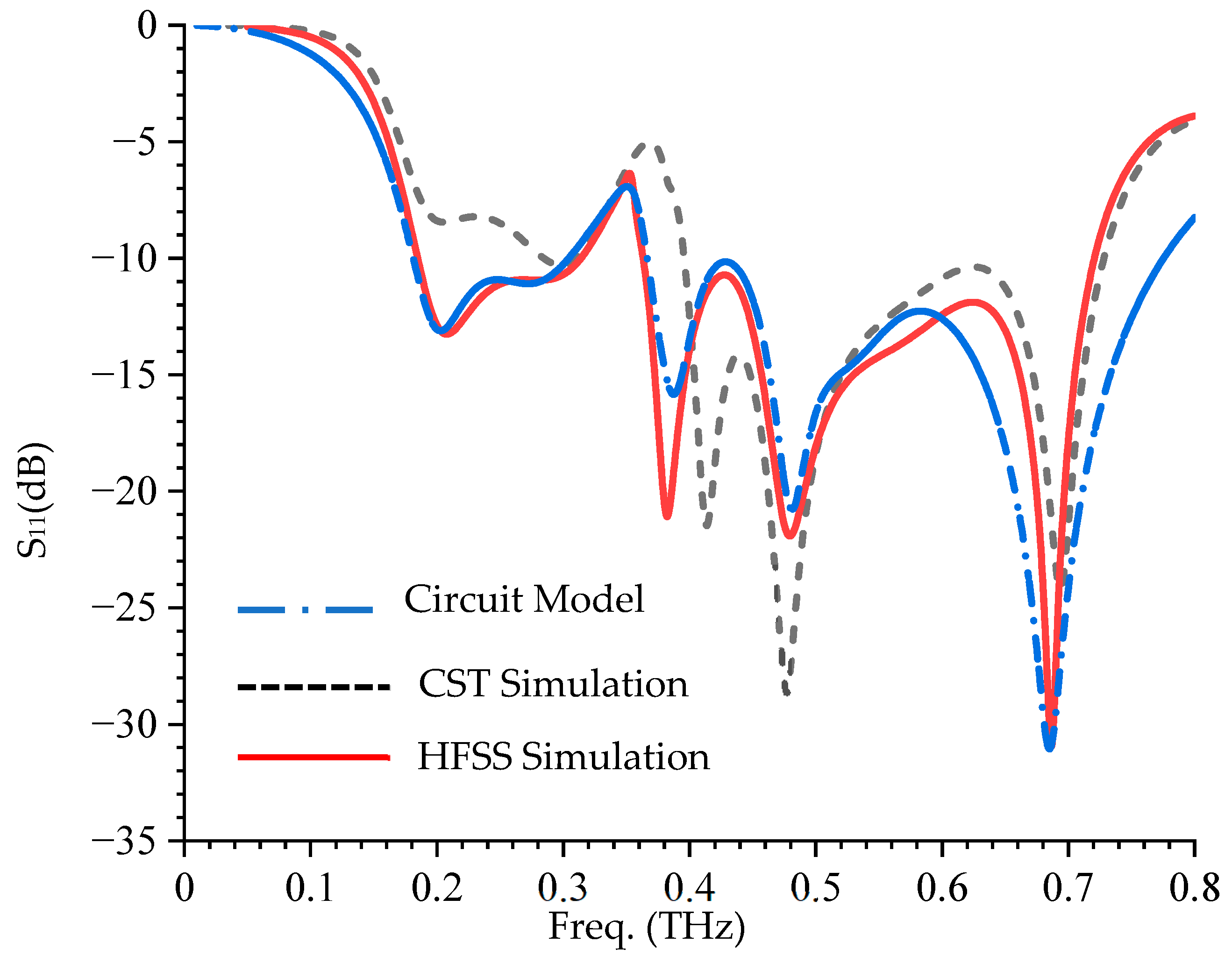
Also, the proposed antenna is simulated in the CST microwave studio, as shown in Figure 10. The reflection coefficient responses of the equivalent circuit (EC) and CST microwave studio simulations with the HFSS simulation are presented in Figure 11. There is a good agreement in the reflection coefficient response of EC and HFSS, as observed in Figure 11. Although there is a little discrepancy between the HFSS and CST reflection coefficient responses at the lower band, it can be observed that they follow the same pattern. This is because HFSS is based upon the finite element method, which is known to be more accurate than the CST-FDTD method [24]. Notwithstanding, there is a reasonable consistency in S11 of HFSS, CST, and EC, as shown in Figure 11.
C = w c 2 Z o w o 2 w c 2
L = 1 w o 2 C  
R = 2 Z o 1 / S 11 w o 2 2 Z o w o C 1 / w o L 2 1

5. Parametric Analysis

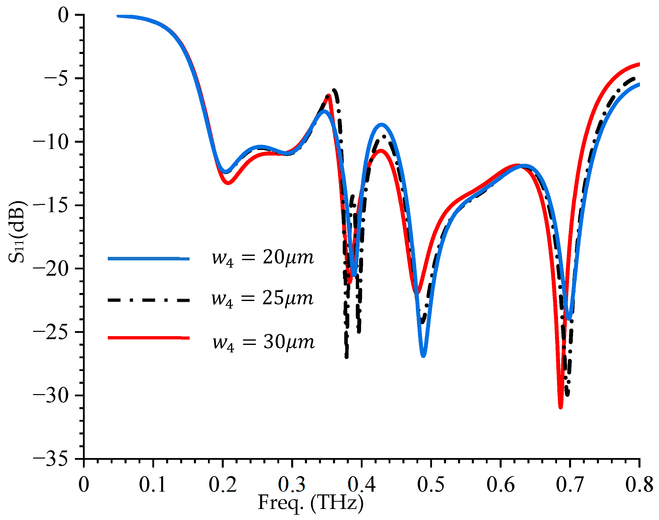
5.1. Effect of Parasitic Feedline Gap ( w 4 ) on S11

Figure 12 shows the S11 response of VTB-A as the space between the parasitic folded ring and the feedline changes. It can be observed that as the space increases, S11 at the lower band decreases but with a corresponding deterioration at the two middle resonances, as seen in Figure 12. It is worth noting that at the uppermost resonant frequency, as the gap increases, the S11 keeps increasing with a little downward shift, as shown in Figure 12. This effect is due to the formation of the capacitive-inductance ( L C ) by the folded-ring loading with the proposed antenna structure through the gap ( w 4 ) . So, a change in w 4 leads to a change in the capacitance and therefore a change in the resonance nature of the structure. Hence, 30   μ m is choosen as the optimized value.

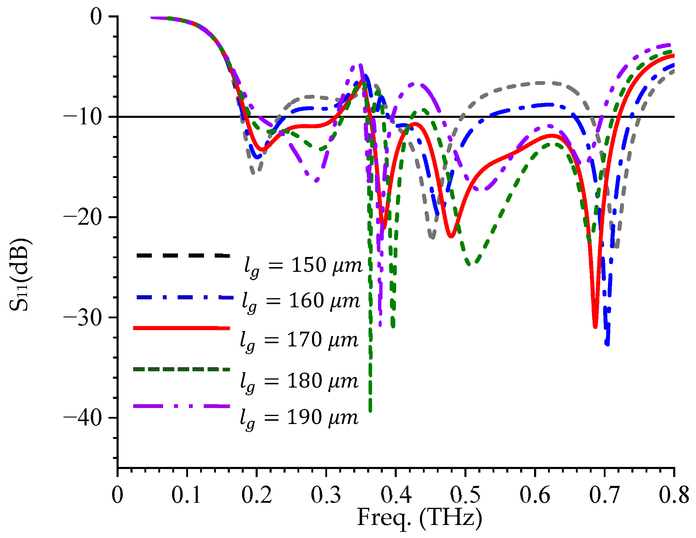
5.2. Effect of the Ground Plane Length on S11  ( l g = l 2 + l 3 )

The effect of the ground plane on S11 is presented in Figure 13. It can be seen that the ground plane has a significant effect on the reflection response of the proposed antenna. For instance, at the first resonant frequency, it can be observed that as l g increases, S11 increases, whereas the same changes cause a decrease in S11 at the second resonant frequency. It can also be noted that at the third resonant frequency, an increase in l g results in good impedance matching at this frequency, as seen in Figure 13. Its effect on the fourth resonant frequency is a significant shift in the resonant frequency and it can also be observed that at the uppermost resonant frequency, S11 decreases with the increase in l g  until l g = 160   μ m and starts to deteriorate as l g continue to increase.

5.3. Effect of the Ground Slit Length ( l s )  on S11

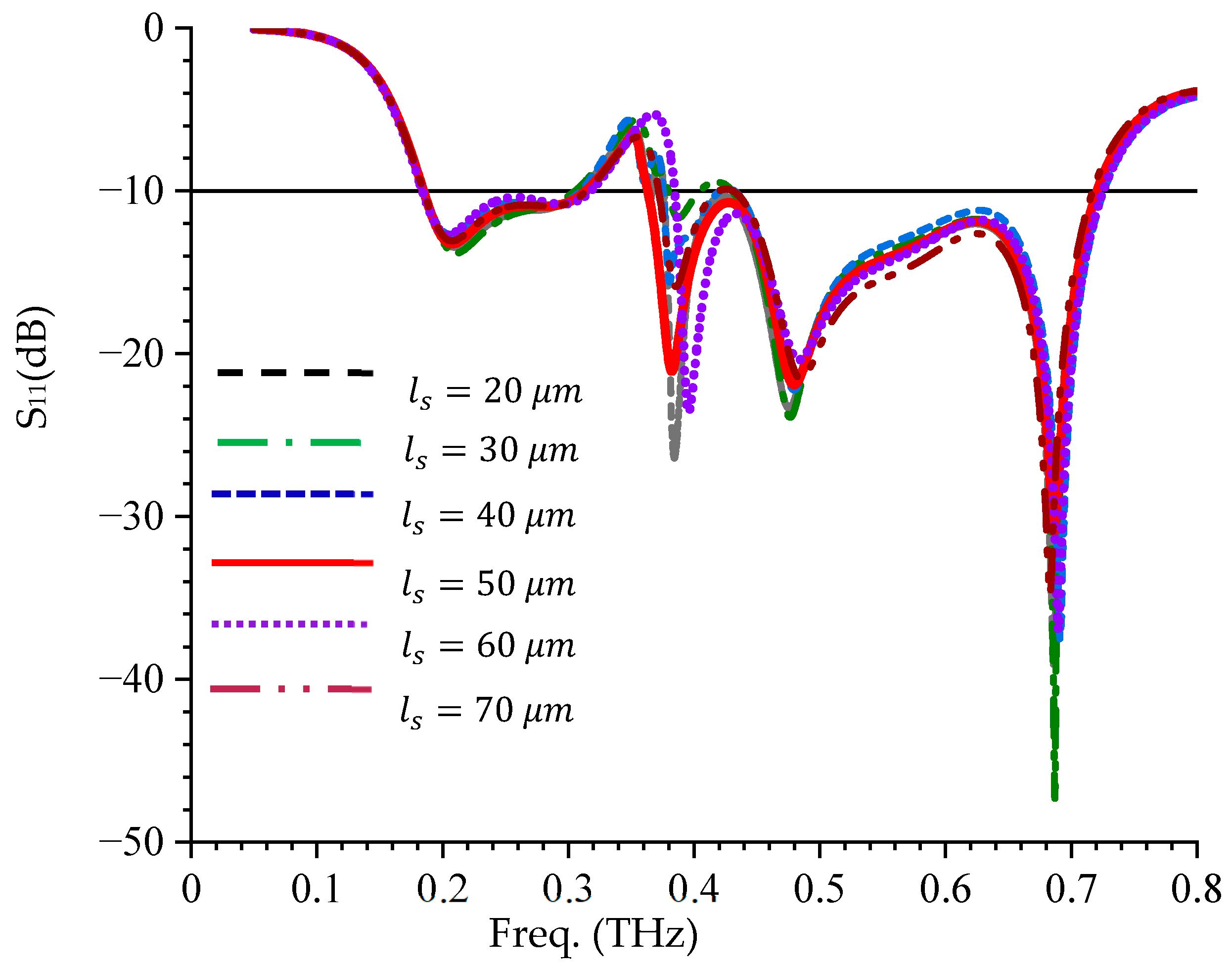
The S11 response for different values of l s is presented in Figure 14. It can be observed that the change in l s does not have any significant effect on S11 at the first, second, and fourth resonant frequencies, but a significant effect is noticed at the third and the fifth resonant frequencies. For instance, when l s changed from 20   μ m to 30   μ m , a significant deterioration in S11 is observed at the third resonant frequency, but as it continues to increase, it begins to improve until l s  is   60   μ m any further increase from that point leads to a deterioration again, as seen in Figure 14.

5.4. Effect of the Ground Slit Width ( w 1 ) on S11

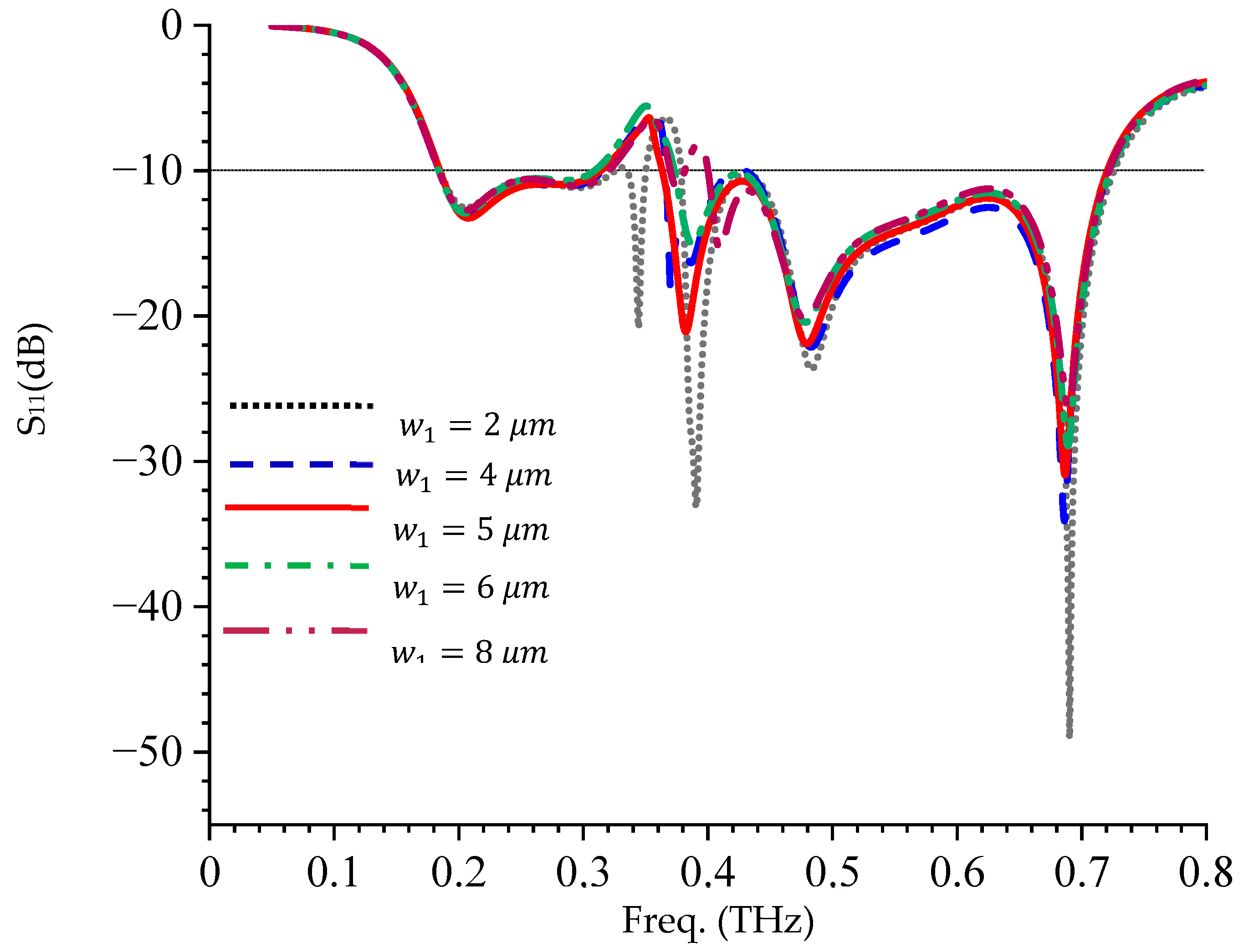
Figure 15 shows the S11 response of the proposed antenna with the variation of w 1 . It can be observed that w 1 only has significant effect on the third and fifth resonant frequencies. The effect is noticed only on the S11 at the fifth resonant frequency, but on both S11 and the resonant frequency at the third, as seen in Figure 15.

5.5. Effect of the Space Between the Folded Ring Slot and Feedline ( l 5 )

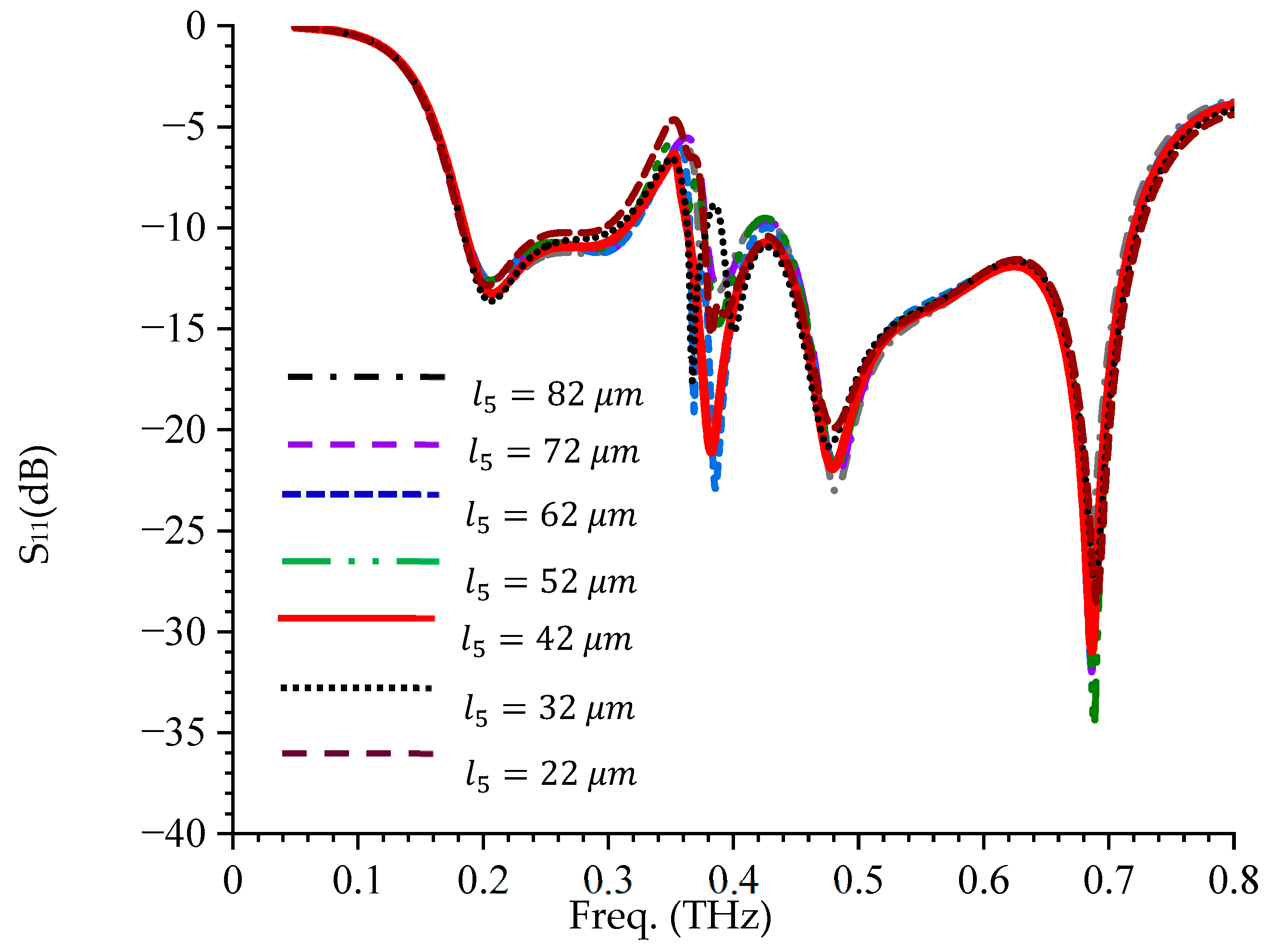
Figure 16 shows the effect of l 5 on S11 response of the proposed antenna. It can be observed that l 5 only has significant effect on the third resonant frequency. This is because of the third resonance is majorly contributed by the surface of the radiating patch below the folded ring slot, as shown by the surface current distribution. Therefore, any change in that space will result in the change in resonance at that frequency, as seen in Figure 16.

6. Comparative Analysis

The comparative study of the proposed VTB-A with the antennas reported in [10,20,41,42,43,44,45,46,47,48,49] was carried out and reported in Table 3. Guided wavelength size is used in this work to capture the effect of the permittivity on the size of the antenna. As can be observed in Table 3, in terms of size, the footprint of the proposed VTB-A is smaller compared with the recently published works in the literature. In the case of impedance bandwidth, the proposed VTB-A antenna shows superiority when compared with the existing work, despite its compactness, as seen in Table 3. In terms of gain, it can be observed that the gain of the proposed VTB-A is higher than the gain of the antenna proposed by authors in [43,44,45]. Although antennas reported in [20,41,42,46,47] have better gain than VTB-A, but these antennas are larger as compared to the proposed antenna. In terms of radiation efficiency, the proposed VTB-A outperforms the recently published work despite its compactness, as observed in Table 3. As shown in Table 3, authors in [48,49] proposed a notch band terahertz antenna but with a much higher footprint than the VTB-A proposed in this work. For instance, the antenna in [48] has a higher gain than the VTB-A but with a lesser radiation efficiency and bigger footprint. Likewise, the antenna presented in [49] has a wider bandwidth but a lesser gain and radiation efficiency compared with the proposed VTB-A. Based on the foregoing, VTB-A has a highly competitive edge compared with the most recent works in the existing literature and therefore stands out for terahertz applications in the future wireless communication and terahertz imaging.

7. Conclusions

A novel ultracompact Viburnum tinus leaf-based bio-inspired wideband antenna (VTB-A) has been presented in this work. The impedance bandwidth of 0.18–0.72 THz (536 GHz bandwidth), peak gain of 5 dB, and radiation efficiency of 99.8% were achieved despite its compactness with the dimensions of 0.46 λ g × 0.18 λ g . A band notch at 0.39 THz was achieved through the use of a folded-ring slot on the radiating patch. The proposed VTB-A is validated through FDTD and equivalent circuit modeling, and the results show good agreement. The comparative analysis shows that VTB-A has a highly competitive edge compared to the recent works in the existing literature in terms of size, bandwidth, gain, efficiency, and band-notching and therefore stand out for terahertz applications in the future wireless communication (beyond 5G and 6G) and terahertz imaging. In the future, terahertz metamaterial will be developed and incorporated to further improve the gain of the proposed antenna (VTB-A), and deployed in a MIMO scenario for terahertz channel diversity.

Author Contributions

Conceptualization, J.O.A., D.B.O.K., P.K. and G.O.; methodology, D.B.O.K., P.K. and G.O.; software, J.O.A.; formal analysis, J.O.A.; writing—original draft, J.O.A.; writing—review and editing, D.B.O.K., P.K. and G.O. All authors have read and agreed to the published version of the manuscript.

Funding

This research received no external funding.

Data Availability Statement

The original contributions presented in this study are included in the article. Further inquiries can be directed to the corresponding author.

Conflicts of Interest

The authors declare no conflict of interest.

References

  1. Azam, F.; Shah, S.I.H.; Bashir, S.; Koziel, S. Review of recent advancement on nature/bio-inspired antenna designs. IEEE Access 2024, 12, 37493–37512. [Google Scholar] [CrossRef]
  2. Raghunath, J.; Kumar, P.; Ali, T.; Kumar, P.; Shariff Bhadrvathi Ghouse, P.; Pathan, S. A quad-port nature-inspired Lotus-shaped wideband terahertz antenna for wireless applications. J. Sens. Actuator Networks 2023, 12, 69. [Google Scholar] [CrossRef]
  3. Petrov, V.; Pyattaev, A.; Moltchanov, D.; Koucheryavy, Y. Terahertz band communications: Applications, research challenges, and standardization activities. In Proceedings of the 2016 8th International Congress on Ultra Modern Telecommunications and Control Systems and Workshops (ICUMT), Lisbon, Portugal, 18–20 October 2016; pp. 183–190. [Google Scholar] [CrossRef]
  4. Chen, Z.; Han, C.; Yu, X.; Wang, G.; Yang, N.; Peng, M. Terahertz wireless communications. China Commun. 2021, 18, 3–7. [Google Scholar] [CrossRef]
  5. Abolade, J.O. Miniaturized multiband antenna for terahertz applications in wireless body area network. Results Opt. 2023, 10, 100340. [Google Scholar] [CrossRef]
  6. Keshwala, U.; Rawat, S.; Ray, K. Design and analysis of DNA shaped antenna for terahertz and sub-terahertz applications. Optik 2021, 232, 166512. [Google Scholar] [CrossRef]
  7. Khajawal, T.; Rubani, Q.; Rajawat, A.; Gupta, S.H. Performance analysis and optimization of band gap of terahertz antenna for WBAN applications. Optik 2021, 243, 167387. [Google Scholar] [CrossRef]
  8. Davoudabadifarahani, H.; Ghalamkari, B. High efficiency miniaturized microstrip patch antenna for wideband terahertz communications applications. Optik 2019, 194, 163118. [Google Scholar] [CrossRef]
  9. Singhal, S. Asymmetrically CPW fed square Sierpinski Carpet ultra wideband terahertz antenna. Optik 2021, 242, 167056. [Google Scholar] [CrossRef]
  10. Shalini, M.; Madhan, M.G. A compact antenna structure for circular polarized terahertz radiation. Optik 2021, 231, 166393. [Google Scholar] [CrossRef]
  11. Naik, K.K.; Suman, M.; Rao, E.V.K. Design of complementary split ring resonators on elliptical patch antenna with enhanced gain for terahertz applications. Optik 2021, 243, 167434. [Google Scholar] [CrossRef]
  12. Rubani, Q.; Gupta, S.H.; Rajawat, A. A compact MIMO antenna for WBAN operating at Terahertz frequency. Opt. Int. J. Light Electron Opt. 2020, 207, 164447. [Google Scholar] [CrossRef]
  13. Zhang, X.; Fu, H.; Ma, K.; Yan, N.; Liu, Y.; Mu, Y. Investigation of channel parasitic effect of CMOS transistor for high responsivity 2.58 THz detector array with patch antennas in chip. IEEE Trans. Terahertz Sci. Technol. 2023, 13, 464–475. [Google Scholar] [CrossRef]
  14. Ashyap, A.Y.I.; Inam, M.; Kamarudin, M.R.; Dahri, M.H.; Shamsan, Z.A.; Almuhanna, K.; Alorifi, F. Multi-band metamaterial antenna for terahertz applications. Comput. Mater. Contin. 2023, 74, 1765–1782. [Google Scholar] [CrossRef]
  15. Abolade, J.O. Tri-band bio-inspired terahertz antenna with integrated negative-refractive-index metamaterial for terahertz applications. Next Res. 2024, 1, 100067. [Google Scholar] [CrossRef]
  16. Vishwanath; Varshney, G.; Sahana, B.C. Design of tunable THz dielectric resonator antenna with cross-slot for circular polarization. Opt. Quantum Electron. 2024, 56, 922. [Google Scholar] [CrossRef]
  17. Fakhte, S.; Taskhiri, M.M. Dual-band terahertz dielectric resonator antenna with graphene loading. Opt. Quantum Electron. 2022, 54, 845. [Google Scholar] [CrossRef]
  18. Yadav, R.; Judice, A.; Pandey, V.S. Dual-substrate graphene THz antenna design for advanced sensing applications. J. Opt. 2024, 2024, 1–11. [Google Scholar] [CrossRef]
  19. Kumar, C.; Raghuwanshi, S.K.; Kumar, V. Graphene-based patch antenna array on photonic crystal substrate at terahertz frequency band. J. Electromagn. Waves Appl. 2024, 38, 250–263. [Google Scholar] [CrossRef]
  20. Kiani, N.; Hamedani, F.T.; Rezaei, P. Polarization controlling plan in graphene-based reconfigurable microstrip patch antenna. Optik 2021, 244, 167595. [Google Scholar] [CrossRef]
  21. Tiwari, R.N.; Kumar, P.; Singh, G. 2-D photonic crystals as substrate for THz/millimeter wave microstrip patch antennas. In Proceedings of the 2008 International Conference of Recent Advances in Microwave Theory and Applications, Jaipur, India, 21–24 November 2008; pp. 787–789. [Google Scholar]
  22. Nissan, U.N.; Singh, G.; Ayokunle, A. Low sidelobe levels Terahertz microstrip antennas for bio-sensing and communications. Sens. Int. 2021, 2, 100097. [Google Scholar] [CrossRef]
  23. Costantine, J.; Tawk, Y.; Christodoulou, C.G.; Mosbeh, Z. Handbook of Antenna Technologies; Springer International Publishing: Cham, Switzerland, 2014; pp. 1–30. [Google Scholar] [CrossRef]
  24. Jamshed, M.A.; Nauman, A.; Abbasi, M.A.B.; Kim, S.W. Antenna Selection and Designing for THz Applications: Suitability and Performance Evaluation: A Survey. IEEE Access 2020, 8, 113246–113261. [Google Scholar] [CrossRef]
  25. Ghimire, J.; Choi, D.Y. Design of a compact ultrawideband U-shaped slot etched on a circular patch antenna with notch band characteristics for ultrawideband applications. Int. J. Antennas Propag. 2019, 2019, 1–10. [Google Scholar] [CrossRef]
  26. Yadav, A.; Singh, V.K.; Bhoi, A.K.; Marques, G.; Garcia-Zapirain, B.; de la Torre Díez, I. Wireless body area networks: UWB wearable textile antenna for telemedicine and mobile health systems. Micromachines 2020, 11, 558. [Google Scholar] [CrossRef]
  27. Babu, P.R.; Ramakrishna, D.; Ensermu, G. Triple Band-Notch UWB Antenna Embedded with Slot and EBG Structures. Wirel. Commun. Mob. Comput. 2023, 2023, 3461751. [Google Scholar] [CrossRef]
  28. Chen, X.; Xu, F.; Tan, X. Design of a compact UWB antenna with triple notched bands using nonuniform width slots. J. Sensors 2017, 2017, 7673168. [Google Scholar] [CrossRef]
  29. Zebiri, C.; Sayad, D.; Elfergani, I.; Iqbal, A.; Mshwat, W.F.A.; Kosha, J.; Rodriguez, J.; Abd-Alhameed, R. A compact semi-circular and arc-shaped slot antenna for heterogeneous RF front-ends. Electronics 2019, 8, 1123. [Google Scholar] [CrossRef]
  30. Madhav, B.T.P.; Manikanta Prasanth, A.; Prasanth, S.; Krishna, B.M.S.; Manikantha, D.; NagaSai, U.S. Analysis of defected ground structure notched monopole antenna. ARPN J. Eng. Appl. Sci. 2015, 10, 747–752. [Google Scholar]
  31. Tiwari, A.; Soni, G.K.; Yadav, D.; Yadav, S.V.; Yadav, M.V. Rectangular loaded ring shaped multiband frequency reconfigurable defected ground structure antenna for wireless communication applications. Results Eng. 2025, 25, 104339. [Google Scholar] [CrossRef]
  32. Patchala, K.; Raja Rao, Y.; Prasad, A.M. Triple band notch compact MIMO antenna with defected ground structure and split ring resonator for wideband applications. Heliyon 2020, 6, e03078. [Google Scholar] [CrossRef]
  33. Biswas, A.K.; Biswas, S.; Haldar, S.; Nandi, A. A highly decoupled flexible 4-element MIMO antenna with band notched characteristics for ultra wide-band wearable applications. AEU Int. J. Electron. Commun. 2024, 173, 154985. [Google Scholar] [CrossRef]
  34. Modak, S.; Khan, T. A slotted UWB-MIMO antenna with quadruple band-notch characteristics using mushroom EBG structure. AEU Int. J. Electron. Commun. 2021, 134, 153673. [Google Scholar] [CrossRef]
  35. Abdalla, M.A.; Al-Mohamadi, A.A.; Mohamed, I.S. A miniaturized dual band EBG unit cell for UWB antennas with high selective notching. Int. J. Microw. Wirel. Technol. 2019, 11, 1035–1043. [Google Scholar] [CrossRef]
  36. Abbas, A.; Hussain, N.; Lee, J.; Park, S.G.; Kim, N. Triple rectangular notch UWB antenna using EBG and SRR. IEEE Access 2021, 9, 2508–2515. [Google Scholar] [CrossRef]
  37. Tan, S.; Zhang, L.; Sun, Q.; Tang, B.; Wang, Q. A design of a leaf-shaped biomimetic flexible wideband antenna. Electronics 2025, 14, 2620. [Google Scholar] [CrossRef]
  38. Cruz, J.D.N.; Freire, R.C.S.; De Moura, L.C.M.; Da Costa, A.P.; Da Fonseca Silva, P.H. Parametric study of printed monopole antenna bioinspired on the inga marginata leaves for UWB applications. J. Microw. Optoelectron. Electromagn. Appl. 2017, 16, 312–322. [Google Scholar] [CrossRef]
  39. Abolade, J.O.; Konditi, D.B.O.; Dharmadhikary, V.M. Corrigendum to “a comparative study of compact multiband bio-inspired asymmetric microstrip fed antennas (BioAs-MPAs) for wireless applications”. J. Eng. 2022, 2022, 6676689. [Google Scholar] [CrossRef]
  40. Abolade, J.O.; Konditi, D.B.O.; Dharmadhikary, V.M. Bio-inspired wideband antenna for wireless applications based on perturbation technique. Heliyon 2020, 6, e04282. [Google Scholar] [CrossRef]
  41. Kiani, S.; Rezaei, P.; Khajenoori, M. Wideband sun-star shape coplanar waveguide antenna for terahertz sensing applications. Results Opt. 2025, 19, 100815. [Google Scholar] [CrossRef]
  42. Deng, T.; Zhang, Y.; Zheng, Z.; Yan, Q.; Mao, J.F. High-gain and high-efficiency sub-terahertz antenna-on-chip with microbumps for highly-integrated systems. IEEE Trans. Antennas Propag. 2024, 72, 4107–4115. [Google Scholar] [CrossRef]
  43. Kong, S.; Hu, H.T.; Shum, K.M.; Chan, C.H. 450 GHz on-chip dual-patch antennas with expanded bandwidth and filtering response. IEEE Trans. Antennas Propag. 2024, 72, 3198–3209. [Google Scholar] [CrossRef]
  44. Kiani, S.; Rezaei, P.; Fakhr, M. On-chip coronavirus shape antenna for wide band applications in terahertz band. J. Opt. 2023, 52, 860–867. [Google Scholar] [CrossRef]
  45. Vasu Babu, K.; Das, S.; Varshney, G.; Sree, G.N.J.; Madhav, B.T.P. A micro-scaled graphene-based tree-shaped wideband printed MIMO antenna for terahertz applications. J. Comput. Electron. 2022, 21, 289–303. [Google Scholar] [CrossRef]
  46. Babu, K.V.; Das, S.; Sree, G.N.J.; Madhav, B.T.P.; Patel, S.K.K.; Parmar, J. Design and optimization of micro-sized wideband fractal MIMO antenna based on characteristic analysis of graphene for terahertz applications. Opt. Quantum Electron. 2022, 54, 281. [Google Scholar] [CrossRef]
  47. Krishna, C.M.; Das, S.; Nella, A.; Lakrit, S.; Madhav, B.T.P. A micro-sized rhombus-shaped THz antenna for high-speed short-range wireless communication applications. Plasmonics 2021, 16, 2167–2177. [Google Scholar] [CrossRef]
  48. Khan, M.S.; Kumar, A.; Gupta, A.; Varshney, G. Reforming the capacitive edges in the plasmonic radiator of THz antenna using graphene for controllable notched band. Plasmonics 2023, 18, 2001–2008. [Google Scholar] [CrossRef]
  49. Kumar, D.; Sharma, A.; Arora, A.; Giri, P.; Varshney, G. Terahertz antenna with tunable filtering characteristics. Opt. Quantum Electron. 2022, 54, 868. [Google Scholar] [CrossRef]
Figure 1. (a) A typical Viburnum tinus array (b) back view VT leaf (c) developed VT leaf modeled in HFSS.
Jsan 14 00107 g001
Figure 2. VTB-A design evolution (a) stage I, (b) stage II, (c) stage III, (d) stage IV, (e) stage V.
Jsan 14 00107 g002
Figure 3. Geometry of VTB antenna.
Jsan 14 00107 g003
Figure 4. Reflection coefficient response of VTB-A.
Jsan 14 00107 g004
Figure 5. Three-dimensional radiation gain pattern of VTB-A at (a) 0.21 THz, (b) 0.38 THz, (c) 0.48 THz, (d) 0.69 THz.
Jsan 14 00107 g005
Figure 6. Radiation patterns of VTB-A at (a) 0.21 THz, (b) 0.38 THz, (c) 0.48 THz, (d) 0.69 THz.
Jsan 14 00107 g006
Figure 7. VTB-A current distribution at (a) 0.21 THz, (b) 0.38 THz, (c) 0.48 THz, (d) 0.69 THz.
Jsan 14 00107 g007
Figure 8. VTB-A gain and radiation efficiency.
Jsan 14 00107 g008
Figure 9. Equivalent circuit model of VTB-A.
Jsan 14 00107 g009
Figure 10. VTB-A design setup in CST microwave studio.
Jsan 14 00107 g010
Figure 11. S11 of equivalent circuit, CST and HFSS models of VTB-A.
Jsan 14 00107 g011
Figure 12. Effect of parasitic-feedline gap on S11.
Jsan 14 00107 g012
Figure 13. Effect of the ground plane length on S11.
Jsan 14 00107 g013
Figure 14. Effect of the ground slit length on S11.
Jsan 14 00107 g014
Figure 15. Effect of the ground slit width on S11.
Jsan 14 00107 g015
Figure 16. Effect of the space between the folded ring slot and feedline.
Jsan 14 00107 g016
Table 1. Optimized parametric values of the proposed VTB-A.
Parameters l s u l 1 l 2 l 3 l 4 l 5 l 6 l 7 l 8
Value (µm)52637.5102.567.522.942245560
Parameters l 9 l s w s u w f w f 1 w 1 w 2 w 3 w 4
Value (µm)22.75021140203011.61030
Table 2. Lump element parameters of VTB-A.
Parameters R 1 ( ) R 2 ( ) R 3 ( ) R 4 ( ) R 5 ( ) R 6 ( ) R 7 ( )
Values 30.2 20.6 21.6 97.3 19.6 16.7 53.12
Parameters L 1 ( n H ) L 2 ( n H ) L 3 ( n H ) L 4 ( n H ) L 5 ( p H ) L 6 ( n H ) L 7 ( n H )
Values 0.01 0.006 0.001 0.002 0.8 0.001 0.004
Parameters C 1 ( p F ) C 2 ( p F ) C 3 ( p F ) C 4 ( p F ) C 5 ( p F ) C 6 ( p F ) C 7 ( n F )
Values 0.06 0.05 0.15 0.13 0.14 0.08 0.01
Table 3. VTB-A compared with recent works in the existing literature.
Ref.
(Year)
Size   ( λ g 2 ) Imped. BW
(BW) THz
Gain
(dB)
Efficiency
(%)
MethodologyBand-Notch
[41]
(2025)
0.7 × 0.7 0.372–0.683
(0.311)
5.293Gear + StarNO
[42]
(2024)
3.03 × 3.03 0.275–0.315
(0.04)
9.8754.4DipoleNO
[43]
(2024)
1.16 × 0.57 0.43–0.5
(0.07)
3.132Dual Rectangular Patch + slotNO
[20]
(2021)
0.79 × 0.79 0.6–0.75
(0.15)
6.1Overall eff-NRRectangular patchNO
[44]
(2023)
0.68 × 0.68 0.362–0.591
(0.229)
493CoronavirusNO
[45]
(2022)
1.03 × 0.52 0.276–0.711
(0.435)
4.315Tree-ShapeNO
[46]
(2022)
1.03 × 0.52 0.35–0.75
(0.4)
5.4985FractalNO
[10]
(2020)
0.35   ×   0.351.95–2.05
(approx.)
(0.1)
5.0295E-shapeNO
[47]
(2021)
0.77   ×   0.770.45–0.71
(0.26)
5.797.3Square-Ring + Inscribed RhombusNO
[48]
(2023)
1.67 × 1.67 8.53–14.63
(6.1)
790Rectangular patch + DGFSYES
[49]
(2022)
0.67 × 0.39 1.67–5.64
(3.97)
2.9385Rectangular patch + GFSYES
This work0.46   × 0.180.18–0.72
(0.536)
599.8VTB + DGS + FRS + P-FRSYES
NR—Not reported, DGS—Defected Ground Surface, SH—Semi-Hexagonal, FRS—Folded-Ring Slot, PFR—Parasitic Folded-Ring, DGFS—Dual Graphene-Filled Slots, GFS—Graphene-Filled Slot.
Disclaimer/Publisher’s Note: The statements, opinions and data contained in all publications are solely those of the individual author(s) and contributor(s) and not of MDPI and/or the editor(s). MDPI and/or the editor(s) disclaim responsibility for any injury to people or property resulting from any ideas, methods, instructions or products referred to in the content.