Article

Accurate Reconstruction of the LoD3 Building Model by Integrating Multi-Source Point Clouds and Oblique Remote Sensing Imagery

1
School of Geodesy and Geomatics, Wuhan University, Wuhan 430079, China
2
Ningbo Bureau of Natural Resources and Planning, Ningbo 315042, China
3
Faculty of Geomatics, East China University of Technology, Nanchang 330013, China
*
Author to whom correspondence should be addressed.
ISPRS Int. J. Geo-Inf. 2019, 8(3), 135; https://doi.org/10.3390/ijgi8030135
Submission received: 1 February 2019 / Revised: 2 March 2019 / Accepted: 4 March 2019 / Published: 8 March 2019

Abstract

:
3D urban building models, which provide 3D information services for urban planning, management and operational decision-making, are essential for constructing digital cities. Unfortunately, the existing reconstruction approaches for LoD3 building models are insufficient in model details and are associated with a heavy workload, and accordingly they could not satisfy urgent requirements of realistic applications. In this paper, we propose an accurate LoD3 building reconstruction method by integrating multi-source laser point clouds and oblique remote sensing imagery. By combing high-precision plane features extracted from point clouds and accurate boundary constraint features from oblique images, the building mainframe model, which provides an accurate reference for further editing, is quickly and automatically constructed. Experimental results show that the proposed reconstruction method outperforms existing manual and automatic reconstruction methods using both point clouds and oblique images in terms of reconstruction efficiency and spatial accuracy.

1. Introduction

3D urban building models play an important role in the association, convergence and integration of economic and social urban data and have been widely used in various fields, e.g., smart cities construction, social comprehensive management, and emergency decision-making. Moreover, the rapid developments and increasing advancement in emerging industries, e.g., the self-driving industry, building information modelling (BIM) industry and indoor autonomous navigation, have created the need for more detailed and more accurate 3D building models. Consequently, the investigation of 3D building models is a significant issue for both industrial workers and researchers.
According to the international standard CityGML, a building model can be categorized into four levels of details in the city model: LoD1, LoD2, LoD3 and LoD4 [1]. The LoD1 building model is a blocks model comprised of prismatic buildings with flat roof structures. A building model in LoD2 has differentiated roof structures and thematically differentiated boundary surfaces. A Building model in LoD3 means that the model has detailed wall and roof structures potentially including doors and windows. A LoD4 building model refines the LoD3 by adding interior structures of buildings.
Most current works mainly concentrate on the reconstruction of building models at the LoD2 and LoD3 levels. The generation procedure of LoD2-level building models is relatively mature and reliable [2,3,4,5,6,7,8]. These models can be constructed fully automatically, in situations where data-driven or model-driven methods are used to extract roof structures and flat facades from airborne laser scanning and aerial image data. In contrast, the automatic and accurate reconstruction of LoD3 building models is difficult and challenging because of the complexity of urban building geometry and topology, especially when using only a single data source. The development of more remote sensing sensors and platforms, e.g., LiDAR scanning from terrestrial, mobile and UAV platforms and UAV oblique photogrammetry, provides a good opportunity to reconstruct more accurate LoD3 building models more efficiently. Elements such as windows, doors, eaves, balconies in LoD3 building models can be acquired by integrating the above multi-source remote sensing data.
Almost all contemporary reconstruction works of LoD3 building models using point clouds data are based on knowledge-based approaches. Wang presented a semantic modelling framework-based approach for automatic building model reconstruction, which exploits the semantic feature recognition from airborne point clouds data and XBML code to describe a LoD3 building model [9]. Pu and Vosselman [10] and Wang et al. [11] reconstructed the detailed building elements using the knowledge about the area, position, orientation and topology of segmented point clouds clusters. Lin et al. [12] proposed a complete system to semantically decompose and reconstruct 3D models from point clouds and built a three-level semantic tree structure to reconstruct the geometric model with basic decomposed and fitted blocks. Nan et al. [13] developed a smart and efficient interactive method to model the building facades with the assembled “Smart Box”. The above methods take full advantage of semantic information derived from high-precision point clouds and benefit the reconstruction of the LoD3 building topology. Unfortunately, they mainly concentrate on the model integrity and topological correctness and usually have low accuracy in building elements. The accuracy of building elements, e.g., the position accuracy of corners and edges of building roofs and windows, is significant in many actual urban applications such as building illumination analysis. However, the point clouds are discretely sampled and easily affected by many factors, e.g., occlusion, field of view (FOV) and noise, their density is not homogeneous, and the data missing always occurs [14]. Accordingly, that causes considerable difficulty in subsequent semantic recognition and edge extraction, particularly for buildings with complex local structures.
Photogrammetric sequential imagery data is another important data source for building model reconstruction. In recent years, thanks to the techniques of dense matching, triangulation and texture mapping, 3D scene models based on multi-view oblique images can be generated with a high automation level and excellent performance in feature details [15,16,17,18]. However, they are simply integrated as textured meshes and lack semantic knowledge. Some researchers have tried to use sequential images to model the building as piecewise planar facades [19,20,21,22,23,24]. Unfortunately, the problems of shadow, occlusion and texture lacking exist in the image data, resulting in both geometric distortion in local area and low accuracy. It is accordingly difficult to satisfy the requirements of refined 3D building model reconstruction.
The integration of point clouds and imagery data for detailed building modelling can help to solve the above problems [14,25,26,27,28,29]. Researchers have made some trials in the integration of multi-source data for reconstructing the building models. Kedzierski and Fryskowska [30] discussed and analysed different methods for the integration methods of terrestrial and airborne laser scanning data, and evaluated their accuracies for building model reconstruction. Later, Kedzierski et al. [29] proposed an automated algorithm to integrate the terrestrial point clouds and remote sensing images in the near-infrared and visible range, which achieves good accuracy results for cultural heritage documentation. Pu [25] extracted feature lines from single-view close range images to refine the edges of building models. Huang and Zhang [26] presented a method to reconstruct the building model, which uses airborne point clouds for roof surface extraction and aerial images for junction line detection. Wang et al. [31] automatically decomposed the compound buildings with symmetric roofs into semantic primitives, by exploiting local symmetry contained in the building structure for LoD2 building model reconstruction. Gruen et al. [27] developed a city modelling workflow, which adopted the UAV images to reconstruct the roof surfaces and terrestrial mobile mapping point clouds for the facades. Yang et al. [28] combined the terrestrial LiDAR data and image data to achieve a better presentation of building model. These reported methods contribute significantly towards integrated building model reconstruction, but they all mainly focus on data registration and feature fusion, and the automation level of building model reconstruction could be improved.
In this paper, we propose an automatic multi-source data integrated method to reconstruct the LoD3 building model and improve the accuracy and efficiency of building model reconstruction. The method takes full advantage of the accurate planar surfaces extracted from the multi-source laser point clouds and uses them as objective constraints in the boundary extraction process from oblique images, which are then projected onto the planes to improve the reconstruction performance of building edges. The main contribution of our paper is extracting features from different data and using them as mutual constraints to reconstruct a detailed and accurate building model frame for further interactive operation.
The rest of this paper is arranged as follows. Section 2 presents the methodology of the proposed method. Section 3 describes the experimental data used to verify the performance of our method and the results are also presented in Section 3. Section 4 discusses our experiments and Section 5 summarizes the conclusions.

2. Methodology

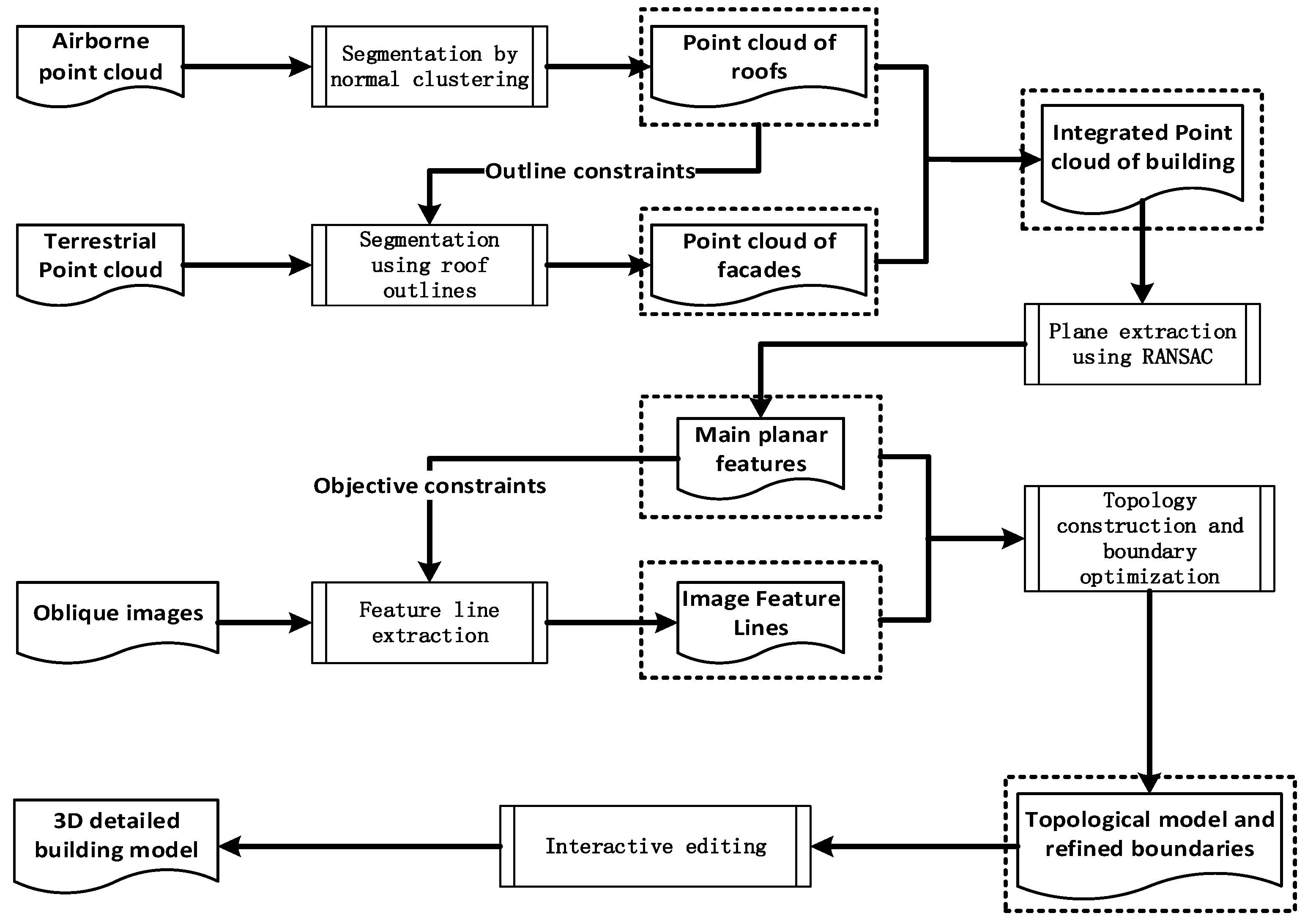
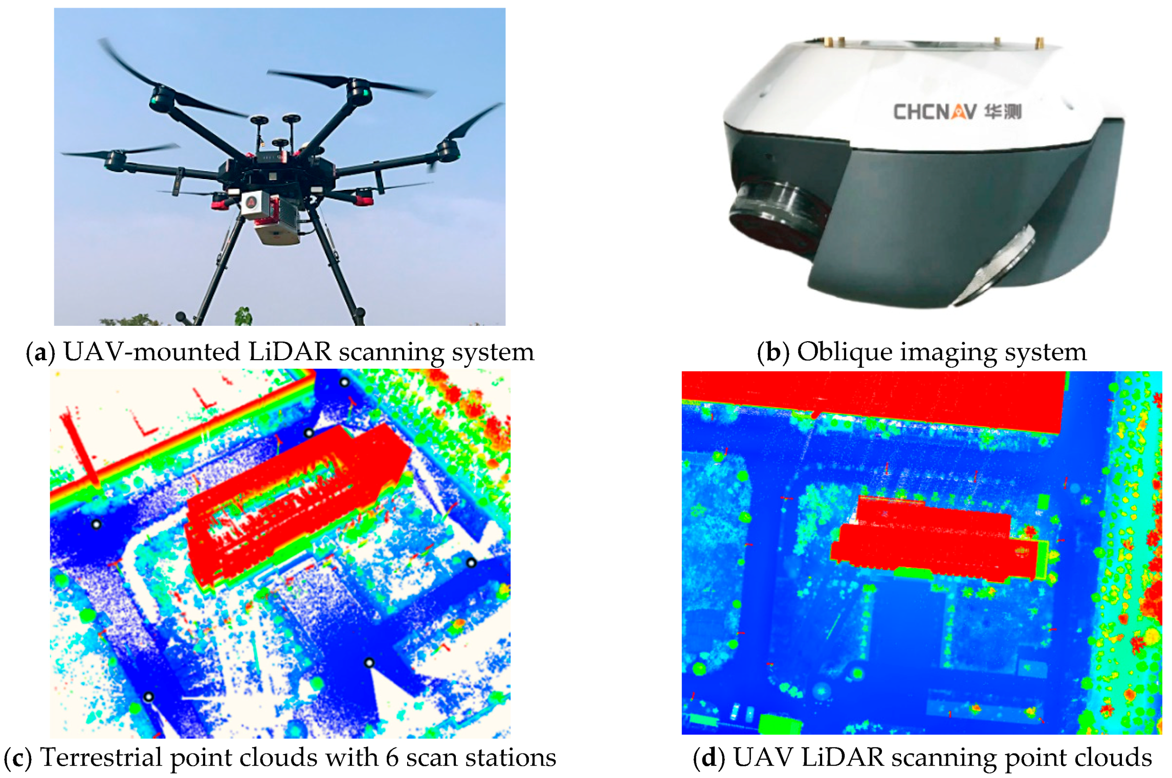
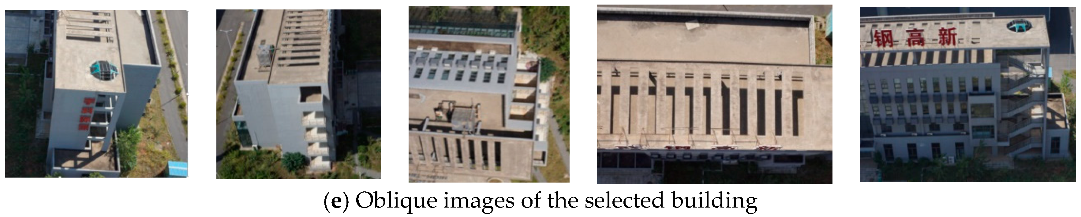
Figure 1 illustrates the main procedure of the proposed method. First, building roofs are extracted from UAV LiDAR scanning point clouds by normal vector clustering and segmentation. Using the building roofs as outline constraints, their corresponding facade areas in terrestrial ground point clouds are efficiently identified to obtain the integrated UAV and terrestrial points clouds belonging to the same building. Second, building plane primitives are extracted from the integrated point clouds by the Random Sample Consensus (RANSAC) algorithm [32], which are further used as planar objective constraints during the feature line extraction from oblique images. Third, feature lines are employed to improve the reconstruction accuracy of building outlines during the process of topology construction and boundary optimization. Finally, the approaches of interactive topology editing and texture mapping are used to achieve the desired refined building models. It should be noted that the prerequisite is the fine spatial registration of multi-source point clouds and remote sensing images.

2.1. Building Segmentation from UAV LiDAR Scanning Point Clouds

The building points, that is, point clouds denoting the same building, are achieved by the segmentation of UAV LiDAR scanning point clouds, which involves the following two steps.
(1) Ground points elimination by CSF. The Cloth Simulation Filtering (CSF) algorithm [33] is applied to filter out the ground point clouds. It uses a piece of cloth to generate a fitting surface via operations such as gravity displacement, intersection check, and internal force. The ground points are then filtered out by the height differences between the initial LiDAR points and the fitted ground surface. The parameters of CSF are easy to set, so it is accordingly adopted for filtering of our point clouds.
(2) Extraction of building roofs and facades. Building roofs and facades are mainly vertical or horizontal planes. Accordingly, using normal vector estimation of point clouds and the angles between normal vectors and their vertical directions, the horizontal points and vertical points from non-ground points can be identified using a simple normal angle thresholding scheme. The k-means clustering algorithm with Euclidean distance is adopted to group the labelled horizontal points and vertical points. Owing to the irregular distribution of normal vectors, the number of points and area of vegetation regions are limited to a relatively small range. Setting an appropriate threshold to the number of points in each cluster, the points of vegetation region can also be filtered out. The remaining points in other clusters are identified as building roofs and facades.

2.2. Plane Primitives and Feature Lines Extraction

Most building surface models could be divided into two parts: the multi-scale planes and their edges. For an accurate building reconstruction with high automation, two main steps are adopted to simultaneously improve the accuracy of surface position and edge integrity. The multi-source point clouds are used to ensure the surface accuracy, while oblique images are used for good edge performance. The details are explained as follows.
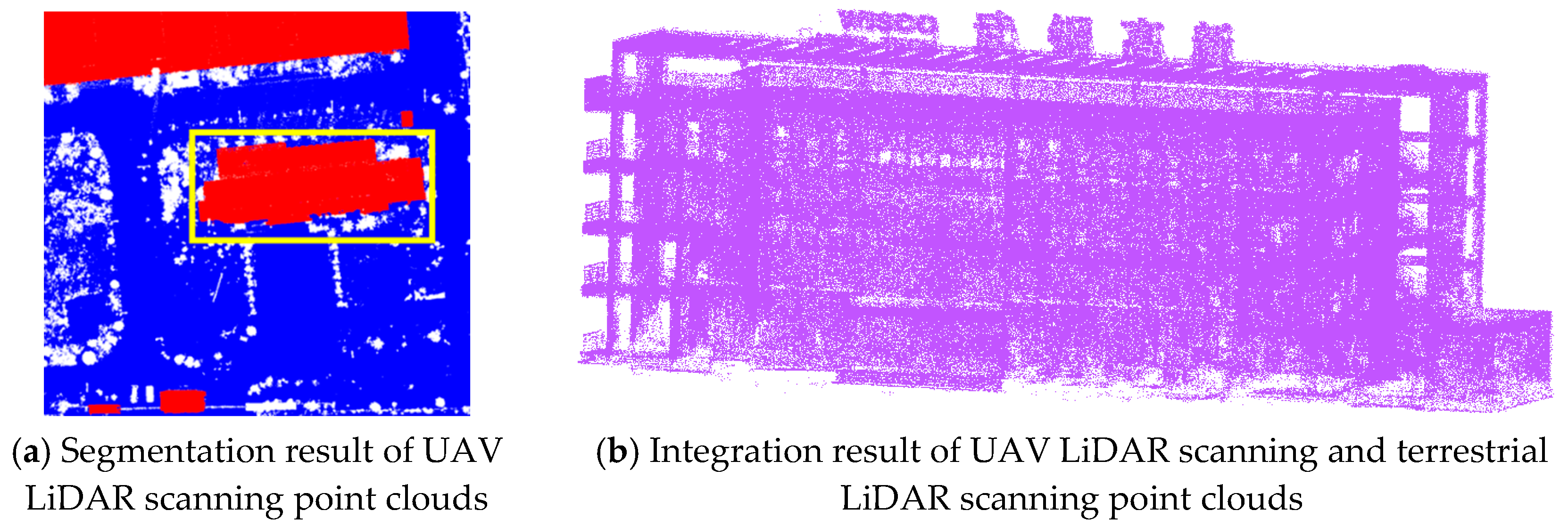
(1) The extraction of building plane primitives from multi-source point clouds. The plane primitives are main features of a building frame structure, and hence the robust planar surface extraction is a significant step for the building model reconstruction. The primitive extraction is implemented in three steps. First, an approximate building bounding box is calculated from the building roof and facade points extracted from UAV LiDAR scanning point clouds, where building points within the bounding box are selected from the terrestrial scanning point clouds. Later, the RANSAC algorithm is used to extract plane primitives from the integrated point clouds belonging to the same building. The points are clustered according to the normal vectors at first place. To promote iterative convergence, the mean value of normal directions and their centroid are used as the initial plane parameter. Finally, the Alpha Shape [34] method is used to extract the boundary of segmented planes because of its flexibility.
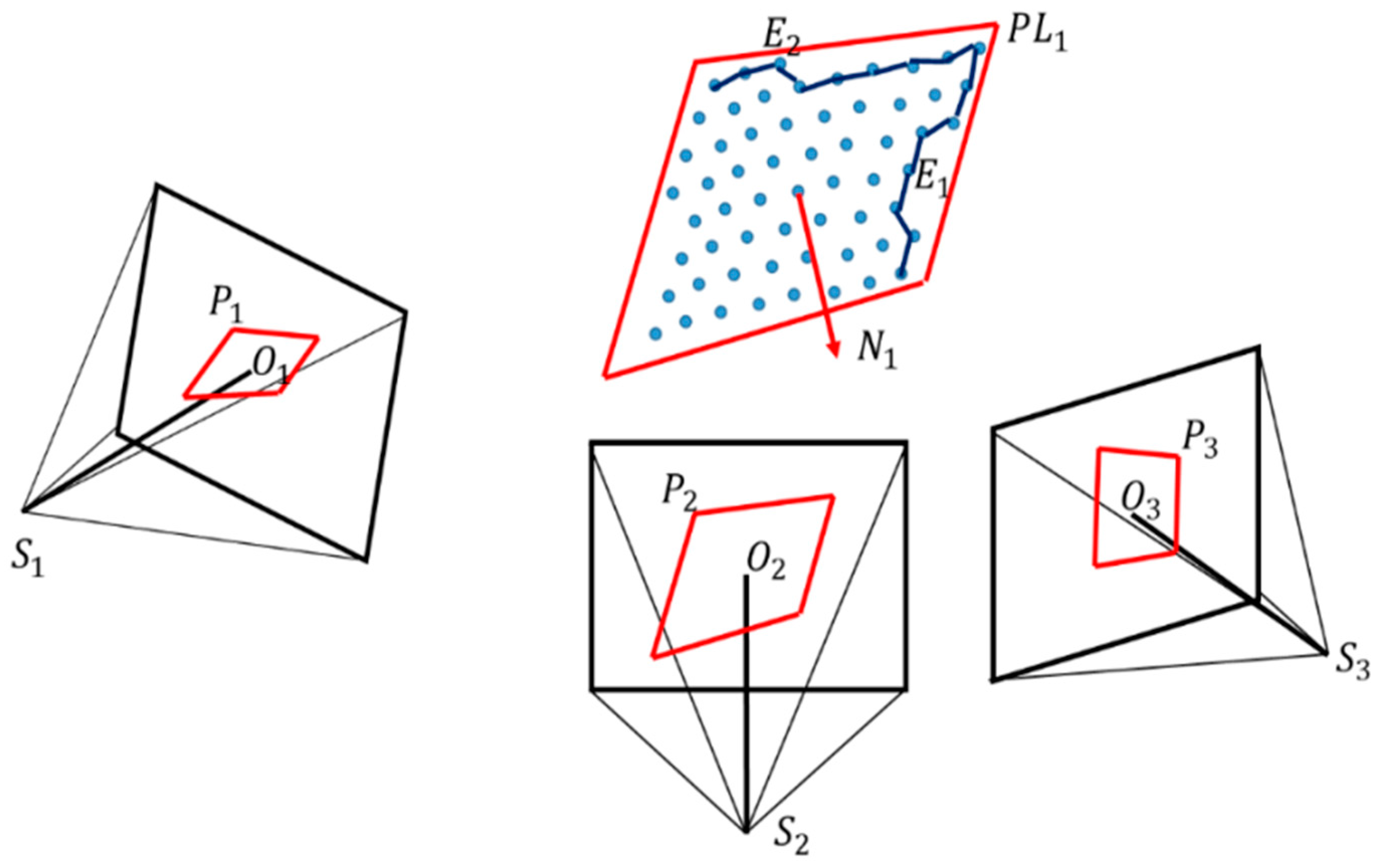
(2) Feature line extraction from oblique images. The surface accuracy of building plane primitives extracted from the point clouds is high. However, owing to factors such as discretization, noise, and occlusion, the plane boundaries are jagged or even partially missing (e.g., E 1 and E 2 in Figure 2), especially for windows and doors. In contrast, the resolution of oblique images is much higher and uniform, and hence it can provide much more detailed and accurate edge information with greyscale variations in the images. Accordingly, we combine the image edge information with the plane primitives to make a complete surface model.
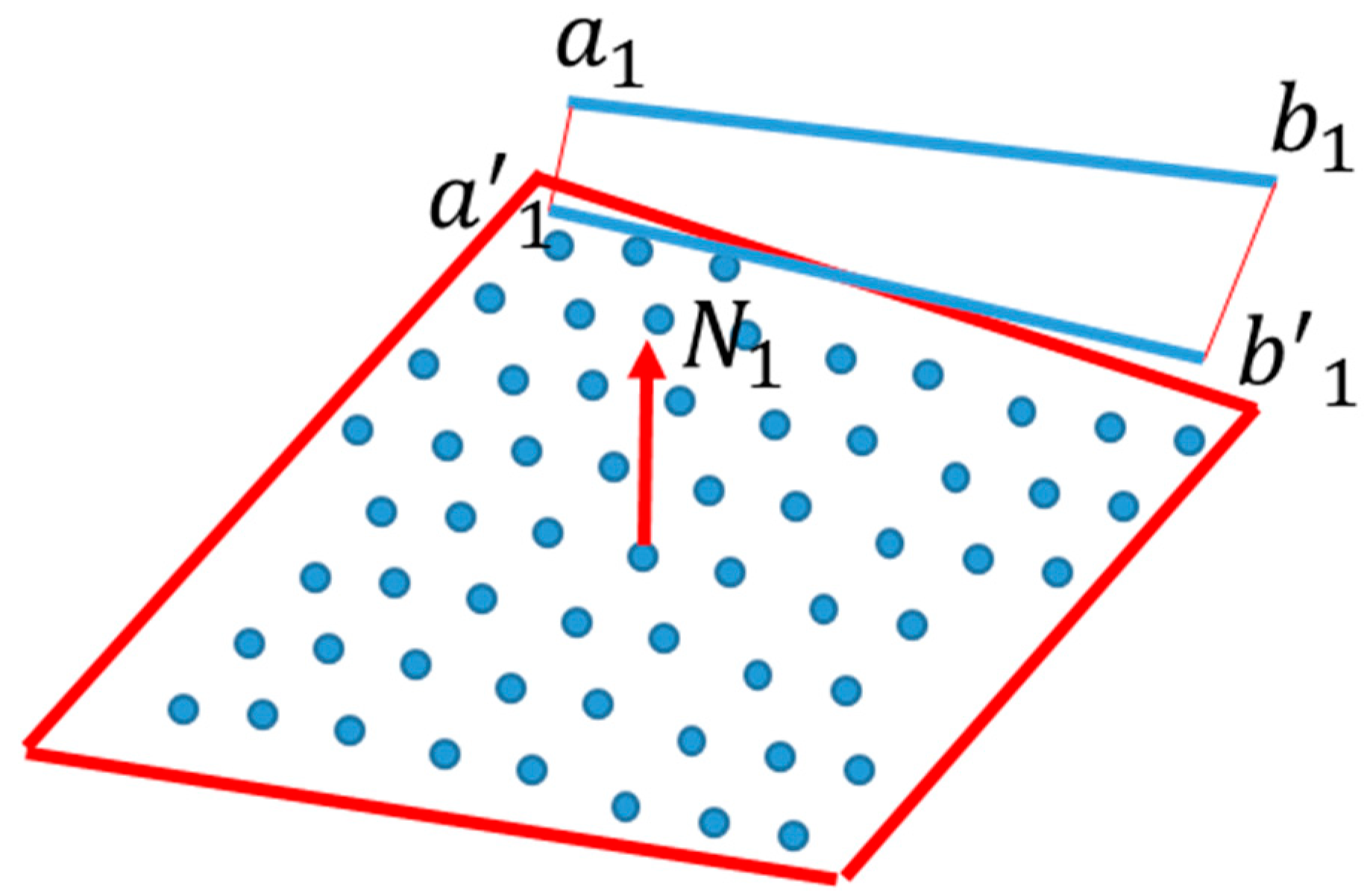
The procedure of image feature line extraction includes two steps: image selection and line matching. The image selection is to choose the most appropriate stereo image pair for the feature lines matching. Since the projection position of extracted planar surfaces is arbitrary, the closer the image is to its orthographic direction, the better its edge feature performance. To select the stereo image with the best imaging angle, each plane primitive is projected to the images. The top two images with the biggest projection polygon area are selected for the stereo lines matching. For example, the P 1 , P 2 and P 3 in Figure 2 represent the projections of the segmented plane P L 1 to the image S 1 , S 2   and   S 3 , where N 1 is the normal vector of P L 1 . Since the comparison relationship of area between P 1 , P 2 and P 3 is A r e a P 2 > A r e a P 3 > A r e a P 1 ( A r e a P indicates the area of projection plane), the image S 2   and   S 3 are selected for the feature line extraction.
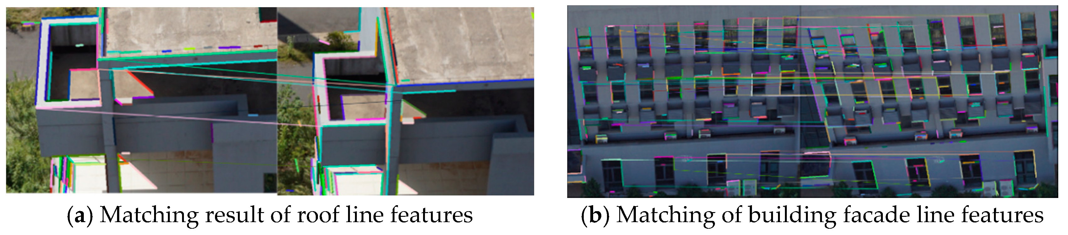
During the process of feature line extraction, the widely used Edge Drawing Line (EDLine) [35] method is used to extract feature lines, and the Line Band Descriptor (LBD) [
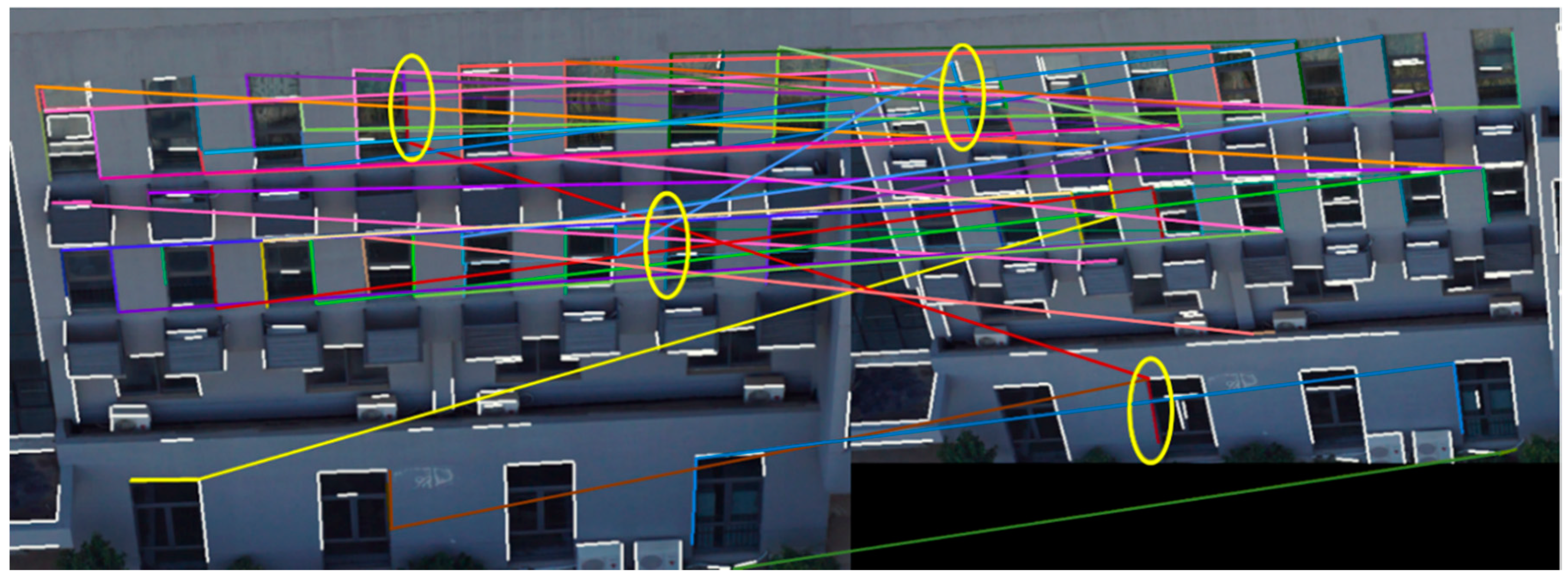
35] is imported for the description of lines. It should be noted that the initial matching method is used to construct an adjacency matrix, and matching lines are then acquired from the consistency iteration computation. For the matching of building area in oblique images, because of the repeating textures and similarity of local greyscale distribution, it is difficult to obtain the correct matching lines. For example, the white lines in Figure 3 represent the lines that failed to be matched, whereas the lines on the left and right image connected by a line with the same colour show the matching result. The yellow ellipses in boldface denote the incorrect matching pairs, and only a few lines are correctly matched.
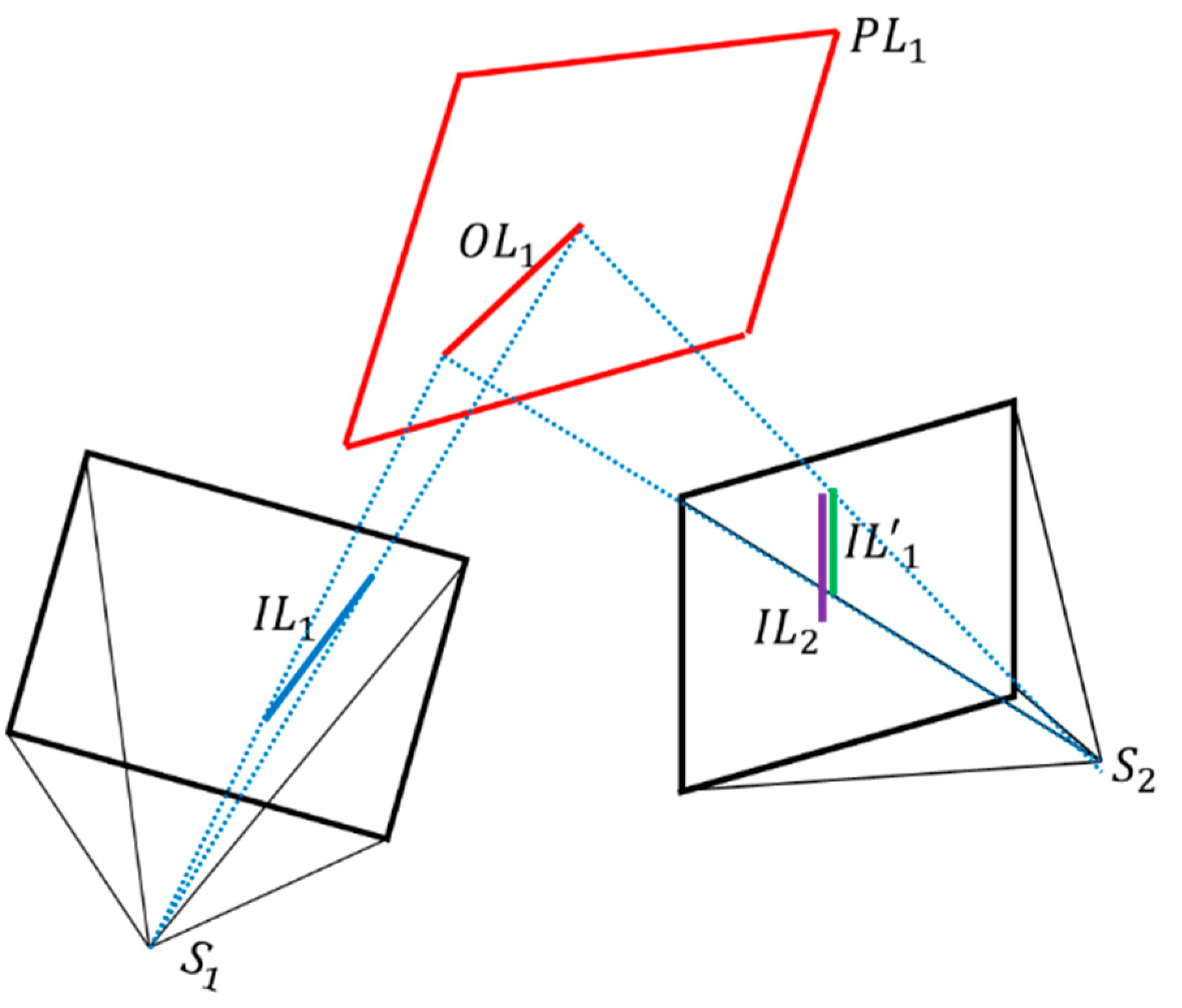
Therefore, the extracted planes from point clouds are again used as objective constraints to improve the matching results. During the line matching process, the modification and improvement of the original algorithm is that the corresponding objective plane is employed to calculate the approximately reliable initial matching positions of feature lines on the reference image. As illustrated in Figure 4, I L 1 and I L 2 represent the edge lines extracted from the projection area of objective plane P L 1 in the images S 1 and S 2 respectively. O L 1 denotes the forward intersection of I L 1 and P L 1 , and I L 1 is the back projection of O L 1 onto the image S 2 , representing the initial matching positions of I L 1 . If I L 2 is the matching line of I L 1 , I L 2 should be close to I L 1 , and their LBD vector should be consistent with each other, which could make the matching result more reliable.
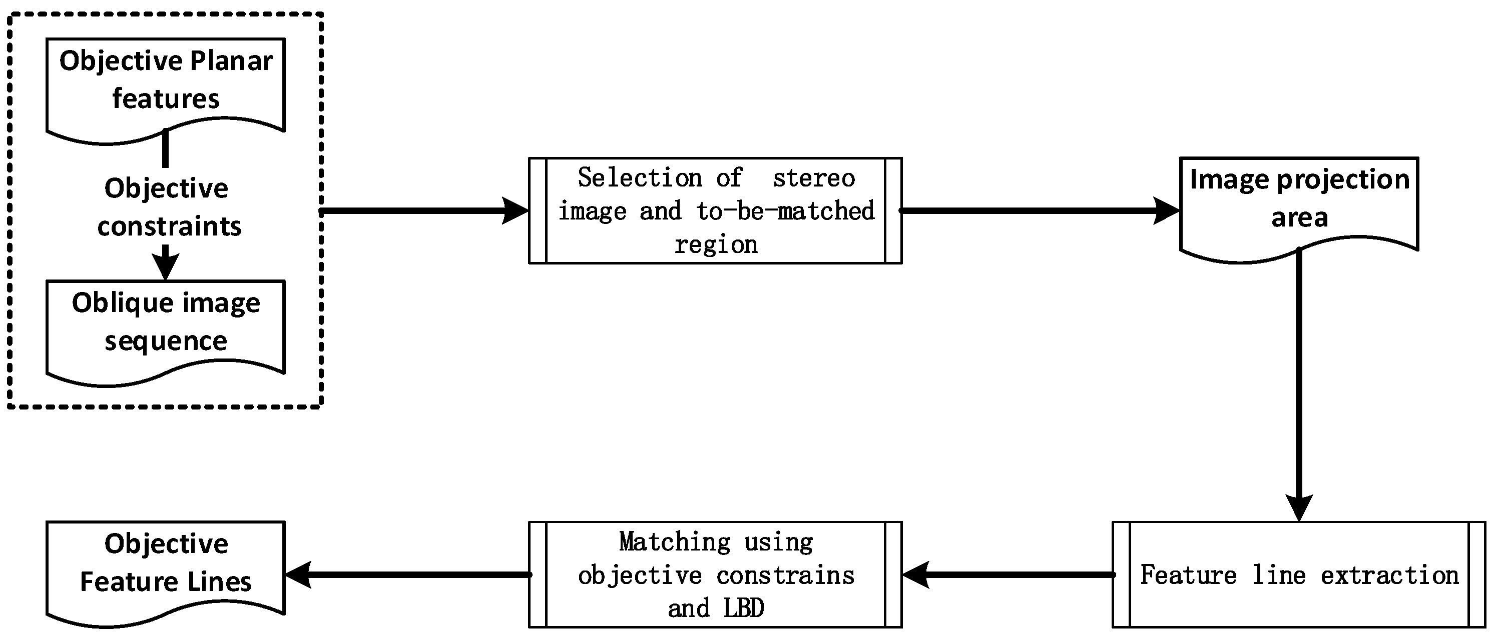
Moreover, Figure 5 shows the main steps of the improved feature line matching algorithm. The extracted planes are first employed to select the image stereo with the best angle. After that, the EDLine method is used to extract the matching feature lines from the projection area. To obtain a better matching result, the planar surfaces obtained from the first step are again used as constraints to provide the initial positions for potential matchings.

2.3. Topology Graph Construction and Boundary Optimization

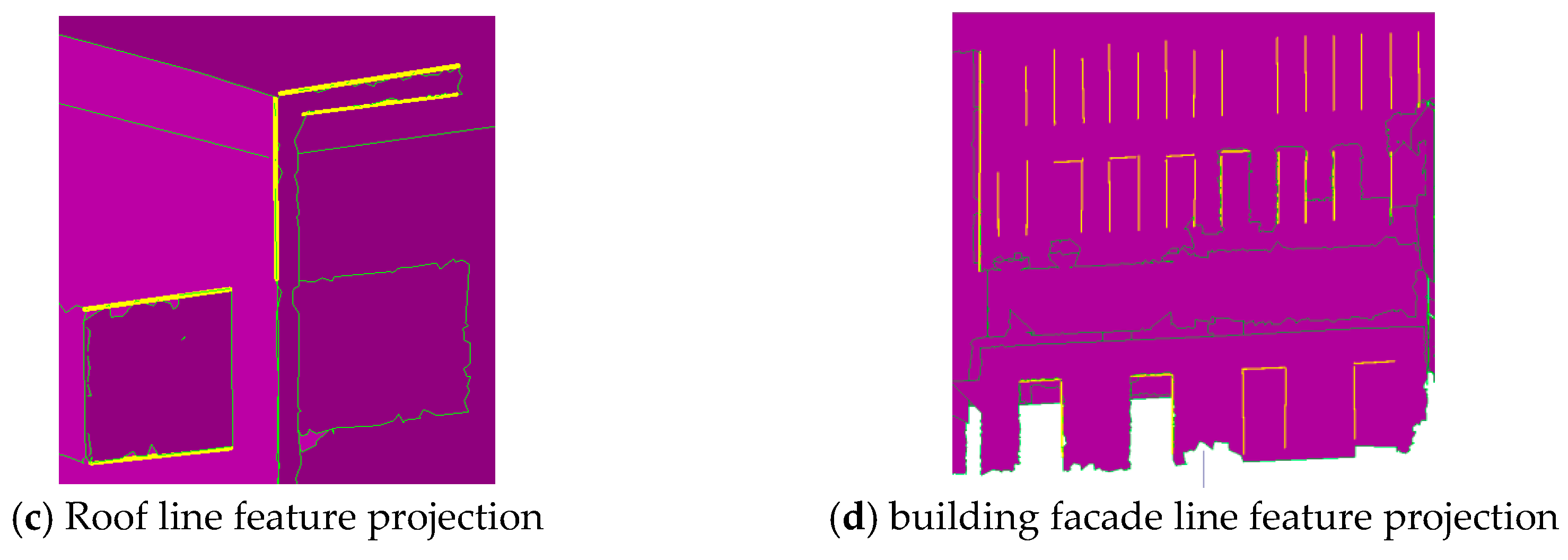
Through the abovementioned steps, the accurate planar surfaces and edges are acquired automatically. However, the boundaries of surfaces and extracted feature edges still need to be fused and optimized for a consistent boundary expression. To generate the initial building model frame with full automation, three steps including feature line projection, topology graph creation and boundary optimization are further employed in this section. They are explained in the following paragraphs.
(1) Image feature line projection. The feature line extracted from images mainly includes the outline of walls, windows, and balconies. Because of the accuracy inconsistency between the stereo matching lines and the extracted planar surface, it is necessary to project the image feature edge line to the objective planes to establish the boundary constraints. As shown in Figure 6, during the projection of feature line to corresponding segmented plane, a 1 b 1 represents stereo forward intersection of matching lines, and a 1 b 1 represents the result of projecting a 1 b 1 along the plane’s normal vector N 1 to the plane. The parameter D p r j of the minimum projected distance (shown as a 1 a 1 and b 1 b 1 in Figure 6) is used in order to eliminate the possible incorrect matching, as well as a threshold A n g p r j to determine whether the direction of the line is approximately perpendicular to the normal vector of the projected plane.
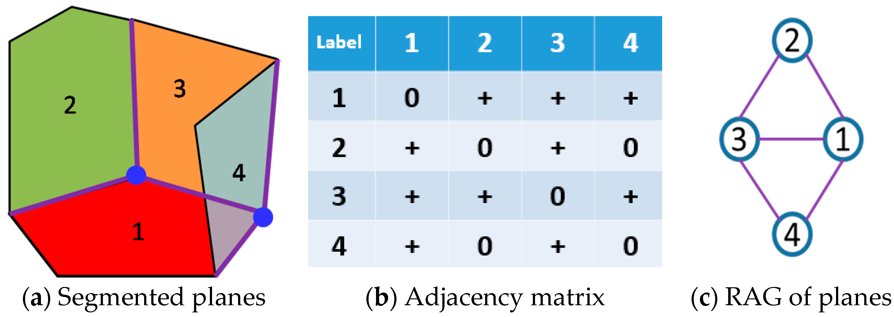
(2) Topology graph creation using RAG. Using the plane segmentation in Figure 7a, the topology graph RAG (Region Adjacent Graph) is constructed according to the adjacency relationship of plane primitives. Two steps are involved in the construction of RAG. The first step is to compute the adjacency matrix in Figure 7b, which is a symmetric matrix with diagonal elements as zero. All the non-zero elements in the matrix are then extracted and transformed into an undirected graph, as shown in Figure 7c. The boundaries indicate that two planes are adjacent and have intersections. The procedure of building the adjacency relationship is as follows. The angles between the normal vector of the planes is calculated. If the angle is smaller than the threshold (normally set to be 15 degrees), it means that the two planes are nearly parallel and not adjacent. After that the boundary of segmented plane primitives is traversed with short connected lines. The short boundary lines in the plane a are traversed to calculate the project distances d 1 and d 2 from the pairwise line endpoints to the plane b , as well as the line length d L . If d 1 and d 2 are both smaller than the distance threshold d , and the projected point along the normal vector of plane b is within the range of plane b , the short line is adjacent to plane b and is added into the set of adjacent boundary lines. Finally, all the short edge lines in the plane a are computed and the sum length L of lines in S is calculated. If L T L ( T L is the threshold of length), the planes a and b are adjacent.
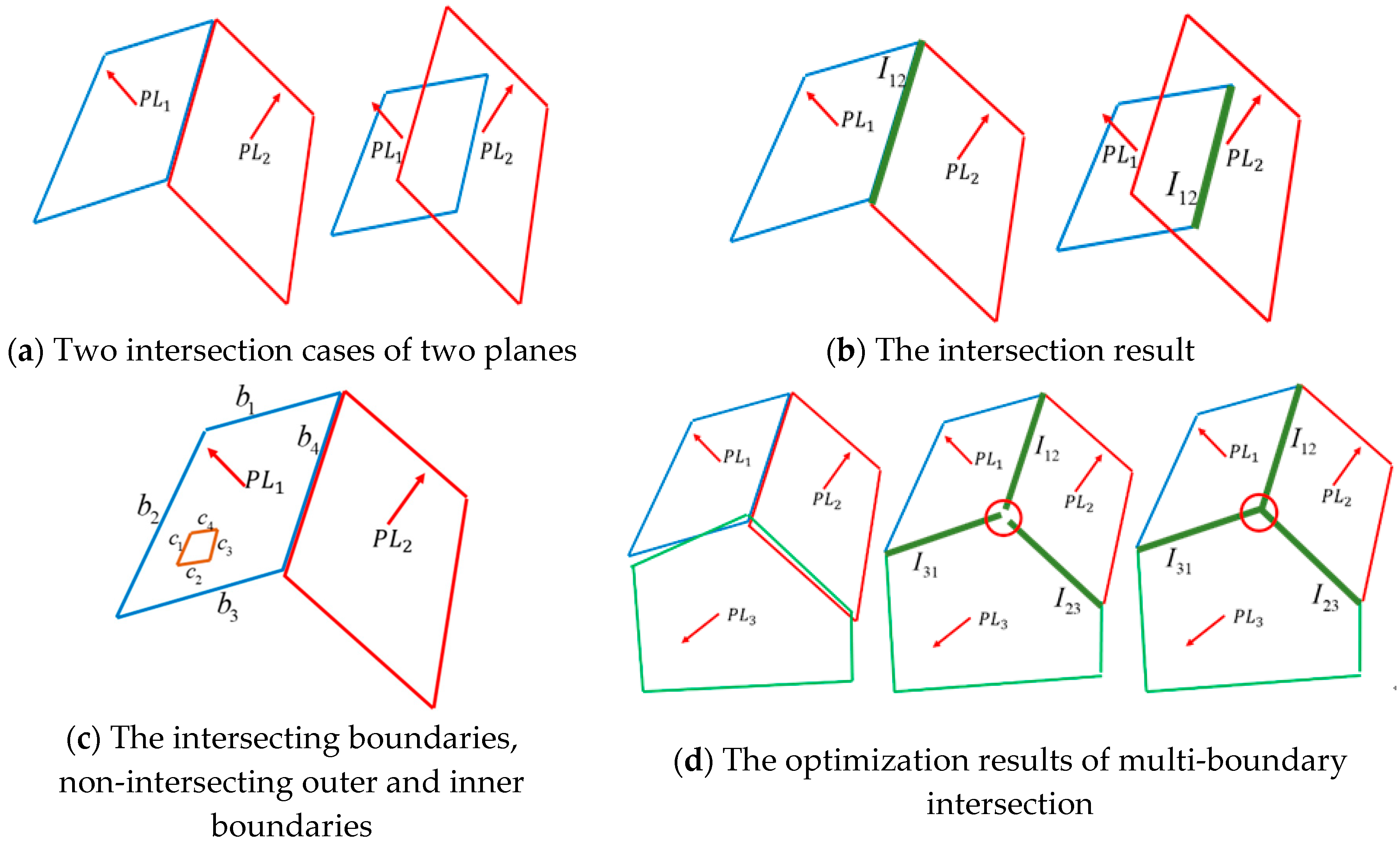
(3) Intersection and boundary optimization. The intersection of the two planes is calculated using the constructed RAG graph. Two cases when two planes intersect with each other are considered in the intersection processing, as shown in Figure 8a. In Figure 8a, P L 1 and P L 2 represent two adjacent planes. The endpoint of the intersection in each plane is determined by the distance from the original boundary point to the intersection line (Figure 8b). The boundaries of each plane are divided into three categories: intersecting boundaries, non-intersecting outer boundaries and non-intersecting inner boundaries. For example, in Figure 8c, b 1 , b 2 and b 3 represent non-intersecting outer boundaries, b 4 represents the intersection boundary, and c 1 , c 2 , c 3 and c 4 represent the non-intersecting inner boundaries. The optimization of intersecting boundaries is conducted when more than two planes intersect with each other. The endpoint of an intersected boundary is used to search for adjacent endpoints of intersecting boundaries in other planes. If the adjacent boundaries belong to planes within the minimum closed loop of the RAG graph, the boundaries are supposed to intersect at the same point. The intersection point is further calculated using the least squares method (shown in Figure 8d).
Non-intersecting outer boundaries optimization is used to integrate the original boundaries from point clouds with the projected image feature lines. If the original boundary lines are close enough to the image feature lines, they are replaced by the projected feature line as the new boundary line section. This process is also applied to the non-intersecting inner boundaries such as a window. The boundaries are further regularized to ensure that the result is consistent with the actual shape of buildings, where the main direction adjustment method proposed by Dai et al. [36] is used. It should be noted that the optimized intersecting boundaries should be kept unchanged, and only the non-intersecting outer and inner boundaries are processed.

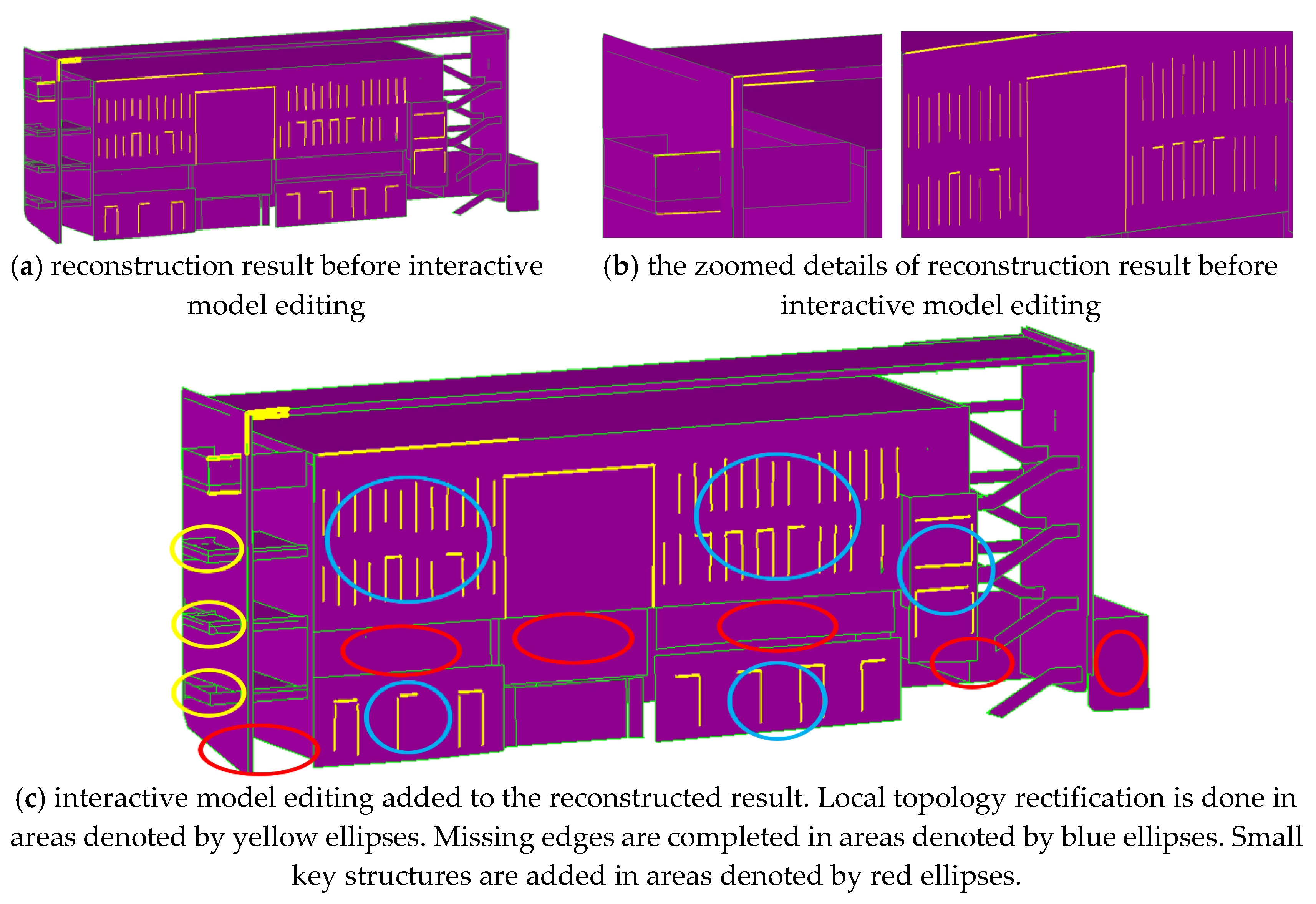
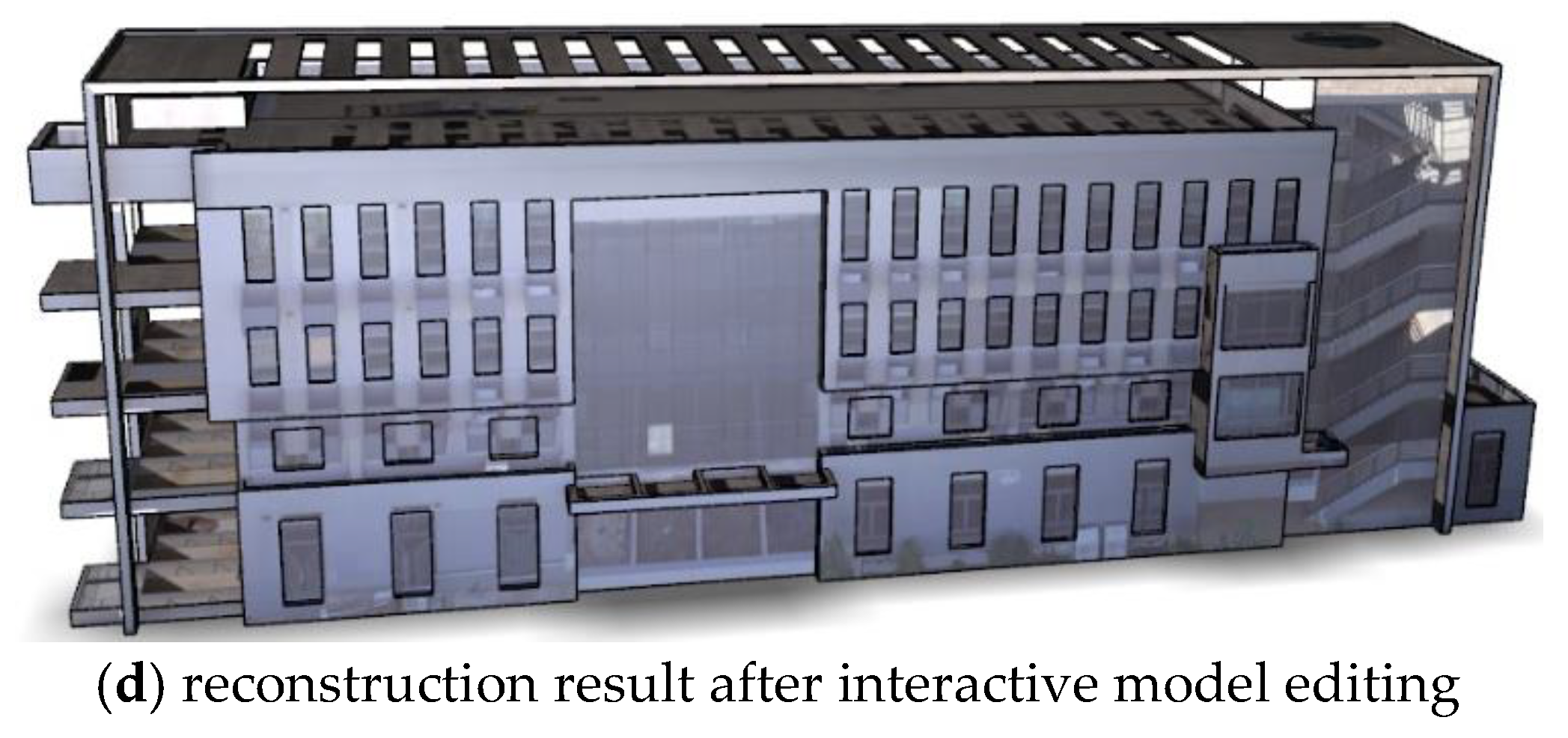
2.4. Interactive Model Editing

The main building body including the roofs, main facades, and window boundaries could be extracted and reconstructed with the preceding pipeline. However, there are still some small problems such as topological errors or integrity deficiency because of local data missing or topology complexity. Accordingly, the interactive manual editing., e.g., further topological inspection and geometrical detail adjustment, is still indispensable for reconstructing a refined building model. In this study, we use the software 3D Max for further interactive model editing and obtain the final detailed building model.

3. Results and Analysis

3.1. Datasets

To verify the performance of proposed algorithm, the UAV LiDAR scanning point clouds, terrestrial LiDAR scanning point clouds and oblique images of a certain urban area in Wuhan City, China were collected. The UAV LiDAR scanning point clouds data was obtained using a UAV-mounted mobile laser scanning system that integrates a RIEGL VUX laser scanner and a Position and Orientation System (POS) with an Inertial Measurement Unit (IMU) of 200 HZ data acquisition rate and drift smaller than 0.01 ° h 1 . According to the technical specifications, the angle measurement resolution of the laser scanner is 0.001 ° , and the orientation and attitude accuracy of the POS are 0.005 ° . The flight height is about 80 m and the angular step width is selected to be 0.006 ° , which makes the spatial resolution of point clouds to be 10 cm. The oblique images were captured by an oblique imaging system with five SONY ILCE-5100 cameras, with one mounted in the vertical direction (focal length 35 mm) and four in 45 ° tilted direction (focal length 25 mm). The pixel size of each camera is 3.9 μ m , and the image resolution is 6000 × 4000. The flight height is about 150 m in data acquisition, providing the oblique images with ground spatial distance (GSD) of 2 cm. Both systems were provided by CHC Navigation Technology Co. Ltd. (Shanghai, China). The terrestrial point clouds were collected using an RIEGL VZ-400 laser scanner with a field of view of 360 ° in the horizontal direction and 100 ° in the vertical direction. The resolution of the terrestrial data is approximately 2 cm. Figure 9 shows an overview of the hardware system and the experimental multi-source data. A building with 4 floors is contained in the point clouds, which is mainly constituted of planar surfaces such as walls, windows and roofs. The UAV LiDAR scanning point clouds include approximately 8 million points. A total of 6 scan stations are included in the terrestrial point clouds, and the number of points in each scan station is approximately 10 million. A total of 533 × 5 oblique multi-view images were used.
Moreover, in order to register the multi-source data and verify the reconstruction accuracy, 21 ground control points (GCPs) were acquired using real time kinematic (RTK) GPS and total station. These GCPs are located at the building outline corners, window corners and ground artificial structure corners (e.g., flower-bed and floor tile). The corners of the building outline and ground artificial structures were acquired using RTK under reliable observation conditions, and the window corner measurements were acquired using total station. Since the accuracy of RTK is trustworthy to be around 2 cm, the GCPS are reliable to be used as reference and verification data.
The terrestrial point clouds data from different scan stations were first registered using signalized target points, and then aligned with the UAV LiDAR scanning point clouds using Riscan Pro software from Riegl (http://www.riegl.com/products/software-packages/riscan-pro/) through 8 GCPs selected from the 21 GCPs. The registration is optimized by ICP (Iterative Closest Points) algorithm implemented in PCL (Point Cloud Library, http://pointclouds.org/) to obtain the optimized alignment result. The accuracy of the registered point clouds is verified through extracting the corresponding corners by fitting local planes or lines to get the intersection points and comparing them to the remaining 13 GCPs. The root mean square error (RMSE) of 13 intersection points is 3.7 cm, which indicates a good registration result. The aerial triangulation of oblique images is conducted using 11 GCPs from the same control point set using Context Capture software (version 4.4.8 win64) (https://www.bentley.com/zh/products/brands/contextcapture). The RMSE of reprojection error is 0.56 pixels. Moreover, 10 corresponding points were acquired manually from the oblique stereo images through forward intersection, and then they are compared to the remaining 10 check points. The obtained RMSE is 4.4 cm, which indicates that the oblique images are positioned and oriented with high accuracy.

3.2. Experimental Results

3.2.1. Parameters Setting

The CSF algorithm was used to filter out the ground points. Parameters C S F G r i d and C S F D i s t are the grid resolution and the distance between ground and non-ground points, respectively. They are set as recommended in the paper by Zhang et al. [33]. The C S F G r i d was set to 0.5 m in this study, which is five times of average point span. Given the flatness of the test area, C S F D i s t was set to a fixed value of 0.5 m. To maintain a balance between efficiency and accuracy, during the clustering process of roof and facade point clouds, the distance parameter C l u D i s t and parameter C l u N u m of cluster points number were set to 1 m and 200 respectively, according to the point density and the minimum area of the main roof planar surface. The parameters used in the RANSAC for planar surface extraction were set as recommended by Schnabel R. et al. [37].
The line matching parameters were specified as recommended by Zhang et al. [35]. The distance parameter P D i s t used to judge whether a point is near a plane or not during the feature line projection and topology graph reconstruction presented in Section 2.3 was set to 0.2 m, which is two times of average point span. The parameter T L was set to 1m to determine whether a plane is adjacent to another or not. Moreover, through trial and error, the minimum projected distance D p r j and angle threshold A n g p r j were set to 0.5 m and 75 degrees to eliminate possibly incorrect matchings.

3.2.2. Building Segmentation and Planar Surface Extraction

Figure 10a illustrates the segmentation result of UAV LiDAR scanning point clouds, in which the red areas indicate the artificial building regions. During the experiment, the segmented main building area is taken as the selected object to be reconstructed, as shown in the yellow rectangular region in Figure 10a. The corresponding terrestrial point clouds of the same building were extracted along the vertical direction of the object in Figure 10a. Figure 10b shows the integration result of point clouds from different platforms.
The plane segmentation and surface reconstruction results are shown in Figure 11a,b. Figure 11c is the enlarged view of the red rectangle area in the left side of Figure 11b. From Figure 11c, it can be found that the plane edges are sharply jagged owing to the un-uniform distribution, noise and occlusion of point clouds.

3.2.3. Image Feature Lines Extraction and Building Reconstruction

The line matching results of the roof and a facade using the corresponding planar surface as objective constraints are shown in Figure 12a,b. It can be seen from Figure 12a,b that almost all lines are matched successfully. The results of projecting the forward intersected lines to the corresponding segmented planes are shown in Figure 12c,d.
The building reconstruction results before and after interactive model editing are shown in Figure 13. Figure 13a shows the reconstruction result before interactive model editing and Figure 13b shows the zoomed details. Comparing Figure 13a with Figure 11b, after intersecting boundaries optimization, non-intersecting outer and inner boundaries optimization using forward intersected lines and regularization, it can be seen that jagged boundaries are significantly improved and the small building elements such as windows missed in Figure 11b are supplemented by lines extracted from oblique images.
However, there are still some minor problems such as topological errors or integrity deficiency because of local data missing or topology complexity in the reconstruction result of Figure 13a. Actions should be taken to correct the topological errors and fill the missing parts to refine the model. Three manual interactive editing steps are implemented to refine the model: (1) The first step is to rectify the local topology reconstruction errors (as shown in yellow ellipse areas of Figure 13c) by extending plane primitives to the right adjacent plane to obtain the correct intersection line or point; (2) The second step is to complete missing edges of windows (as shown in blue ellipse areas of Figure 13d), assuming that the edges are either parallel or perpendicular; and (3) The third step is to add some small key structures, such as the the canopy and shadowed window (as shown in red ellipse areas of Figure 13c), based on manually extracted planar primitives and edge lines from the point clouds. The final reconstruction building model of our method is shown in Figure 13d.

3.3. Performance Evaluation

The algorithms of point clouds segmentation and image feature line extraction are implemented in C++ on a Win7 64-bit system platform. The main hardware configuration is Intel Core I7 and 16 G RAM, and the graphics card is Nvidia GeForce GTX 1080 Ti. Two state-of-the-art methods were used to compare with the modelling efficiency and accuracy of the proposed method, i.e., the complete manual reconstruction using the fusion point clouds based on 3DMAX (version is 2011 win64 bit) (https://www.autodesk.com/products/3ds-max/overview), and the multi-view oblique image for building model reconstruction using Context Capture (version 4.4.8 win64) (https://www.bentley.com/zh/products/brands/contextcapture). Moreover, 8 GCPs located at the windows and outline corners of the selected building were used to estimate the horizontal and elevation precision using the RMSE as the accuracy. The comparison of all reconstruction results from different methods is shown in Figure 14. In addition, Table 1 lists the results of time consumption and accuracy of the three methods.

4. Discussions

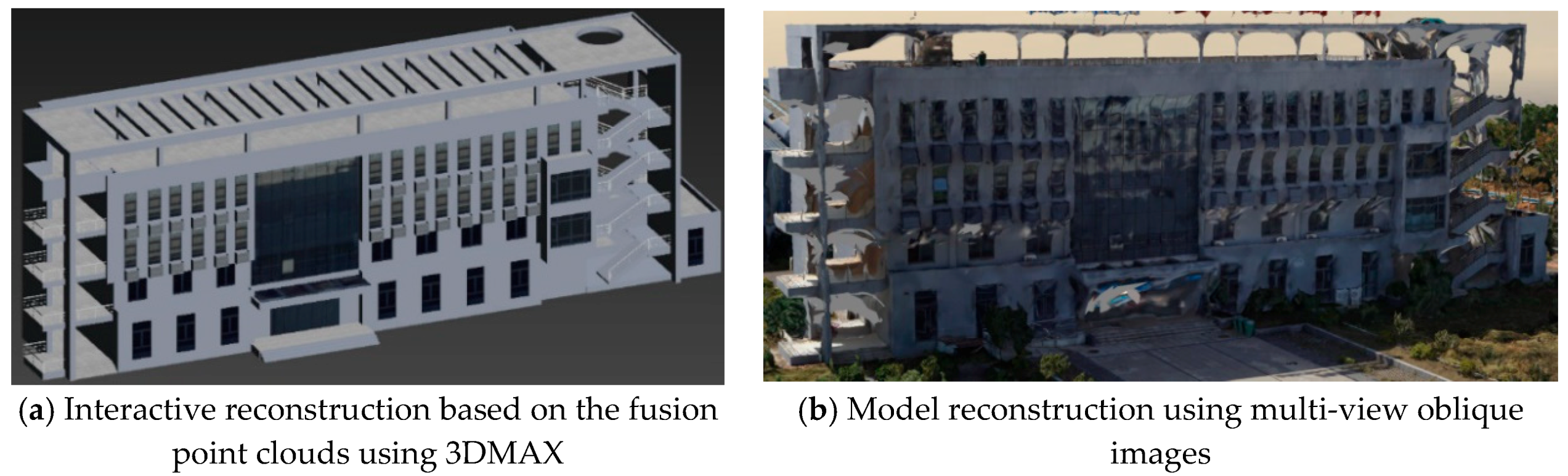
3D building reconstruction using multi-view oblique images can achieve fine scene restoration, but some obvious geometric deformation exists in certain local details, especially in the texture-less areas. The LiDAR sensors sample the building points discretely and the data of building edges cannot always be obtained, the precision of a building model reconstructed from point clouds manually is also limited. Compared with the reconstruction results from multi-view oblique images and only point clouds, the horizontal and elevation precisions of the building models from the proposed method are significantly improved. These improvements mainly benefit from the boundary-feature constraint of non-intersecting outer and inner boundaries, especially for the walls and windows.
In regard to efficiency, the reconstruction method using multi-view oblique images is time-consuming because of its dense matching and mesh reconstruction process. The manual 3D Max reconstruction method needs to collect boundary feature lines from complex point clouds interactively, which is labour-intensive, especially when occlusions and ambiguities occur with big probability. The presented method integrating multi-source data takes full advantage of the feature lines extracted from the combination of point clouds and images, and reconstruct the building main frame automatically and accurately, providing a more reliable reference for the later interactive editing. Thanks to the automatically reconstructed building main frame, the reconstruction efficiency of the proposed method is considerably promoted.
The proposed method provides an alternative way for the automatic and rapid reconstruction work of the building’s main outline, but the results still need interactive editing. Accordingly, more efforts are required to develop advanced methods to achieve a fully automatic reconstruction method of LoD3 building models in the future. Besides, we, in the future work, will propose multi-scale segmentation schemes of smooth surface primitives and enrich the existing primitive topology processing rules in the method to further improve the generalization and automation for complicated building structures.

5. Conclusions

This paper presents a method that implements multi-source remote sensing data to accurately and efficiently reconstruct the LoD3 building model in urban scenes. First, building roof planes extracted from UAV LiDAR point clouds are used to help determine the building facades in the terrestrial LiDAR point clouds. The integrated UAV and terrestrial points of the same building are then obtained to extract the building plane primitives. After that, the building models are reconstructed by intersecting the adjacent plane primitives and optimized by line features from oblique images. Minor manual interactive model editing work is conducted to refine the reconstructed building model, and the accurate LoD3 building model is finally obtained. The UAV LiDAR point clouds, terrestrial LiDAR point clouds and oblique images of a certain urban area in Wuhan City were collected and used to validate the proposed method. Experimental results on realistically collected multi-source data explain that our method can greatly improve the efficiency of LoD3 building model reconstruction and achieved better horizontal and elevation accuracies than other state-of-the-art methods.

Author Contributions

Xuedong Wen conceived and designed the experiments. Hong Xie developed the method framework. Hua Liu performed the resultant analysis. Li Yan provided comments and suggestions to improve the manuscript.

Funding

This research was funded by National Key R & D Program of China, grant number 2017YFC0803802.

Acknowledgments

The authors thank all the scientists who released their code under Open Source licenses and made our method possible.

Conflicts of Interest

The authors declare no conflict of interest.

References

  1. Kolbe, T.H. Representing and exchanging 3D city models with CityGML. In 3D Geo-Information Sciences; Springer: Berlin/Heidelberg, Germany, 2009; pp. 15–31. [Google Scholar]
  2. Suveg, I.; Vosselman, G. Reconstruction of 3D building models from aerial images and maps. ISPRS J. Photogramm. 2004, 58, 202–224. [Google Scholar] [CrossRef] [Green Version]
  3. Brenner, C. Building reconstruction from images and laser scanning. Int. J. Appl. Earth Obs. 2005, 6, 187–198. [Google Scholar] [CrossRef]
  4. Vanegas, C.A.; Aliaga, D.G.; Benes, B. Automatic extraction of Manhattan-world building masses from 3D laser range scans. IEEE Vis. Comput. Gr. 2012, 18, 1627–1637. [Google Scholar] [CrossRef] [PubMed]
  5. Xiong, B.; Elberink, S.O.; Vosselman, G. A graph edit dictionary for correcting errors in roof topology graphs reconstructed from point clouds. ISPRS J. Photogramm. 2014, 93, 227–242. [Google Scholar] [CrossRef]
  6. Perera, G.S.N.; Maas, H. Cycle graph analysis for 3D roof structure modelling: Concepts and performance. ISPRS J. Photogramm. 2014, 93, 213–226. [Google Scholar] [CrossRef]
  7. Wang, R.; Hu, Y.; Wu, H.; Wang, J. Automatic extraction of building boundaries using aerial LiDAR data. J Appl. Remote Sens. 2016, 10, 16022. [Google Scholar] [CrossRef]
  8. Zolanvari, S.I.; Laefer, D.F.; Natanzi, A.S. Three-dimensional building facade segmentation and opening area detection from point clouds. ISPRS J. Photogramm. 2018, 143, 134–149. [Google Scholar] [CrossRef]
  9. Wang, Q.; Yan, L.; Zhang, L.; Ai, H.; Lin, X. A Semantic Modelling Framework-Based Method for Building Reconstruction from Point Clouds. Remote Sens. 2016, 8, 737. [Google Scholar] [CrossRef]
  10. Pu, S.; Vosselman, G. Knowledge based reconstruction of building models from terrestrial laser scanning data. ISPRS J. Photogramm. 2009, 64, 575–584. [Google Scholar] [CrossRef]
  11. Wang, C.; Cho, Y.K.; Kim, C. Automatic BIM component extraction from point clouds of existing buildings for sustainability applications. Automat. Constr. 2015, 56, 1–13. [Google Scholar] [CrossRef]
  12. Lin, H.; Gao, J.; Zhou, Y.; Lu, G.; Ye, M.; Zhang, C.; Liu, L.; Yang, R. Semantic decomposition and reconstruction of residential scenes from LiDAR data. ACM Trans. Gr. 2013, 32, 66. [Google Scholar] [CrossRef]
  13. Nan, L.; Sharf, A.; Zhang, H.; Cohen-Or, D.; Chen, B. Smartboxes for interactive urban reconstruction. In Proceedings of the SIGGRAPH ′10, Los Angeles, CA, USA, 26–30 July 2010; p. 93. [Google Scholar]
  14. Fryskowska, A.; Stachelek, J. A no-reference method of geometric content quality analysis of 3D models generated from laser scanning point clouds for hBIM. J. Cult. Herit. 2018, 34, 95–108. [Google Scholar] [CrossRef]
  15. Wang, J.; Zhu, Q.; Wang, W. A Dense Matching Algorithm of Multi-view Image Based on the Integrated Multiple Matching Primitives. Acta Geod. Cartogr. Sin. 2013, 42, 691–698. [Google Scholar]
  16. Rupnik, E.; Nex, F.; Remondino, F. Oblique multi-camera systems-orientation and dense matching issues. Int. Arch. Photogramm. Remote Sens. Spat. Inf. Sci. 2014, 40, 107. [Google Scholar] [CrossRef]
  17. Haala, N.; Rothermel, M.; Cavegn, S. Extracting 3D urban models from oblique aerial images. In Proceedings of the 2015 Joint Urban Remote Sensing Event (JURSE), Lausanne, Switzerland, 30 March–1 April 2015; pp. 1–4. [Google Scholar]
  18. Rupnik, E.; Nex, F.; Toschi, I.; Remondino, F. Aerial multi-camera systems: Accuracy and block triangulation issues. ISPRS J. Photogramm. 2015, 101, 233–246. [Google Scholar] [CrossRef]
  19. Xiao, J.; Fang, T.; Zhao, P.; Lhuillier, M.; Quan, L. Image-based street-side city modeling. In Proceedings of the SIGGRAPH Asia ′09, Yokohama, Japan, 16–19 December 2009; p. 114. [Google Scholar]
  20. Micusik, B.; Kosecka, J. Piecewise planar city 3D modeling from street view panoramic sequences. In Proceedings of the 2009 IEEE Conference on Computer Vision and Pattern Recognition, Miami, FL, USA, 20–25 June 2009; pp. 2906–2912. [Google Scholar]
  21. Tian, Y.; Gerke, M.; Vosselman, G.; Zhu, Q. Knowledge-based building reconstruction from terrestrial video sequences. ISPRS J. Photogramm. 2010, 65, 395–408. [Google Scholar] [CrossRef]
  22. Dahlke, D.; Linkiewicz, M.; Meissner, H. True 3D building reconstruction: Facade, roof and overhang modelling from oblique and vertical aerial imagery. Int. J. Image Data Fus. 2015, 6, 314–329. [Google Scholar] [CrossRef]
  23. Toschi, I.; Ramos, M.M.; Nocerino, E.; Menna, F.; Remondino, F.; Moe, K.; Poli, D.; Legat, K.; Fassi, F. Oblique photogrammetry supporting 3D urban reconstruction of complex scenarios. Int. Arch. Photogramm. Remote Sens. Spat. Inf. Sci. 2017, 42, 519–526. [Google Scholar] [CrossRef]
  24. Wu, B.; Xie, L.; Hu, H.; Zhu, Q.; Yau, E. Integration of aerial oblique imagery and terrestrial imagery for optimized 3D modeling in urban areas. ISPRS J. Photogramm. 2018, 139, 119–132. [Google Scholar] [CrossRef]
  25. Pu, S. Knowledge Based Building Facade Reconstruction from Laser Point Clouds and Images (2010). Available online: https://library.wur.nl/WebQuery/titel/1932258 (accessed on 28 February 2019).
  26. Huang, X.; Zhang, L. A multilevel decision fusion approach for urban mapping using very high-resolution multi/hyperspectral imagery. Int. J. Remote Sens. 2012, 33, 3354–3372. [Google Scholar] [CrossRef]
  27. Gruen, A.; Huang, X.; Qin, R.; Du, T.; Fang, W.; Boavida, J.; Oliveira, A. Joint processing of UAV imagery and terrestrial mobile mapping system data for very high resolution city modeling. Int. Arch. Photogramm. Remote Sens. Spat. Inf. Sci. 2013, 175–182. [Google Scholar] [CrossRef]
  28. Yang, L.; Sheng, Y.; Wang, B. 3D reconstruction of building facade with fused data of terrestrial LiDAR data and optical image. Opt.-Int. J. Light Electron. Opt. 2016, 127, 2165–2168. [Google Scholar] [CrossRef]
  29. Kedzierski, M.; Walczykowski, P.; Wojtkowska, M.; Fryskowska, A. Integration of point clouds and images acquired from a low-cost nir camera sensor for cultural heritage purposes. Int. Arch. Photogramm. Remote Sens. Spat. Inf. Sci. 2017, 42, 407–414. [Google Scholar] [CrossRef]
  30. Kedzierski, M.; Fryskowska, A. Methods of laser scanning point clouds integration in precise 3D building modelling. Measurement 2015, 74, 221–232. [Google Scholar] [CrossRef]
  31. Wang, H.; Zhang, W.; Chen, Y.; Chen, M.; Yan, K. Semantic decomposition and reconstruction of compound buildings with symmetric roofs from LiDAR data and aerial imagery. Remote Sens. 2015, 7, 13945–13974. [Google Scholar] [CrossRef]
  32. Fischler, M.A.; Bolles, R.C. Random sample consensus: A paradigm for model fitting with applications to image analysis and automated cartography. Commun. ACM 1981, 24, 381–395. [Google Scholar] [CrossRef]
  33. Zhang, W.; Qi, J.; Wan, P.; Wang, H.; Xie, D.; Wang, X.; Yan, G. An easy-to-use airborne LiDAR data filtering method based on cloth simulation. Remote Sens. 2016, 8, 501. [Google Scholar] [CrossRef]
  34. Akkiraju, N.; Edelsbrunner, H.; Facello, M.; Fu, P.; Mucke, E.P.; Varela, C. Alpha Shapes: Definition and Software. Available online: http://wcl.cs.rpi.edu/papers/b11.pdf (accessed on 28 February 2019).
  35. Zhang, L.; Koch, R. An efficient and robust line segment matching approach based on LBD descriptor and pairwise geometric consistency. J. Vis. Commun. Image 2013, 24, 794–805. [Google Scholar] [CrossRef]
  36. Dai, Y.; Gong, J.; Li, Y.; Feng, Q. Building segmentation and outline extraction from UAV image-derived point clouds by a line growing algorithm. Int. J. Digit. Earth 2017, 10, 1077–1097. [Google Scholar] [CrossRef]
  37. Schnabel, R.; Wahl, R.; Klein, R. Efficient RANSAC for point-cloud shape detection. Comput. Gr. Forum 2007, 26, 214–226. [Google Scholar] [CrossRef]
Figure 1. Flowchart of our method for reconstructing LoD3 building model.
Ijgi 08 00135 g001
Figure 2. Illustrations of the extracted edge from point clouds and image selection. P 1 , P 2   and   P 3 indicate the projection area of segmented plane P L 1 . The images S 2   and   S 3 have the biggest projection polygon area, and they accordingly are chosen for feature line extraction.
Ijgi 08 00135 g002
Figure 3. Illustration of missing and incorrect matching lines in the building facade areas. The white lines represent lines that failed to be matched. The lines in left and right image connected by a line with the same colour represent the matched result. The yellow ellipses in boldface denote the incorrect match pairs.
Ijgi 08 00135 g003
Figure 4. Illustration of using objective planar surfaces as initial constraints in feature line matching
Ijgi 08 00135 g004
Figure 5. Feature line extraction and matching from oblique multi-view images.
Ijgi 08 00135 g005
Figure 6. Projection of image feature line to the segmented plane. a 1 b 1 represents stereo forward intersection of matching lines. a 1 b 1 represents the result of projecting a 1 b 1 to the plane. N 1 is the normal vector of the plane.
Ijgi 08 00135 g006
Figure 7. RAG of segmented planes.
Ijgi 08 00135 g007
Figure 8. Illustration of boundaries intersection and optimization.
Ijgi 08 00135 g008
Figure 9. The data acquisition equipment and multi-source data of the experiment area.
Ijgi 08 00135 g009aIjgi 08 00135 g009b
Figure 10. Building segmentation results from LiDAR scanning point clouds and integrated point clouds.
Ijgi 08 00135 g010
Figure 11. Planar surface extraction result of point clouds.
Ijgi 08 00135 g011
Figure 12. Results of line feature matching and projection the forward intersected lines to corresponding segmented planes.
Ijgi 08 00135 g012aIjgi 08 00135 g012b
Figure 13. Reconstruction result before and after interactive model editing.
Ijgi 08 00135 g013aIjgi 08 00135 g013b
Figure 14. Reconstruction results of two comparison methods.
Ijgi 08 00135 g014
Table 1. Statistics of relevant measures from different reconstruction methods.
MethodsLevel of AutomationTime ConsumingAccuracy (cm)
Horizontal PrecisionElevation Precision
Our methodalmost automatic27 min4.55.1
Manual reconstructionManual2 h 18 min8.19.7
Reconstruction using Context CaptureAutomatic4 h 42 min7.39.5

