


Abstract
The current three-dimensionally (3D) delimited property units are in most countries registered using two-dimensional (2D) documentation and textual descriptions. This approach has limitations if used for representing the actual extent of complicated 3D property units, in particular in city centers. 3D digital models such as building information model (BIM) and 3D geographic information system (GIS) could be utilized for accurate identification of property units, better representation of cadastral boundaries, and detailed visualization of complex buildings. To facilitate this, several requirements need to be identified considering organizational, legal, and technical aspects. In this study, we formulate these requirements and then develop a framework for integration of 3D cadastre and 3D digital models. The aim of this paper is that cadastral information stored based on the land administration domain model (LADM) are integrated with BIM on building level for accurate representation of legal boundaries and with GIS on city level for visualization of 3D cadastre in urban environments. The framework is implemented and evaluated against the requirements in a practical case study in Sweden. The conclusion is that the integration of the cadastral information and BIM/GIS is possible on both conceptual level and data level which will facilitate that organizations dealing with cadastral information (cadastral units), BIM models (architecture, engineering, and construction companies), and GIS (surveying units on e.g., municipality level) can exchange information; this facilitates better representation and visualization of 3D cadastral boundaries.
1. Introduction
Traditional two-dimensional (2D) cadastre cannot fully present and visualize spatial information in a clear and illustrative way and satisfy the needs for example for the structures and space usages of complex buildings above and underground. Over the past decade, three-dimensional (3D) cadastre has attracted increased attention in many countries around the world, related to increased pressure on urban land use, for instance for dwelling and infrastructure installations such as tunnels and other sub-surface constructions [1]. 3D cadastre involves a significant number of relationships between different stakeholders such as municipality, land surveyors, architects, contractors, owners, and property management companies. Research has come a long way to truly visualize and manage the 3D cadastre models. However, the current three-dimensionally delimited property units (henceforth referred to as “3D property units,” see e.g., [1]) are still registered using 2D documentation in most countries, as well as the representation of legal property boundaries which are presented in a textual description and shown on 2D maps and drawings, which also apply for rights, restrictions, and responsibilities (RRRs) [2,3]. This representation of the 3D cadastre is often insufficient, since the graphical representation is limited to land parcels and strata plan drawings [4]. 3D real property is the basic legal unit of a 3D cadastre that can be bounded both horizontally and vertically as a closed volume, for example a block of residential apartments or a part of a multistory building with offices or a shopping mall [5,6,7].
In order to define and visualize the spatial properties of 3D cadastre, it could be useful to link cadastral information to 3D digital representation of the urban environment. 3D digital models such as building information modelling (BIM) and 3D geographic information system (GIS) have capabilities to specify semantic data, which can identify property units accurately, represent cadastral boundaries better, and visualize complex buildings in detail. BIM is a digital representation of a building in the life cycle phases from design through construction to operation and maintenance [8]. The Industry Foundation Classes (IFC) is an open international standard of BIM involved in a hybrid standardization process designed to enable indirect horizontal compatibility between architecture, engineering, and construction (AEC) and facility management (FM) software applications [9]. All physical building elements could be modelled, stored, and managed hierarchically in the IFC standard, which makes it easy to exchange building information for multiple purposes in different BIM platforms.
BIM focuses on the building element properties of a single building down to the construction components, while city models focus on buildings in a larger scale up to entire cities. Because the cadastre is also used in urban planning and management, the BIMs are not suitable for visualizing and analyzing the 3D cadastre on city level. Moreover, current 2D index maps record spatial information of parcels in the cadastral dossiers. Therefore, by using city models it is possible to visualize the 3D cadastre on city level where additional information is included. City models are often stored in the Open Geospatial Consortium (OGC) specification CityGML. CityGML provides an open standardized geometry model to represent the geometric, topologic, semantic, and visual aspects of 3D city models. Recently, a new version CityGML 3.0 is proposed for better interoperation with other standards like IFC, land administration domain model (LADM), and IndoorGML [10]. CityGML 3.0 brings several changes, improvements, extensions, and new modules, for example the Core package and the Construction package.
The legal cadastre information is often stored in accordance with LADM, which is an international standard for land administration [11]. LADM supports registration of legal information and is currently used to describe 3D property as well as to manage cadastral legal information [12]. LADM uses the class LA_BoundaryFaceString to represent 2D LA_SpatialUnit and the class LA_BoundaryFace (semantic object but merely represents the boundaries) to represent 3D LA_SpatialUnit such as 3D parcels [13,14].
This study focuses on how to represent and visualize 3D cadastral boundaries legally and technically. To achieve that, a general framework for sharing and integrating cadastral information with BIM and city models is proposed together with general requirements. Commonly, the AEC companies, the cadastral surveying units and city-surveying units own and develop their own datasets independently. In Sweden, the AEC companies normally provide 3D computer aided design (CAD) drawings that contain and represent the 3D real property boundaries (and in the future they are likely to provide BIM models for the same purpose); the cadastral surveying units provide the cadastral dossiers as well as the digital index map; and the city-surveying units are responsible for the 3D city models [15]. It should be noted that the situation is similar in many countries, which makes the result of this study of general interest.
The aim of this study is to establish technical and partly legal solutions for the AEC companies, the cadastral surveying units, and city-surveying units to share information for handling cadastral information, and especially 3D cadastral information. To facilitate this, we design, implement, and evaluate a method to link legal cadastral information in LADM to 3D models of physical spaces (IFC and CityGML models). This linkage should be on both conceptual level and database level, to support visualization and analysis of the cadastral information. In the case study, we use a real-world example from a recent 3D cadastral property formation. These 3D property units were documented in a cadastral dossier according to the national specification that includes both the legal attribute information and the geometric description of the boundaries. The latter are defined in 2D section drawings complemented with textual descriptions. In the first step, we store the legal attribute information in LADM. This legal attribute information is then linked to 3D property boundaries specified in the BIM data. For the latter, the parcel boundaries surrounding the building and the property boundaries within the building are identified and represented with high position accuracy in the BIM model based on the geometric description in the cadastral dossier. To visualize the cadastral information on city level, the IFC model with the defined 3D cadastral boundaries is converted to CityGML and imported to a 3D city model. This city model acts as a 3D cadastral index map used for the visualization and macro analysis on a city scale.
The paper is structured as follows. Section 2 provides a review of 3D cadastral status and an overview of legal and physical information models. In Section 3, a general framework is proposed for handling 3D cadastral information with basic requirements from various cadastral aspects. Moreover, a case study in Sweden is presented in Section 4 with the integration of IFC-LADM and CityGML-LADM models at conceptual level using the Unified Modeling Language (UML) and on database level, as well as visualization of the integrated data. Section 5 discusses the results and observations. In the final section, the paper concludes with the main findings and further research directions.
2. Related Work
In this section an overview of the current status of 3D cadastre worldwide is presented (Section 2.1) with a description of the legal model (Section 2.2) and physical information models (Section 2.3).
2.1. Current Status of 3D Cadastre
In recent years, there has been an increased interest in the concept of 3D real property and cadastral systems in a number of countries, because of the pressure on urban land for dwelling and for better management of infrastructure installations such as tunnels and other sub-surface constructions. Examples of this can be found in e.g., van Oosterom [16].
Several activities related to registration and visualization of 3D properties are ongoing internationally and from conferences and other research in the area in recent years; it can be noted that in many places around the world, work is made on the same issues. The technology seems to have come a long way, but there is less research and proposed sustainable solutions in terms of the legal and economic issues. The FIG Best practices publication on 3D cadastral information modelling [17] discusses possibilities of linking 3D legal RRR spaces, modelled with LADM, with physical reality of 3D objects described with CityGML, IFC, InfraGML, etc. Case studies were presented of some countries (Russia, Malaysia, Greece, Israel, and Poland) that are active in developing 3D Cadastral Information Models and have based their models on standards, but applied to the needs of the country.
One example of ongoing activities is the registration and visualization of property rights in the combined underground railway station and the City Hall, along with several technical installations and underground bicycle-parking, in Delft, the Netherlands [18]. The Land and City Hall, station hall with shops and installations, and tunnel and platforms are owned by different companies and Delft municipality. A 3D PDF document that contains legal and boundary descriptions is registered as a legal document in the Dutch property register. A study was made to determine how insight about multi-level ownership could be provided by proposing a solution for 3D cadastral registration. The study explored the translation of ownership described in legal documents into legal volumes based on the architectural drawing of the buildings and the creation of 3D visualization of the 3D rights involved and registration in the interactive 3D PDF format.
In Victoria, Australia, work is underway with a prototype for a digital model called ePlan Victoria. It is intended to be an interactive model that will show both legal and physical objects. A strategy has been developed for modernizing the Australian Cadastre to support an accurate and digital 3D cadastre that should enable the interested community to identify the location and extent of all RRRs related to land and real property [19]. Focus has so far mainly been on investigating the technical aspects including 3D data visualization, validation, and modelling to support strata plans in ePlan. The legal and institutional aspects have not been studied to a great extent. Kalantari and Kalogianni [20] presented an approach to model the spatial counterpart of a future LADM-based national profile to be used when implementing a 3D Cadastre in Victoria, exploring the mapping of LADM classes with the ePlan concepts and the modelling of spatial information in ePlan and LADM.
Another example of visualization of 3D property formation can be found in Shenzhen in China [21], where a 3D cadastral management prototype has been developed. It is claimed that the 3D cadastral administrative system has made great progress in practical applications, although there are still many difficulties and challenges, where 3D data integrity and more elaborate legal support are mentioned.
In Sweden, all land is subdivided into real property units and recorded in the real property register [22]. The Swedish real property register includes two parts that are the cadastral index map in 2D and the land register [23]. With the development of high-rise buildings and densification of built-up areas, the complexity of ownership spaces with multi-storey buildings pose a challenge to the 2D index map [24]. In addition, even if registration of 3D properties has been conducted since 2004, the 3D cadastral information such as the vertical extension is still registered with a brief description of height, e.g., between level “CA” +31.2 meters and level “CA” +55 meters on the construction drawing stored in the cadastral dossier [23]. Thus, the efficiency for searching and managing the Swedish 3D cadastre has not improved so far. It is still characterized by, in principle, being a 2D documentation and registration system of the legal boundaries and volumes.
The registration of 3D cadastral information is closely related to the current national legal framework in Sweden and the physical buildings and other constructions in which they, in whole or in part, are located. It is therefore of interest to develop methods for representation and visualization of 3D cadastral boundaries and volumes in the national cadastre, in order to further support an integrated approach with e.g., BIM-GIS. A study within the Swedish strategic innovation program Smart Built Environment is looking at possibilities to better use 3D models and other 3D data throughout the different stages of the planning and building process; idea, detailed planning, property formation, building permits, and management. The study has focused on BIM for 3D property formation and pointed out three major fields in need of further investigation in the process of transferring from analogue 2D maps to a digital 3D cadastre and these are the legal matters, the financial aspects, and the technical matters in form of data conversion and visualization [7]. Another study within Smart Built Environment is developing smart planning, construction, and management processes throughout the life cycle and has focused on visualization of 3D data and 3D cadastral boundaries and proposed some further work to be done and some challenges to be solved [24].
2.2. Legal Model of 3D Cadastre
The international standard LADM (ISO 19152:2012) is a conceptual model with descriptive use for recording and managing land administration data. It describes semantic information associated with RRRs affecting the land, buildings, and airspaces. With the increasing need of 3D cadastral information, LADM has been used widely around the world because it supports the 3D representations of spatial units without adding any additional burden on the existing 2D representations [11]. The geospatial aspects of LADM follow the ISO/TC 211 conceptual model.
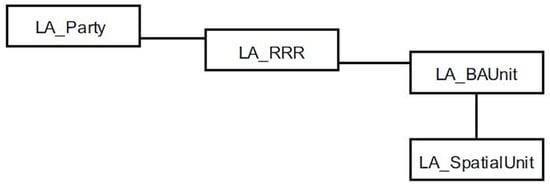
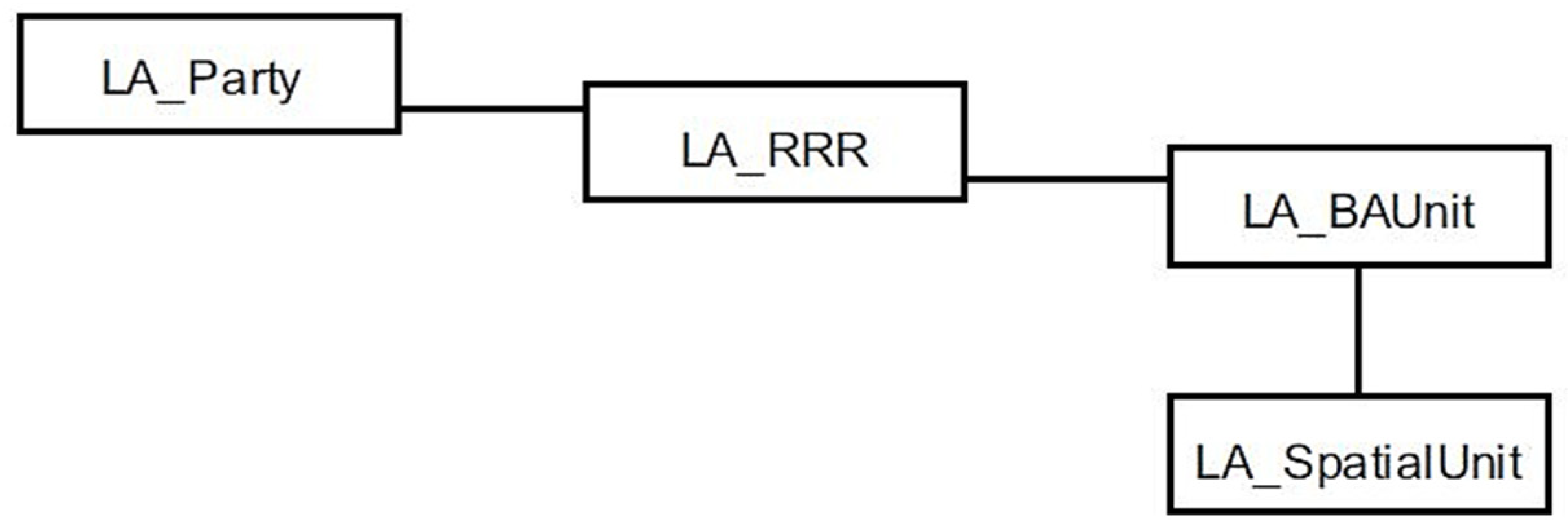
LADM is organized into three packages and one sub-package: party package, administrative package, spatial unit package, and the surveying and representation subpackage of spatial unit package [11]. The core of LADM is based on four basic classes: LA_Party, LA_RRR, LA_BAUnit, and LA_SpatialUnit, see Figure 1. LA_Party is the main class of the party package, which defines the actors such as people or organizations in the land administration. LA_RRR is used for modeling RRRs (hence the class name “LA_RRR”) in which e.g., the right may entitle an owner of a property, for certain purposes, to use a range of other owners’ property or facility such as way, bridge, and lines. LA_BAUnit are basic administrative units that can be subdivided into several spatial units belonging to a party with the same LA_RRRs.
Figure 1.
The four basic classes of the core land administration domain model (LADM) ([11], p. 9).
As for the spatial unit package, it includes two main classes relevant to this study, namely LA_SpatialUnit and LA_LegalSpaceBuildingUnit. LA_SpatialUnit contains various spatial representations of ownership interests and it can be grouped into LA_SpatialUnitGroup or split into sub-spatial units. As a bridge to connect LADM with CityGML 3.0, LA_LegalSpaceBuildingUnit defines the building unit with legal spaces that may be used for different purposes (e.g., living or commercial) where a building or a part of it is not equivalent to the physical separation. It has to be noted that LADM describes the legal space or volume covered by the RRR, not the physical building or construction space or volume, but LA_SpatialUnit can be used to link the legal space to physical elements.
The last package is the surveying and representation subpackage that is mainly used for surveying spatial sources and representing geometries and topology [25]. The three key elements LA_Point, LA_BoundaryFaceString, and LA_BoundaryFace can be used for modeling boundaries of spatial units based on the different demands. For example, 2D spatial units like land parcels and 3D spatial units like 3D properties can be represented by LA_BoundaryFaceString and LA_BoundaryFace, respectively [11]. LA_Point represents a position observed by terrestrial surveying.
2.3. Models of 3D Physical Space
2.3.1. Building Information Models (BIM)
BIM is a digital representation of buildings and building components in the lifecycle phases [8]. Moreover, BIM is not only a model or tool, but also a process and technology. BIM can support and improve various business practices for different actors, such as improving collaboration, increasing building performance and quality, synchronizing the planning and procurement of design and construction, improving energy efficiency and sustainability, and reducing time and cost [8,26]. ISO has recently published the ISO 19650:2018 series Part 1—Concepts and principles and Part 2—Delivery phase of the assets [27,28]; while Part 3—Operational phase of assets, Part 4—Information exchange, and Part 5—security-minded approach to information management are under development.
BuildingSMART has developed international open standards for the building industry worldwide, such as IFC, International Framework for Dictionaries (IFD), and Information Delivery Manual (IDM)/Model View Definitions (MVD). These open standards for BIM specify the terminology, identify the process, and enable digital storage for interoperability [29]. IFC is an open international standard for BIM, which can exchange and share information among software applications by many different stakeholders [9]. It can describe installation, construction, and operation in a logical way. The IFC standard ISO 16739-1:2018 (previous version ISO 16739:2013) defines required data for buildings over the life cycle, which is represented as an EXPRESS schema and an XML schema (XSD) [9]. It can be encoded in various electronic formats, for example STEP Physical File (SPF), XML, and JSON. The IFC standard decomposes the data model in a completely hierarchical structure. IfcRoot is the most abstract superclass containing three major classes IfcPropertyDefinition, IfcRelationship, and IfcObjectDefinition, where the last one has a grand subtype IfcProduct [9]. IfcProduct is an abstract class that represents spatial and physical context covered in the subclasses IfcSpatialStructureElement or IfcElement, respectively. In our study we use the class IfcSpace for defining the cadastral boundaries, where IfcSpace is a subclass to IfcSpatialStructureElement.
In the IFC standard, spaces are defined as areas or volumes bounded actually or theoretically that provide for certain functions within a building [30]. Space boundaries are virtual objects used to calculate quantities for analysis related to spaces or rooms in buildings, including three levels: 1st Level Space Boundaries, 2nd Level Space Boundaries, and 3rd Level Space Boundaries. Usually, IfcSpace and IfcSlab (subtype of IfcBuildingElement) are two common element types used to convert simple geometries in IFC to equivalent geometries in CityGML.
Nowadays, BIM/IFC has been used as geometry model and integrated with 3D cadastre. Generally, there are two methods to integrate BIM with 3D cadastral information: direct and indirect. Direct method is usually to generate 3D cadastral model by using BIM/IFC according to architecture plans, while indirect method utilizes existing BIM/IFC model as physical model to integrate cadastral information or legal model. For instance, Atazadeh et al. [31] explored the feasibility of using BIM to model the boundaries of ownership spaces inside buildings directly and identified relevant geometric and semantic IFC entities. They developed and implemented a BIM prototype that demonstrated the advantages of BIM to represent different types of building ownership boundaries compared with 2D plans of subdivision. However, the authors pointed out that BIM models are usually prepared by architects in the design phase, which could be different from the real building ownership boundaries after construction in practice. Further research of Atazadeh et al. [32] developed BIM-based queries for interrogating questions about the legal ownership of properties inside multistory buildings. On the other hand, Oldfield et al. [33] defined requirements, modelled a collaborative process through the IDM, and mapped the data model between the LADM and IFC by using an indirect method. The IfcSpace entity was mapped to LA_SpatialUnit in LADM. They suggested that the IFC models, as physical models to generate 3D cadastre, could be manually developed and tailored to Land Registry requirements.
2.3.2. City Models
The CityGML specification is commonly used to represent semantic and geometric properties of 3D city models for several applications such as urban planning, 3D cadastre, facility management, and environmental simulations [34,35,36]. CityGML is an XML-based open standardized geometry model, which supports storages and exchange of 3D spatial data effectively [35]. There are five defined levels of detail (LOD) in current CityGML 2.0 from LOD0 (2D footprint representations) to LOD4 (interior and exterior architectural models), which multiply represents relations of objects. However, CityGML is designed to keep a minimum number of common features with a slim core data model, which means that for some specific application fields additional information is required and needs to be modelled [37]. To support additional requirements by certain use cases CityGML 2.0 developed a built-in mechanism application domain extension (ADE) [38], which can be utilized for cadastral applications [10]. For example, Góźdź et al. [12] elaborated object relationships from the legal and physical world as well as building geometry in LOD1 for visualization of legal spaces. Because it is difficult to describe the legal information about spatial objects in CityGML 2.0, a CityGML-LADM ADE model was implemented to provide relations between spatial objects from legal and physical world.
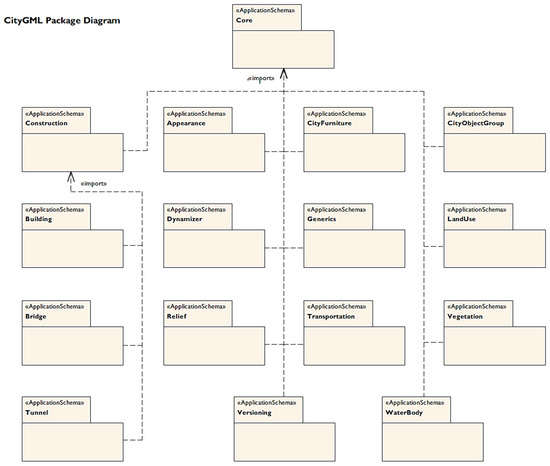
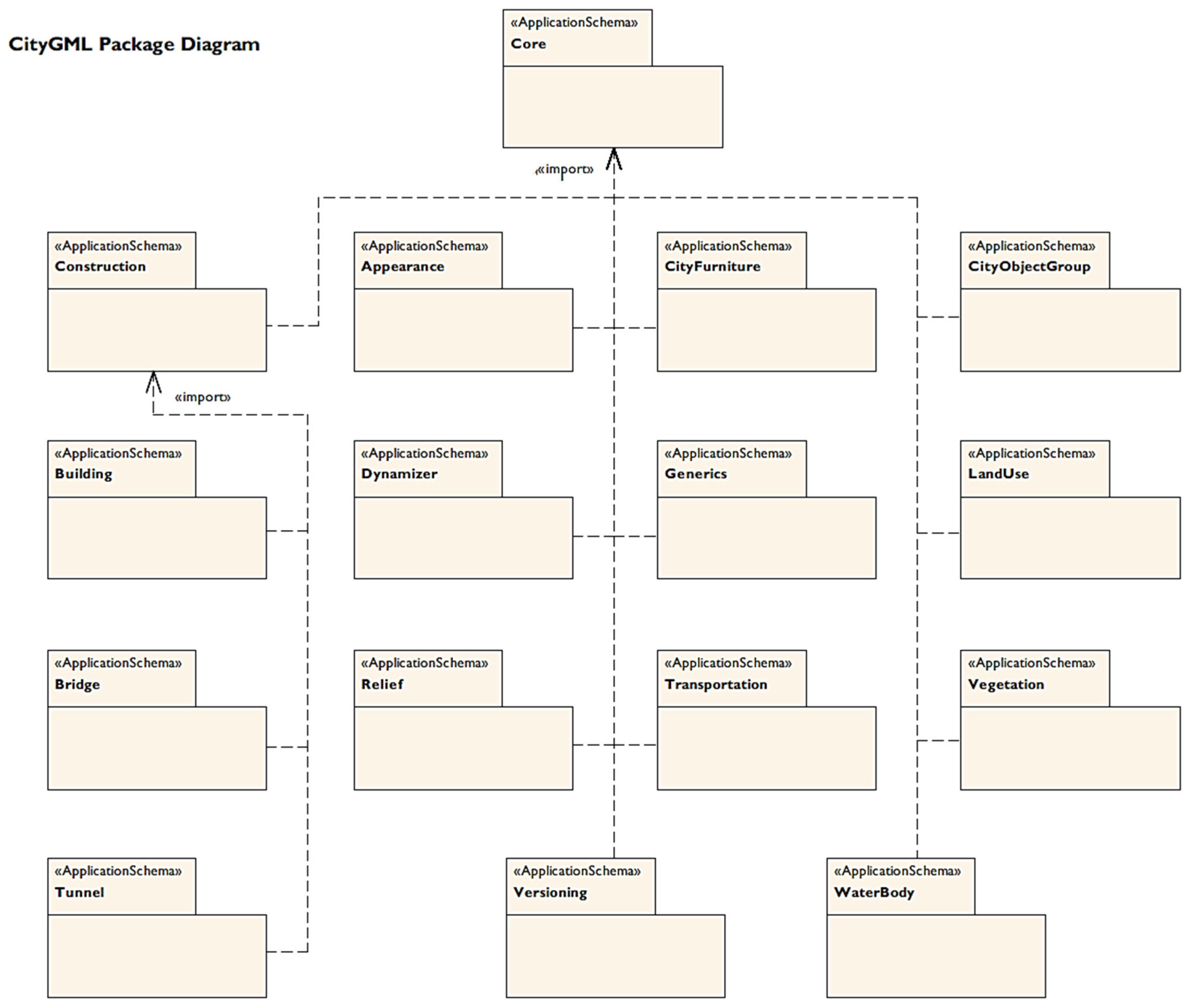
To better interoperate with other standards like IFC, LADM, and IndoorGML a new version of CityGML is proposed denoted as CityGML 3.0 [10]; Figure 2 illustrates the CityGML 3.0 package diagram and their relationships. All data models and XML Schemas have been derived from UML diagrams.
Figure 2.
CityGML 3.0 package diagram and their relationships [39].
Compared to CityGML 2.0, the LODs have been revised, which removes LOD4 and only LOD0 to LOD3 remains. The outside shell of a building and the interior structure are possible modelled and represented in different LOD [10]. Moreover, the Core model has been revised to implement the new LOD concept and represents spatial information semantically and thematically using two pivotal abstract classes AbstractSpace and AbstractSpaceBoundary. Of major interest to 3D cadastre management is the class AbstractLogicalSpace that enables modelling of logical spaces, i.e., spaces that not necessarily have physical boundaries such as legal spaces in a cadastre. Of further interest to this study is the new CityGML module construction which defines common concepts of man-made constructions such as buildings, bridges, tunnels, and other constructions. The construction module defines an AbstractConstructiveElement to facilitate IFC to CityGML conversions by enabling mapping of constructive elements from IFC classes into CityGML, for example IfcWall, IfcRoof, and IfcSlab [10]. However, the final version of CityGML 3.0 has not been adopted (in October 2019).
2.3.3. Converting BIM Data to 3D City Model Data
BIM and 3D GIS are designed and developed independently to serve different purposes and to be used in different tools. BIM is a symbolic representation and more focuses on the building element properties with details rather than abstract spatial entities. While a 3D city model can model large scale data up to entire cities, even countries. Because the cadastre is also used in urban planning and management, there are limitations of BIM for visualizing and analyzing the 3D cadastre on city level. At the same time, there are some overlap between BIM and 3D city models because they specify semantic data and both domains model buildings and constructions [40]. Thus, the integration of BIM and 3D city model is mutually beneficial for comprehensive 3D city modelling. The conversion of BIM data to city model data has shown a growing interest in different applications such as urban planning, construction, facilitate management, building permits, and 3D cadastre [36,41,42,43,44]. Donkers et al. [45] addressed conversion from geometry aspects and developed an automatic conversion method from IFC to CityGML LOD3. Sun et al. [36] proposed a methodology to formalize the geometric aspects of the integration of BIM data into 3D city models based on the developed modelling guidelines.
However, because of the different data structures, converting BIM to 3D city models without losing data is extremely difficult. Stouffs et al. [46] defined a triple graph grammar (TGG) to formally relate IFC and CityGML semantically and geometrically. In their approach, they are using a CityGML ADE to minimize the information loss in the conversion.
Some implementations for converting BIM to CityGML models are available, for example IfcExplorer CityGML Export (IFCExplorer 2018, an extension to the open source BIMserver) and Feature Manipulation Engine (FME, an extract, transform, and load tool) from SAFE Software. Many studies implemented models conversion by using FME framework [36,44,47,48].
According to the literature review, those studies have proposed the registration and visualization of 3D cadastre with different physical models. However, those research results in general did not provide details about how to utilize physical models in representing and visualizing cadastral information through different organizations in terms of legal and practical perspectives.
3. A General Framework for Integrating Cadastral Information with BIM and 3D GIS
Today the cadastral surveying units, AEC companies and city-surveying units share information in the property formation and management process. However, this information is, at least in Sweden, still often in paper or PDF-format. In case there are digital data, they are often in 2D (e.g., 2D index maps, section drawings, etc.). There is a trend that these organizations use more international standards for their data and also that 3D standards such as IFC and CityGML are supported. Below we propose a general framework for the integration of cadastral information with BIM and GIS to support information sharing between these organizations in practice. In Section 3.1, we formulate the requirements of such a framework including legal perspective, reference system, and visualization requirements. Then in Section 3.2, we describe the general framework, which we implement and evaluate in a case study as described in Section 4.
3.1. Requirements from 3D Cadastral Perspectives of the General Framework
In this section, we formulate the requirements from legal and technical perspectives that are important from 3D cadastral perspectives. According to van Oosterom and Shojaei et al. [2,16], the perspectives are broken down into six topics as described below.
(1) Organizational perspective
In a life-cycle project, the implementation of each phase involves many organizations, which requires close coordination between various units. It is important to clearly define the functions and responsibilities of each organization, so that they can perform their duties and collaborate with each other. The aim of this framework is to facilitate digital data exchange between the cadastral surveying units, AEC companies, and city-surveying units. In order to simplify and optimize the procedures of 3D cadastre, the cadastral units should guide and adjust other units for improving communications and efficiency.
(2) Legal perspective
The legal perspective plays a main and basic role in real 3D cadastral information systems and applications. Kitsakis et al. [49] presented the different legal concepts regarding 3D real property in the examined countries and the characteristic features of 3D cadastre within each country’s legal and cadastral framework, based on their national experiences. According to their research, 3D cadastre requires to [49]:
- Re-define real property in 3D space using unambiguous 3D terminology;
- Establish legal instruments to subdivide;
- Consolidate and manage 3D real property;
- Introduce 3D Public Law Regulations (PLR);
- Amend cadastral survey procedures and data recording to incorporate 3D characteristics of real property;
- Transit current 2D real property to 3D.
It is important that these requirements are supported in our framework.
(3) Coordinate reference system and height system
The reference system of 2D cadastral mapping usually uses a national reference spatial coordinate system. In many European countries, the international (continental) and global reference spatial coordinate systems are becoming more important to facilitate spatial data exchange at the international level [4].
3D cadastre includes 3D real property units that are bounded horizontally and vertically as space volumes. In other words, the 3D (X, Y, Z) coordinate system should be provided and used in 3D cadastral systems with planar coordinates in the national planar system, and absolute and relative heights in the national height reference system [4]. To serve various needs, different height information should be measured by land surveyors and provide both in current 2D dossiers and 3D cadastral models. Furthermore, to satisfy the accurate quality of 3D cadastre, the height requirements may be re-defined.
(4) Data standards
Current registration has limitations in representing the actual extent of complicated 3D property units especially in complex building situations. With the development and advantages of 3D physical models, it is efficient and accurate to integrate legal and physical models in order to improve the representation and visualization of the 3D cadastre [50]. Therefore, the data standard of 3D cadastral models should adopt both legal and physical model standards. It is essential and beneficial that open standards are used for all of these models.
(5) Geometry
The 3D cadastral data model is an integrated model, which should represent its geometry legally and physically. A boundary representing the limit of an entity is most commonly used in the context of geometry. In 3D cadastral geometry, a closed volume is used to represent a legal space and should be physically bounded with precise property boundaries and heights. Note that the 3D physical object is usually smaller than the legal space related to this object. It is important to realize that the volumes should include both physical construction parts and associated legal spaces in the air and underground, containing for example protruding building parts.
(6) Users and user requirements
Various users and their specific needs are the motivation to build a 3D cadastral model. Pouliot et al. [51] summarized the user of 3D cadastre, and user requirements as given in Table 1; requirements that we adopt to our framework.
Table 1.
Users and user requirements [51].
3.2. Overview of the General Framework
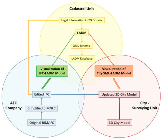
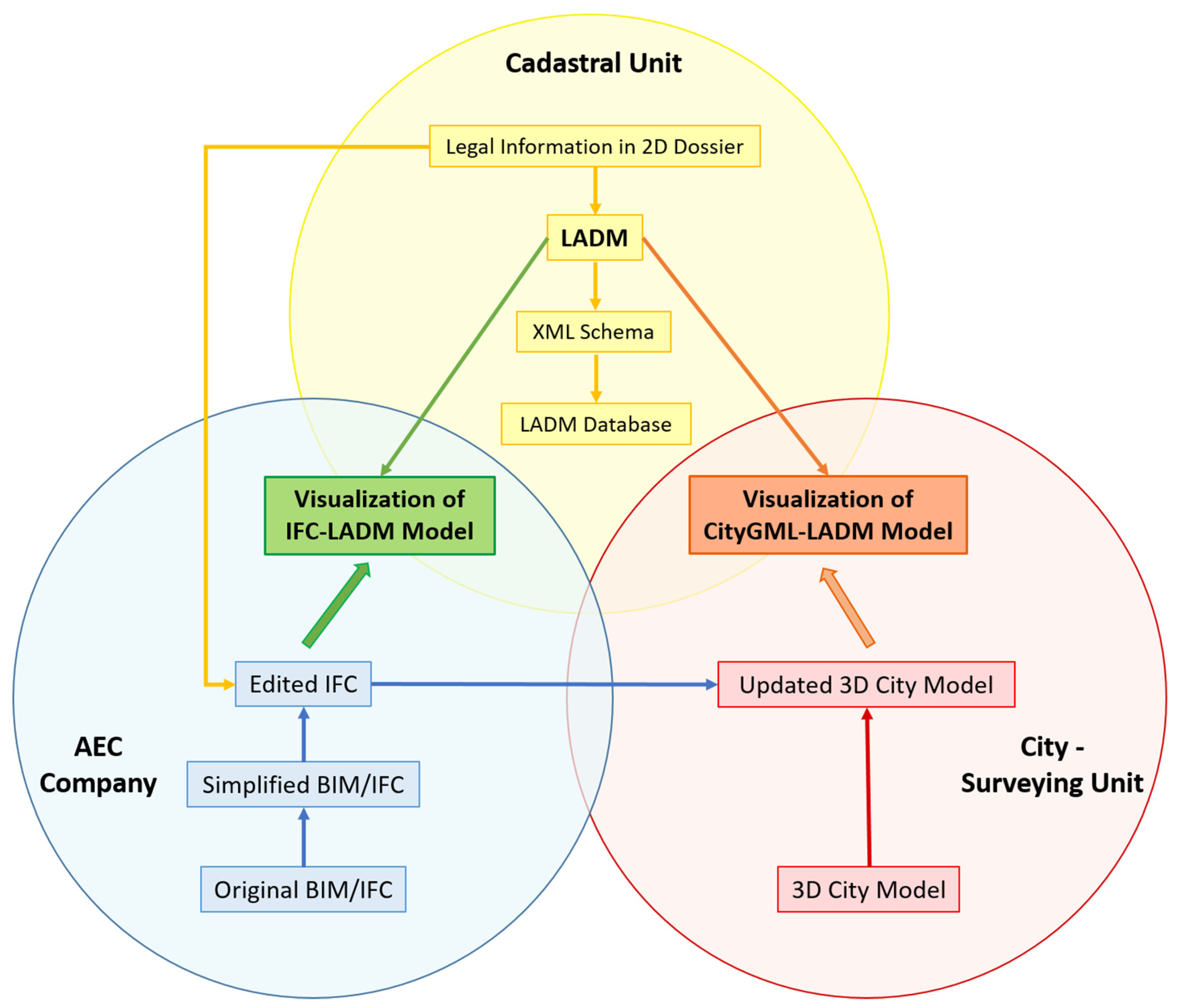
In this paper, we propose a vision of the general framework for integrating 3D cadastre with BIM and GIS in practice (Figure 3) that supports the requirements above. We adopt the LADM standard for cadastral information, and the IFC and CityGML standards for physical models; they are all open standards as requested.
Figure 3.
The general framework for integrating cadastre with building information model (BIM) and geographic information system (GIS).
The LADM database will act as the cadastral database to fulfill the legal requirements. To represent legal spaces physically, an IFC model is used as a bridge to link the physical spaces to LADM. IFC also supports representations of closed volumes which is a geometric requirement. If the original IFC models from AEC Companies are as-built models, simplification of pre-processing is needed to delete unnecessary building elements for clearly identifying boundaries and reducing model size. The edited IFC model, on one hand will integrate LADM to generate an IFC-LADM model for cadastral visualization on building level to satisfy users’ requirements. On the other hand, to visualize 3D cadastre on the city level, the IFC model will be converted to CityGML format. Note that the transfer of coordinate systems should be unified in this conversion process. Then, the CityGML model will be integrated with LADM to create a CityGML-LADM model used to e.g., identify 3D properties on city level and to locate and compare them (user requirements in Table 1).
To facilitate the general framework, the following basic steps are required:
- (1)
- Creating a LADM file containing the legal attribute information;
- (2)
- Specifying 3D property boundaries in IFC;
- (3)
- Connecting and visualizing IFC and LADM at building level;
- (4)
- Converting IFC to CityGML data;
- (5)
- Connecting and visualizing CityGML and LADM at city level;
In the case study below, we implement all of these steps as a proof of concept of our general framework.
4. Methodology and Case Study
In this section we describe a methodology to realize the general framework in Figure 3. At the same time we exemplify the steps by using a case study. The scripts are released https://github.com/TestbedLU/Article-LADM-IFC-CityGML under the open source license Berkley Software Distribution BSD https://opensource.org/licenses/BSD-3-Clause. We are not allowed to provide some of the data, e.g., the BIM model.
4.1. Study Area and Data in the Case Study
A newly built multistore building located in Malmö, Sweden, called Multihuset, is used as a case study of the general framework. Multihuset is a six-storey building that comprises approximately 19,800 square meters. The building is complex and built a large parking garage in the center and surrounding with varied functional content including housing, offices, health center, childcare center, grocery store, pharmacy, preschool, and café. Multihuset is divided into two property units: Bryggan 1 containing housing and Bryggan 2 containing other functions: grocery store, health center, P-house, preschool, office, and pharmacy. In this case study, we only study the physical extent of the 3D property units on the fifth story.
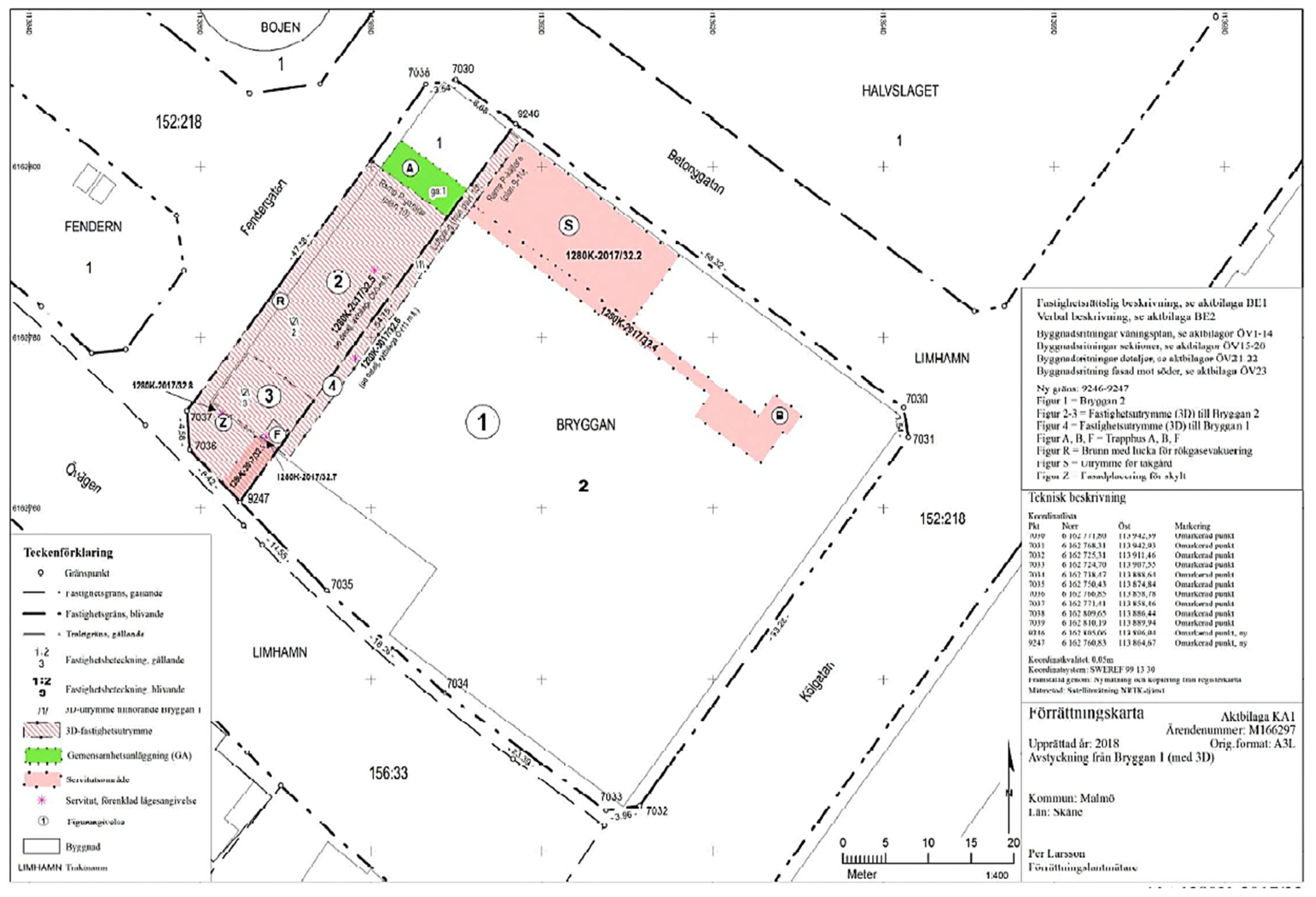
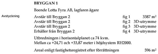
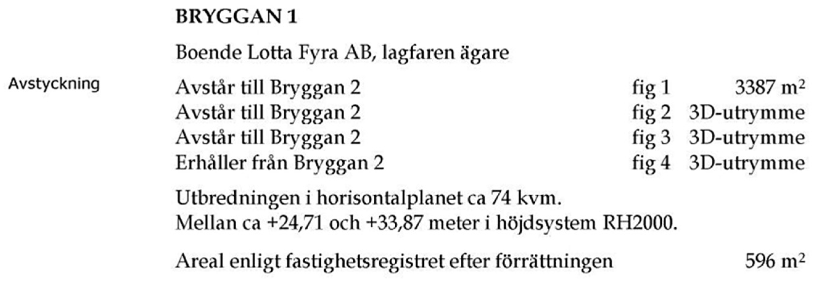
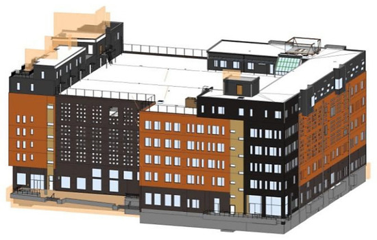
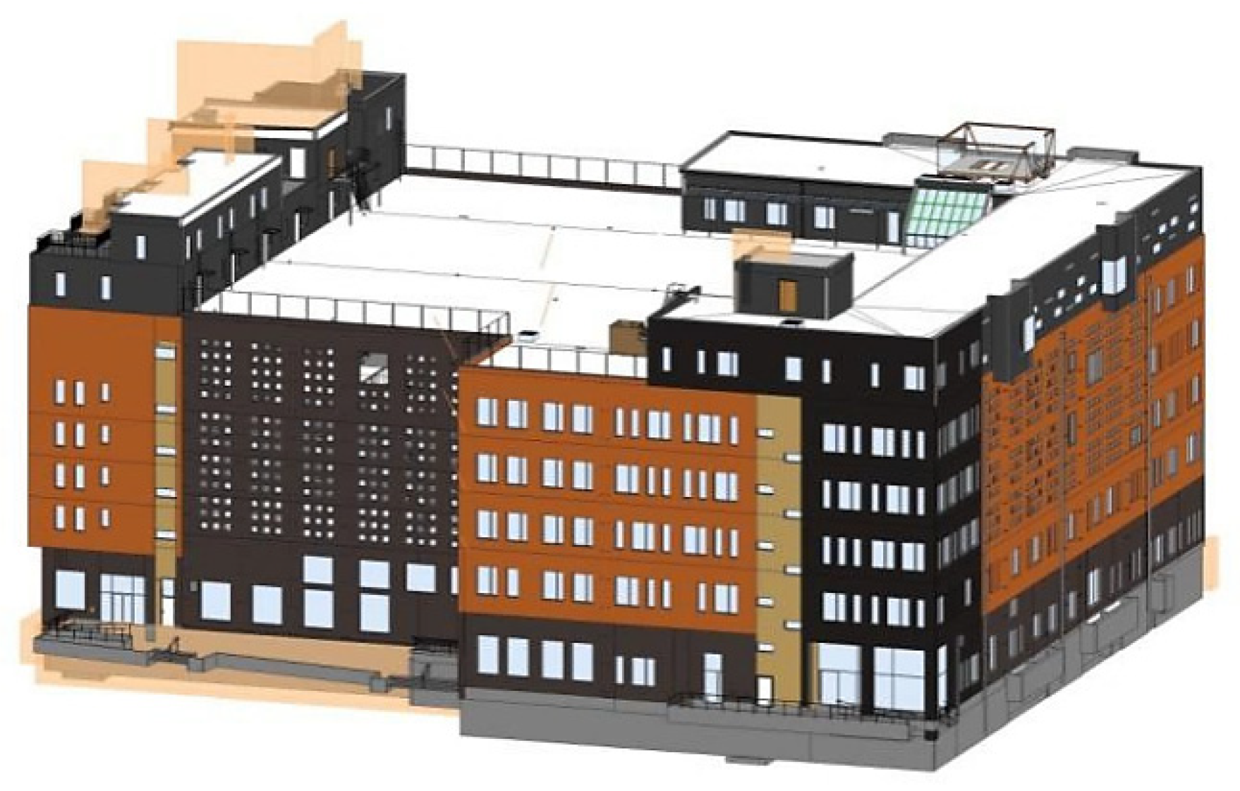
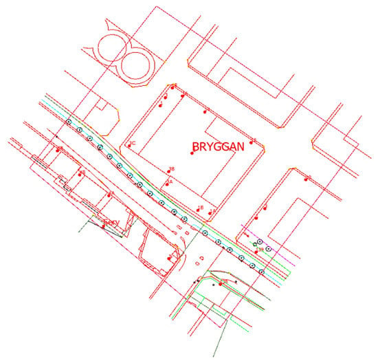
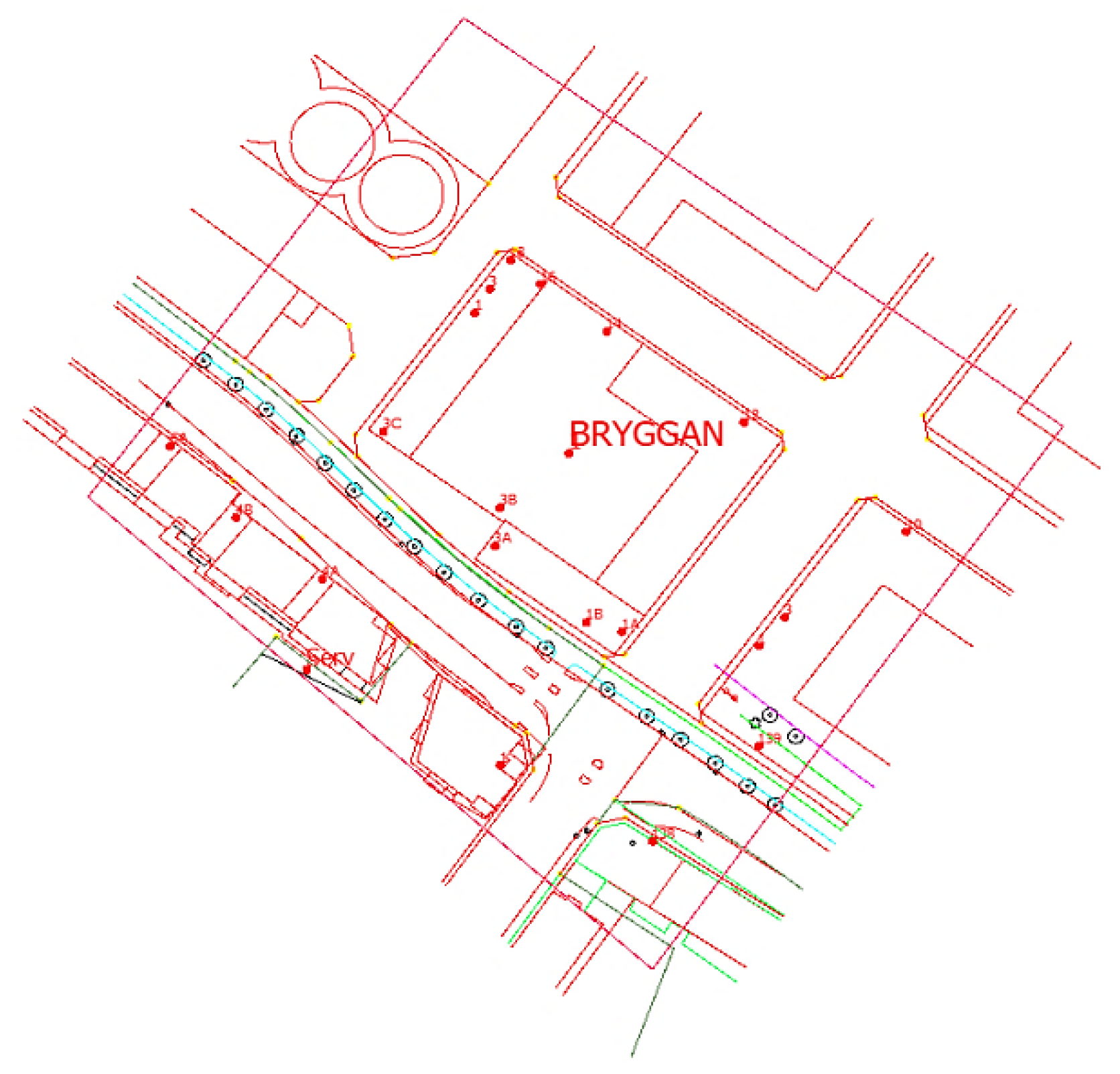
The legal information of the 3D registered property of Multihuset is stored in 2D documents including an index map (Figure 4) with coordinates of space boundaries (reference system is SWEREF99 13 30), cadastral dossiers including verbal descriptions of boundaries, property areas, heights in the national reference system height system RH2000 (Figure 5) and construction plans. Figure 5 gives a brief description of the location in height between level around “+ 24.71 meter” and “+ 33.87 meter” (“ca” means around). A subset of the 3D city model in LOD 2 over Malmö was obtained from Malmö municipality. The 3D city model was delivered in Trimble SketchUp format and includes the area around the building Multihuset. Figure 6 shows the BIM model (from a late stage in the construction process, almost a completed relational handling BIM model) which was delivered in IFC 2*3 format from NCC Company. Finally, Figure 7 shows the 2D cadastral index map.
Figure 4.
Cadastral map of Multihuset, Malmö, Sweden (Source: Malmö municipality).
Figure 5.
Parts of textual 3D information (in Swedish) in Multihuset cadastral document (Source: Malmö municipality).
Figure 6.
Industry Foundation Classes (IFC) model shown in Revit (Source: NCC Company).
Figure 7.
2D cadastral index map (Source: Malmö municipality). Note that this index map does not show the subdivision of the property Bryggan.
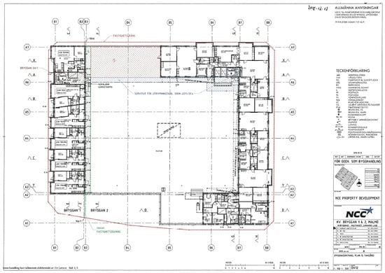
Figure 8 shows the construction map of the fifth storey in Multihuset (marked as "Plan 15" in the cadastral dossiers). Green lines are the property boundaries that divide this floor into two property units: Bryggan 1 and Bryggan 2. Note that the boundary lines in different floors are not the same and not completely following building elements like walls. Red areas marked with Ⓢ are for the use of easement, while blue areas are easements for evacuation route.
Figure 8.
Example of computer aided design (CAD) construction plans in Multihuset as part of the actual property formation dossier, green lines representing property boundaries (Source: NCC Company).
4.2. Step 1: Create a LADM File Containing the Legal Attribute Information
In a future scenario, the cadastral unit will store the legal attribute information in a LADM model directly in the property formation process. However, in this case study we extract information from a standard cadastral dossier to fill information into the LADM model.
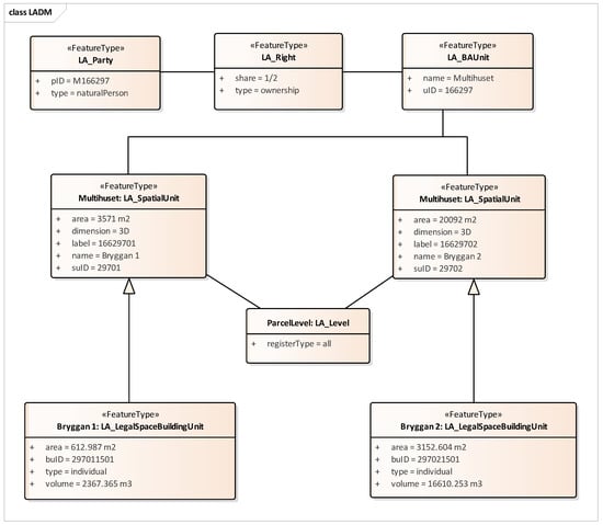
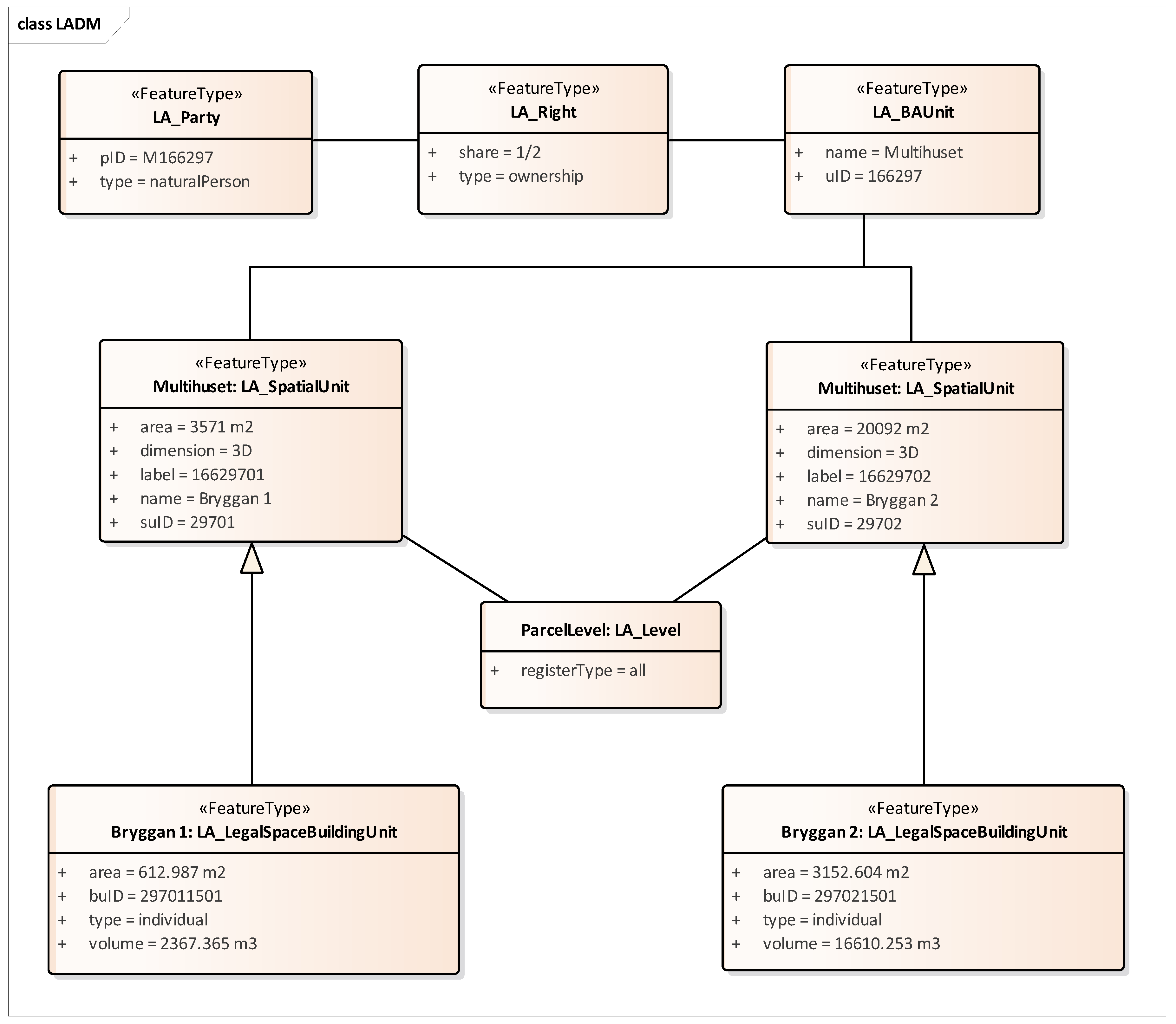
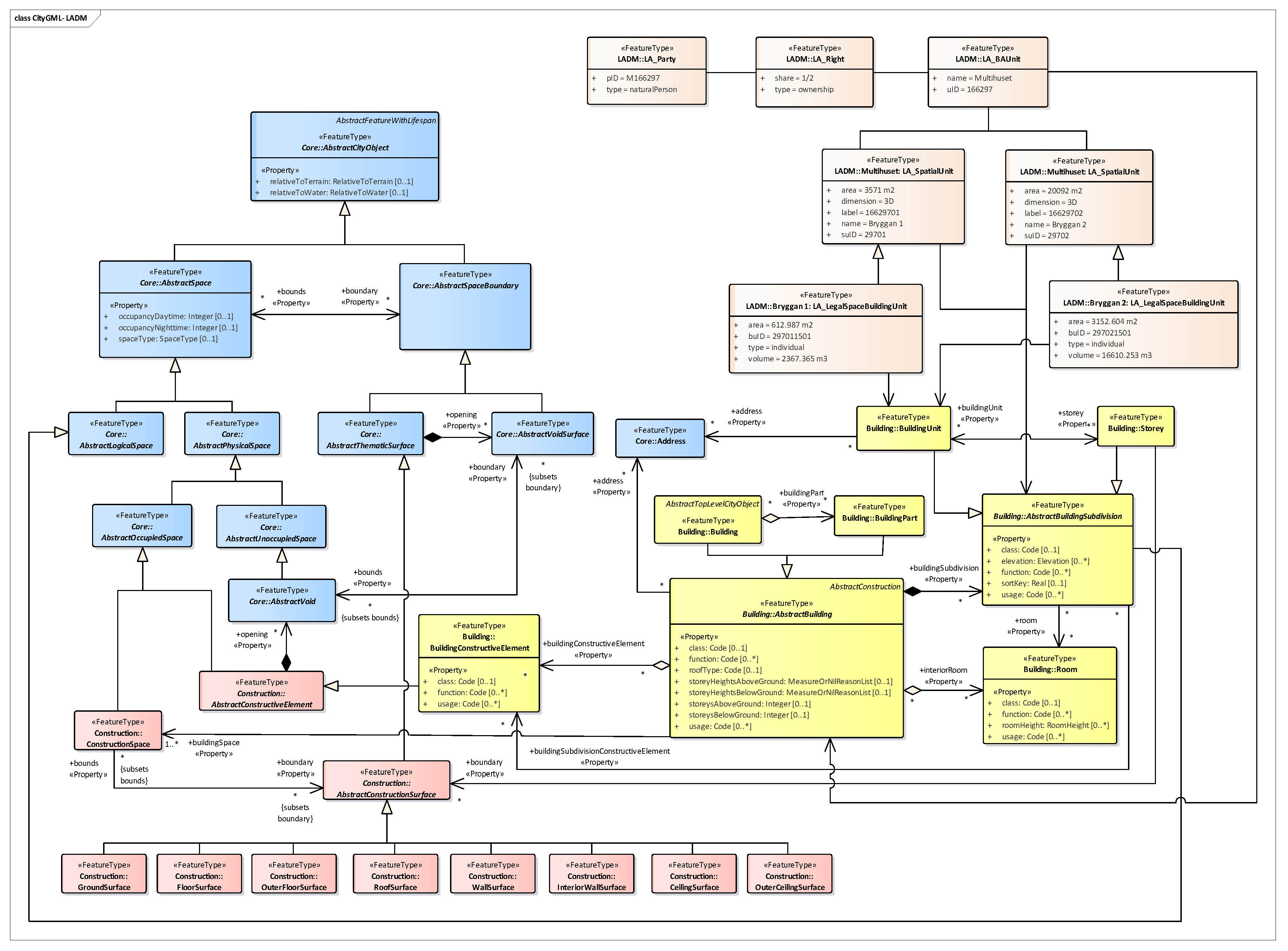
According to the construction map and legal information, we created a LADM UML using the software Enterprise Architect (Sparx Systems, Creswick, Australia). Figure 9 shows the classes of LADM and their associated relationships. In this study, there were six elements defined in the XSD file, which corresponded to the six classes in the UML diagram of LADM. There were two attributes in the LA_Party class: “pID” (M166297) was the case number saved in the cadastral units; and type was the natural person. Multihuset is the basic administrative unit represented with “uID” (166297) in LA_BAUnit, which was subdivided into two property units Bryggan 1 and Bryggan 2 sharing the right. The LA_SpatialUnit contained various spatial representations and defined the attributes of Bryggan 1 and Bryggan 2 with “suID” (29701 and 29702) respectively. According to the construction maps in cadastral dossiers, each plan had different property boundaries. The specialization LA_LegalSpaceBuildingUnit of LA_SpatialUnit defined the legal spaces of Plan 15. Moreover, its attribute “buID” (297011501 and 297021501) inherited from “suID” could be used to link the legal spaces to physical elements, more details shown in Section 4.4 and Section 4.6.
Figure 9.
LADM UML and the associated relationships between the classes.
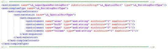
The geometric classes LA_BoundaryFace and LA_BoundaryFaceString were also defined in the XSD file for ensuring the structural integrity, even though there was no geometric attribute involved. Apart from the classes, their corresponding attributes were also generated as sub-elements contained in a "sequence" model group within the definition. As shown in Figure 10, element LA_LegalSpaceBuildingUnit was extracted from the corresponding class in the LADM UML. Its attributes area, “buID”, type, and volume were defined in a "sequence" group.
Figure 10.
Definition of LA_LegalSpaceBuildingUnit within the XSD file.
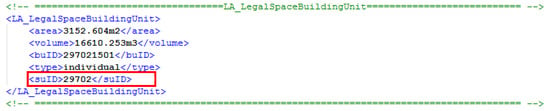
With the XSD file, an XML instance can be generated by using the Liquid Studio (Liquid Technologies, Bradford, UK), in which attributes were assigned according to the information stored in the cadastral dossier. Considering that the relationships among classes cannot be mapped on the XSD file, an extra attribute “foreign key” was added manually as well. As shown in Figure 11, “suID” was a foreign key to connect LA_LegalSpaceBuildingUnit with LA_SpatialUnit. Since the geometry in LADM was not involved in this study, the classes LA_BoundaryFace and LA_BoundaryFaceString were not generated in the XML file.
Figure 11.
Part of a referenced XML document defined LA_LegalSpaceBuildingUnit in LADM.
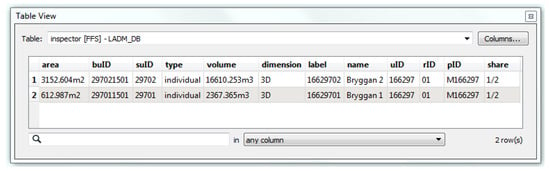
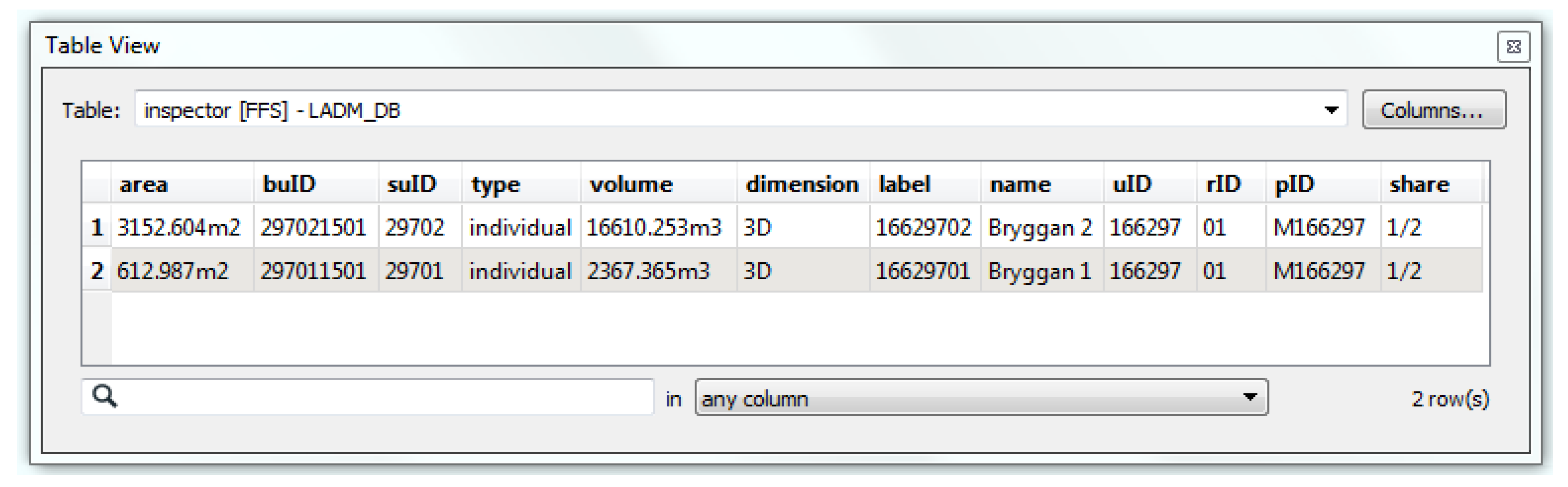
After importing the XML file into FME Workbench (Safe Software, Vancouver, Canada), the elements were matched as corresponding feature types (LA_Party, LA_Right, LA_BAUnit, LA_SpatialUnit and LA_LegalSpaceBuildingUnit). The LADM database, namely LADM_DB was then created by integrating all imported feature types. This database reduced the complexity for combining cadastral information with 3D models to some degree. Figure 12 shows a LADM database that merges all feature types into one table.
Figure 12.
Cadastral information stored in LADM database.
4.3. Step 2: Specify 3D Property Boundaries in IFC
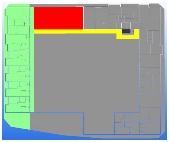
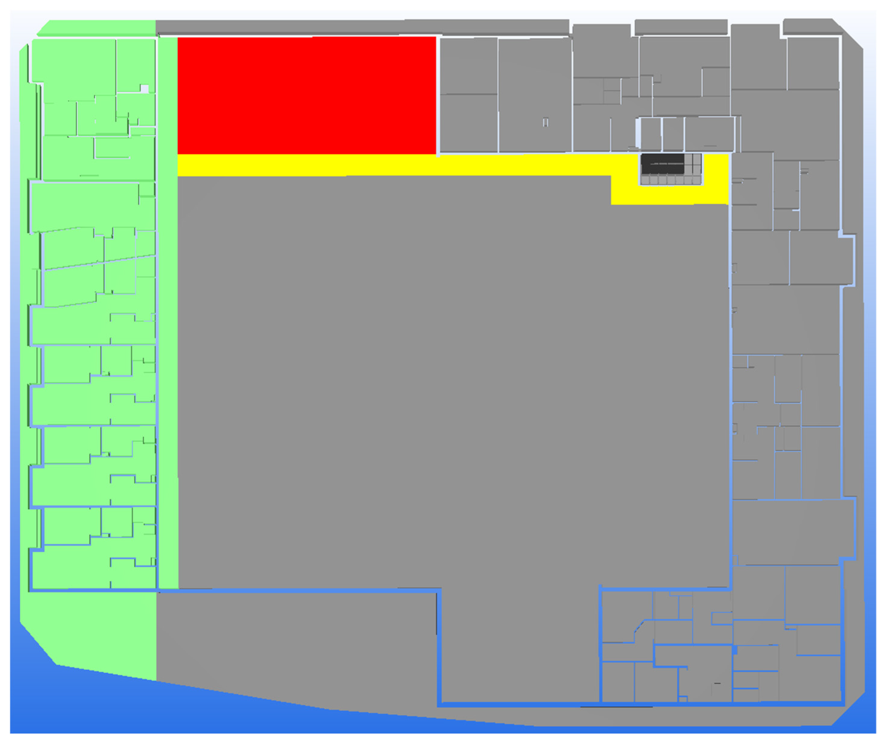
To specify the 3D property boundaries in the IFC model, the original model needed to be simplified and then appended with space elements that describe the extent of the 3D property units. In this study, the property boundaries include both outside property lines surrounding the building and inside property lines dividing the building into two property units. Each property unit should contain the 3D volumes’ both physical construction parts and associated legal spaces above ground and underground. However, the property boundaries for each plan and the heights were not unique because of the construction. Thus, it was necessary for manual corrections in Revit when separating spaces accurately. Related to the 3D property units Bryggan 1 and Bryggan 2, Ifczone elements were generated by grouping spaces. Both IfcSpace and IfcZone of IFC 2*3 format were exported from Revit in order to connect to the LADM database and visualize the integrated cadastral model at building level. Figure 13 illustrated the IFC spaces model of Plan 15 defining 3D property boundaries both inside and outside the building, corresponding to Figure 8.
Figure 13.
IFC spaces model of Plan 15 (corresponding to Figure 8), defining 3D property boundaries both inside and outside the building. The green areas for Bryggan 1 and the grey areas for Bryggan 2 including red areas (the use of easements) and yellow areas (easements for evacuation route).
4.4. Step 3: Connect and Visualize IFC and LADM at Building Level
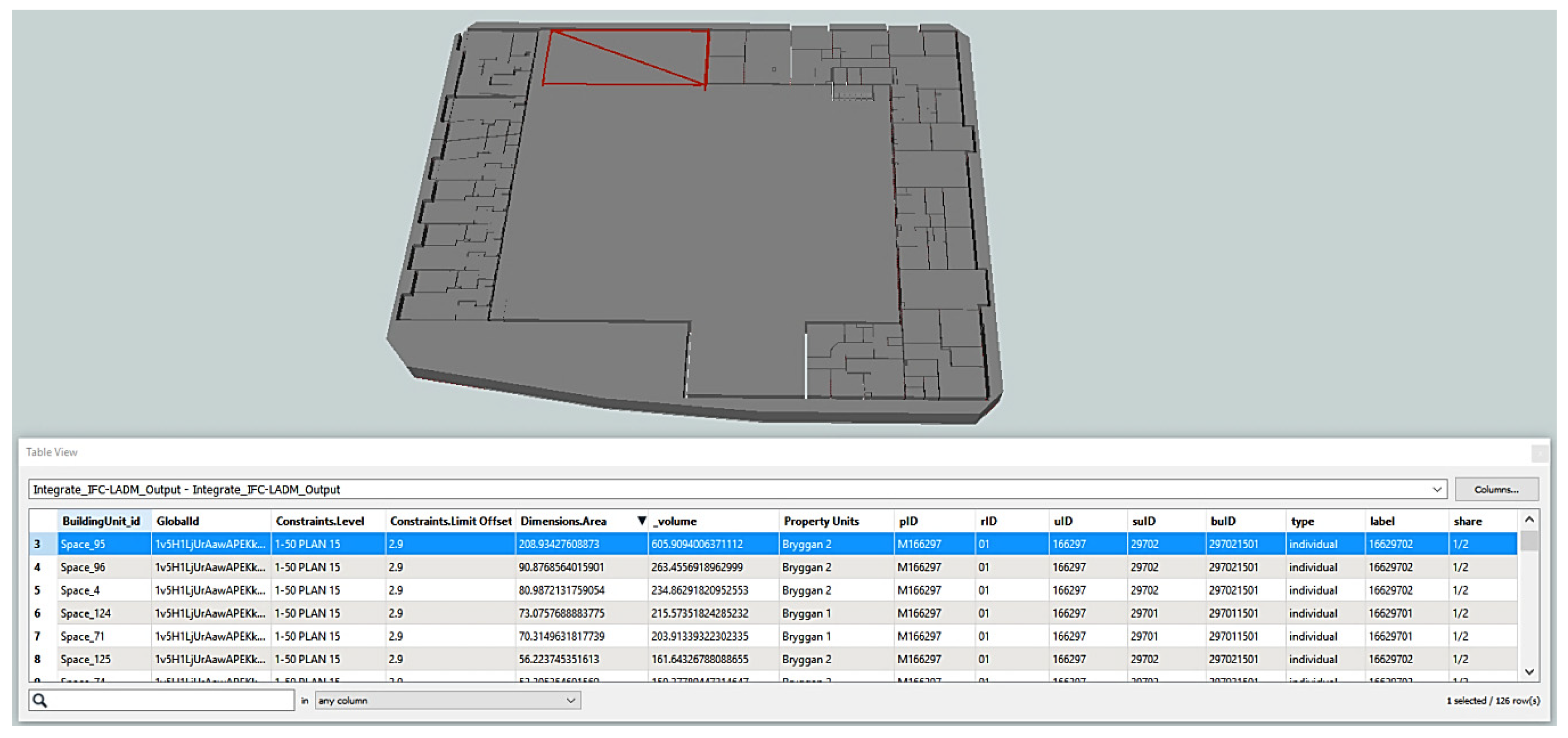
The IFC model and LADM database were integrated via the IfcSpace entity in FME. Because there is no geometric information stored in the digital cadastral database, only attributes were used to connect IFC and LADM. Related to the LADM database shown in Figure 12, the attribute name (Bryggan 1 and Bryggan 2) was chosen as the key to link with the attribute IfcZone in the IFC model. However, FME does not support to read and link IfcZone directly. Thus, IfcSpace had to be managed as property units and then filtered into the two groups Bryggan 1 and Bryggan 2 for integration with LADM. Figure 14 shows the integrated IFC-LADM model with the table of attributes.
Figure 14.
The integrated IFC-LADM model with the table of attributes.
4.5. Step 4: Convert IFC to CityGML Data
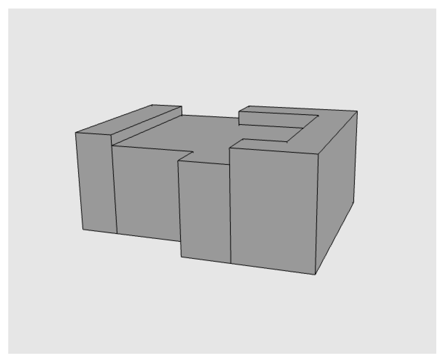
To simulate a situation where an existing 3D city model is updated with a newly constructed building and integrated with cadastral data, the city model first had to be imported into FME and converted from Trimble SketchUp format to CityGML 3.0 geometries (GML 3.2.1). The geometry conversion was performed with a GeometryExtractor transformer. To update the 3D city model with the building Multihuset, the IFC model was first converted to a LOD2 CityGML 3.0 building model. This conversion was done by extracting the three main external roof surfaces (IfcSlab elements) of the building and creating wall surfaces from these roof surfaces down to ground level with the method used in [44]. This resulted in the LOD2 CityGML 3.0 building model in Figure 15 that was used to update the 3D city model.
Figure 15.
LOD2 CityGML 3.0 building model of Multihuset (cf. IFC model in Figure 13).
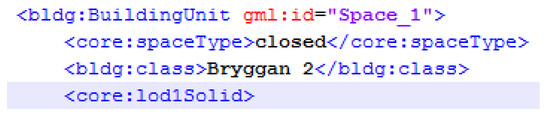
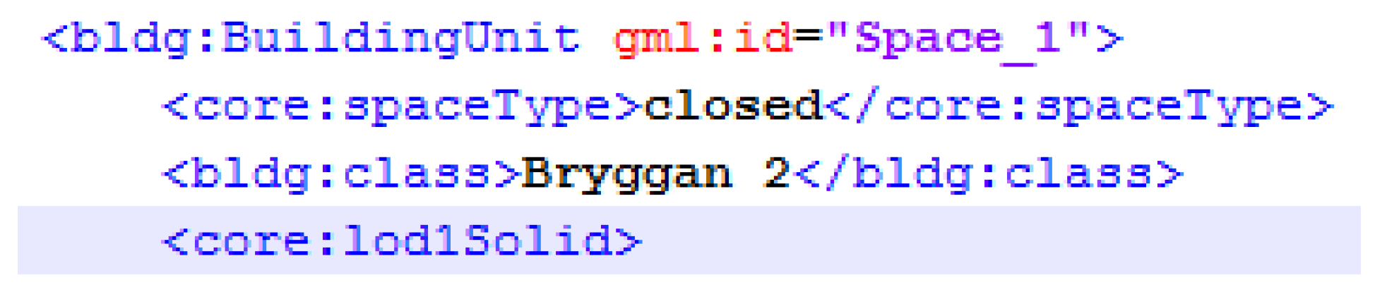
To convert the cadastral data from IFC to CityGML 3.0, the IfcSpace elements representing legal spaces (described in Section 4.3) were imported to FME and the geometries were converted to solid GML 3.2.1 geometries (LOD1) with the GeometryExtractor transformer. A logical space in CityGML 3.0 is an abstract superclass (AbstractLogicalSpace) in the core module, which means that no logical space elements can be directly created. In this study we modeled the legal spaces with the CityGML 3.0 class BuildingUnit, which is a subclass to AbstractBuildingSubdivision, in the Building module (see Section 4.6 for more details). The attribute gml:id that was derived from the IfcSpace element in the IFC file was used as unique identifier for the individual legal spaces and the attribute class was used to state which cadastral unit (Bryggan 1 or Bryggan 2) a legal space belongs to (See Figure 16).
Figure 16.
Part of the CityGML 3.0 file illustrating how the BuildingUnit (logical space) with ID “Space_1” belonging to cadastral unit “Bryggan 2” is modeled.
To enable searches on cadastral unit level the class CityObjectGroup (from the CityObjectGroup module in CityGML 3.0) was utilized. A CityObjectGroup enables grouping of objects, in this case legal spaces belonging to the same cadastral unit, and two groups were created: Bryggan 1 and Bryggan 2. A CityObjectGroup includes the links to all legal spaces (gml:id) that belongs to a given group but no geometries. Finally, all cadastral data were added to the CityGML 3.0 file to integrate it with the 3D city model.
4.6. Step 5: Connect and Visualize CityGML and LADM at City Level
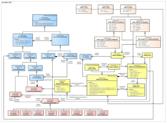
According to the new functionalities of CityGML 3.0, we first created a CityGML UML diagram with new Core, Building and Construction modules and then connected with the LADM UML (Figure 9). Figure 17 shows the UML diagram for integration of CityGML 3.0 with LADM at the conceptual level, where the super class AbstractBuilding is associated with the superclass LA_BAUnit from LADM. In the new Core model, two pivotal abstract classes Space and SpaceBoundary can model all spatial representations [10]. The class AbstractLogicalSpace that can be used to define spaces according to legal considerations instead of physical objects. In addition, LA_SpatialUnit is associated with AbstractBuildingSubdivision (the subclass of AbstractLogicalSpace) that represents BuildingUnit e.g., apartments and public spaces. Storey is also taken as a logical subdivision because of the vaguely description of slabs. Considering that there is only one storey involved in this study, LA_LegalSpaceBuildingUnit is associated with BuildingUnit.
Figure 17.
The Unified Modeling Language (UML) diagram for integration of CityGML 3.0 with LADM.
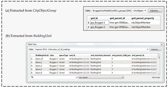
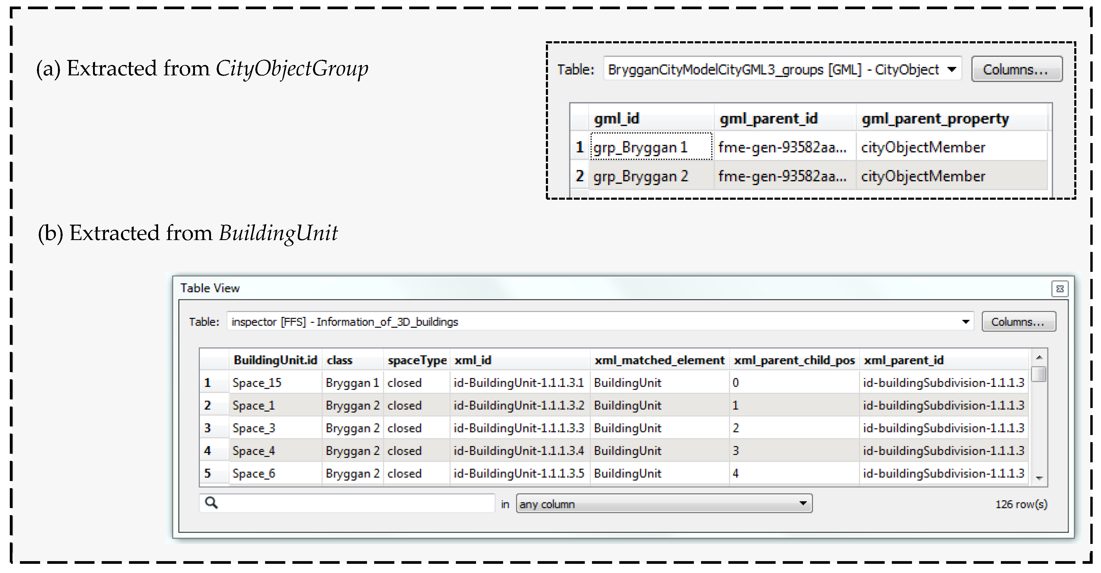
CityGML 3.0 and LADM can be integrated from two aspects; geometric aspect and attribute aspect. For this study, the approach for combing these two standards relies on the attribute value since there is no geometric information stored in the digital cadastral database. Figure 18 shows the attribute information extracted from CityGML 3.0 where the BuildingUnit.id was derived from the gml_id of BuildingUnit automatically (Figure 18b). The legal spaces (Figure 18b) can be grouped into two cadastral units in CityObjectGroup (Figure 18a).
Figure 18.
Attribute information extracted from different feature types in CityGML 3.0.
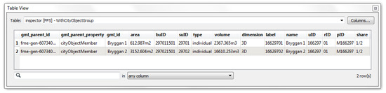
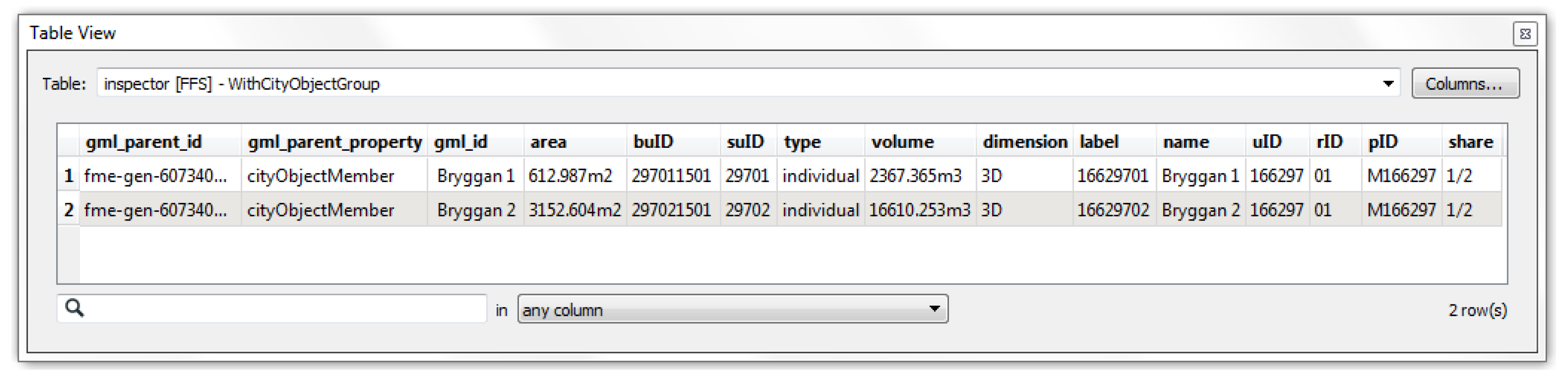
As for integrating attributes between CityGML 3.0 and LADM, the main step is to find common keys from the corresponding table. According to the UML diagram (Figure 17) and the feature types in CityGML 3.0, both CityObjctGroup and BuildingUnit can be integrated with LADM in this study. The gml_id (derived from CityObjctGroup in CityGML) and the name (from LADM) can be used as the common keys for integration (Figure 19). Note that the prefix grp from CityObjctGroup (Figure 18) is removed to enable a join with name from LADM (Figure 19).
Figure 19.
Integration of CityGML 3.0 with LADM based on CityObjectGroup.
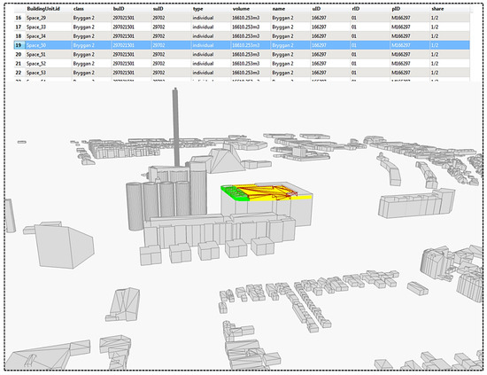
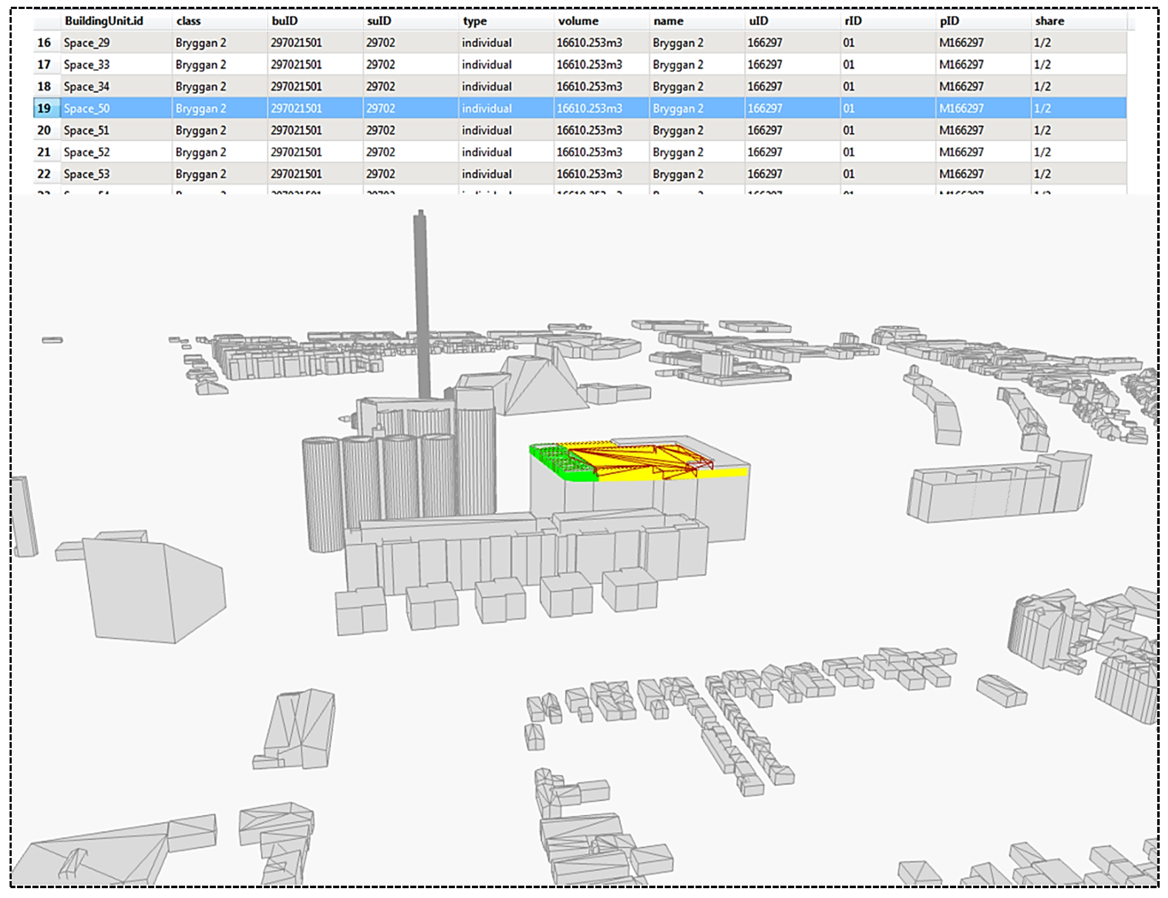
To represent a single logical space in the CityGML 3.0 file the class BuildingUnit is used and, in addition to attributes, geometries are defined in BuildingUnit. As shown in Figure 20, cadastral information can be visualized in a 3D city model when the corresponding building part is selected. Since the legal spaces (BuildingUnit) are subdivided into units smaller than the cadastral unit, the same cadastral information has to be repeated multiple times for connecting it with building units. In terms of BuildingUnit, the attribute class (from CityGML) and the attribute name (from LADM) are taken as keys for the integration.
Figure 20.
A simplified 3D cadastral index map based on integration of CityGML 3.0 and LADM DB with neighboring buildings. Bryggan 1 is in green color and Bryggan 2 in yellow. This should be compared with the current 2D cadastral index map in Figure 7.
5. Discussion
The proposed general framework and the formulated requirements were evaluated by implementing the case study for the IFC model of the building Multihuset and associated 3D cadastre. The results were generally satisfying with regards to the aspects discussed below. The discussion is solely based on the authors’ experience and knowledge (which is broad since the authors come both from the fields of cadastre and geodata/BIM), no external assessment has been performed.
(1) Organizational and legal perspectives
The cadastral surveying units should work on introducing 3D Public Law Regulations (PLR), establishing legal instruments to subdivide, and consolidating and managing 3D real property where needed. However, these instruments are often already in place, which leaves for example organizational matters to be developed and coordinated. Cadastral survey procedures should be developed when it comes to the coordination and collaboration between involved parties, which all bring their own data and documentation to the integration and visualization of the 3D cadastre. A major question is which party that should take responsibility to redefine real property in 3D space using unambiguous 3D terminology, in particular who should store and update the model and the related data. In the transition from current 2D real property to 3D, the two-dimensional data has to be converted to be used in a 3D environment and the information is often a result of older and more recent analogue and digital material, which then has to be inserted into a 3D cadastre model.
Obviously, it is difficult to completely represent real property only by 3D cadastral models. Through the case study, a proper method would be to maintain 2D cadastral dossiers, then generate a LADM profile in order to store and integrate cadastral data with physical models at the conceptual level and at the geometric level visualizing in 3D. In addition, not every storey has a detailed description of property boundaries in the cadastral dossiers, which makes it harder to identify property boundaries legally. For example, in some structure plans, the property boundaries are located along wall elements but without unambiguous descriptions stating if the boundary is along the inside/middle/outside of a wall. On the other hand, a boundary that is very precisely modelled will increase the risk of disagreeing with the building in relation to the plan. Previous research [24] shows that changes to current legislation and regulations might be necessary to enable the use of 3D digital data, and decisions on an organizational level might have to be made, e.g., when it comes to where the original data should be saved and who should have access to it. To obtain a uniform 3D cadastre the level of detail and information should be specified and agreed by all involved parties. Both quality and accuracy of the data is of importance in such decisions.
(2) Coordinate reference system and height system
The coordinates showed in the index map (Figure 4) are different from the construction plans (Figure 8). The reason is that the index map is surveyed and recorded in the coordinate system by geodetic methods while the construction plans were usually created via CAD in the engineering system by AEC companies, which makes the relative difference with a couple of centimeters because of the transformation.
(3) Data standards
For visualizing basic property units, IFC models should first be simplified. The edited IFC models are much easier to be accomplished by AEC companies, rather than the cadastral units. In order to identify property boundaries, a lower level of detail is sufficient, for example LOD 1 or LOD 2. Moreover, if the building parts share property rights, it is necessary to create a specific and complete UML model to integrate with physical models. This part should be done by cadastral units considering both conceptual and geometric aspects in LADM.
The results show that the efficiency for combining CityGML 3.0 with LADM is good. The new class AbstractLogicalSpace reduces the complexity of integrating procedures and increases the interoperability between the two standards; for that reason it is not required to create an ADE as it is for CityGML 2.0 (cf. [10]).
(4) Geometry
In the case study, the upper-left corner of Multihuset (except for the ground floor) is outside the property boundaries after construction (see Figure 13), which results in measured areas/volumes that are larger than calculated areas/volumes. On the other hand, the space boundaries drawn in the construction plans by cadastral units may clip wall or other elements without considering the construction structure. That will also cause ambiguous problems of the property management. Therefore, it is essential to amend cadastral survey procedures and update data recording.
(5) Users and user requirements
According to Table 1, various users and their specific needs should be considered and satisfied. However, the requirements and the general framework have only been tested on one floor and satisfied part requirements. More models will be tested in future research.
6. Conclusions
In this study, we propose a general framework for integrating cadastral information with BIM on the building level and with CityGML on the city level. Basic requirements for generating a 3D cadastral model are presented from six perspectives: organizational, legal, coordinate reference system and height system, data standards, geometry, and users. A case study, Multihuset, was used to implement and evaluate the use of 3D digital models to represent cadastral boundaries and visualize the 3D property units. Both an IFC model and a CityGML model were connected to LADM to generate an integrated 3D cadastral model at the conceptual level and on the database level. The main contributions of this study are the formulation of the requirements from legal and technical perspectives and the general framework for generating BIM and GIS-based 3D cadastral models in practice to support these requirements. The cadastral surveying units, AEC companies, and city-surveying units should work together on this, sharing information in the property formation and management process in a transition from the existing paper or PDF-format-based system to a general framework for the integration of cadastral information with BIM and GIS in the future. It is recommended that the cadastral units will continue developing processes and recommendations during this transition period to a new 3D based cadastral system, but all involved organizations will have to work more closely together in order to implement the proposed model. Our case study was conducted in Sweden, but nevertheless can be adapted for other similar countries.
Our research suggests that different organizations should share and exchange cadastral information during the whole life cycle in order to represent complex cadastral boundaries and generate comprehensive 3D cadastre. Compared with previous research [5,12,31,52], the results illustrate that the indirect method is possible to link BIM models (As-built BIM), city models (CityGML 3.0), and cadastral models after the construction phase in practice, which will enable a proper information exchange among different units and improve the interoperability. Nevertheless, we recommend establishing an information sharing mechanism that makes it easy and close to communicate among various units. On the other hand, data formats should be unified for further analysis, store, transfer, management, and update.
However, there are still some limitations in our study. The cadastral dossiers introduce the heights in a rough way, not detailed. Some plans have no description of property boundaries. There is one building corner that is beyond the property boundaries after construction, meaning that real measured and recorded areas and volumes are larger than those calculated in the model. However, in the design phase and building permit phase, the whole building is inside the property boundaries. According to the general framework, different organizations own and develop their own datasets. To generate 3D cadastral models, sharing and integrating information and models are necessary. However, in the practical project, it is disputed who should take responsibilities to generate 3D cadastral models.
Further research will focus on testing more models to fulfil the requirements and the general framework in practice. Another future work is to develop a collaborative workflow among different actors by using real-world case study through the life-cycle project.
Author Contributions
Conceptualization, Jing Sun and Lars Harrie; methodology, Jing Sun and Lars Harrie; software, Jing Sun, Siying Mi and Perola Olsson; formal analysis, Jing Sun and Jenny Paulsson; investigation, Jing Sun and Jenny Paulsson; data curation, Jing Sun and Perola Olsson; writing—original draft preparation, Jing Sun, Siying Mi, Jenny Paulsson, and Perola Olsson; writing—review and editing, Lars Harrie, Jing Sun, Jenny Paulsson and Perola Olsson; visualization, Jing Sun, Siying Mi and Perola Olsson; supervision, Lars Harrie and Jenny Paulsson; project administration, Lars Harrie; funding acquisition, Jing Sun and Lars Harrie.
Funding
This research was funded by the research platform Smart Built Environment, grant number 2016-01981 (financed by Formas, Vinnova and Swedish Energy Agency); and Lund University.
Acknowledgments
Thanks to Malmö municipality and NCC Company for providing cadastral dossiers, BIM data, and CityGML data for the study objects. Thanks to Safe Software for providing academic licenses of FME. Finally, we thank Helen Eriksson and Väino Tarandi for discussions about this study.
Conflicts of Interest
The authors declare no conflict of interest. The funders had no role in the design of the study; in the collection, analyses, or interpretation of data; in the writing of the manuscript, or in the decision to publish the results.
References
- International Federation of Surveyors (FIG). Best Practices 3D Cadastres—Extended Version; International Federation of Surveyors: Copenhagen, Denmark, 2018. [Google Scholar]
- Shojaei, D.; Kalantari, M.; Bishop, I.D.; Rajabifard, A.; Aien, A. Visualization requirements for 3D cadastral systems. Comput. Environ. Urban Syst. 2013, 41, 39–54. [Google Scholar] [CrossRef] [Scilit]
- Aien, A.; Rajabifard, A.; Kalantari, M.; Shojaei, D. Integrating legal and physical dimensions of urban environments. ISPRS Int. J. Geo Inf. 2015, 4, 1442–1479. [Google Scholar] [CrossRef] [Scilit]
- Drobež, P.; Fras, M.K.; Ferlan, M.; Lisec, A. Transition from 2D to 3D real property cadastre: The case of the Slovenian cadastre. Comput. Environ. Urban Syst. 2017, 62, 125–135. [Google Scholar] [CrossRef] [Scilit]
- Atazadeh, B.; Kalantari, M.; Rajabifard, A.; Ho, S.; Ngo, T. Building information modelling for high-rise land administration. Trans. GIS 2017, 21, 91–113. [Google Scholar] [CrossRef] [Scilit]
- Li, L.; Wu, J.; Zhu, H.; Duan, X.; Luo, F. 3D modeling of the ownership structure of condominium units. Comput. Environ. Urban Syst. 2016, 59, 50–63. [Google Scholar] [CrossRef] [Scilit]
- Andrée, M.; Paasch, J.M.; Paulsson, J.; Seipel, S. BIM and 3D property visualisation. In Proceedings of the FIG Congress, Istanbul, Turkey, 6–11 May 2018. [Google Scholar]
- Eastman, C.; Teicholz, P.; Sacks, R.; Liston, K. BIM Handbook: A Guide to Building Information Modelling for Owners, Managers, Designers, Engineers and Contractors, 2nd ed.; John Wiley and Sons, Inc.: Hoboken, NJ, USA, 2011. [Google Scholar]
- International Organization for Standardization (ISO). Industry Foundation Classes (IFC) for Data Sharing in the Construction and Facility Management Industries—Part 1: Data Schema; ISO 16739-1; ISO: Geneva, Switzerland, 2018. [Google Scholar]
- Kutzner, T.; Kolbe, T.H. CityGML 3.0: Sneak Preview. In Proceedings of the PFGK18—Photogrammetrie Fernerkundung Geoinformatik Kartographie, 37. Jahrestagung in München, München, Germany, 23 February 2018. [Google Scholar]
- International Organization for Standardization (ISO). Geographic Information—Land Administration Domain Model (LADM); ISO 19152; ISO: Geneva, Switzerland, 2012. [Google Scholar]
- Góźdź, K.; Pachelski, W.; van Oosterom, P.; Coors, V. The possibilities of using CityGML for 3D representation of buildings in the cadastre. In Proceedings of the 4th International Workshop on 3D Cadastres, Dubai, UAE, 9–11 November 2014. [Google Scholar]
- Rönsdorff, C.; Wilson, D.; Stoter, J. Integration of land administration domain model with CityGML for 3D cadastre. In Proceedings of the 4th International Workshop on 3D Cadastres, Dubai, UAE, 9–11 November 2014. [Google Scholar]
- Aien, A.; Rajabifard, A.; Kalantari, M.; Williamson, I. Review and assessment of current cadastral data models for 3D cadastral applications. In Lecture Notes in Geoinformation and Cartography; Springer: Cham, Switzerland, 2017; pp. 423–442. [Google Scholar]
- El-Mekawy, M.; Paasch, J.; Paulsson, J. The integration of 3D cadastre, 3D property formation and BIM in Sweden. In Proceedings of the 4th International FIG 3D Cadastre Workshop, Dubai, UAE, 9–11 November 2014. [Google Scholar]
- Van Oosterom, P. Research and development in 3D cadastres. Comput. Environ. Urban Syst. 2013, 40, 1–6. [Google Scholar] [CrossRef] [Scilit]
- Van Oosterom, P.; Lemmen, C.; Thompson, R.; Janečka, K.; Zlatanova, S.; Kalantari, M. 3D cadastral information modelling. In Best Practices 3D Cadastres—Extended Version; FIG Publication: Copenhagen, Denmark, 2018. [Google Scholar]
- Stoter, J.; Ploeger, H.; Roes, R.; van der Riet, E.; Biljecki, F.; Ledoux, H. First 3D cadastral registration of multi-level ownerships rights in The Netherlands. In Proceedings of the 5th International FIG 3D Cadastre Workshop, Aten, Grekland, 18–20 October 2016. [Google Scholar]
- Shojaei, D.; Olfat, H.; Rajabifard, A.; Kalantari, M.; Briffa, M. Moving towards a fully operational 3D digital cadastre: Victoria, Australia. In Proceedings of the 6th International FIG 3D Cadastre Workshop, Delft, The Netherlands, 2–4 October 2018. [Google Scholar]
- Kalantari, M.; Kalogianni, E. Towards LADM Victoria country profile—Modelling the spatial information. In Proceedings of the 6th International FIG 3D Cadastre Workshop, Delft, The Netherlands, 2–4 October 2018. [Google Scholar]
- Guo, R.; Luo, F.; Zhao, Z.; He, B.; Li, L.; Luo, P.; Ying, S. The applications and practices of 3D cadastre in Shenzhen. In Proceedings of the 4th International Workshop on 3D Cadastres, Dubai, UAE, 9–11 November 2014. [Google Scholar]
- Lantmäteriet. Cadastral Procedures in Sweden; Lantmäteriet: Gavle, Sweden, 2011. [Google Scholar]
- El-Mekawy, M.S.A.; Paasch, J.M.; Paulsson, J. Integration of legal aspects in 3D cadastral systems. In 3D Printing: Breakthroughs in Research and Practice; IGI Global: Hershey, PA, USA, 2016; pp. 119–144. [Google Scholar]
- Larsson, K.; Paasch, J.; Paulsson, J. Conversion of 2D analogue cadastral boundary plans into 3D digital information—Problems and challenges illustrated by a Swedish case. In Proceedings of the 6th International FIG 3D Cadastre Workshop, Delft, The Netherlands, 2–4 October 2018. [Google Scholar]
- Lemmen, C.; van Oosterom, P.; Bennett, R. The land administration domain model. Land Use Policy 2015, 49, 535–545. [Google Scholar] [CrossRef] [Scilit]
- Borrmann, A.; Beetz, J.; Koch, C.; Liebich, T.; Muhic, S. Industry foundation classes: A standardized data model for the vendor-neutral exchange of digital building models. In Building Information Modeling: Technology Foundations and Industry Practice; Borrmann, A., König, M., Koch, C., Beetz, J., Eds.; Springer International Publishing: Cham, Switzerland, 2018; pp. 81–126. [Google Scholar]
- International Organization for Standardization (ISO). Organization and Digitization of Information about Buildings and Civil Engineering Works, including Building Information Modelling (BIM)—Information Management Using Building Information Modelling—Part 1: Concepts and Principles; ISO 19650-1; ISO: Geneva, Switzerland, 2018. [Google Scholar]
- International Organization for Standardization (ISO). Organization and Digitization of Information about Buildings and Civil Engineering Works, including Building Information Modelling (BIM)—Information Management Using Building Information Modelling—Part 2: Delivery Phase of the Assets; ISO 19650-2; ISO: Geneva, Switzerland, 2018. [Google Scholar]
- Steinmann, R. IFC certification of BIM software. In Building Information Modeling: Technology Foundations and Industry Practice; Borrmann, A., König, M., Koch, C., Beetz, J., Eds.; Springer International Publishing: Cham, Switzerland, 2018; pp. 139–153. [Google Scholar]
- Liebich, T. IFC 2x Edition 2 Model Implementation Guide; International Alliance for Interoperability: Kettering, UK, 2004. [Google Scholar]
- Atazadeh, B.; Kalantari, M.; Rajabifard, A.; Ho, S. Modelling building ownership boundaries within BIM environment: A case study in Victoria, Australia. Comput. Environ. Urban Syst. 2017, 61, 24–38. [Google Scholar] [CrossRef] [Scilit]
- Atazadeh, B.; Rajabifard, A.; Zhang, Y.; Barzegar, M. Querying 3D cadastral information from BIM models. ISPRS Int. J. Geo Inf. 2019, 8, 329. [Google Scholar] [CrossRef] [Scilit]
- Oldfield, J.; van Oosterom, P.; Beetz, J.; Krijnen, T.F. Working with open BIM standards to source legal spaces for a 3D cadastre. ISPRS Int. J. Geo Inf. 2017, 6, 351. [Google Scholar] [CrossRef] [Scilit]
- Gröger, G.; Plümer, L. CityGML—Interoperable semantic 3D city models. ISPRS J. Photogramm. Remote Sens. 2012, 71, 12–33. [Google Scholar] [CrossRef] [Scilit]
- Open Geospatial Consortium (OGC). OGC City Geography Markup Language (CityGML) Encoding Standard; OGC: Wayland, MA, USA, 2012. [Google Scholar]
- Sun, J.; Olsson, P.-O.; Eriksson, H.; Harrie, L. Evaluating the geometric aspects of integrating BIM data into city models. J. Spat. Sci. 2019. [Google Scholar] [CrossRef] [Scilit]
- Biljecki, F.; Kumar, K.; Nagel, C. CityGML application domain extension (ADE): Overview of developments. Open Geospat. DataSoftw. Stand. 2018, 3, 13. [Google Scholar] [CrossRef] [Scilit]
- Van den Brink, L.; Stoter, J.; Zlatanova, S. UML-Based approach to developing a CityGML application domain extension. Trans. GIS 2013, 17, 920–942. [Google Scholar] [CrossRef] [Scilit]
- CityGML 3.0 Conceptual Model. Available online: https://github.com/opengeospatial/CityGML-3.0CM/tree/master/Conceptual%20Model (accessed on 13 June 2019).
- Ohori, K.A.; Biljecki, F.; Kumar, K.; Ledoux, H.; Stoter, J. Modeling cities and landscapes in 3D with CityGML. In Building Information Modeling: Technology Foundations and Industry Practice; Borrmann, A., König, M., Koch, C., Beetz, J., Eds.; Springer International Publishing: Cham, Switzerland, 2018; pp. 199–215. [Google Scholar]
- Sun, J.; Harrie, L.; Jensen, A.; Eriksson, H.; Tarandi, V.; Uggla, G. Description of Geodata Quality with Focus on Integration of BIM-Data and Geodata. 2018 Smart Built Environment. Available online: https://www.smartbuilt.se/library/3878/description-of-geodata-quality-2018-04-16-002.pdf (accessed on 13 June 2019).
- Ohori, K.A.; Biljecki, F.; Diakité, A.; Krijnen, T.; Ledoux, H.; Stoter, J. Towards an integration of GIS and BIM data: What are the geometric and topological issues? In Proceedings of the 12th 3D Geoinfo Conference, ISPRS Annals of the Photogrammetry, Remote Sensing and Spatial Information Sciences, Melbourne, Australia, 26–27 October 2017. [Google Scholar]
- Sun, J.; Eriksson, H.; Harrie, L.; Jensen, A. Sharing building information from planning to maintenance phases. In Proceedings of the 21st AGILE Conference on Geographic Information Science, Lund, Sweden, 12–15 June 2018. [Google Scholar]
- Olsson, P.-O.; Axelsson, J.; Hooper, M.; Harrie, L. Automation of building permission by integration of BIM and geospatial data. ISPRS Int. J. Geo Inf. 2018, 7, 307. [Google Scholar] [CrossRef] [Scilit]
- Donkers, S.; Ledoux, H.; Zhao, J.Q.; Stoter, J. Automatic conversion of IFC datasets to geometrically and semantically correct CityGML LOD3 buildings. Trans. GIS 2016, 20, 547–569. [Google Scholar] [CrossRef] [Scilit]
- Stouffs, R.; Tauscher, H.; Biljecki, F. Achieving complete and near-lossless conversion from IFC to CityGML. ISPRS Int. J. Geo Inf. 2018, 7, 355. [Google Scholar] [CrossRef] [Scilit]
- Floros, G.; Pispidikis, I.; Dimopoulou, E. Investigating integration capabilities between IFC and CityGML LOD3 for 3D city modelling. In Proceedings of the 12th 3D Geoinfo Conference 2017, Melbourne, Australia, 26–27 October 2017. [Google Scholar]
- Olsson, P.-O. Conversion of an IFC-model to a LOD2-3 3D-GIS building model. In Proceedings of the AGILE Conference, Lund, Sweden, 12–15 June 2018. [Google Scholar]
- Kitsakis, D.; Kalantari, M.; Rajabifard, A.; Atazadeh, B.; Dimopoulou, E. Exploring the 3 rd dimension within public law restrictions: A case study of Victoria, Australia. Land Use Policy 2019, 85, 195–206. [Google Scholar] [CrossRef] [Scilit]
- Aien, A.; Kalantari, M.; Rajabifard, A.; Williamson, I.; Wallace, J. Towards integration of 3D legal and physical objects in cadastral data models. Land Use Policy 2013, 35, 140–154. [Google Scholar] [CrossRef] [Scilit]
- Pouliot, J.; Ellul, C.; Hubert, F.; Wang, C.; Rajabifard, A.; Kalantari, M.; Shojaei, D.; Atazadeh, B.; Oosterom, P.; de Vries, M.; et al. Visualization and new opportunities. In Best Practices 3D Cadastres; FIG: Copenhagen, Denmark, 2018. [Google Scholar]
- Çağdaş, V. An application domain extension to CityGML for immovable property taxation: A Turkish case study. Int. J. Appl. Earth Obs. Geoinf. 2013, 21, 545–555. [Google Scholar] [CrossRef] [Scilit]



© 2019 by the authors. Licensee MDPI, Basel, Switzerland. This article is an open access article distributed under the terms and conditions of the Creative Commons Attribution (CC BY) license (http://creativecommons.org/licenses/by/4.0/).