Use of Unmanned Aerial Vehicles (UAVs) for Updating Farmland Cadastral Data in Areas Subject to Landslides


Abstract
1. Introduction
2. Materials and Methods
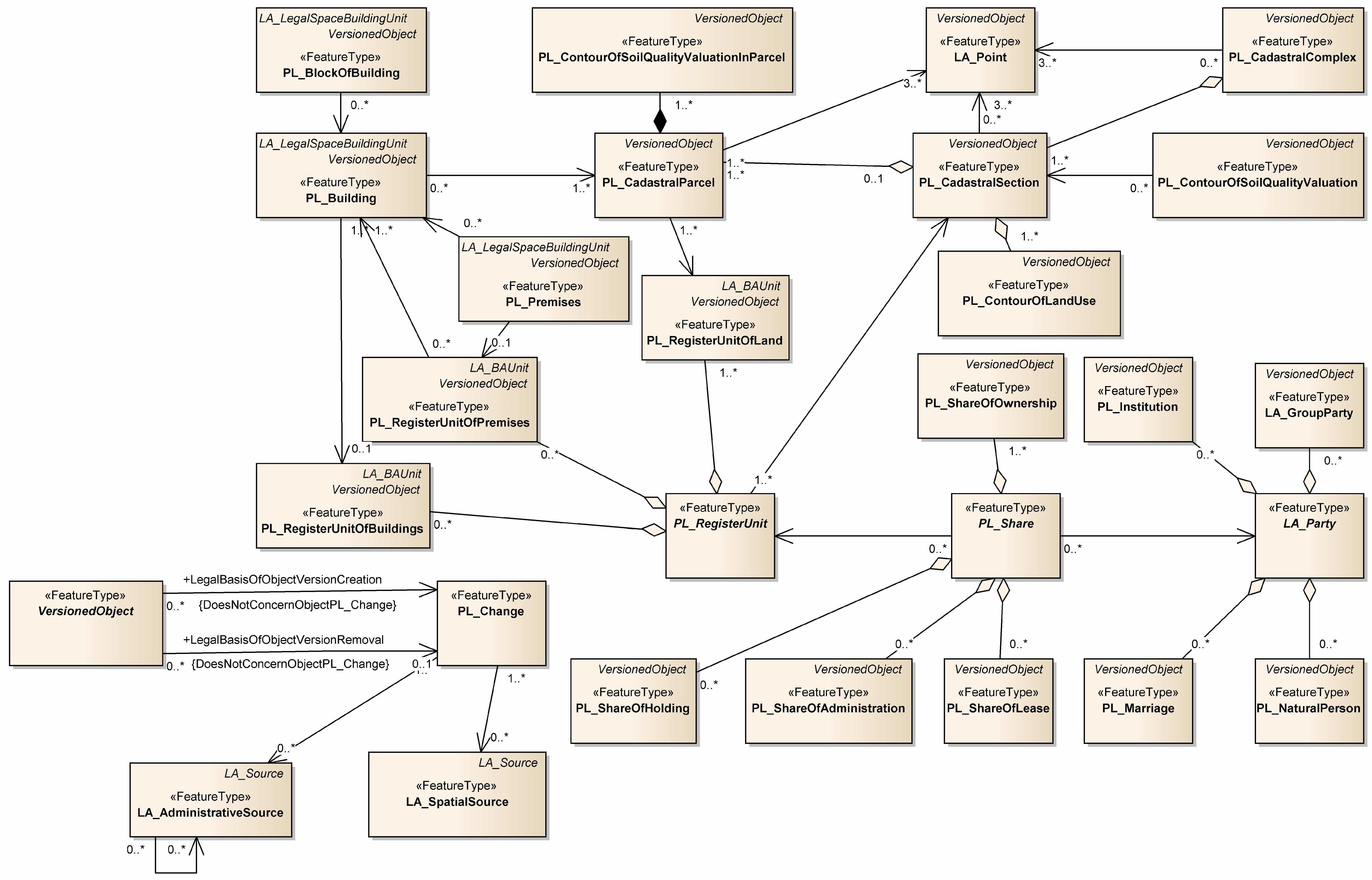
2.1. Cadastral Data Requirements
2.2. Accuracy Requirements
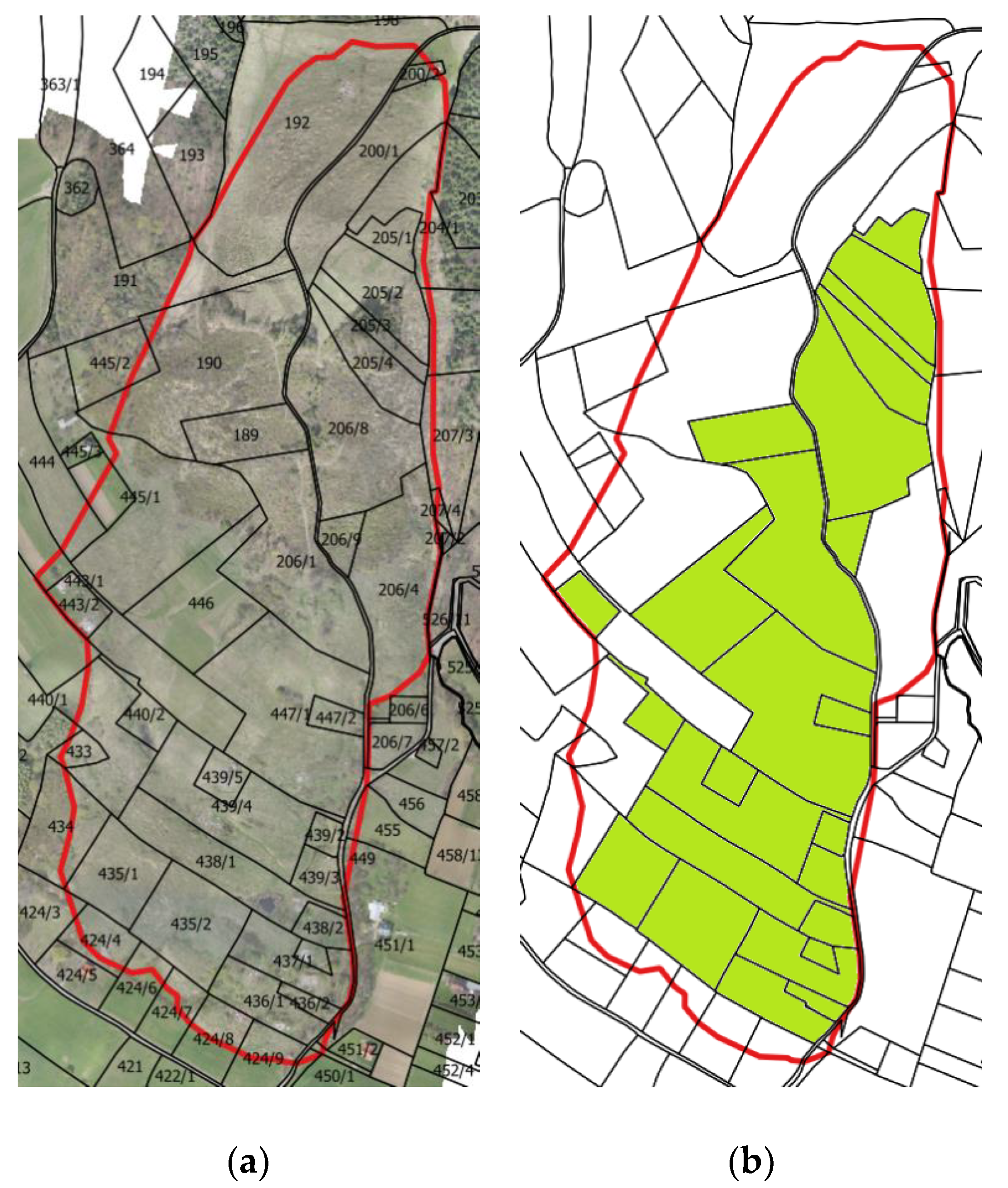
2.3. Updating the Cadastre with Respect to Landslide Sites
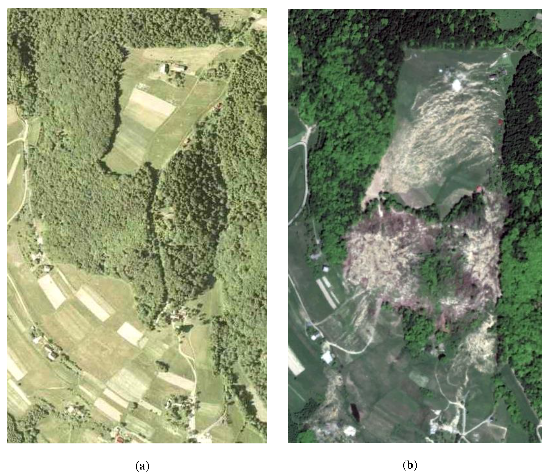
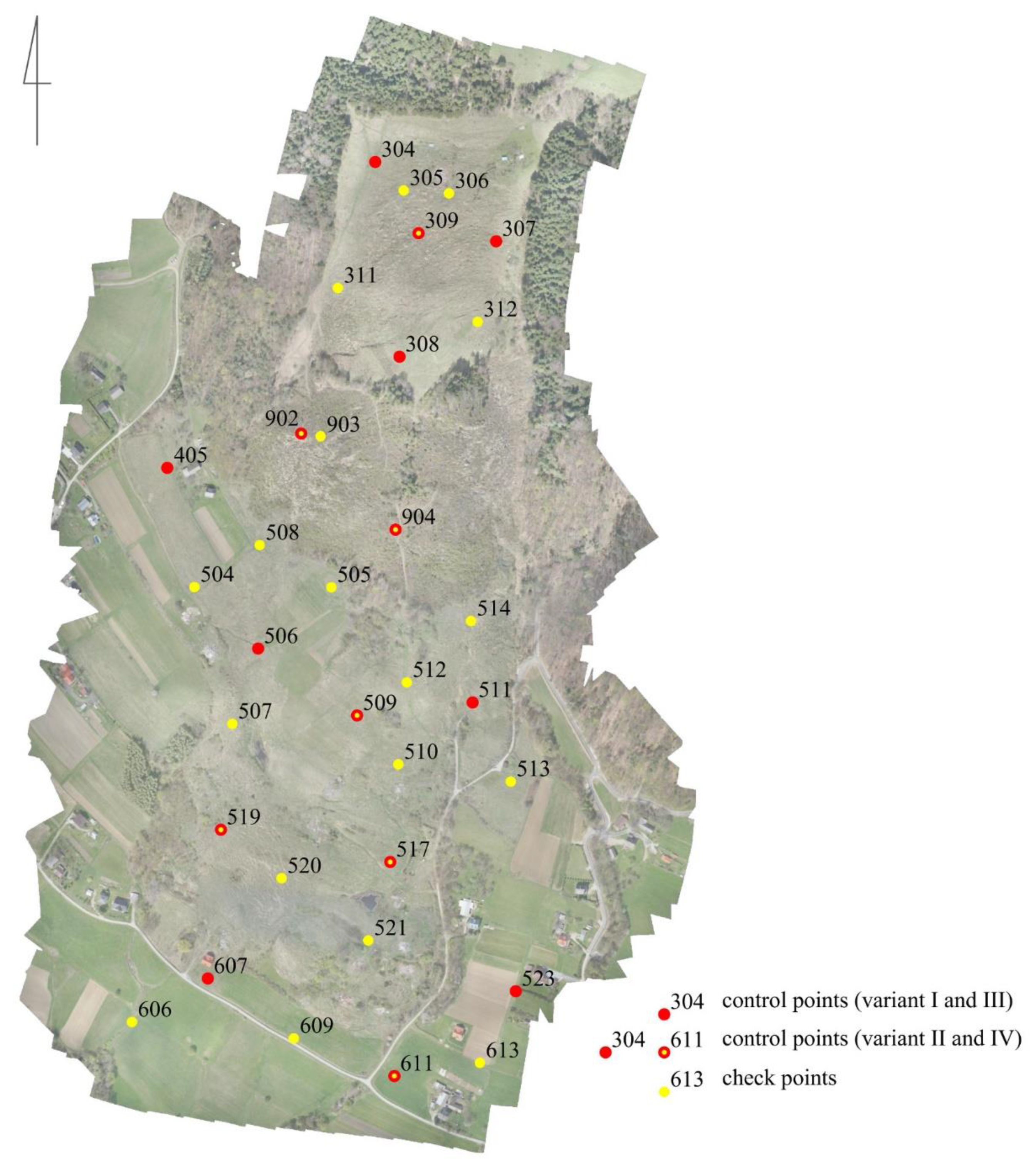
2.4. Survey Site
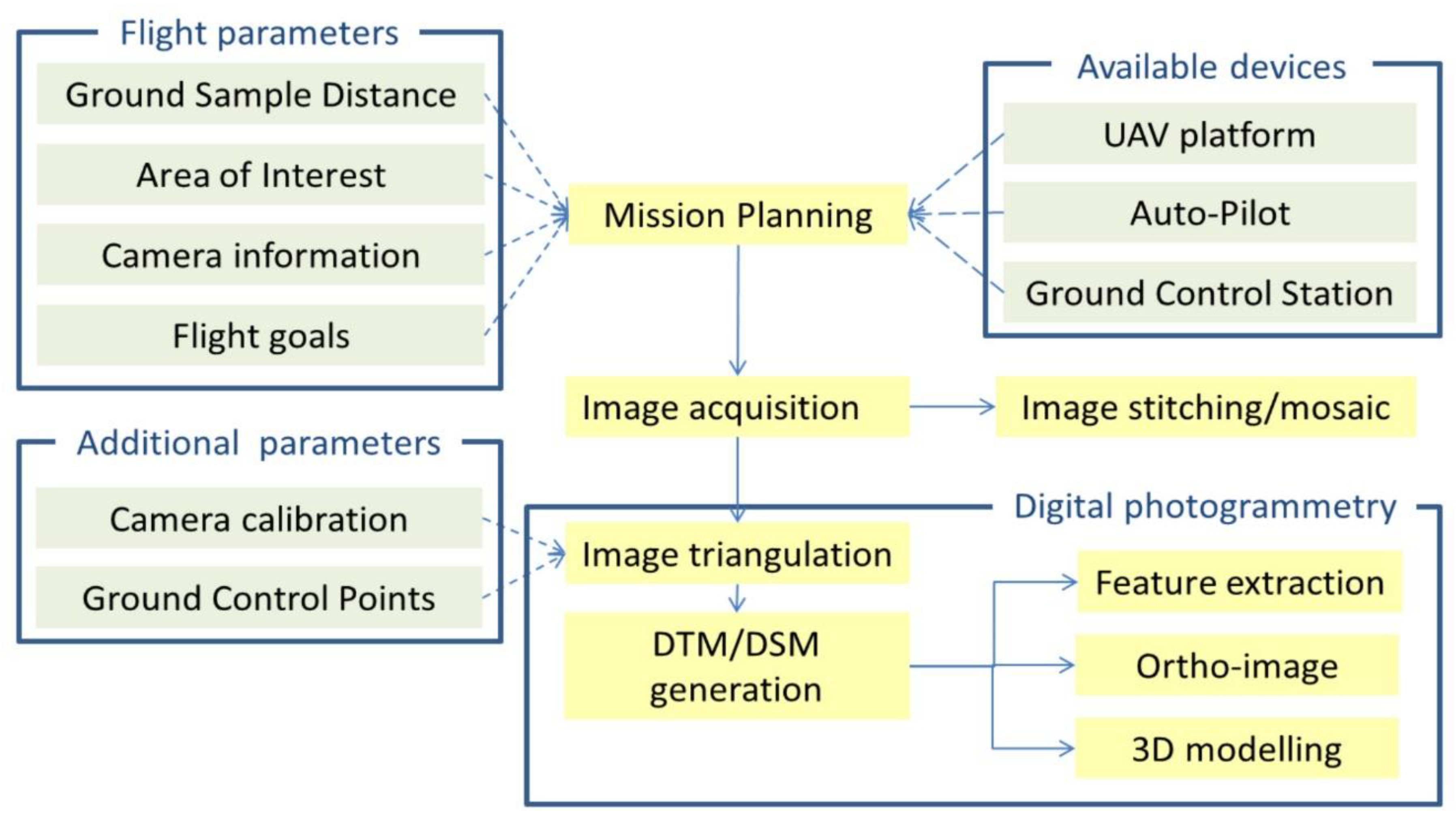
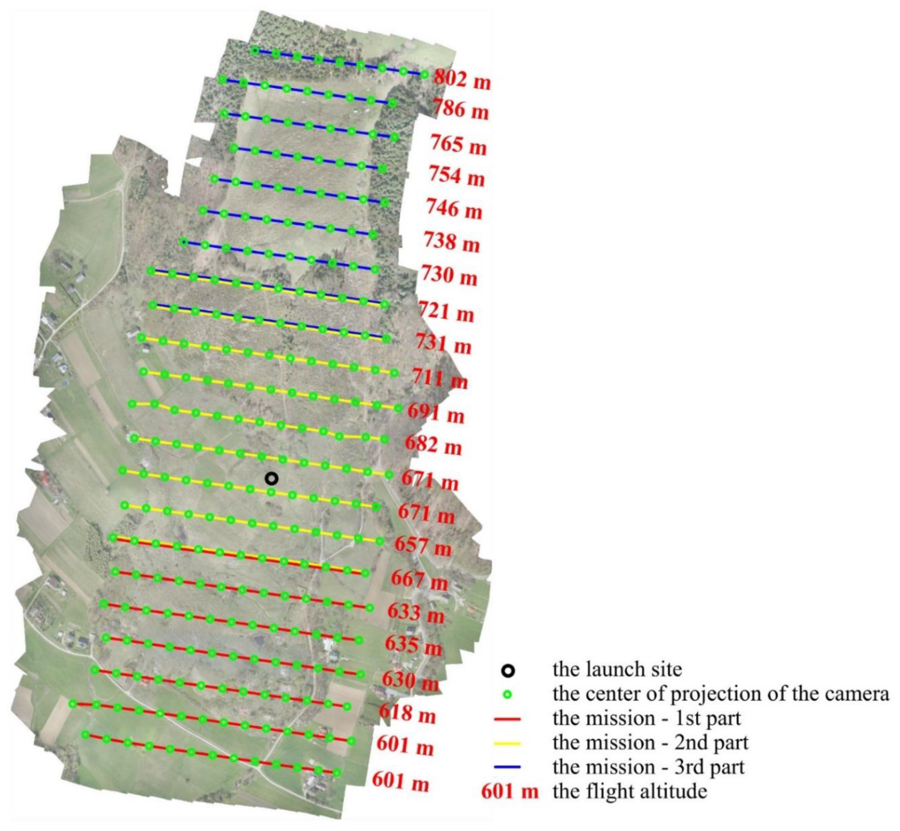
2.5. Study Methods
3. Results and Discussion
- mxy = 30 mm and mh = 50 mm for RTK GNSS;
- mxy = 5 mm and mh = 15 mm for static GNSS.
4. Conclusions
Author Contributions
Funding
Acknowledgments
Conflicts of Interest
References
- Puniach, E.; Kwartnik-Pruc, A.; Ćwiąkała, P. Use of unmanned aerial vehicles in Poland. In Proceedings of the GIS ODYSSEY 2016, Geographic Information Systems Conference and Exhibition, Perugia, Italy, 5–9 September 2016; pp. 207–217. [Google Scholar]
- Stöcker, C.; Bennett, R.; Nex, F.; Gerke, M.; Zevenbergen, J. Review of the Current State of UAV Regulations. Remote Sens. 2017, 9, 459. [Google Scholar] [CrossRef]
- Watts, A.C.; Ambrosia, V.G.; Hinkley, E.A. Unmanned Aircraft Systems in Remote Sensing and Scientific Research: Classification and Considerations of Use. Remote Sens. 2012, 4, 1671–1692. [Google Scholar] [CrossRef]
- Cramer, M.; Bovet, S.; Gültlinger, M.; Honkavaara, E.; McGill, A.; Rijsdijk, M.; Tabor, M.; Tournadre, V. On the use of RPAS in national mapping—The EuroSDR point of view. Int. Arch. Photogramm. Remote Sens. Spat. Inf. Sci. 2013, XL-1/W2, 93–99. [Google Scholar] [CrossRef]
- Haarbrink, R. UAS for geo-information: Current status and perspectives. Int. Arch. Photogramm. Remote Sens. Spat. Inf. Sci. 2011, XXXVIII-1/C22, 207–212. [Google Scholar] [CrossRef]
- Guerra-Hernández, J.; González-Ferreiro, E.; Monleón, V.J.; Faias, S.P.; Tomé, M.; Díaz-Varela, R.A. Use of Multi-Temporal UAV-Derived Imagery for Estimating Individual Tree Growth in Pinus pinea Stands. Forests 2017, 8, 300. [Google Scholar] [CrossRef]
- Du, M.; Noguchi, N. Monitoring of Wheat Growth Status and Mapping of Wheat Yield’s within-Field Spatial Variations Using Color Images Acquired from UAV-camera System. Remote Sens. 2017, 9, 289. [Google Scholar] [CrossRef]
- Wachholz de Souza, C.H.; Lamparelli, R.A.C.; Rocha, J.V.; Magalhães, P.S.G. Mapping skips in sugarcane fields using object-based analysis of unmanned aerial vehicle (UAV) images. Comput. Electron. Agric. 2017, 143, 49–56. [Google Scholar] [CrossRef]
- Schirrmann, M.; Giebel, A.; Gleiniger, F.; Pflanz, M.; Lentschke, J.; Dammer, K.-H. Monitoring Agronomic Parameters of Winter Wheat Crops with Low-Cost UAV Imagery. Remote Sens. 2016, 8, 706. [Google Scholar] [CrossRef]
- Husson, E.; Ecke, F.; Reese, H. Comparison of Manual Mapping and Automated Object-Based Image Analysis of Non-Submerged Aquatic Vegetation from Very-High-Resolution UAS Images. Remote Sens. 2016, 8, 724. [Google Scholar] [CrossRef]
- Park, S.; Ryu, D.; Fuentes, S.; Chung, H.; Hernández-Montes, E.; O’Connell, M. Adaptive Estimation of Crop Water Stress in Nectarine and Peach Orchards Using High-Resolution Imagery from an Unmanned Aerial Vehicle (UAV). Remote Sens. 2017, 9, 828. [Google Scholar] [CrossRef]
- Zhang, Y.; Yuan, X.; Fang, Y.; Chen, S. UAV Low Altitude Photogrammetry for Power Line Inspection. ISPRS Int. J. Geo-Inf. 2017, 6, 14. [Google Scholar] [CrossRef]
- Vacca, G.; Dessì, A.; Sacco, A. The Use of Nadir and Oblique UAV Images for Building Knowledge. ISPRS Int. J. Geo-Inf. 2017, 6, 393. [Google Scholar] [CrossRef]
- Emran, B.J.; Tannant, D.D.; Najjaran, H. Low-Altitude Aerial Methane Concentration Mapping. Remote Sens. 2017, 9, 823. [Google Scholar] [CrossRef]
- Xue, X.; Lan, Y.; Sun, Z.; Chang, Ch.; Hoffmann, W.C. Develop an unmanned aerial vehicle based automatic aerial spraying system. Comput. Electron. Agric. 2016, 128, 58–66. [Google Scholar] [CrossRef]
- Niethammer, U.; James, M.R.; Rothmunda, S.; Travelletti, J.; Joswiga, M. UAV-based remote sensing of the Super-Sauze landslide: Evaluation and results. Eng. Geol. 2012, 128, 2–11. [Google Scholar] [CrossRef]
- Turner, D.; Lucieer, A.; de Jong, S.M. Time Series Analysis of Landslide Dynamics Using an Unmanned Aerial Vehicle (UAV). Remote Sens. 2015, 7, 1736–1757. [Google Scholar] [CrossRef]
- Al-Rawabdeh, A.; He, F.; Moussa, A.; El-Sheimy, N.; Habib, A. Using an Unmanned Aerial Vehicle-Based Digital Imaging System to Derive a 3D Point Cloud for Landslide Scarp Recognition. Remote Sens. 2016, 8, 95. [Google Scholar] [CrossRef]
- Fernández, T.; Pérez, J.L.; Cardenal, J.; Gómez, J.M.; Colomo, C.; Delgado, J. Analysis of Landslide Evolution Affecting Olive Groves Using UAV and Photogrammetric Techniques. Remote Sens. 2016, 8, 837. [Google Scholar] [CrossRef]
- Rothmund, S.; Vouillamoz, N.; Joswig, M. Mapping slow-moving alpine landslides by UAV—Opportunities and limitations. Lead Edge 2017, 36, 571–579. [Google Scholar] [CrossRef]
- Casagli, N.; Frodella, W.; Morelli, S.; Tofani, V.; Ciampalini, A.; Intrieri, E.; Raspini, F.; Rossi, G.; Tanteri, L.; Lu, P. Spaceborne, UAV and ground-based remote sensing techniques for landslide mapping, monitoring and early warning. Geoenviron. Disasters 2017, 4, 9. [Google Scholar] [CrossRef]
- Manyoky, M.; Theiler, P.; Steudler, D.; Eisenbeiss, H. Unmanned aerial vehicle in cadastral applications. Int. Arch. Photogramm. Remote Sens. Spat. Inf. Sci. 2011, XXXVIII-1/C22, 57–62. [Google Scholar] [CrossRef]
- Jazayeri, I.; Rajabifard, A.; Kalantari, M. A geometric and semantic evaluation of 3D data sourcing methods for land and property information. Land Use Policy 2014, 36, 219–230. [Google Scholar] [CrossRef]
- Mesas-Carrascosa, F.J.; Notario-García, M.D.; de Larriva, J.E.M.; de la Orden, M.S.; Porras, A.G.-F. Validation of measurements of land plot area using UAV imagery. Int. J. Appl. Earth Obs. Geoinf. 2014, 33, 270–279. [Google Scholar] [CrossRef]
- Stępień, G.; Sanecki, J.; Klewski, A.; Beczkowski, K. Wyznaczanie granic użytków rolnych z wykorzystaniem bezzałogowych systemów latających (Determination of agricultural land borders using unmanned aerial systems). Infrastruct. Ecol. Rural Areas 2014, III/2, 1011–1024. [Google Scholar] [CrossRef]
- Crommelinck, S.; Bennett, R.; Gerke, M.; Nex, F.; Yang, M.Y.; Vosselman, G. Review of Automatic Feature Extraction from High-Resolution Optical Sensor Data for UAV-Based Cadastral Mapping. Remote Sens. 2016, 8, 689. [Google Scholar] [CrossRef]
- Colomina, I.; Molina, P. Unmanned aerial systems for photogrammetry and remote sensing: A review. ISPRS J. Photogramm. Remote Sens. 2014, 92, 79–97. [Google Scholar] [CrossRef]
- Everaerts, J. The use of unmanned aerial vehicles (UAVs) for remote sensing and mapping. Proc. ISPRS 2008, 37, 1187–1192. [Google Scholar]
- Remondino, F.; Barazzetti, L.; Nex, F.; Scaioni, M.; Sarazzi, D. UAV photogrammetry for mapping and 3D modeling: Current status and future perspectives. Proc. ISPRS 2011, 38/C22, 25–31. [Google Scholar] [CrossRef]
- Hashim, N.M.; Omar, A.H.; Ramli, S.N.M.; Omar, K.M.; Din, N. Cadastral database positional accuracy improvement. Proc. ISPRS 2017, 42, 91–96. [Google Scholar] [CrossRef]
- Geodetic and Cartographic Law of 17 May 1989. Journal of Laws of 2016, Item 1629 (as Amended), Poland. Available online: http://prawo.sejm.gov.pl/isap.nsf/download.xsp/WDU20170002101/T/D20172101L.pdf (accessed on 9 February 2018).
- Bieda, A.; Bydłosz, J.; Parzych, P. Actualization of data concerning surface flowing waters, based on INSPIRE directive requirements. Geom. Environ. Eng. 2013, 7, 25–36. [Google Scholar] [CrossRef]
- Balawejder, M.; Adamczyk, T.; Cygan, M. The problem of adjusting polish spatial information resources to the standards of the inspire. In Proceedings of the GIS ODYSSEY 2016, Geographic Information Systems Conference and Exhibition, Perugia, Italy, 5–9 September 2016; pp. 14–24. [Google Scholar]
- Hycner, R. Ewidencja gruntów i budynków w Polsce jako kataster (Registration of land and buildings in Poland as a cadastre). Acta Sci. Acad. Ostroviensis 2006, 23, 19–43. (In Polish) [Google Scholar]
- Bydłosz, J. The application of the Land Administration Domain Model in building a country profile for the Polish cadastre. Land Use Policy 2015, 49, 598–605. [Google Scholar] [CrossRef]
- Stock, K.M. Accuracy Requirements for Rural Land Parcel Boundaries. J. Aust. Surv. 1998, 43, 165–171. [Google Scholar] [CrossRef]
- Nisbet, K.A. Procedures for the South Australian Legal Coordinated Cadastre. In Proceedings of the International Conference on Cadastral Reform, Melbourne, Australia, 29 June–1 July 1992; Hunter, G.J., Williamson, I.P., Eds.; Department of Surveying and Land Information, University of Melbourne: Melbourne, Australia, 1992. [Google Scholar]
- Rijsdijk, M.; van Hinsbergh, W.H.M.; Witteveen, W.; Buuren, G.H.M.; Schakelaar, G.A.; Poppinga, G.; Persie, M.V.; Ladige, R. Unmanned aerial systems in the process of juridical verification of cadastral border. Proc. ISPRS 2013, 61, 325–331. [Google Scholar] [CrossRef]
- Handleiding Technische Werkzaamheden (HTW) Kadaster; Kadaster: Apeldoorn, The Netherlands, 1994.
- Siriba, D. Positional Accuracy Assessment of a Cadastral Dataset based on the Knowledge of the Process Steps used. In Proceedings of the 12th AGILE International Conference on Geographic Information Science, Hannover, Germany, 2–5 June 2009. [Google Scholar]
- Das Eidgenössische Departement für Verteidigung, Bevölkerungsschutz und Sport, Technische Verordnung des VBS über die Amtliche Vermessung, 10. June 1994 (Stand 1. Juli 2008). pp. 2–16. Available online: https://www.admin.ch/opc/de/classified-compilation/19940126/ (accessed on 9 February 2018).
- Der Schweizerische Bundesrat, Verordnung über die Amtliche Vermessung, 18. November 1992 (Stand 1. July 2008). pp. 2–3. Available online: https://www.admin.ch/opc/de/classified-compilation/19920299/ (accessed on 9 February 2018).
- Hanus, P.; Pęska-Siwik, A.; Szewczyk, R. Spatial analysis of the accuracy of the cadastral parcel boundaries. Comput. Electron. Agric. 2018, 144, 9–15. [Google Scholar] [CrossRef]
- Regulation of the Minister of Regional Development and Construction of 29 March 2001 on the Register of Land and Buildings. Available online: http://prawo.sejm.gov.pl/isap.nsf/download.xsp/WDU20160001034/O/D20161034.pdf (accessed on 9 February 2018).
- Regulation of the Minister of Internal Affairs and Administration of 9 November 2011 on the Technical Standards for the Performance of Surveying Detailed Measurements, as Well as the Preparation and Transfer of These Measurement Results to the National Cartographic Information Center Database. Available online: http://prawo.sejm.gov.pl/isap.nsf/download.xsp/WDU20112631572/O/D20111572.pdf (accessed on 9 February 2018).
- Bieda, A.; Hanus, P.; Jasińska, E.; Preweda, E. Accuracy of Determination of Real Estate Area. International Conference Environmental Engineering. Available online: http://leidykla.vgtu.lt/conferences/ENVIRO_2014/Articles/5/191_Bieda.pdf (accessed on 9 February 2018).
- Akińcza, M.; Bieda, A.; Buśko, M.; Hannibal, H.; Hanus, P.; Hycner, R.; Krzyżek, R.; Kwartnik-Pruc, A.; Łuczyński, R.; Przewięźlikowska, A. Aktualne Problemy Katastru w Polsce (Present Cadastral Problems in Poland); Oficyna Wydawnicza Politechniki Warszawskiej: Warszawa, Poland, 2014. (In Polish) [Google Scholar]
- Environmental Protection Law of 27 April 2001. Journal of Laws of 2017, Item 519, Poland. Available online: http://prawo.sejm.gov.pl/isap.nsf/download.xsp/WDU20170000519/O/D20170519.pdf (accessed on 9 February 2018).
- Act of 11 August 2001 on Special Principles of the Reconstruction, Renovation and Demolition of Building Structures Destroyed or Damaged as a Result of the Action of the Element. Journal of Laws of 2016, Item 1067 (as Amended), Poland. Available online: http://prawo.sejm.gov.pl/isap.nsf/download.xsp/WDU20160001067/U/D20161067Lj.pdf (accessed on 9 February 2018).
- Bieda, A.; Hanus, P. Subdivision as a tool for regulating and approving legal status of real estate. In Proceedings of the International Conference Environmental Engineering, Vilnius, Lithuania, 22–23 May 2014. [Google Scholar]
- Pęska, A.; Benduch, P. Land and Buildings Register Data Change as a Result of Construction Process. Geom. Environ. Eng. 2016, 10, 75–86. [Google Scholar] [CrossRef]
- Bieda, A.; Hanus, P. Determination of real estate boundaries for the purposes of subdivision process. Geom. Environ. Eng. 2010, 4, 15–20. [Google Scholar]
- Łuczyński, R. Technologiczne i prawne aspekty wznawiania oraz ustalania przebiegu granic działek ewidencyjnych (Technological and legal aspects of marking out and delimitation of borders of lands parcels). Acta Sci. Pol. Geodesia et Descriptio Terrarum 2009, 8, 23–38. (In Polish) [Google Scholar]
- Kwartnik-Pruc, A. Assessment of procedures for determining property boundaries in the context of creating cadastre in Poland. In Proceedings of the SGEM2013, GeoConference on Informatics, Geoinformatics and Remote Sensing, Albena, Bulgaria, 16–22 June 2013; pp. 71–78. [Google Scholar]
- Front-Dąbrowska, T. The Principles of Changing Land Use Classification under Special Provisions in the Areas of Poland where Landslide Movements and the Risk of Landslide Movements Occur. Geom. Environ. Eng. 2015, 9, 25–38. [Google Scholar] [CrossRef]
- Kwartnik-Pruc, A.; Bydłosz, J.; Parzych, P. Analiza procesu przeznaczenia gruntów rolnych i leśnych na cele inwestycyjne (The analysis of the process of destining agricultural and forest land for investment purposes). Studia i Materiały Towarzystwa Naukowego Nieruchomości (J. Pol. Real Estate Sci. Soc.) 2011, 19, 169–179. (In Polish) [Google Scholar]
- Kwartnik-Pruc, A.; Szafarczyk, A. Designating agricultural land for investment purposes and the requirements of environmental sustainability. Polish J. Environ. Stud. 2011, 20, 212–216. [Google Scholar]
- Bieda, A.; Jasińska, E.; Preweda, E. Surveying Protection of Agricultural Land in Poland. International Conference on Environmental Engineering. Available online: http://leidykla.vgtu.lt/conferences/ENVIRO_2014/Articles/5/192_Bieda.pdf (accessed on 9 February 2018).
- Bielska, A.; Turek, A. Analysis of the needs for updates of the land and building register considering the procedure of exclusion of agricultural land from production. Infrastruct. Ecol. Rural Areas 2016, IV/3, 1633–1644. [Google Scholar] [CrossRef]
- Cienciała, A. The issue of the legal and surveying division of agricultural land on selected examples in Poland and on the international stage. In Proceedings of the GIS ODYSSEY 2017, Geographic Information Systems Conference and Exhibition, Trento, Vattaro, Italy, 4–8 September 2017; pp. 67–75. [Google Scholar]
- Pawlikowska, E.; Popek, P.; Bieda, A.; Moteva, M.; Stoeva, A. Analysis of the Legal Methods of Agricultural Land Protection in Central Europe On the Example of Poland and Bulgaria. Real Estate Manag. Valuat. 2017, 25, 58–71. [Google Scholar] [CrossRef]
- Geoportal. Available online: http://mapy.geoportal.gov.pl/imap/?gpmap=gp0 (accessed on 9 February 2018).
- Google Maps. Available online: https://www.google.pl/maps (accessed on 9 February 2018).
- Wójcik, A.; Perski, Z.; Borkowski, A.; Wojciechowski, T. Zastosowanie Teledetekcji Lotniczej i satelitarnej do badania dynamiki czynnych osuwisk w 2010 r na przykładzie osuwiska w Kłodnem koło Limanowej (Application of aerial and satellite remote sensing to study the dynamics of active landslides in 2010 on the example of a landslide in Klodne near Limanowa); Polski Kongres Drogowy: Zakopane, Poland, 2011. [Google Scholar]
- Ćwiąkała, P.; Drwal, P.; Daroch, M.; Grabek, P. Temporary monitoring of areas prone to landslides illustrated with the example of the Kłodne village. Infrastruct. Ecol. Rural Areas 2014, IV/1, 1089–1099. [Google Scholar] [CrossRef]
- Ćwiąkała, P.; Stanisz, J.; Wróbel, A.; Kaczmarczyk, R.; Drwal, P.; Grabek, P.; Daroch, M.; Pękala, M.; Świątek, M.; Zierkiewicz, M. Wyznaczenie przemieszczeń powierzchniowych na osuwisku w Kłodnem (gmina Limanowa, południowa Polska) (Determination of surface displacement on the landslide in Kłodne (Limanowa community, southern Poland). Przegląd Geologiczny 2016, 64, 122–130. (In Polish) [Google Scholar]
- Ćwiąkała, P.; Kocierz, R.; Puniach, E.; Nędzka, M.; Mamczarz, K.; Niewiem, W.; Wiącek, P. Assessment of the Possibility of Using Unmanned Aerial Vehicles (UAVs) for the Documentation of Hiking Trails in Alpine Areas. Sensors 2018, 18, 81. [Google Scholar] [CrossRef] [PubMed]
- Nex, F.; Remondino, F. UAV for 3D mapping applications: A review. Appl. Geom. 2014, 6, 1–15. [Google Scholar] [CrossRef]
- Agisoft. Available online: http://www.agisoft.com/ (accessed on 8 August 2018).
- Crommelinck, S.; Bennett, R.; Gerke, M.; Yang, M.Y.; Vosselman, G. Contour Detection for UAV-Based Cadastral Mapping. Remote Sens. 2017, 9, 171. [Google Scholar] [CrossRef]


| Item | Plot Attribute | Title Transfer | Plot Division | Change in Land Use Classes |
|---|---|---|---|---|
| 1 | Identifier of the parcel | + | ||
| 2 | Numerical description of boundaries * | + | ||
| 3 | Surface area * | + | ||
| 4 | Surface area of land use classes and soil quality classes * | + | + | |
| 5 | Land value and valuation date | + | + | |
| 6 | Land registration unit number | + | ||
| 7 | Land and Mortgage Register reference | + | ||
| 8 | Reference to documents defining other rights to the plot | + | ||
| 9 | For public road plots—road numbers | + | ||
| 10 | For landmark plots such as water courses, reservoirs, parks, or other natural landmarks—names of such landmarks | + |
| Item | Building Attribute | Destruction | Partial Destruction | Reconstruction |
|---|---|---|---|---|
| 1 | Identifier of the building | + | ||
| 2 | Building’s status * | + | + | |
| 3 | Numerical description of the building’s outline * | + | ||
| 4 | Value of the building | + | ||
| 5 | Date constructed, and, if applicable, date reconstructed | + | ||
| 6 | Degree of certainty which the dates referred to in item 5 are determined with | + | ||
| 7 | scope of redevelopment/conversion | + | ||
| 8 | Number of aboveground/underground stories | + | ||
| 9 | Building footprint * | + | ||
| 10 | Usable area of the building determined on the basis of survey or information included in the relevant planning permission | + | ||
| 11 | Total usable area of the following: | + | ||
| units which are independent properties, | + | |||
| units which are not subdivided from the main property, | + | |||
| rooms comprising units | + | |||
| 12 | Number of independent units disclosed in the cadastre | + | ||
| 13 | Information on whether the building has been commissioned in whole or in part | + | ||
| 14 | Identification of the commissioned part of the building | + | ||
| 15 | Date the building or part thereof was commissioned | + | ||
| 16 | Total number of rooms in a residential building | + | ||
| 17 | Demolition date for the following: the whole building part of the building | + | + | |
| 18 | Reasons why the building or part thereof was demolished | + | + | |
| 19 | Information on whether the building is equipped with high-speed-ready in-building infrastructure | + |
| Ground sample distance (GSD; pixel size) (cm) | 2.0 |
| Forward overlap (%) | 80 |
| Side overlap (%) | 60 |
| Flight altitude (m) | 145 |
| Distance between photographs (m) | 20 |
| Distance between lines (m) | 60 |
| Ground footprint of one image (m) | 148.3 × 99.0 |
| Total number of lines | 22 |
| Total survey area (ha) | 70 |
| Parameter | ΔX | ΔY | ΔH |
|---|---|---|---|
| Average difference (m) | 0.020 | 0.022 | 0.002 |
| Maximum difference (m) | 0.007 | 0.044 | 0.046 |
| Minimum difference (m) | −0.036 | −0.009 | −0.026 |
| Standard deviation (m) | 0.010 | 0.014 | 0.014 |
| VARIANT 1 | VARIANT 2 |
| 8 control points | 15 control points |
| surveyed using | surveyed using |
| RTK GNSS | RTK GNSS |
| VARIANT 3 | VARIANT 4 |
| 8 control points | 15 control points |
| surveyed using | surveyed using |
| static GNSS | static GNSS |
| Block Type | mX (m) | mY (m) | mH (m) | mXY (m) | mXYH (m) |
|---|---|---|---|---|---|
| VARIANT 1 | 0.037 | 0.031 | 0.083 | 0.048 | 0.096 |
| VARIANT 2 | 0.023 | 0.026 | 0.055 | 0.035 | 0.065 |
| VARIANT 3 | 0.021 | 0.020 | 0.038 | 0.029 | 0.048 |
| VARIANT 4 | 0.016 | 0.020 | 0.032 | 0.026 | 0.042 |
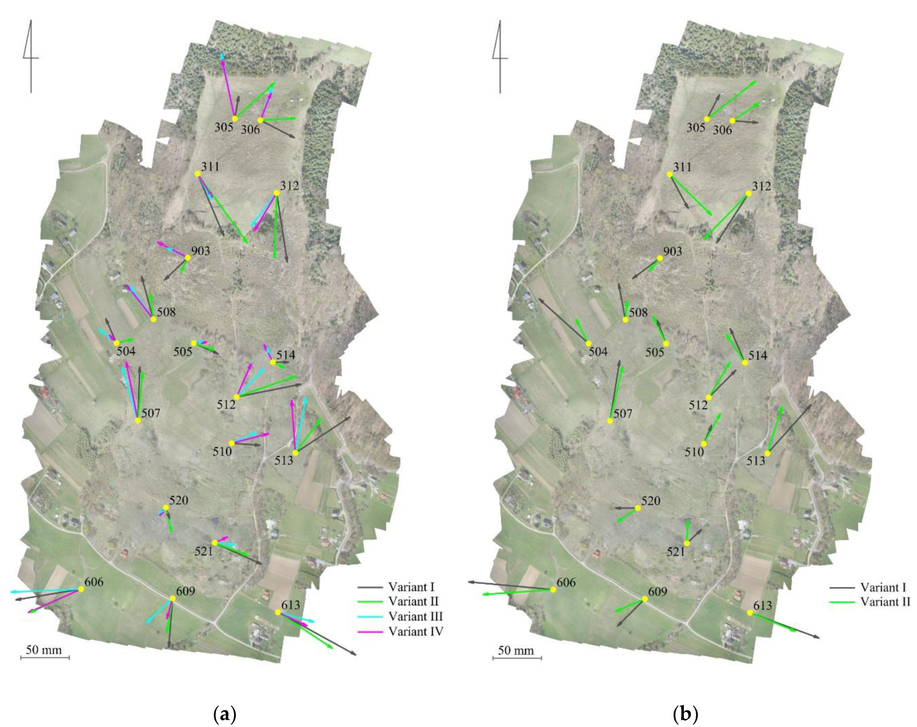
| Data Set | Coordinates of Check Points Measured on Photogrammetric Products | |||
|---|---|---|---|---|
| VARIANT 1 | VARIANT 2 | VARIANT 3 | VARIANT 4 | |
| Coordinates of check points surveyed using static GNSS | + | + | + | + |
| Coordinates of check points surveyed using RTK GNSS | + | + | − | − |
| Parameter | VARIANT 1 | VARIANT 2 | VARIANT 3 | VARIANT 4 | ||||||||
|---|---|---|---|---|---|---|---|---|---|---|---|---|
| ΔX | ΔY | ΔH | ΔX | ΔY | ΔH | ΔX | ΔY | ΔH | ΔX | ΔY | ΔH | |
| Average difference (mm) | −7 | 16 | −50 | −6 | 18 | 3 | 12 | −4 | −14 | 11 | −3 | 6 |
| Maximum difference (mm) | 55 | 80 | 82 | 49 | 60 | 73 | 67 | 37 | 43 | 60 | 38 | 95 |
| Minimum difference (mm) | −71 | −67 | 211 | −71 | −52 | −89 | −34 | −72 | −86 | −39 | −54 | −72 |
| Standard deviation (mm) | 36 | 35 | 84 | 34 | 28 | 48 | 29 | 26 | 44 | 30 | 23 | 42 |
| Parameter | VARIANT 1 | VARIANT 2 | ||||
|---|---|---|---|---|---|---|
| ΔX | ΔY | ΔH | ΔX | ΔY | ΔH | |
| Average difference (mm) | 10 | −3 | −52 | 11 | 0 | 1 |
| Maximum difference (mm) | 62 | 71 | 78 | 56 | 50 | 87 |
| Minimum difference (mm) | −51 | −87 | −206 | −47 | −72 | −79 |
| Standard deviation (mm) | 32 | 37 | 85 | 30 | 33 | 47 |
© 2018 by the authors. Licensee MDPI, Basel, Switzerland. This article is an open access article distributed under the terms and conditions of the Creative Commons Attribution (CC BY) license (http://creativecommons.org/licenses/by/4.0/).
Share and Cite
Puniach, E.; Bieda, A.; Ćwiąkała, P.; Kwartnik-Pruc, A.; Parzych, P. Use of Unmanned Aerial Vehicles (UAVs) for Updating Farmland Cadastral Data in Areas Subject to Landslides. ISPRS Int. J. Geo-Inf. 2018, 7, 331. https://doi.org/10.3390/ijgi7080331
Puniach E, Bieda A, Ćwiąkała P, Kwartnik-Pruc A, Parzych P. Use of Unmanned Aerial Vehicles (UAVs) for Updating Farmland Cadastral Data in Areas Subject to Landslides. ISPRS International Journal of Geo-Information. 2018; 7(8):331. https://doi.org/10.3390/ijgi7080331
Chicago/Turabian StylePuniach, Edyta, Agnieszka Bieda, Paweł Ćwiąkała, Anita Kwartnik-Pruc, and Piotr Parzych. 2018. "Use of Unmanned Aerial Vehicles (UAVs) for Updating Farmland Cadastral Data in Areas Subject to Landslides" ISPRS International Journal of Geo-Information 7, no. 8: 331. https://doi.org/10.3390/ijgi7080331
APA StylePuniach, E., Bieda, A., Ćwiąkała, P., Kwartnik-Pruc, A., & Parzych, P. (2018). Use of Unmanned Aerial Vehicles (UAVs) for Updating Farmland Cadastral Data in Areas Subject to Landslides. ISPRS International Journal of Geo-Information, 7(8), 331. https://doi.org/10.3390/ijgi7080331