1. Introduction
Three-dimensional city models (3DCMs) have become prominent in urban applications due to their ability to provide realistic scenes that can be easily perceived and understood [
1], as well as the technological improvements in hardware, software, and 3D building data acquisition to support 3D visualization [
2]. In urban planning, the 3DCM such as the one presented in [
3] provides alternative design plans which show the future city for urban planners to evaluate the architectural and aesthetic design of the city. There are also other applications of 3DCMs for exploring the past, present, and future of a city [
4], assessing the environmental equity in viewing environmental amenities (e.g., green space, water bodies, historical buildings, mountains) [
5] or accessing sunlight [
6], and evaluating multi-constellation Global Navigation Satellite System performance [
7].
While having multiple advantages in urban applications, reaching a truly functional 3DCM for urban applications has been hampered by the constant need to handle huge amount of 3D buildings. For example, the 3DCM of Charlotte, NC, contains approximately 370,000 3D buildings, or over four million polygons [
8]. The problem is made more acute when users attempt to interact with the 3DCM to explore different parts of a city, which involves constant panning and zooming.
To tackle this challenge, existing studies have resorted to multi-scale representations [
8,
9,
10,
11]. In these studies, important buildings such as landmarks, buildings in the focus areas where users are interested in, or buildings which are near to the view point are visualized with 3D buildings in high levels of details (LODs) [
12] while others are visualized in low LODs. Compared to representation of all 3D buildings in high LODs, the multi-scale visualization demands less data volume, which in turn improves the efficiency of visualization. Furthermore, its ability to show both 3D buildings in high and low LODs promotes visual contrast and enhances 3D buildings in high LODs, which helps its users catch important information more intuitively.
Realizing the aforementioned benefits, researchers have focused on approaches to generalize 3D buildings, which underpin the multi-scale visualization of a 3DCM. These approaches are designed and implemented according to the geometric and semantic characteristics of 3D buildings, and are thus 3DCM-dependent. At the infancy of the 3DCM, the 3D buildings are 2.5D as they only encompass ground plans and heights. The simplification of such 3D buildings essentially amounts to the generalization of 2D ground plans, which has been a crucial issue in cartography and extensively studied. For example, Regnauld [
13] proposed an approach that segments ground plans by criteria taken from Gestalt theory. Based on these criteria, the approach preserves the pattern of building set, and the similarities and the differences between groups of buildings to ensure the legibility of the simplified ground plans. In a similar vein, Li, et al. [
14] presented a method to group building ground plans. After grouping, several useful statistic measures, such as the sum of the building area, the mean separation, and the standard deviation of the separation of buildings are attached to each group. In addition, the proposed approach incorporates a number of well-developed algorithms to generalize these building groups according to the attached information so that multi-scale products are derived. Chang, et al. [
15] proposed a simplification method based on the principles of urban legibility which leverages road networks to cluster the ground plans. In this way, the legibility of the complicated urban environment is guaranteed at any level of simplification. Yang, et al. [
16] considered both Gestalt principles and urban legibility by introducing a new distance metric for grouping ground plans. A hierarchical tree is subsequently constructed to store multi-scale ground plans. The method facilitates the recognition of urban structures.
For the methods pertaining to least squares adjustment (LSA) or neural network, Sester [
17] presented a method for simplifying ground plans by using LSA. The advantage of this method is that it considers several observations as constraints when simplifying ground plans. Allouche and Moulin [
18] introduced neural network into map generalization to handle the challenging problem of detecting high-density regions which involve the same cartographic elements (e.g., ground plans). The approach allows the generation of different levels of grouping according to the scale on the map, and thus realizes the multi-scale representation of cartographic elements. Sester [
19] incorporated the previous algorithms to optimize generalization. Specifically, LSA is adopted for simplification and displacement of individual ground plans while self-organizing map and neural network are used for detection of high-density regions and preservation of object density during generalization.
Other than approaches based on Gestalt theory or LSA, Kada and Luo [
20] introduced techniques from the field of computer graphics, half-space modeling and cell decomposition, for ground plans simplification. The approach maintains the overall geometric characteristics of the ground plans after simplification which facilitates the recognition of buildings. Haunert and Wolff [
21] proposed an optimization method to simplify ground plans by minimizing the number of edges subject to a user-defined error tolerance.
More recently, technological advancement has made highly realistic 3DCMs with complex structures possible. Approaches for simplification of these 3DCMs can generally be divided into two types. One leverages both geometric information and semantic information during simplifying 3D buildings while the other only uses geometric information as many 3D buildings do not contain semantic information. With regard to methods depending on both information, Fan, et al. [
22] combined LSA with the semantics information encoded in City Geography Markup Language (CityGML) to simply 3D buildings. The advantage of their approach is that it leverages semantic information associated with geometric objects of 3D buildings to avoid merging of features of different objects. Fan and Meng [
23] extended their algorithm so that it can simplify not only simple structures but also complex cases where the ground plans consist of diverse and complicated structures such as non-rectangular and non-parallel shapes. Moreover, they focused on generalization of roofs by eliminating smaller roof features, simplifying roof polygons, and merging the simplified polygons. Further making use of semantic information, Zhao, et al. [
24] presented a mathematical morphology-based algorithm that simplifies the complex 3D buildings by semantic relationships, especially the structural connectivity in 3D buildings so as to guide and to guarantee the proper generalization of topological relations and semantics of 3D building components. This approach permits 3D buildings in multiple discrete LODs with consistent geometry, topological relations, and semantics.
As many 3D buildings have been made without semantic information, researchers also put lots of effort into simplifying 3D buildings based on geometric information alone. Studies by Forberg [
25] and Grabler, et al. [
26] presented early attempts of 3D buildings simplification that saw limited applicability as they can only process 3D buildings with orthogonal walls and non-orthogonal but vertical walls. Furthermore, these approaches could not locate components of 3D buildings which need to be simplified. Such limitations were overcome by the perception-driven simplification methods [
27,
28], which locate 3D building portions needed to be simplified based on rendered image analysis and use Human Visual System (HVS) to guide the simplification of 3D buildings.
Other methods focus on dealing with local or global structures during simplification of 3D buildings. With regard to methods emphasizing local structures which indicate local characteristics of 3D buildings, Jiang, et al. [
29] proposed a feature preservation method based on cell clustering and surface reconstruction which involves three steps. First, 3D buildings are voxelized into cells. Second, boundary cells are extracted and a cell binary tree is constructed. Finally, the simplified 3D buildings are reconstructed based on a modified dual contouring algorithm. Similarly, Sun, et al. [
30] presented a structure-preserving algorithm, which also voxelizes 3D buildings into cells. Points are then sampled at the surface of cells. At the second step, the sampled points are classified for the convex decomposition of 3D buildings. At the third step, the simplified 3D buildings are obtained by combining the convexes. Even though these two approaches preserve features and structures of 3D buildings, it remains challenging to identify various structures. To tackle this challenge, Li, et al. [
31] proposed a structural simplification method, which uses convex/concave analysis to extract three types of structures: embedded structures, compositional structures, and connecting structures. Specific rules are made for simplification of geometric structures, and 3D buildings are simplified progressively.
With regard to global structures which represent overall appearance of 3D buildings, Kada [
32] proposed an algorithm driven by the major planes (i.e., global structures), which demonstrate the overall appearance of 3D buildings. This algorithm could simplify complex 3D buildings while preserving their overall appearance with the aid of semantic information contained in 3D buildings. Noting the limitations of being unable to process 3D buildings without semantic information and inspired by the idea of simplifying 3D buildings through emphasizing global structures, we provide an integrated means to simplify high-fidelity 3D buildings with either sloped or flat roofs using only geometric information. It aims to represent the overall appearance of 3D buildings with a minimum number of meshes. The rest of this paper is structured as follows.
Section 2 describes our approach for simplifying 3D buildings.
Section 3 shows the simplification results of 3D buildings using the proposed approach. The demonstration focuses on 3D buildings in Autodesk 3ds max format [
33] as the format is based on triangular meshes with flexibility to represent high-fidelity 3D buildings in arbitrary shapes.
Section 4 discusses the various studies of urban issues underpinned by simplification approaches.
Section 5 concludes our approach and provides future direction.
2. An Integrated Simplification Approach for 3D Buildings
The proposed integrated simplification approach for 3D buildings handles 3D buildings regardless of the presence or absence of semantic information. It is designed specifically not to rely on semantic information, such as that in the CityGML, to achieve the aim of simplification that represents the overall appearance of 3D buildings with a minimum number of meshes. This design choice is made because many 3D buildings still carry only geometric information, rather than geometric and semantic information combined.
The proposed simplification approach integrates the treatments of the sloped and flat roofs of 3D buildings under the notion of global features. Here, global features refer to either roofs or walls which contain geometric information to reconstruct a 3D building representing the overall appearance of the corresponding original counterpart. For a 3D building with sloped roofs, the global features must be the roofs because they contain the geometric information to construct walls. With the roofs and constructed walls, the 3D building could be reconstructed. For a 3D building with flat roofs, the global features could be either roofs or walls because roofs and walls could be used to construct each other. In the proposed algorithm, walls are chosen as the global features for our purpose because the area of walls is needed as input to simplify a 3D building with flat roofs.
In this approach, only global features need to be simplified while others are constructed from global features. For example, for a 3D building with sloped roofs whose global features are roofs, only roofs are simplified and walls are constructed from roofs. In this way, the computation is much more efficient compared to simplifying both roofs and walls. Furthermore, as individualized algorithms are designed for these two types of 3D buildings based on their geometric characteristics, the approach could simplify the 3D buildings in a more effective manner.
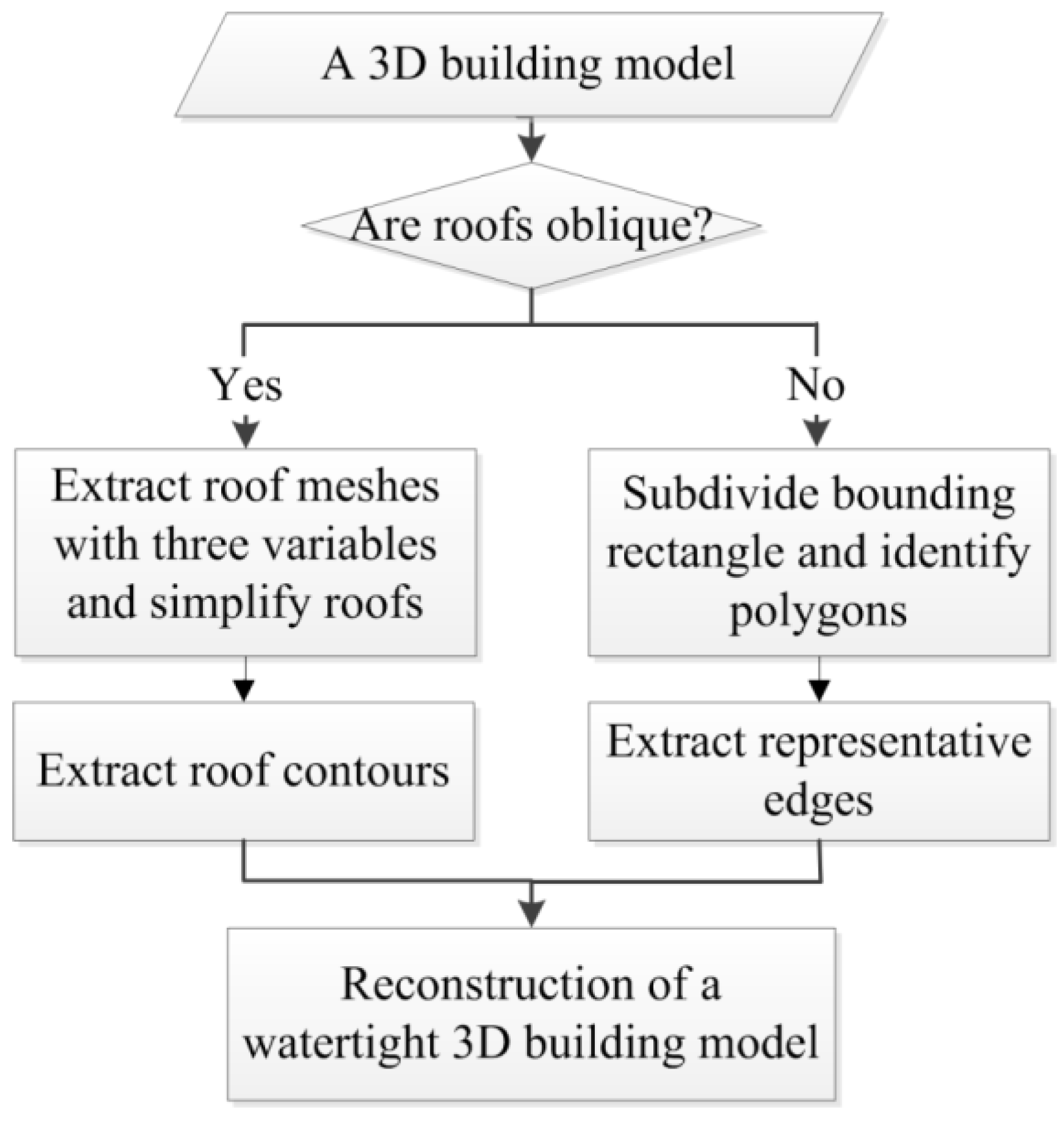
Figure 1 shows the flowchart of the proposed approach. The first step detects the roof type of a 3D building. Based on the result of the first step, the proposed approach chooses a corresponding branch for simplifying a 3D building. For a 3D building with sloped roofs, the simplification process will focus on developing roof contours. For a 3D building with flat roofs, the simplification process will leverage topological attributes to develop representative edges. In the subsections below, the details of each step will be elaborated.
2.1. Detect Roof Type
The proposed approach detects the roof type of a 3D building by examining the height, area, and slope of all its meshes. For a mesh to be identified as a sloped roof mesh, its lowest vertex has to be higher than a critical height, area has to be larger than a critical area, and slope has to be within an interval. In this article, the critical height is set to be one third of the height of the 3D building and the critical area is 25.0. The interval is between 0.0 and 45.0 degrees. These critical values and interval are determined empirically with respect to the size of 3D buildings, which works well for the 3D buildings we have tested. The identification process repeats until all meshes are examined. If the proposed approach identifies more than four meshes, the mesh number of the simplest sloped roof (e.g., pyramid hip), the building is considered to have sloped roofs. Otherwise, it is considered to have flat roofs.
2.2. Simplify a 3D Building with Sloped Roofs
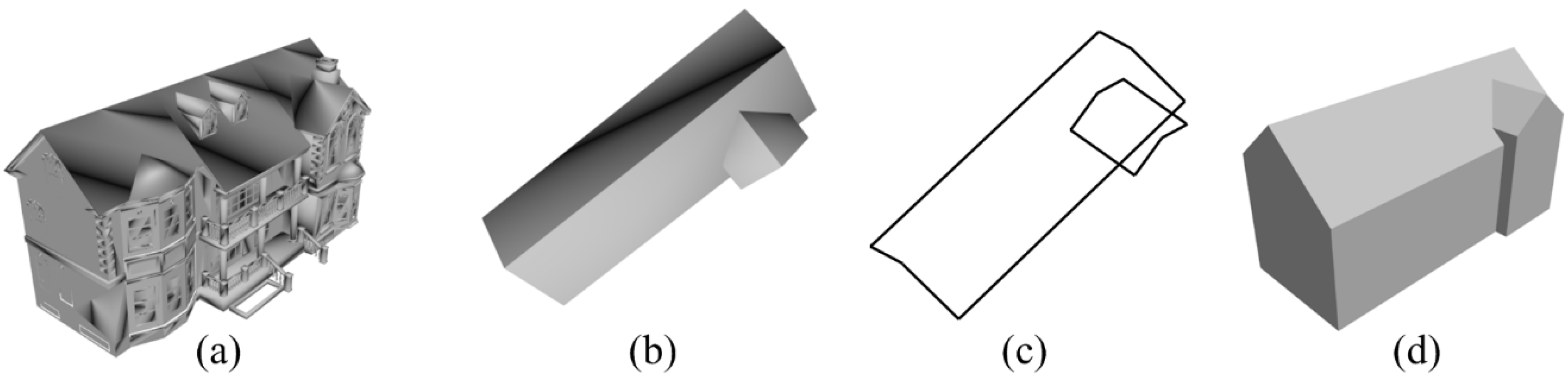
Once a 3D building with sloped roofs is identified, the simplification algorithm uses the roof meshes extracted in the step of identifying roof types to simplify roofs, extract roof contours, and reconstruct a watertight 3D building. In
Figure 2a–d, an example of a complex 3D building with four sloped roofs and the results of carrying out the proposed algorithm are presented. Below, these three additional steps, i.e., simplification of roofs, extraction of roof contours, and reconstruction of a watertight 3D building, are elaborated.
- (1)
Extraction and Simplification of Roofs
Roof meshes extracted while detecting roof types are used for the simplification of roofs. Actually, during the extraction of roof meshes, the roofs have already been simplified to some extent as small meshes representing negligible structures such as chimneys, trivial roofs are removed. For further simplification, the proposed algorithm includes four steps. First, the classification of extracted roof meshes is carried out. Roof meshes, which locate at the same plane, are classified into one group. Vertexes of roof meshes in each group are extracted and stored. Furthermore, the planes in which each group of roof meshes locate are constructed and stored. Second, a minimum convex hull (MCH) algorithm is applied to each group of vertexes to simplify the roof meshes. Specifically, the MCH algorithm is conducted in 2D, i.e., the height value of each vertex does not participate in the acquisition of MCH, to reduce computation load. In order to acquire the height values for the vertexes of MCH, a vertical ray extending from each vertex of MCH toward the direction of roof (i.e., upward) is constructed to intersect with the corresponding plane, in which this group of roof meshes locate. Third, a minimum bounding rectangle (MBR) algorithm is applied to the result of running MCH. If the overlapping area of MCH and MBR is larger than critical percent, which is set to be 80% in this article, MBR is used as the simplified polygon to represent the roof meshes. Otherwise, the MCH is used. Fourth, the MCH/MBR for each group is divided into triangular meshes to meet the data format. The triangular meshes are the final roof meshes.
- (2)
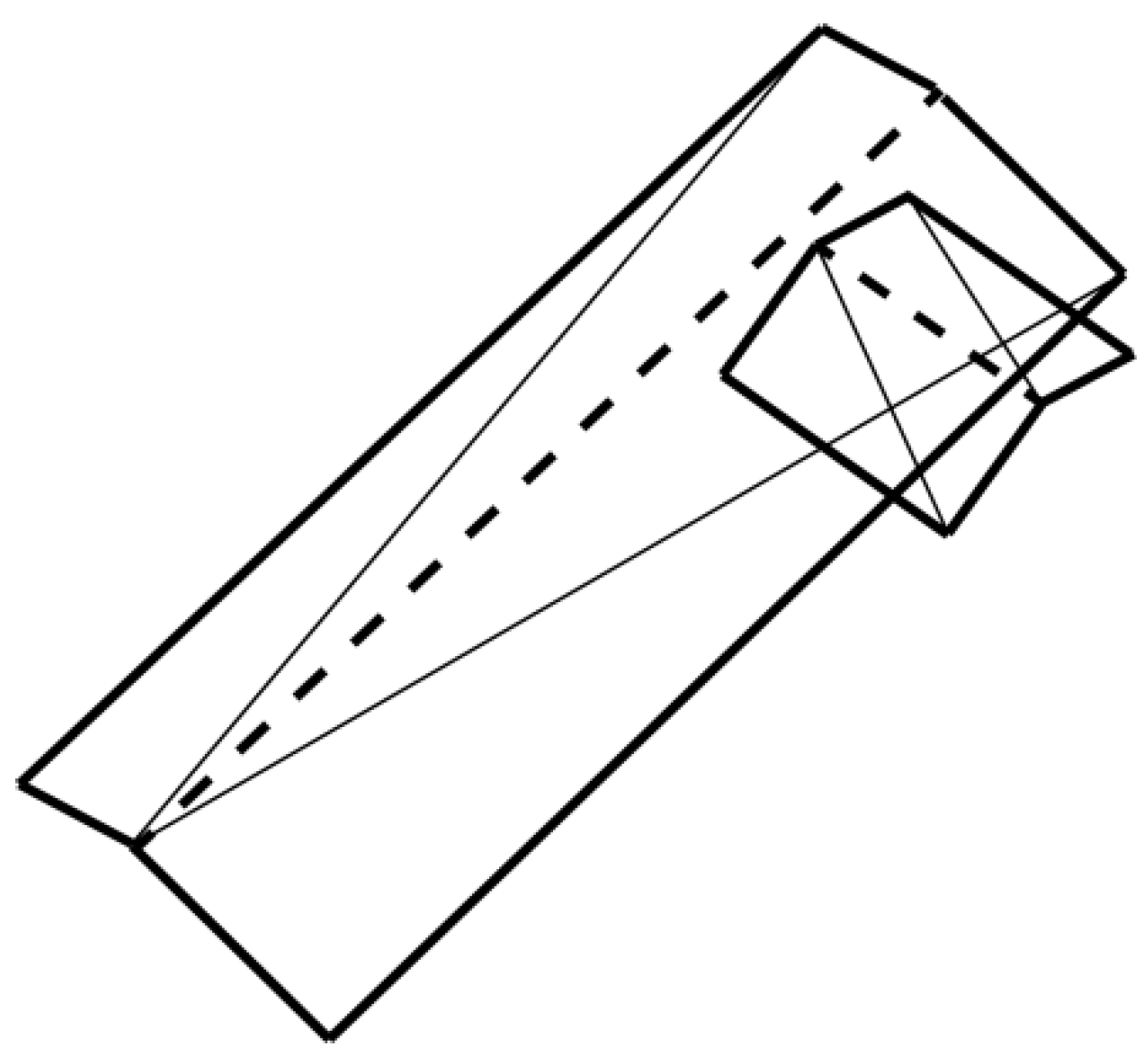
Extraction of Roof Contours
Roof contours refer to specific roof edges used to construct wall meshes. The reason to extract roof contours from final roof meshes instead of using all roof edges to construct wall meshes is to save data volume. In addition, regular roof edges do not influence the overall appearance of the reconstructed 3D building. The method adopted here looks for edges that fit two removal criteria. The first criterion takes advantage of the exact nature of these edges, i.e., each edge in the roof contours is close to a wall or even shared with a wall, and therefore at least one of the two endpoints forming such an edge must be the lowest vertex of the roof mesh containing such an edge because walls are under roofs. In this way, the “ridge” of the roof (shown in dashed lines in
Figure 3) could be removed. The second criterion identifies the longest edge of a mesh edge (shown in thin lines in
Figure 3). As any such edge is shared by two roof meshes, it is definitely not the roof contours and has to be removed. Note that
Figure 2b and
Figure 3 display the same data in different modes.
Figure 3 is the wireframe mode while
Figure 2b is the mesh mode.
- (3)
Reconstruction of a Watertight 3D Building
Roof contours achieved in the previous step are used to reconstruct a watertight 3D building which means that there is no gap among its wall and roof meshes. The reconstruction of a watertight 3D building assumes that the height of the ground is zero, and then orthographically projects the roof contours to the ground to generate the corresponding ground contours (i.e., ground plan or ground boundary). Each edge in roof contours and its corresponding orthographically projected edge in ground contours are then used to construct a rectangular mesh that represents a wall. As the projection used in the proposed method is orthographic, the constructed wall is vertical to ground which achieves the effect of rectifying non-vertical walls to be vertical ones. In other words, the proposed method could handle 3D buildings with non-vertical walls. Each rectangular mesh that represents a wall is later subdivided into two triangular meshes to comply with the Autodesk 3ds Max format. Combining the constructed wall meshes with the roof meshes which are used to extract roof contours, a watertight 3D building is reconstructed.
2.3. Simplify a 3D Building with Flat Roofs
The proposed method simplifies a 3D building with flat roofs based on its walls for two reasons. First, its walls are the global features that serve as the basis for reconstructing the 3D building. Second, the area of walls is needed as input in the process of simplifying the 3D building. The process involves three steps: (1) subdivision of bounding rectangle of the building ground plan based on wall meshes and identification of polygons locating inside the 3D building; (2) extraction of representative edges from the polygons; and (3) reconstruction of a watertight 3D building.
Figure 4a–d shows an example of a 3D building with flat roofs and the result of each step.
- (1)
Subdivision of Bounding Rectangle of the Building Ground Plan and Identification of Polygons Located Inside the 3D Building
This step starts with extracting the wall meshes of the 3D building. It is a straightforward process by identifying meshes with slopes between 60 and 90 degrees. The wall meshes thus identified are subsequently sorted by area in descending order. The first mesh in the collection of sorted wall meshes is considered to be the most representative wall mesh of the 3D building as it is visually prominent with the largest area.
The collection of sorted wall meshes is then subject to major plane fitting. The procedure starts with the first mesh in the collection. It involves two steps, i.e., constructing the major plane of the mesh, which is represented by Ax + By + Cz + D = 0, from the coordinates of its three vertices, and examining all the subsequent meshes in the collection whether they are within a pre-defined buffer radius. Those within the buffer region are removed from the collection as they can be considered as minor features of the buildings, and the collection is updated. Mathematically, the buffer region of a major plane is between Ax + By + Cz + D1 = 0 and Ax + By + Cz + D2 = 0, where D1 = D − Dbuf, D2 = D + Dbuf, and Dbuf denotes buffer distance which could be pre-determined by users based on their understanding to the 3D building. The plane equation needs to be normalized by ensuring that A2 + B2 + C2 = 1 so that Dbuf can be compared in different plane equations. A mesh inside the buffer region must satisfy the condition (Ax + By + Cz + D1) × (Ax + By + Cz + D2) < 0. After completing the first mesh, the whole procedure repeats for each of the remaining meshes in the updated collection until the last mesh is examined.
The major planes thus constructed form the basis from which major lines can be extracted. This is done by dropping the y term in the major plane equation Ax + By + Cz + D = 0. The reason to convert major planes to major lines, i.e., from a 3D equation to a 2D equation, is to improve computational efficiency in the following steps. In
Figure 4b, the major lines thus constructed are all the edges.
The major lines thus obtained are then used to subdivide the bounding rectangle of the building ground plan. The bounding rectangle is retrieved by first obtaining the bounding box of the 3D building and then dropping the height dimension. To subdivide the bounding rectangle, the major lines of the 3D building developed in the previous step go through an intersection process to subdivide the bounding rectangle gradually.
As not all the polygons resulting from intersection of the major lines and the bounding rectangle are located inside the 3D building, it is necessary to identify them. The process involves three steps. First, meshes of the 3D building excluding wall meshes are extracted. Second, the centroid of each polygon is calculated. Third, a vertical ray extending from each center point toward the direction of roof (i.e., upward) is constructed. If the vertical ray intersects with any one of the extracted mesh in the step of identifying roof types, which means its corresponding polygon locating inside the 3D building, the polygon is preserved, as well as the height of the intersection point. We call these polygons interior polygons. If the vertical ray intersects with more than one extracted mesh, only the largest height value is preserved. The preserved polygons and their corresponding heights are used to reconstruct the 3D building. The identified result is shown in
Figure 4b.
- (2)
Extraction of Representative Edges
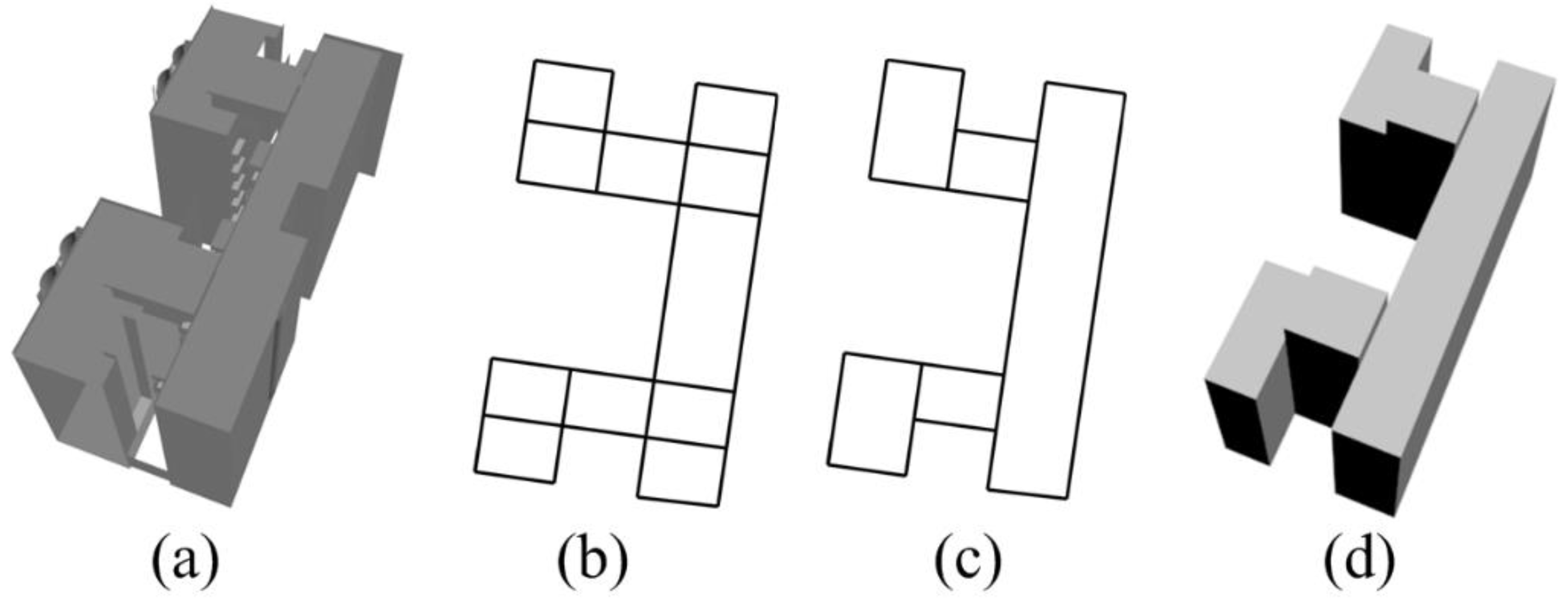
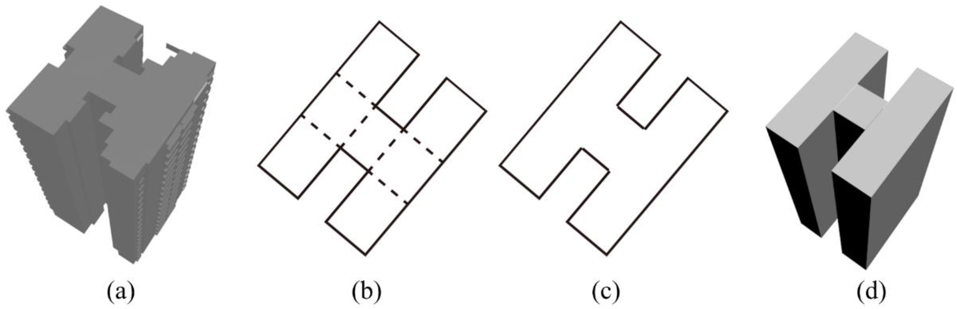
Representative edges of the polygons identified in the previous step are used to construct wall meshes of the 3D building. Here representative edges refer to the edges whose constructed wall meshes influence the overall appearance of the reconstructed 3D building. In
Figure 5 where a sample building with roofs of uniform height is shown (
Figure 5a), the representative edges are symbolized with lines while the normal edges are symbolized with dashed lines (
Figure 5b). Once identified, these representative edges are extracted (
Figure 5c) for constructing wall meshes. Note that the edges symbolized with dashed lines are characterized by being shared by two adjacent polygons. As can be seen from
Figure 5b, normal edges do not influence the overall appearance of the reconstructed 3D building (
Figure 5d) as their constructed wall meshes locate inside the reconstructed 3D building. For the 3D building with uniform height, the representative edges are these composing the ground plan as their constructed wall meshes show part of the overall appearance of the reconstructed 3D building.
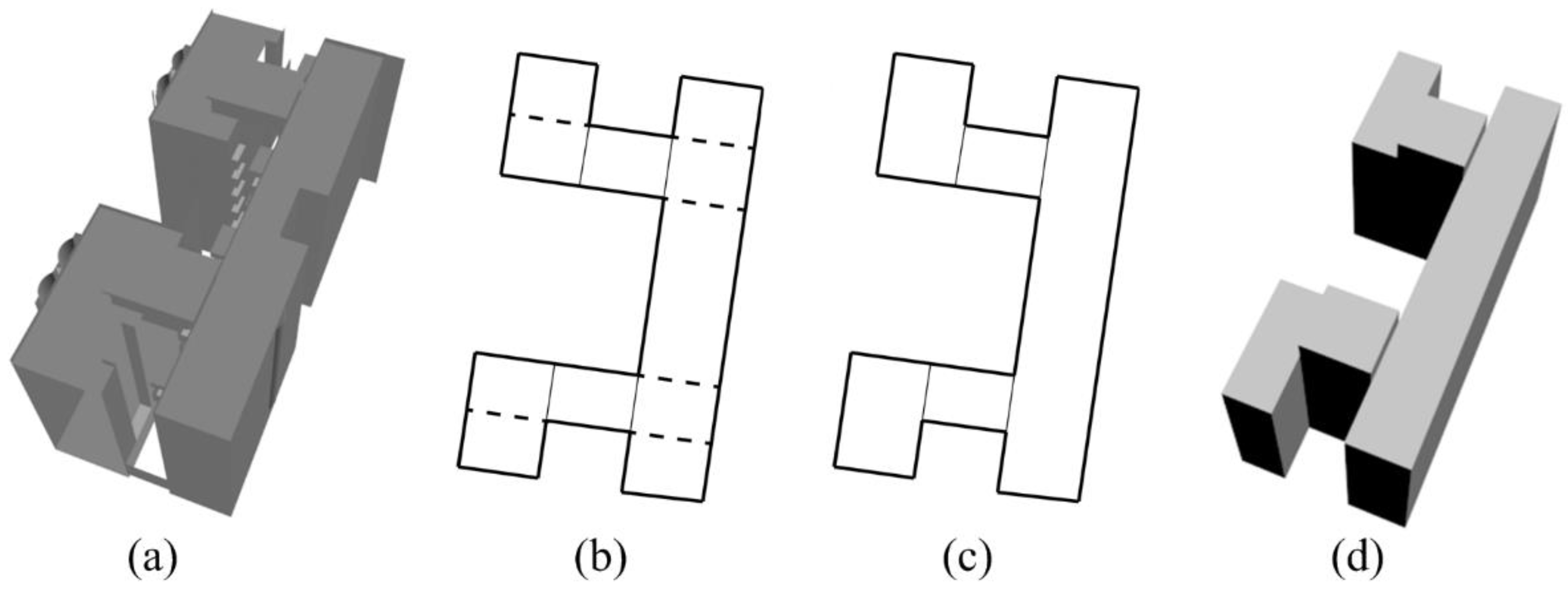
While the shared edges for building roofs with uniform height are normal edges, they may be representative edges for building roofs with multiple heights.
Figure 6 shows one such example. Both edges symbolized with thin lines and dashed lines in
Figure 6b are shared by adjacent polygons. However, edges symbolized with thin lines are representative edges while edges symbolized with dashed lines are normal edges. The reason is that these edges symbolized with thin lines are at the locations where adjacent polygons with different heights meet. From reconstructed 3D building in
Figure 6d, edges symbolized with a thin line are representative as their constructed wall meshes represent part of overall appearance. Without the wall meshes constructed by the edges symbolized with thin lines, the 3D building will have “holes”. Image that the wall meshes under the edges symbolized with thin lines in
Figure 6d are missing, then the 3D building is not closed. There will be gaps under the edges symbolized with thin lines which are termed “holes”.
The method to extract representative edges is as follows. First, we design a data structure for edges, which includes a starting point, an ending point, and a height. The reason to construct a new data structure is that these three variables in the data structure can store necessary values for the reconstruction of a watertight 3D building in the following step. Heights are included for edges to reconstruct a 3D building as edges only have 2D information. Second, the method extracts the two representative edge types highlighted above, i.e., edges of a ground plan or edges whose two shared polygons have different heights. To extract the first edge type, topological attributes that edges composing a ground plan belonging to only one polygon are utilized. Specifically, when identifying whether an edge belongs to a ground plan, the method counts the number of polygons containing this edge. If the number is one, we extract this edge (i.e., store the start point and end point of this edge in edge structure) and store the height of the polygon in the edge structure. Otherwise, it is an edge shared by two adjacent polygons. For such an edge, only the one shared by polygons with different heights is extracted, and the bigger height is stored in the edge structure.
- (3)
Reconstruction of a Watertight 3D Building
Reconstructing a watertight 3D building with flat roofs is rather similar to that with sloped roofs. It is also based on the assumption that the height of a ground plan is zero. The representative edges extracted at the previous step are used to reconstruct the 3D building. As they contain the height of walls, we could establish the edges of roof contours. For example, the height of an edge in the ground plan is zero. By editing the height to be equal to the height stored in edge structure, the corresponding edge belonging to roof contours is constructed. Then the edge in the ground plan and its corresponding edge in the roof contours can be used to construct wall meshes for the 3D building. These two edges form a rectangular mesh which is vertical to ground. It achieves the effect of rectifying non-vertical walls to be vertical ones. In other words, the proposed algorithm could rectify 3D buildings with non-vertical walls. This rectangular mesh is subdivided into two triangular meshes to match Autodesk 3ds Max format. When constructing the flat roofs, we use the interior polygons containing heights identified in step (1). These polygons also need to be converted into triangular meshes.
3. Experimental Results
Two case studies were carried out to test the effectiveness of the proposed simplification approach. The first case study evaluates the ability of the proposed approach in simplifying individual buildings at varying levels of complexities while preserving their major appearance. These typical 3D buildings are freely available online (e.g., 3D Warehouse [
34]). The second case study evaluates the ability of the proposed approach in handling various structures of buildings over a section of a city. Three-dimensional buildings around Shenton Way, Singapore created by MAGIC [
35] are used for the stated purpose.
Given different scales of the two case studies, i.e., one at the individual 3D building scale while the other is at the city scale, the two case studies demonstrate different capabilities of the proposed simplification algorithms. In the first case study, the 3D buildings in high LOD (e.g., LOD3) which preserves the most characteristics of overall appearance are demonstrated individually. The ability to preserve the overall appearance can be readily identified by comparing a 3D building pair composed of the simplified 3D building in LOD3 and its original counterpart side-by-side and from two views: (1) a top-down view that shows the simplification of roofs and ground plans and (2) a street view that shows the simplification of roofs and wall structures. In the second case study, the cityscape in multi-LODs is demonstrated in street view for observing changes in overall appearance. Such choice of visual comparison is based on the fact that recognizing 3D building groups depends more on the preservation of appearance and patterns of 3D building groups rather than the appearance of individual 3D buildings.
3.1. Simplificaiton of Typical 3D Buildings
In the first case study, samples of the 3D buildings with sloped roofs and flat roofs were examined. Recognizing these two roof types is important as they determine the global features, i.e., the roof for 3D buildings with sloped roofs and the wall for 3D buildings with flat roofs, on which the proposed simplification algorithm operates. The test examples examined thus involve varying levels of roof and wall complexity.
For the 3D buildings with sloped roofs, three examples with different roof complexity are presented (
Figure 2,
Figure 7 and
Figure 8). For clarity, the original 3D buildings and the simplified counterparts are shown in both street view and top-down view. For the 3D building in
Figure 2, in terms of the roof complexity, it involves four sloped roofs in two orientations, one chimney, and two small sloped roofs. In terms of wall complexity, the 3D building involves walls, fences, stairs, windows, and inner structures. For such a complex 3D building, any simplification approaches that attempt to handle the roof and wall together would inevitably be time-consuming. As the proposed algorithm works with global features, i.e., roofs for the 3D buildings with sloped roofs, it would be more efficient. After simplification, the minor and local structures such as the chimney and the small sloped roofs are removed while the dominant and global structures such as the roofs in two orientations which show the overall appearance of 3D buildings are preserved. The complicated walls are represented with simple structures. For the 3D building in
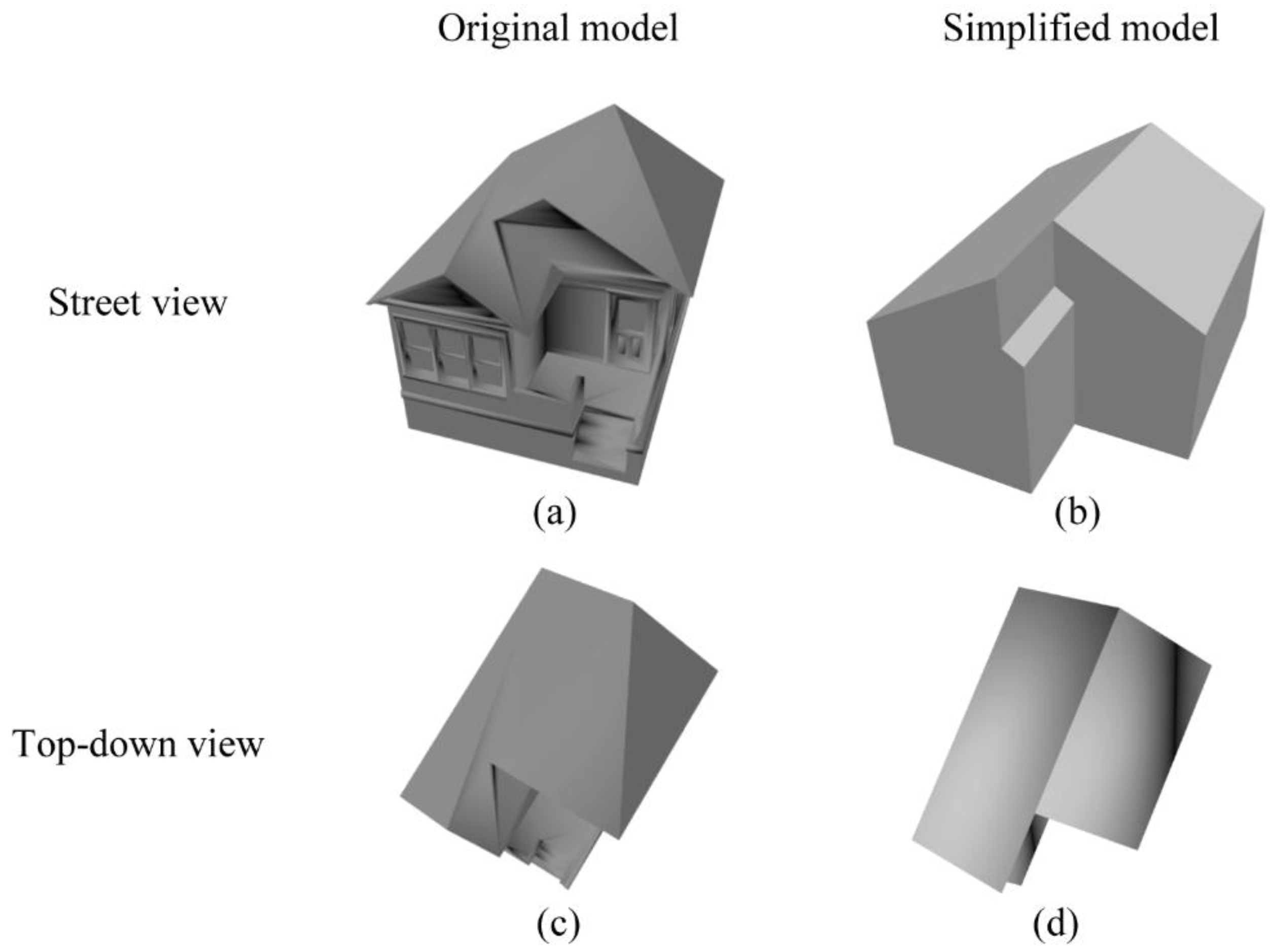
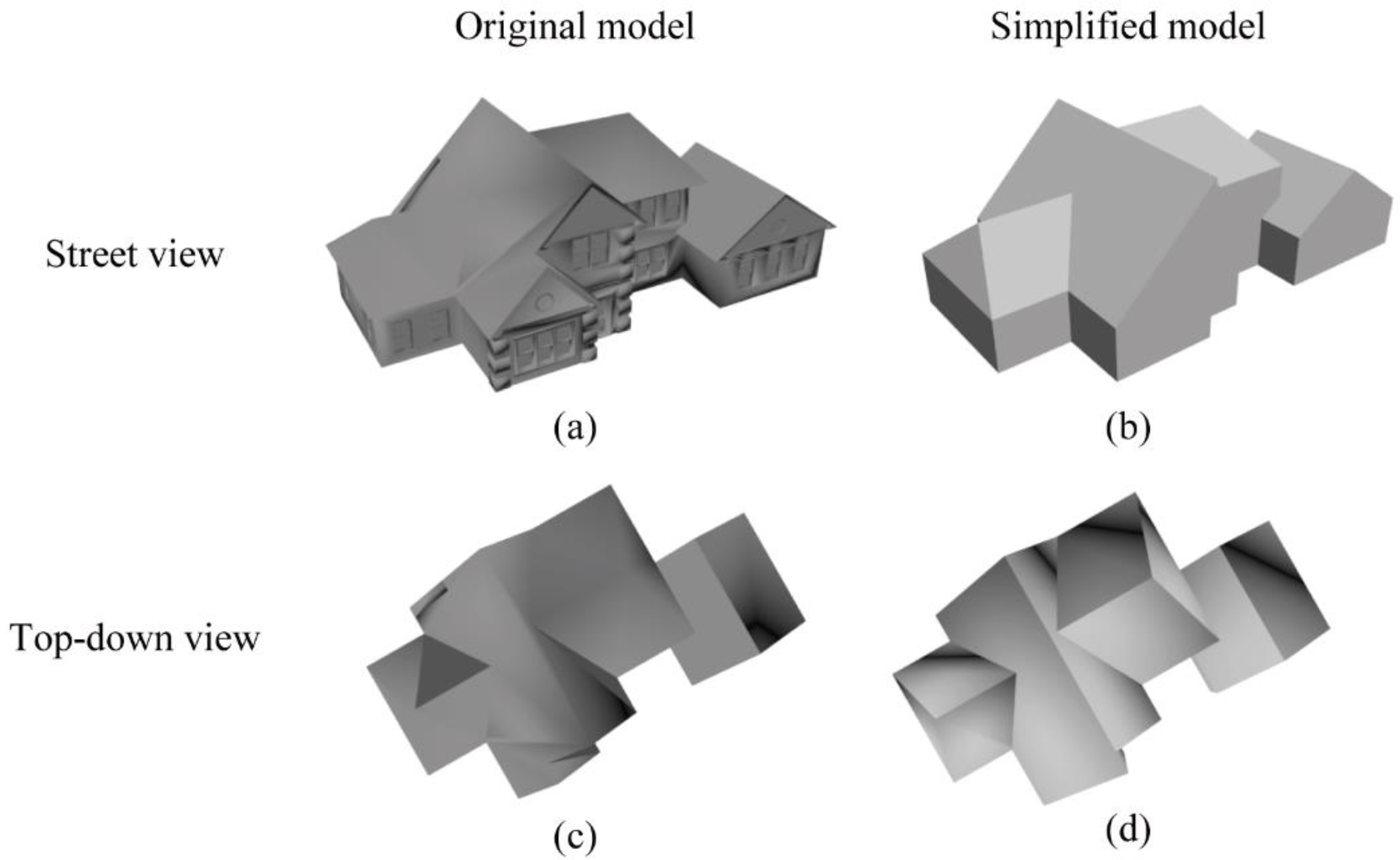
Figure 7, in terms of the roof complexity, there are four roofs in two orientations. The structures of each roof are different, which are gable and hip. In terms of wall complexity, it encompasses walls, windows, doors, and various trivial structures. After simplification, the roofs are preserved while the complex structures of walls are replaced with simple walls.
Figure 8 shows a 3D building that involves two roofs in identical orientation. By comparing the roofs of the original 3D building with its simplified counterpart, especially in top-down view, it can be seen that non-convex roofs (left part in
Figure 8c,d) are simplified to be their MBR. Moreover, the highly simplified structures are the walls even though the proposed algorithm does not really touch geometric data for representing the walls.
For 3D buildings with flat roofs, three examples with different wall complexities are demonstrated (
Figure 5,
Figure 9 and
Figure 10). In
Figure 5, the 3D building involves two blocks with the same height and multiple balconies. After simplification, the two blocks are preserved while the balconies are removed.
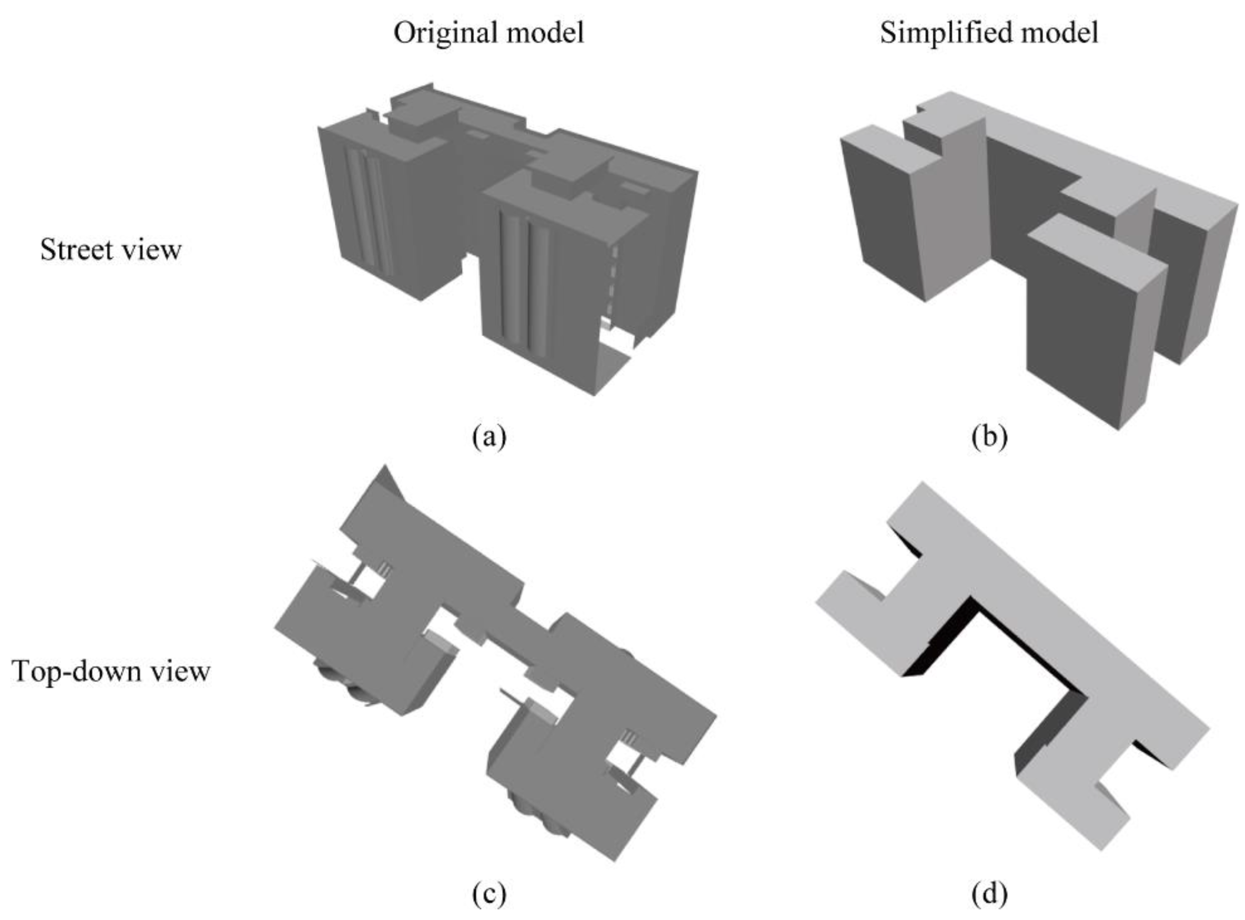
Figure 9 shows a 3D building that includes multiple blocks with different heights, multiple balconies, and half-cylinder structures. Furthermore, a surface of one block is missing, which causes a hole in the 3D building and thus represents a case of incomplete data. However, the proposed algorithm can still simplify it with a satisfactory result. The robustness of the proposed algorithm is thus validated. Here “satisfactory result” means that the overall appearance (i.e., main bodies) of the 3D building is preserved after simplification. Specifically, the volume overlap of two 3D buildings (i.e., the original and simplified 3D buildings) is high. In
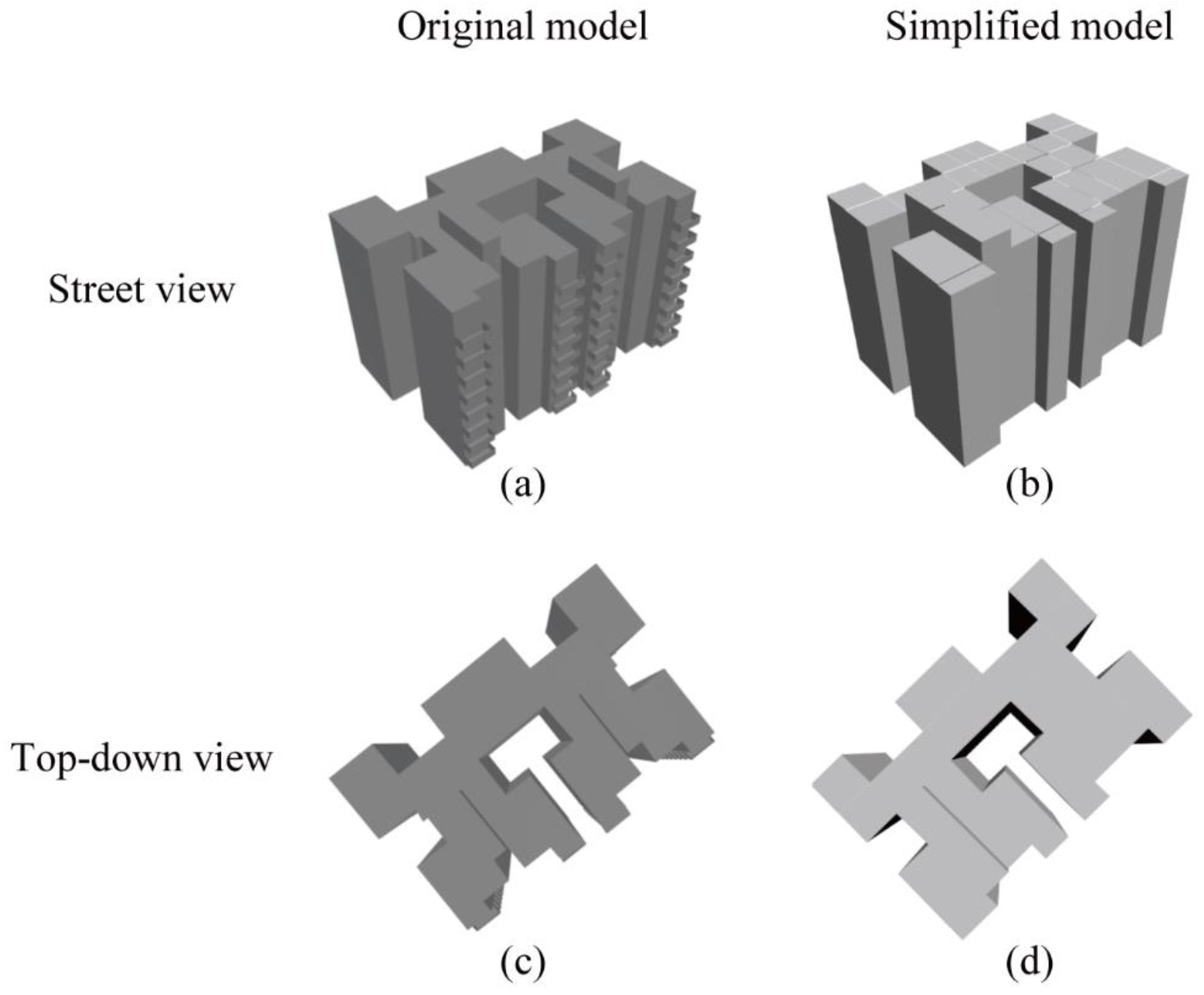
Figure 10, the 3D building involves multiple blocks, whose orientations constantly change like a maze, and multiple balconies. After simplification, the “maze” is maintained.
Generally, for 3D buildings with sloped or flat roofs, the simplified 3D buildings represent the overall appearance of the original counterparts by preserving their main bodies and removing detailed features according to the comparison of the simplified 3D buildings and the original counterparts.
Table 1 shows the reduction of data volume measured by the numbers of vertices and triangular meshes. From the table, the minimum data volume reduction rate for all tested models is 47.0% in
Figure 10. This is likely because the original 3D building does not include detailed features. Except this 3D building, the data volume reduction rates of other 3D buildings are all above 87.0%. Specifically, 3D buildings in
Figure 2 and
Figure 7,
Figure 8 and
Figure 9 achieve a data volume reduction rate of 98.3% and above. By observing the features of 3D buildings displayed in the corresponding figures, it can be inferred that such a huge data volume reduction is owed to the fundamental rule of simplification of 3D buildings: representing the overall appearance of 3D building with the least number of meshes as possible, especially for these original 3D buildings containing rather complex and detailed features. By simplification, these complex and detailed features, which occupy huge data volume, are removed while the main bodies of the 3D buildings are preserved.
3.2. Simplification of Cityscapes
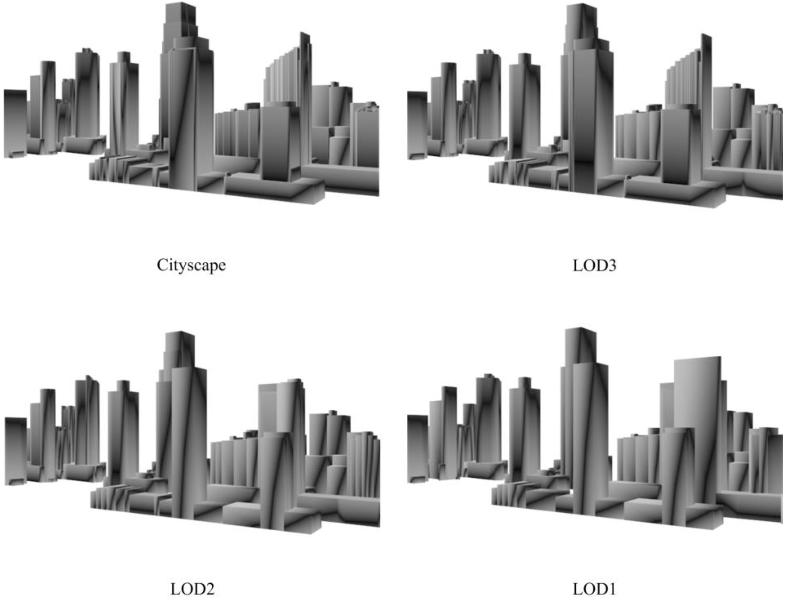
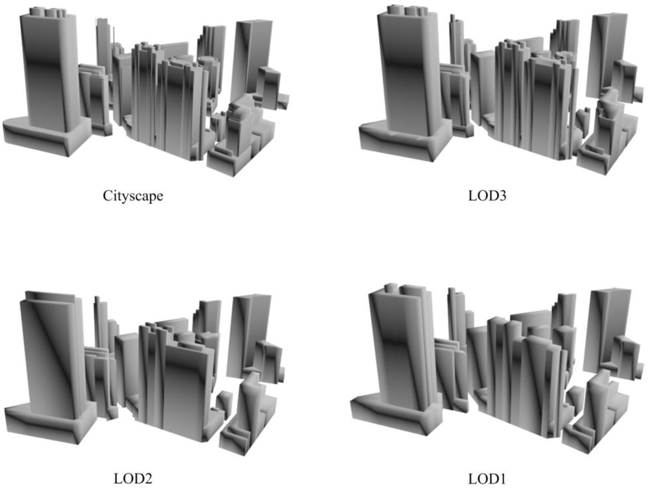
The second case study examined the multi-scale simplification of a cityscape (i.e., 411 3D buildings in Shenton Way, Singapore). The case study aims to evaluate the performance of the proposed approach at the city scale, measured again both by its capability to retain visual appearance while achieving substantial data reduction rate.
Figure 11 and
Figure 12 show two examples of multi-scale simplification of the cityscape. Referring to the original scenes, the three simplified scenes in each subfigure show no obvious visual difference, suggesting that the proposed approach is able to retain overall visual appearance of the cityscape even with a low LOD (e.g., LOD1). Compared to visualizing the cityscape with bounding boxes of original 3D buildings or simple cells (Chang et al., 2008; Glander and Döllner, 2009), the multi-scale cityscape acquired by our approach is much more realistic. The data volume reduction rate ranges from 61.1% to 97% (
Table 2). Based on the visual results in
Figure 11 and
Figure 12, and statistics results in
Table 2, the ability of the proposed approach is validated that it can preserve the overall appearance of 3D buildings while reducing the data volume to a large degree.
4. Discussion of Studies of Urban Issues Underpinned by Simplification Approaches
The capability of simplification algorithms to automatically generate multi-scale 3DCMs in which buildings in multiple LODs are modeled and stored have vast potentials in supporting the studies of urban issues [
36]. To provide a context in which simplification algorithms are useful, a brief discussion is provided below on the technical implementations that leverage 3DCMs to improve data query, data retrieval, and data representation (e.g., spatiotemporal modeling) for urban issues, as well as the use of 3DCMs for studying various topics related to urban sustainability.
With respect to the technical implementations leveraging 3DCMs, in the study of cultural heritage that requires the use of various complicated data in the 3DCM, a database schema was proposed to organize data and to support data queries by geometric, semantic, and spatial properties [
37]. In addition to specific applications, technical improvements for data queries or management, which can be adopted in general applications, were also implemented. Space-filling curves (3D Hilbert curves) for data representation in the 3DCM were proposed to improve the efficiency of data retrieval by optimizing 3D adjacency, 3D indexing, and nearest neighbor information [
38]. Similarly, in order to improve the ability to maintain the consistency of data in the 3DCM and thus further accelerate data retrieval for various applications, a 4D model that links identical objects in different LODs in the 3DCM was developed [
39]. For spatiotemporal modeling, by modeling and comparing a cityscape at different time snapshots, a final 3D building change model map, which shows the destructed and newly constructed buildings, can be acquired. Based on the 3D change map, the volume and surface of the building changes were quantified [
40]. In addition, a spatiotemporal GIS model was built to study changes in the physical form of cities by visualizing the dynamic transition of the 3DCM over time [
41]. For general variation exploration, 4D maps were designed to demonstrate spatiotemporal environmental phenomena, which support explorative research [
42]. A new concept ‘dynamizer’ was proposed to support the injection of highly dynamic and time-varying properties into the 3DCM, so that variation of attributes could be represented for exploration [
43]. Technically, methodological principles were presented to construct past urban landscapes in order to analyze urban changes and connect transformation processes [
44].
With respect to various applications in urban sustainability, massing cityscapes (i.e., 3D buildings in low LOD) can be used for urban design and urban planning [
45]. For solar radiation estimation in urban environments, instead of being limited by 2D surfaces (e.g., flat roof surfaces), the introduction of the 3DCM, coupled with its ability to provide data at the appropriate LOD, enabled the development of a new 3D solar radiation model that considers both the building roofs and walls [
46]. Furthermore, for effective planning of solar panel constructions or passive energy measures, solar income was considered in multiple scales. At a regional scale, the 3DCM in low LOD was used for rough solar income assessment while at the household scale, the 3DCM in high LOD was used for an accurate estimate [
47]. Based on the semantic and geometric information in the 3DCM, heat demand estimation is made possible by considering energy needed for each building at the large scale (e.g., national scale) [
48]. Furthermore, a more comprehensive study using building physical properties, local weather conditions, and its interactions with neighboring buildings to assess heat demand was conducted. Specifically, for solar radiation and heat demand estimation, the surface materials of buildings and building physics are important factors as they directly influence the absorption and release of energy. 3DCMs also see their applications in urban sustainability through the study of urban morphology and their impact on urban transportation [
49] and urban climate [
50].
5. Conclusions
Multi-scale 3DCMs have demonstrated their great potential in studying various urban issues. Simplification of 3D buildings, which underpins the construction of multi-scale 3DCMs and thus further supports urban studies, is undoubtedly crucial. In addition, simplification of 3D buildings is critically important for the visualization of urban environment as 3D buildings have become more “real”, i.e., in high-fidelity, and thereby come with huge data volume. It helps reduce data volume while retaining the overall visual appearance of these 3D buildings, either in the level of individual buildings or a city. With simplification approaches, urban environments could be visualized in an efficient and realistic manner thus potentially demonstrating their capability for serving various purposes in decision making.
In this paper, an integrated approach for simplifying 3D buildings is proposed and implemented. Targeting at 3D buildings with either sloped or flat roofs, individualized algorithms are designed based on their geometric characteristics. Two case studies, the first focusing on the complexity of the 3D buildings and the second focusing on the performance of simplification at the city scale, are carried out to evaluate the effectiveness of the proposed approach. The visual and statistic results of both case studies demonstrate that the proposed approach could simplify 3D buildings in a way which not only represents the overall appearance of original 3D buildings but also reduces the data volume to a large degree.
While the proposed approach is effective for handling 3D buildings with sloped and flat roofs, it may not be able to efficiently handle buildings with exceptional roof types, such as rounded roofs. Further research is needed to look into these roof types. In addition, as the approach relies on empirically-determined critical values to ensure the quality of simplification, a prior knowledge of 3D buildings is needed. 3D buildings from different sources developed at different scales may require different critical values before performing simplification. Finally, the approach does not detect detailed structures except roofs and walls. Additional research is needed to investigate the design and the workflow for detecting different structures of 3D buildings (e.g., windows and doors). In this way, 3D buildings could be simplified in a more effective manner as each type of structure has its own geometric characteristics.


