1. Introduction
1.1. Background
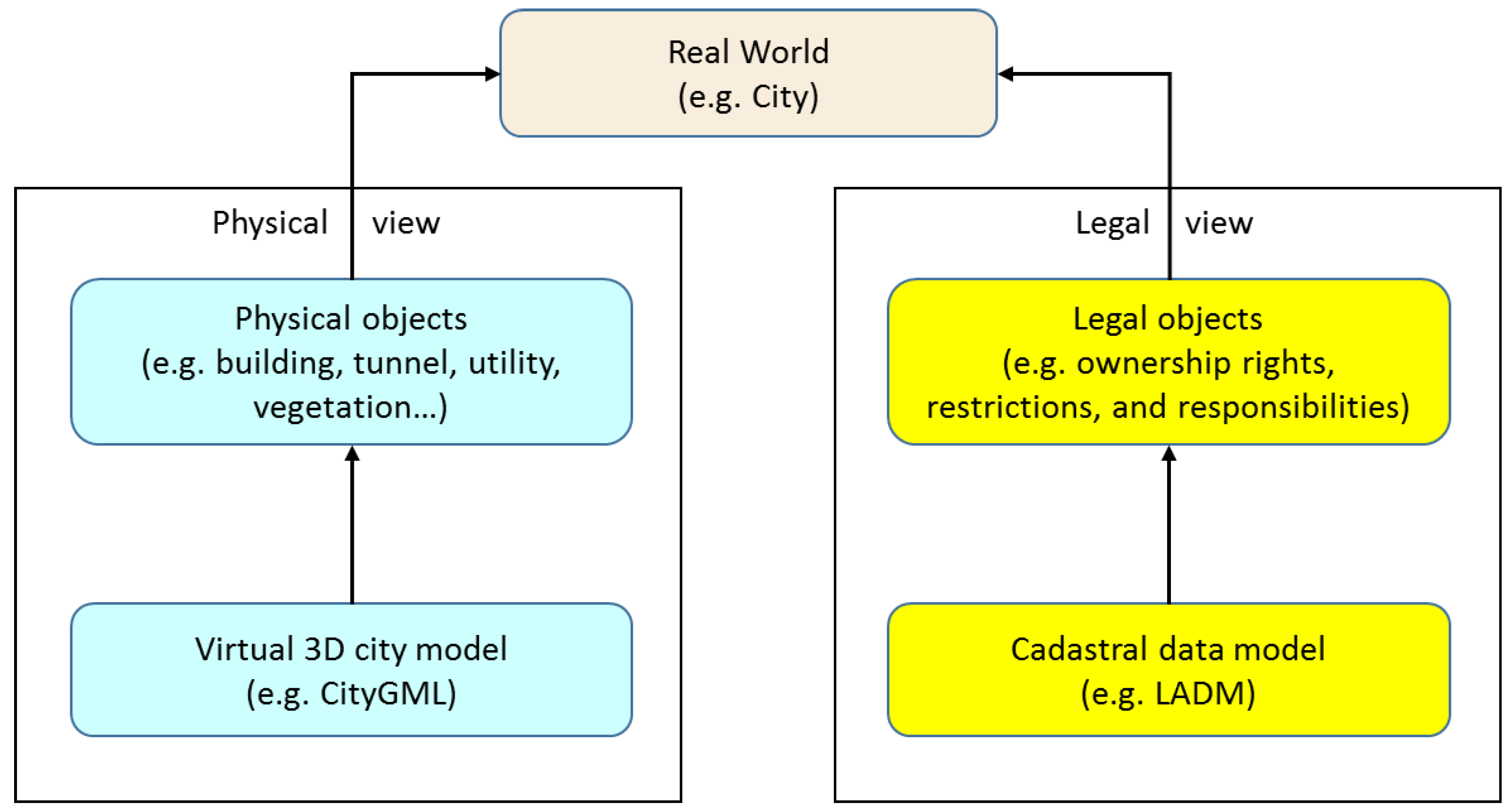
The need for more “space” resulting from population growth, urbanisation, and industrialisation has increased the pressure on land-use planning and development. As a result, space above and below ground level is increasingly used. Examples include underground developments, infrastructure facilities, high-rise buildings, and apartments. These three-dimensional (3D) developments not only increase the complexity of the urban environment (physical dimension), but also affect the land and property ownership interests attached to the underlying land (legal dimension).
Virtual 3D city models, such as CityGML, maintain and visualise 3D urban features (3D physical objects) including buildings, ground surface, streets, and vegetation [
1]; they do not focus on modelling legal objects. Cadastral data models such as Land Administration Domain Model (LADM) [
2] and ePlan [
3], on the other hand, manage and maintain the 3D land and property ownership interests, including 3D ownership rights, restrictions, and responsibilities (3D RRRs); they only represent legal objects and do not integrate their physical counterparts.
Figure 1 illustrates that cadastral data models defining legal objects of an urban environment, while virtual 3D city models outline its physical objects.
Figure 1.
Legal and physical dimensions of an urban environment.
Figure 1.
Legal and physical dimensions of an urban environment.
Since ownership boundaries (legal objects) are represented by a building’s physical structures such as walls, floors, and ceilings; cadastral data models or virtual 3D city models should maintain and integrate both legal and physical objects of urban features [
4]. This integration will maximise the usability of 3D cadastres for additional applications such as property management and city space management.
Integration of legal and physical objects in data models started almost after introduction of CityGML and Building Information model (BIM); however, few researches have been undertaken to investigate extending of cadastral data models to support this integration [
4]. The motivation why this integration starts from extending cadastral data models is first existing of strong demand from land authorities to extend their cadastral data models to support 3D cadastre and second availability of legal (cadastral) sources such as subdivision plans, titles, and deeds comparing to sources of physical information such BIM and CityGML.
1.3. Problem Description
Since ownership boundaries are defined based on the actual structures of a development (e.g., building) in cadastres, the location of boundaries must be clear. Therefore, visualising ownership boundaries alone without integrating with their physical counterparts still will not solve existing ambiguities that affect interpretation of the relationship between the rights and building interests, and will not reduce boundary confusion among owners and owner corporations. Integration of physical and legal objects, by contrast, will clearly represent the ownership rights and restrictions [
4].
Virtual 3D city models, such as CityGML, do not support objects to represent detailed information required to represent legal ownership boundaries and their physical structure counterparts [
6]. Cadastral data models such as LADM also do not maintain and represent physical counterparts of legal objects [
4].
1.4. Methodology
So far all challenges to integrate cadastral legal objects with their physical counterparts have been focused on extending virtual 3D city models to support cadastral objects. In this paper, however, the core cadastral data model is extended to support the corresponding physical objects.
This paper proposes a 3D cadastral data model (3DCDM) as a solution capable of supporting 3D data, integrating 3D physical objects with their corresponding 3D legal objects, and featuring semantically-enriched objects. The data model is developed based on the ISO standards and UML modelling language is used to specify the data model. The 3DCDM model represents 3D legal objects and connects legal and physical objects together. In this regard, the 3DCDM model is equipped with the concepts of the Legal Property Object (LPO) and the Physical Property Object (PPO). The first facilitates modelling of all existing interests (RRR) as legal objects. The second considers all 3D urban features such as buildings, tunnels, and utilities as physical objects. 3D geometric primitives of GML (Geographic Markup Language) such as Solid and MultiSurface are used to define the Legal and Physical Property Objects. The 3DCDM model supports semantics that define every aspect of legal and physical objects and, therefore, it facilitates their integration. In the 3DCDM’s UML diagrams, physical hierarchy is represented in light blue and legal hierarchy is represented in yellow to be easily distinguishable. Root classes are in light brown, Geometry classes are in green, and Address in purple. The 3DCDM’s class names are written in Italic format and its abstract classes are hyphened such as “_AbstractClass”.
1.5. Scope and Delimitation
Since the main contribution of this paper is to represent the
3DCDM model in detail, which integrates legal and physical objects, assessment of virtual 3D city models and cadastral data models in terms of supporting integration of legal and physical objects is beyond the scope of this paper, which has been investigated previously by El-Mekawy and Östman [
6] and Aien
et al. [
4]. Attributes of the
3DCDM’s classes are not also described in this paper because of space limitations.
The remainder of the paper presents the model in detail.
Section 2 describes the core component of the 3DCDM.
Section 3 illustrates all classes, associations, and attributes of the 3DCDM. The 3DCDM is evaluated by the project’s stakeholders in
Section 4. A brief discussion on the processing of changes in the data model is described in
Section 5. Research conclusions are presented in
Section 6.
2. Conceptual Model of the 3DCDM
The methodology to develop the conceptual data model of the 3DCDM is to develop the conceptual model from the core cadastral data model step by step. In the first step, the conceptual model of the core cadastral data model is represented. Then, this data model is modified to support the concept of the Legal Property Object. The logical model of the Legal Property Object model is created and its components are demonstrated. The Legal Property Object model forms the legal hierarchy of the 3DCDM model. The Physical hierarchy of the 3DCDM model that supports the physical counterparts of the legal objects (Legal Property Objects) maintains related objects such as building, tunnel, utility, and terrain model. Both hierarchies are described in the following sections.
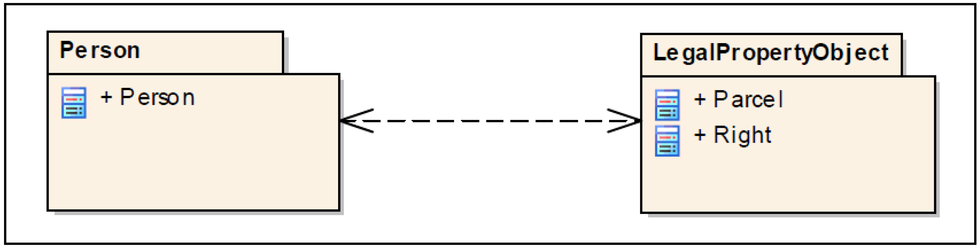
2.1. Conceptual Model of the Core Cadastral Data Model
Cadastres are dealing with entities consisting of interests in land that have three main components:
Parcel,
Right, and
Person [
17,
18]. The spatial unit of a legal object (
Right) are surveyed and demarcated by geometrical objects, while their legal descriptions (legal documents and interest holder information) are kept in the land registry (
Figure 2).
Figure 2.
Main components of current cadastral data models.
Figure 2.
Main components of current cadastral data models.
The laws define the outlines of the legal objects. The legal objects normally are described by boundaries that demarcate where a right or a restriction ends and where the next begins and the contents of that right [
19].
The UML diagram in
Figure 3 represents the core components of most current cadastral systems [
2,
3,
20,
21,
22]. In this model,
Parcel and
Right are linked together by unique identifiers (the parcel identifier). Parcel identifier is employed for organising land information.
Since cadastres are now under pressure from various land-related commodities and stratified, spatial unit (parcel)-based indexing of interests in land cannot accommodate interests that are not necessarily equivalent to the extent of spatial units or land parcels [
23]. Legal Property Object model restructures the concept of the core cadastral data model from a land parcel-based data model to a spatially referenced data model.
Figure 3.
New cadastral data model based on the Legal Property Object concept, adopted from [
23].
Figure 3.
New cadastral data model based on the Legal Property Object concept, adopted from [
23].
2.2. Conceptual Data Model of the Legal Property Object
The Legal Property Object was proposed by Kalantari [
23] to replace the core cadastral data model by a spatially-referenced data model based on the Legal Property Object concept that uniquely combines every interest and its spatial extent. The Legal Property Object includes a particular interest with its spatial dimensions.
Although land interests (RRRs) can be maintained by different organisations and have particular characteristics that drive RRRs as a separate class in cadastral data models [
24], combining
RRRs and
SpatialUnit classes into one class, Legal Property Object class (
Figure 3), facilitates the incorporation of a wide range of
RRRs into the cadastral system. Interoperability and simplicity in data-exchange processes, particularly upgrading and updating cadastral databases using spatial referencing systems, are promoted [
25].
Once the advantages of utilising the concept of Legal Property Object have been described, utilisation of this concept in the 3DCDM model can be considered. The following discussion describes how the Legal Property Object model is used in the 3DCDM model.
2.3. Utilisation of the Legal Property Object (LPO) Model in the 3DCDM
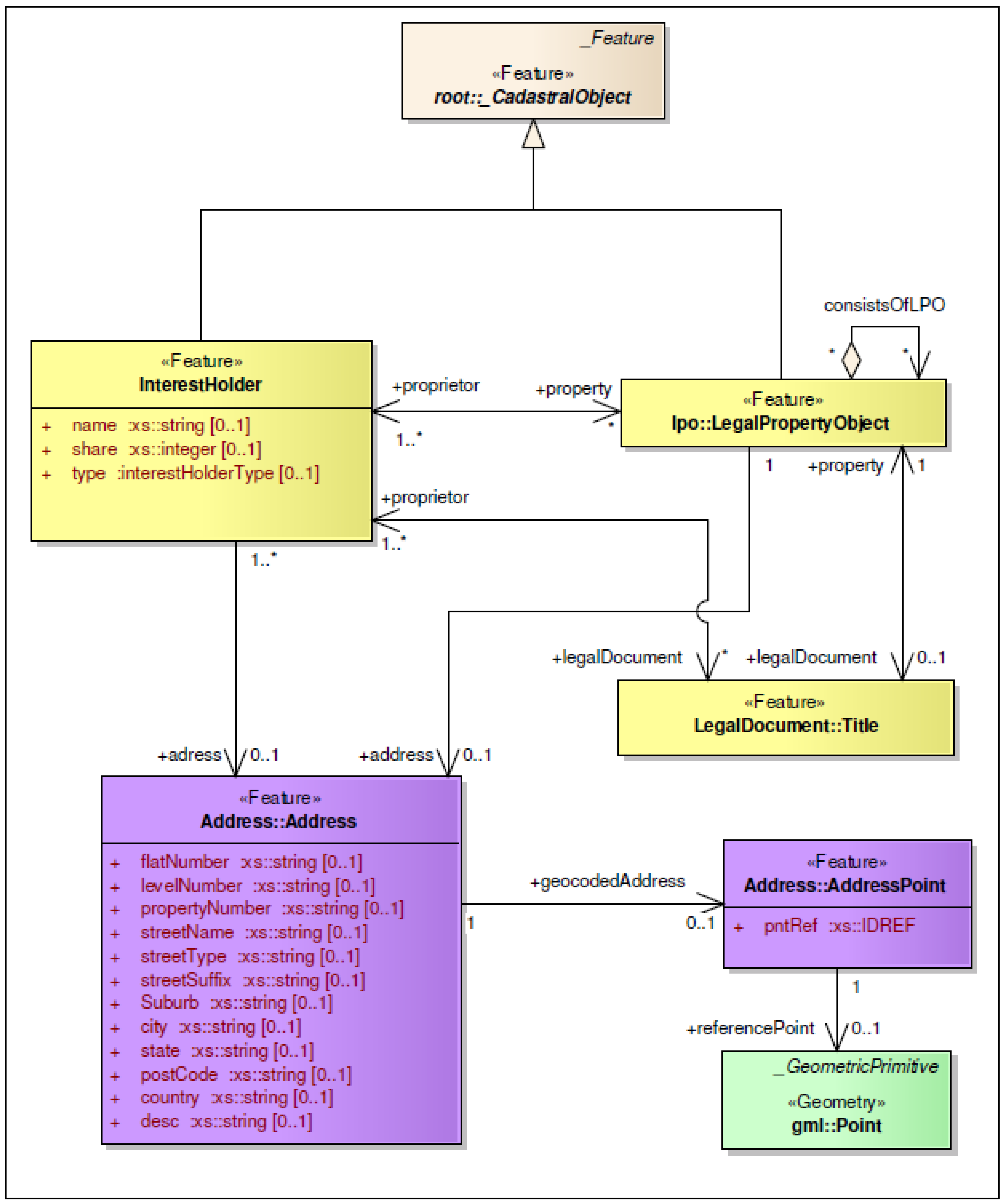
The
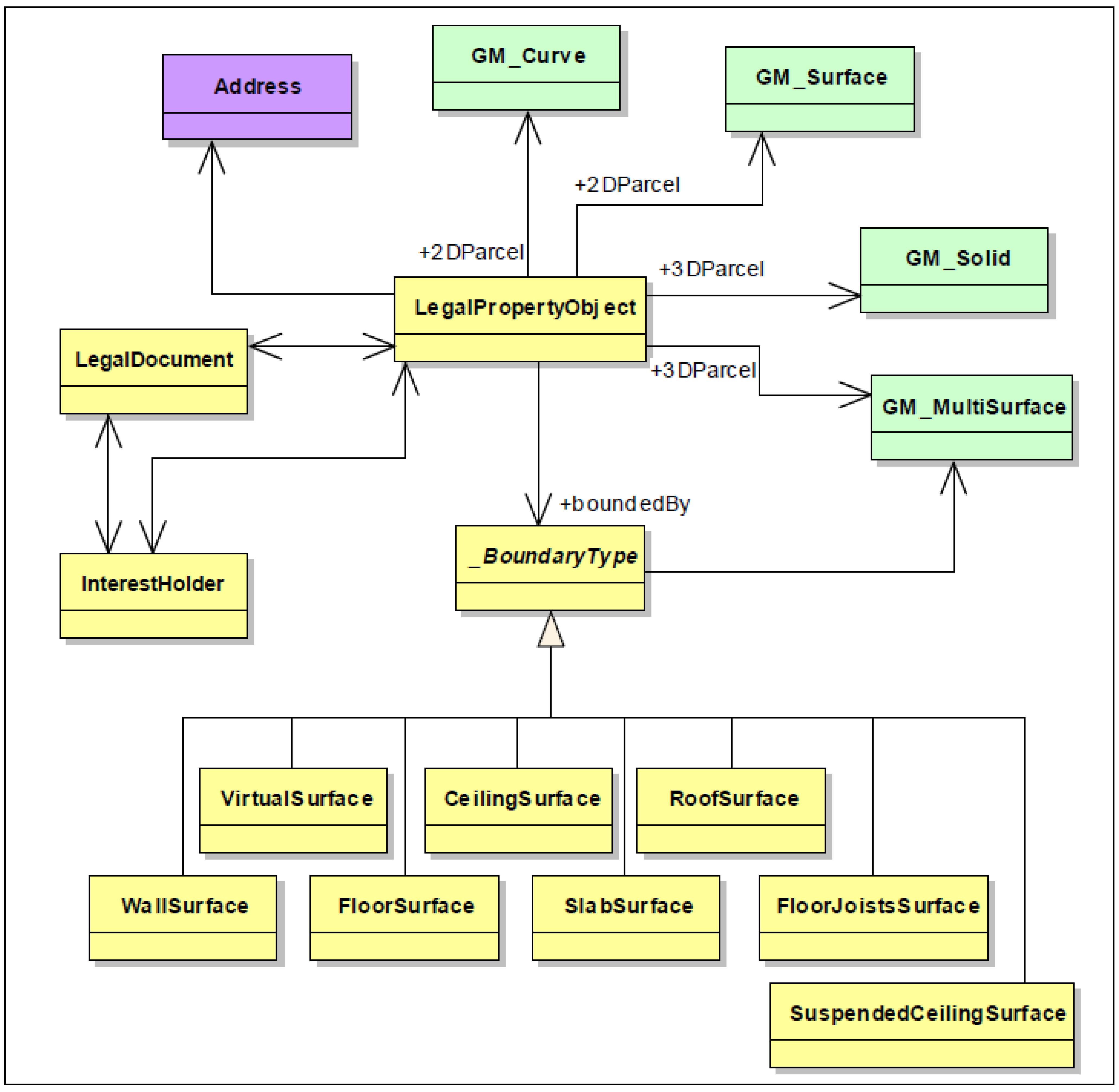
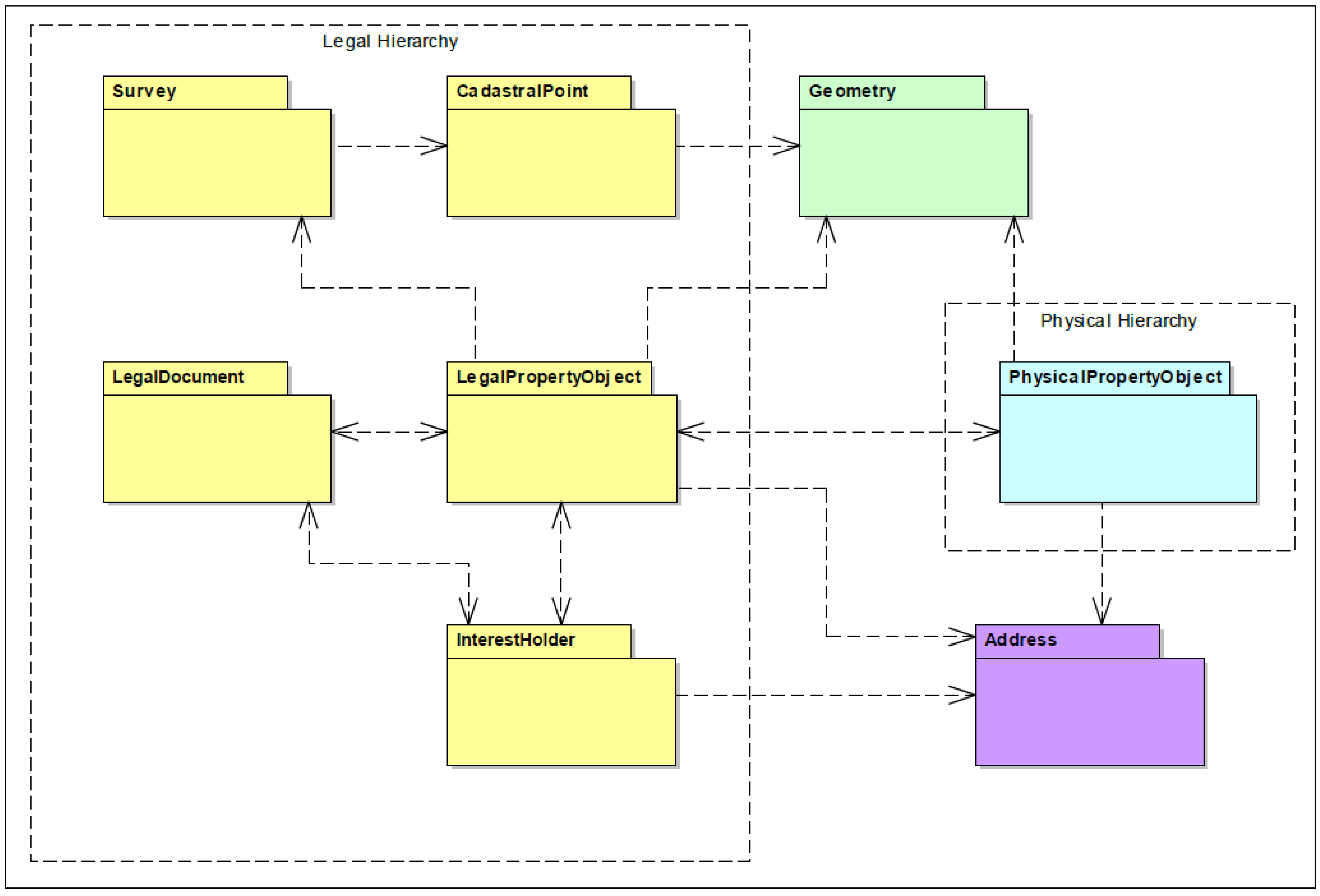
3DCDM model is developed based on the concept of the Legal Property Object. The Legal Property Object allows for the representation of spatial aspects of legal objects (2D and 3D). The UML diagram of Legal Property Object model is depicted in
Figure 4. In this model, the
LegalPropertyObject represents all land interests (rights, restrictions, and responsibilities). It is created using its associated features such as
LegalDocument,
InterestHolder,
Geometry and
Address.
Figure 4.
LegalPropertyObject’s package view, adopted from [
25].
Figure 4.
LegalPropertyObject’s package view, adopted from [
25].
Figure 5.
Geometric representation of the LegalPropertyObject.
Figure 5.
Geometric representation of the LegalPropertyObject.
The LegalDocument package contains authoritative and registered documents such as titles, deeds, or agreements. It defines rights or ownership of property attached to the Legal Property Object. The InterestHolder package maintains information about the interest holder of the Legal Property Object and the Address package maintains the physical address of the Legal Property Object and living address of the interest holder. The Geometry package includes zero, one, two, and three-dimensional geometric primitives to represent spatial extent of the Legal Property Object. The Legal Property Object model is the core component of the 3DCDM model.
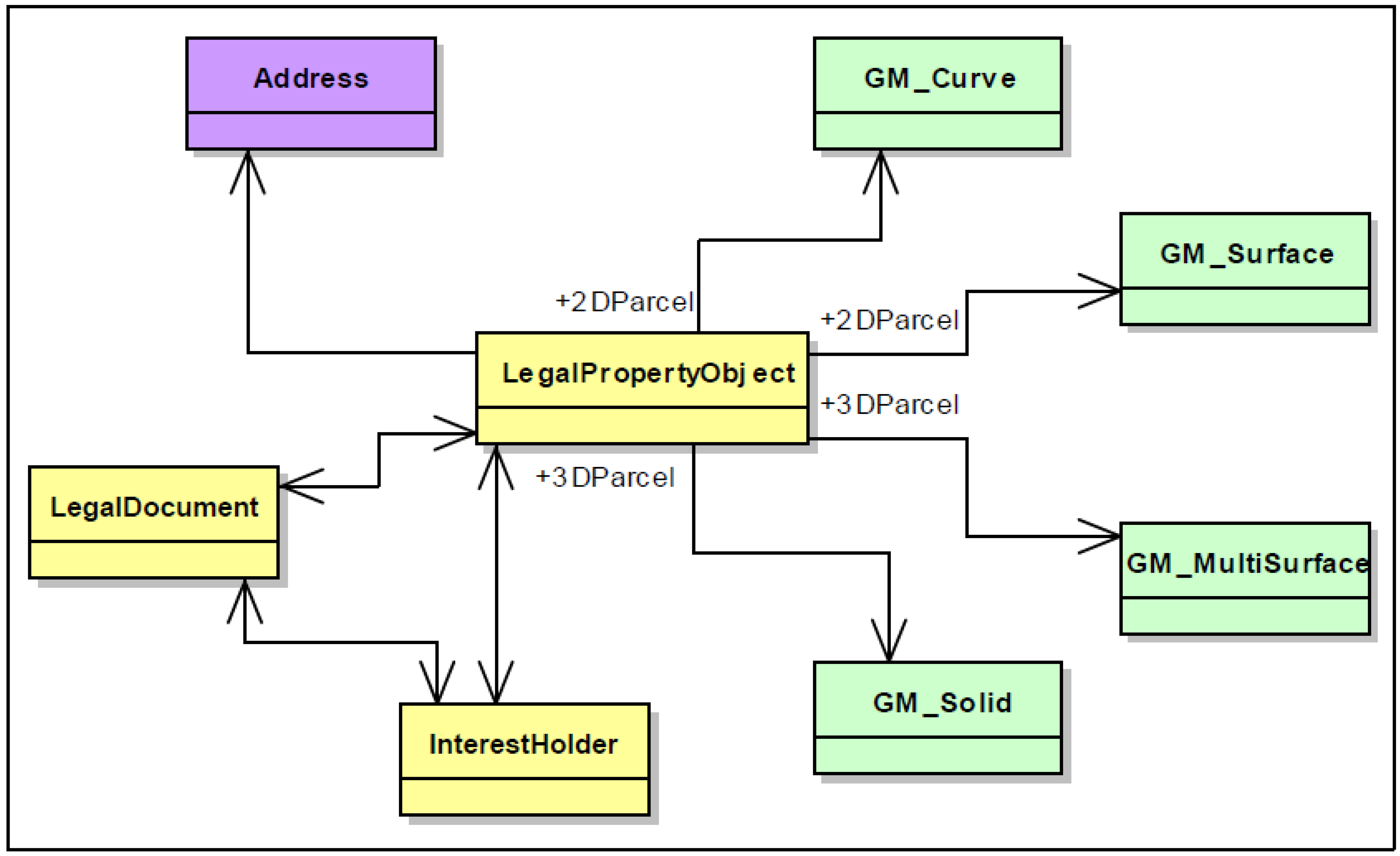
2.4. Geometry of LegalPropertyObject Class in the 3DCDM
In The
3DCDM model,
LegalPropertyObject class plays the role of a 3D parcel. It contains required legal object information and its spatial properties are represented by 2D or 3D geometrical primitives [
26].
The geometric representation of a
LegalPropertyObject class is shown in
Figure 5. If the
LegalPropertyObject is a 2D object such as a land parcel, it can be represented by 1D geometric primitives, such as
GM_MultiCurve or with
GM_MultiSurface, and if it is a 3D object, such as a volumetric space (3D parcel), a 3D geometric primitives, such as
GM_Solid, is used.
Few cadastral data models support 3D parcels to model 3D RRRs. However, they do not use solid geometry (Solid) to represent 3D parcels. Solid geometry facilitates 3D representation, volumetric calculation, and 3D spatial analysis. The
3DCDM model supports solid representation [
4].
2.5. Integration of Legal and Physical Objects in the 3DCDM Model
There is a need for integration between legal objects and their physical counterparts for 3D cadastral applications [
4]. Boundaries of 3D parcels (ownership spaces) are defined based on the actual structures of a building to determine the legal volume. In the paper based plans of subdivision, the boundaries of ownership are only representative. For building subdivisions, from legal perspective, the actual structure of the building defines the ownership spaces. In other words, the legal definition is equal to the physical definition. In the digital world it is, therefore, necessary to have a physical definition of the buildings in the cadastres. Therefore, visualising 3D parcels only in 3D cadastres does not clearly represent the actual information of ownership rights, restriction, and responsibilities. Using 3D parcels alone without integrating with their physical counterparts, such as building structures, still will not solve existing ambiguities that affect interpretation of the relationship between the rights and building interests, and will not reduce boundary confusion among owners and owner corporations. Integration of physical and legal objects, by contrast, will clearly represent the legal structure of a building.
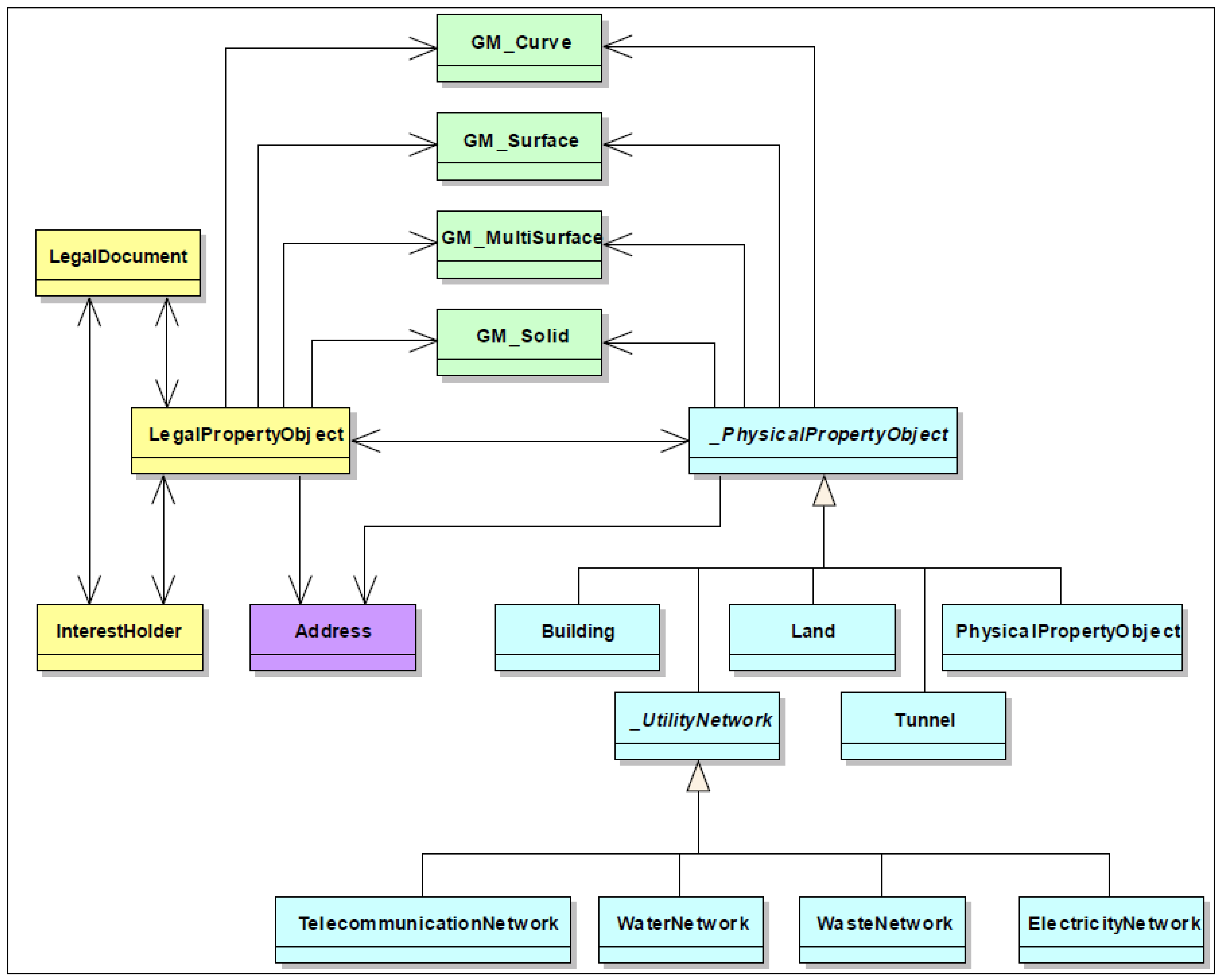
Figure 6 illustrates how physical information (_PhysicalPropertyObject) is associated with the LegalPropertyObject with the purpose of having more realistic 3D objects in 3D cadastres.
The LegalPropertyObject represents any type of legal object. Each LegalPropertyObject has one or more owners (InterestHolder). Each LegalPropertyObject is associated with zero or more abstract class _PhysicalPropertyObject, which has four subclass specialisations: Building, Land, Tunnel, _UtilityNetwork, and PhysicalPropertyObject (any type of Physical Property Object such as a mine, road, or sea). The association between LegalPropertyObject and _PhysicalPropertyObject is bi-directional, which means that it is possible to navigate from each hierarchy (legal or Physical) to find the corresponding object.
Abstract class _PhysicalPropertyObject is a superclass in the physical hierarchy of the 3DCDM model, while class LegalPropertyObject is the core class in the legal hierarchy.
Physical Property Objects are important for cadastral applications. Having separate class PhysicalPropertyObject facilitates a selection of an appropriate PhysicalPropertyObject for any particular application. In terms of modelling a building, only Building subclass is used. Also class Building can be aggregated with class Tunnel and _UtilityNetwork’s subclasses to provide more comprehensive model. Each subclass has its own subclasses and different types of interrelationships between feature classes like aggregations, generalisations, and associations.
In the 3DCDM model, all physical and legal objects have a unique objectID in the entire model. In this method, in the legal hierarchy, a LegalPropertyObject is generated and an objectID is assigned to that. Also, in the physical hierarchy, a PhysicalPropertyObject such as a building, a unit, a wall, or a water network is created and its corresponding legal object is referenced by attributes (objectID). If the PhysicalPropertyObject and its counterpart have a similar geometry (for example, when a wall is an interior boundary of ownership right), then the geometry is only created for the PhysicalPropertyObject and the geometry of the corresponding LegalPropertyObject will be represented by referencing to its physical object.
Figure 6.
Conceptual model of integrating the legal and physical objects in the 3DCDM model.
Figure 6.
Conceptual model of integrating the legal and physical objects in the 3DCDM model.
Figure 7.
Spatially and semantically coherent conceptual model of the LegalPropertyObject.
Figure 7.
Spatially and semantically coherent conceptual model of the LegalPropertyObject.
2.6. Utilisation of Semantics in the 3DCDM Model
There is a need to utilise semantics in cadastral models. Therefore, these models can be used for visualisation, thematic queries, and spatial analysis purposes.
The 3DCDM model integrates the legal and physical objects with the semantics associated with the data. There is a coherent modelling of semantics and geometrical properties in the 3DCDM model. Furthermore, attributes and associations between features support semantics.
Semantically, legal objects are represented by the
LegalPropertyObjects.
LegalPropertyObject’s attributes identify the type of the legal object and further support semantics. For example, the
LegalPropertyObject object can be an ownership, common property, easement, covenant, or license. Physical objects also are represented by features such as
Building,
Land,
Tunnel, and
_UtilityNetwork (
Figure 6).
Spatially, geometrical objects represent the location, boundary and extent of the legal and physical objects, while each geometrical object is instantiated by semantics in the
3DCDM model.
Figure 7 represents how geometrical objects (green objects) are linked to their corresponding semantics.
In this model, solid geometry (GM_Solid) is used to spatially create a 3D LegalPropertyObject, such as a volumetric ownership space of a unit in a building. In addition, BoundayType class specialisations such as VirtualSurface, WallSurface, FloorSurface, and CeilingSurface are used to semantically enrich the created LegalPropertyObject. This concept applies to the physical objects as well. Therefore, all legal and physical objects in the 3DCDM model are enriched with semantics.
2.7. Components of the 3DCDM Model
Surveying information including observations and cadastral control points, which are important elements in cadastral plans, are considered as a separate module in the
3DCDM model.
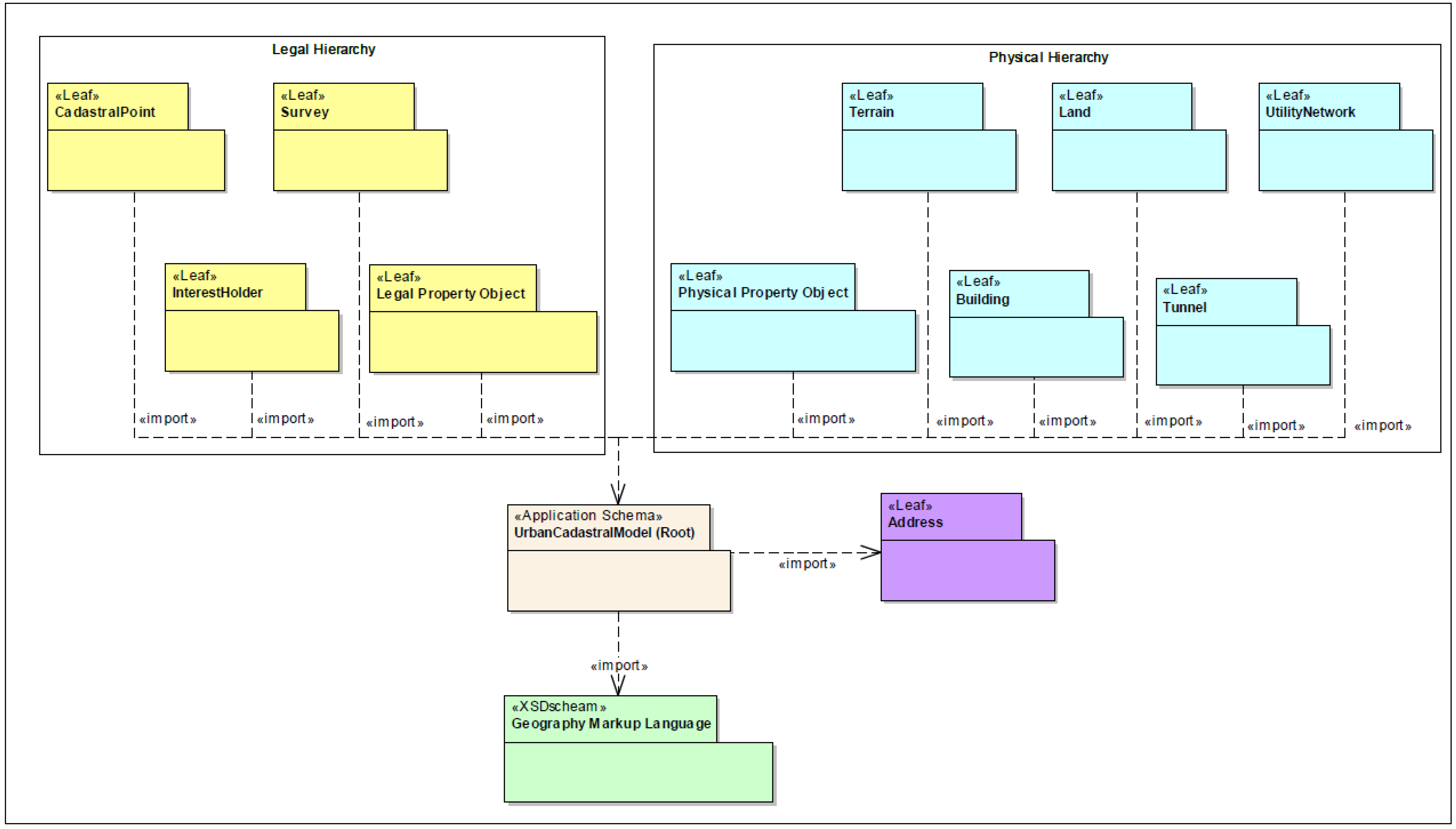
Figure 8 represents the conceptual model of the
3DCDM, which includes the main features of the 3D cadastre. As previously discussed, the
3DCDM model has two hierarchies, legal and physical.
Survey and
CadastralPoint are included in the legal hierarchy. They cover the required surveying information of the Legal Property Object.
Figure 8.
Conceptual Model of the 3DCDM.
Figure 8.
Conceptual Model of the 3DCDM.
3. Logical Model of the 3DCDM
In this section, the logical data model of the
3DCDM model is presented based on the conceptual model of the
3DCDM model. The
3DCDM model is implemented as an application schema of the Geography Markup Language 3 (GML3), version GML3.2.1, the extendable international standard for spatial data exchange and encoding issued by the Open Geospatial Consortium (OGC) and the ISO TC211. The 3DCDM model inherits GML3’s specifications. GML3.2.1 supports most of the
3DCDM’s general and spatial requirements. GML 3.2.1 maintains wide variety of spatial reference systems; it has a rich geometric model and provides essential attributes to develop the
3DCDM model (
Figure 9). Different components and classes of the
3DCDM model are represented in this section in detail.
3.1. 3DCDM Hierarchies and Components
The 3DCDM model is composed of two hierarchies: legal and physical. However, they are connected to each other through the associations between their subclasses. The 3DCDM’s users can navigate through each hierarchy independently and also between hierarchies.
Each hierarchy consists of different components and they are all connected to the core component of the 3DCDM model, which is called the root model. The root model contains the basic features on the 3DCDM model. The root model must be implemented in any conformant system.
The legal hierarchy of the
3DCDM model comprises of the following components:
LegalPropertyObject,
Survey,
CadastralPoint, and
InterestHolder. The physical hierarchy has the following components:
PhysicalPropertyObject,
Building,
Land,
Tunnel,
UtilityNetwork, and
Terrain. The
3DCDM model supports the combination of different legal and physical components to provide more comprehensive cadastral model (
Figure 9).
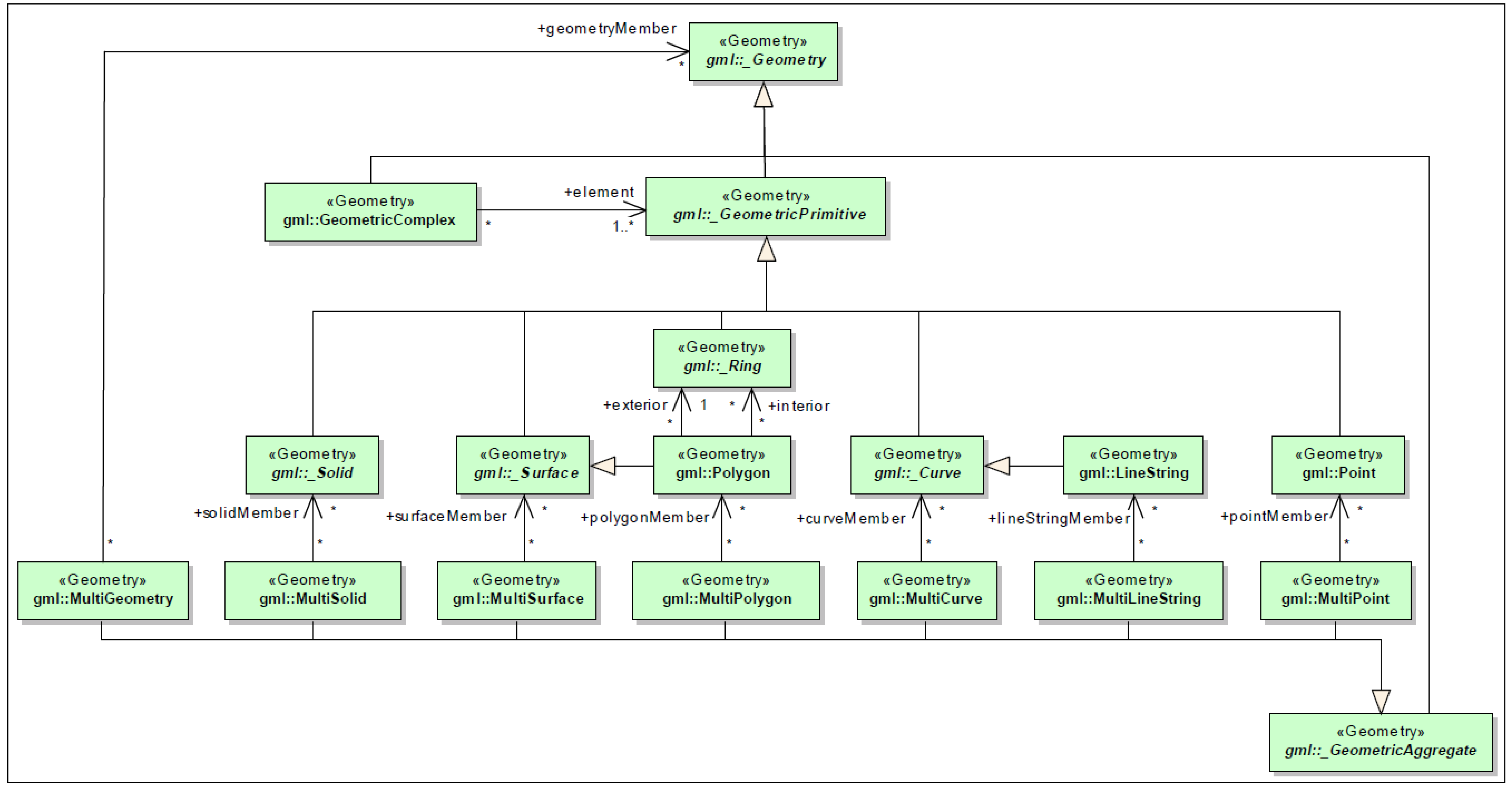
The geometry model of the
3DCDM is based on the geometry model of Geographic Markup Language (GML3.2.1). GML follows the specification of standard ISO 19107 “Spatial schema” [
27]. GML represents 3D geometry according to the well-known Boundary Representation [
28]. There is a geometrical primitive for each dimension:
Point for a zero-dimensional object,
Curve for a one-dimensional,
Surface for two-dimensional objects, and
Solid for three-dimensional objects. A solid is bounded by surfaces and a surface by curves [
29].
Combined geometries can be aggregates, complexes or composites of primitives. For an aggregate, the spatial relationship between primitives is not defined. They may be disjoint, touching, or overlapping. GML provides a special aggregate for each dimension, a
MultiPoint, a
MultiCurve, a
MultiSurface, and a
MultiSolid. On the contrary, a complex is topologically structured. Complex elements must be disjointed and must not overlap. They must be topologically connected along their boundaries. A composite is a special complex that can only contain elements of the same dimension. A composite can be a
CompositeCurve,
CompositeSurface, and a
CompositeSolid [
27].
The Geometry model contains the various classes for coordinate geometry [
27]. All of these classes, through the root class, inherit an optional association to a coordinate reference system. The geometry package has several internal packages that separate primitive geometric objects, aggregates, and complexes, which have a more elaborate internal structure than simple aggregates [
29].
Figure 10 show one part of the
3DCDM geometry model.
Figure 9.
Separate models and hierarchies of the 3DCDM model.
Figure 9.
Separate models and hierarchies of the 3DCDM model.
Figure 10.
A part of 3DCDM Geometry Model—(profile of GML3.2.1).
Figure 10.
A part of 3DCDM Geometry Model—(profile of GML3.2.1).
3.2. 3DCDM Root Model
The
3DCDM Root model comprises of core features and components of the
3DCDM model. All other models are connected to the root. This component of the
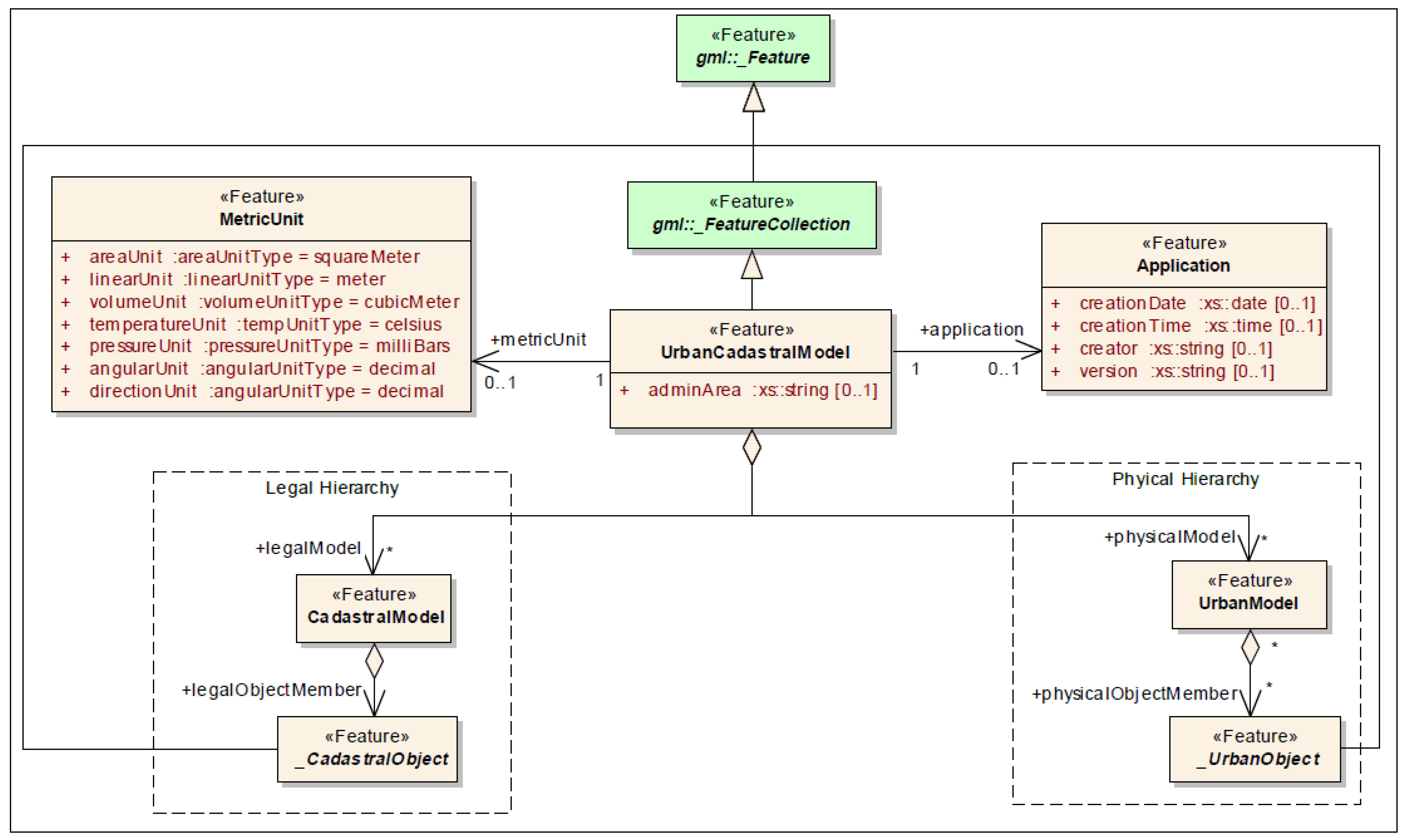
3DCDM model must be realised in the implementation phase of the data model. The root model consists of two legal and physical hierarchies and it provides the opportunity for the user to choose one of or both hierarchies. The UML diagram in
Figure 11 illustrates
3DCDM’s root model.
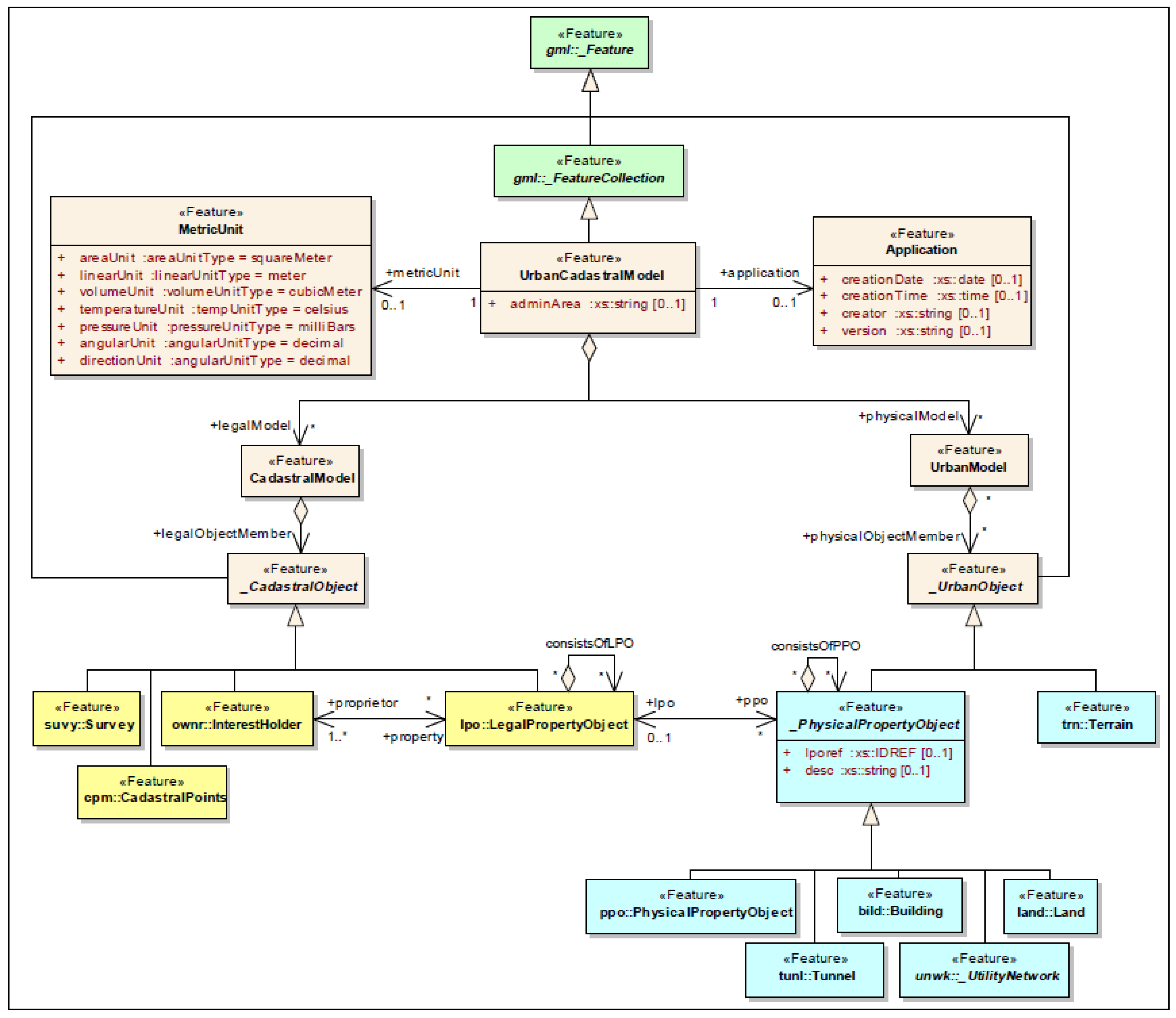
The 3DCDM’s root model consists of gml:_Feature, gml;_FeatureCollection, UrbanCadastralModel, Application, MericUnit, CadastralModel, _CadastralObject, UrbanModel, and _UrbanObject.
gml:_Feature
This abstract element serves as the head of a substitution group, which may contain any elements. Abstract
gml:_Feature may be thought of as “anything that is a GML feature” [
29].
gml:_FeatureCollection
Abstract class gml:_FeatureCollection is a subclass of the GML class gml:_Feature and is a collection of properties that apply to the gml:_FeatureCollection and an optional list of Spatial Reference System Definitions.
UrbanCadastralModel
UrbanCadastralModel is the base class of all components in the
3DCDM model. Its
adminArea attribute enables specification of the area where the cadastral model is created.
UrbanCadastralModel is a subclass of the GML class
gml:_Feature.
UrbanCadastralModel consists of zero or more CadastralModel and UrbanModel (
Figure 11). Therefore, it inherits the metadata property such as Coordinate Reference System (CRS) and general properties such as name from its superclass.
Application
This class provides further metadata about the application that created the model. MetricUnit.
This class provides further metadata about the measurement units.
CadastralModel
This class is the first class of the 3DCDM’s legal hierarchy. It forms the cadastral model and contains the legal objects.
_CadastralObject
Abstract class _
CadastralObject is the base class of all legal classes in the
3DCDM. It is a subclass of
gml:_Feature.
_CadastralObject subclasses are
LegalPropertyObject,
InterestHolder,
Survey, and
CadastralPoints (
Figure 12).
Figure 11.
UML diagram of the 3DCDM Root model.
Figure 11.
UML diagram of the 3DCDM Root model.
Figure 12.
The UML diagram of 3DCDM Root model and subclasses of the legal and physical models.
Figure 12.
The UML diagram of 3DCDM Root model and subclasses of the legal and physical models.
UrbanModel
This class is the first class of the 3DCDM’s physical hierarchy. It forms the urban model and contains physical objects.
_UrbanObject
Abstract class
_UrbanObject is the base class of all physical classes in the
3DCDM. It is a subclass of gml:_Feature.
_UrbanObject subclasses are
_PhysicalPropertyObject,
Terrain,
Building,
Land,
Tunnel,
_UtilityNetwork, and _
PhysicalPropertyObject (
Figure 12).
3.3. 3DCDM LegalPropertyObject Model
Every legal object is represented as a
LegalPropertyObject in the
3DCDM model.
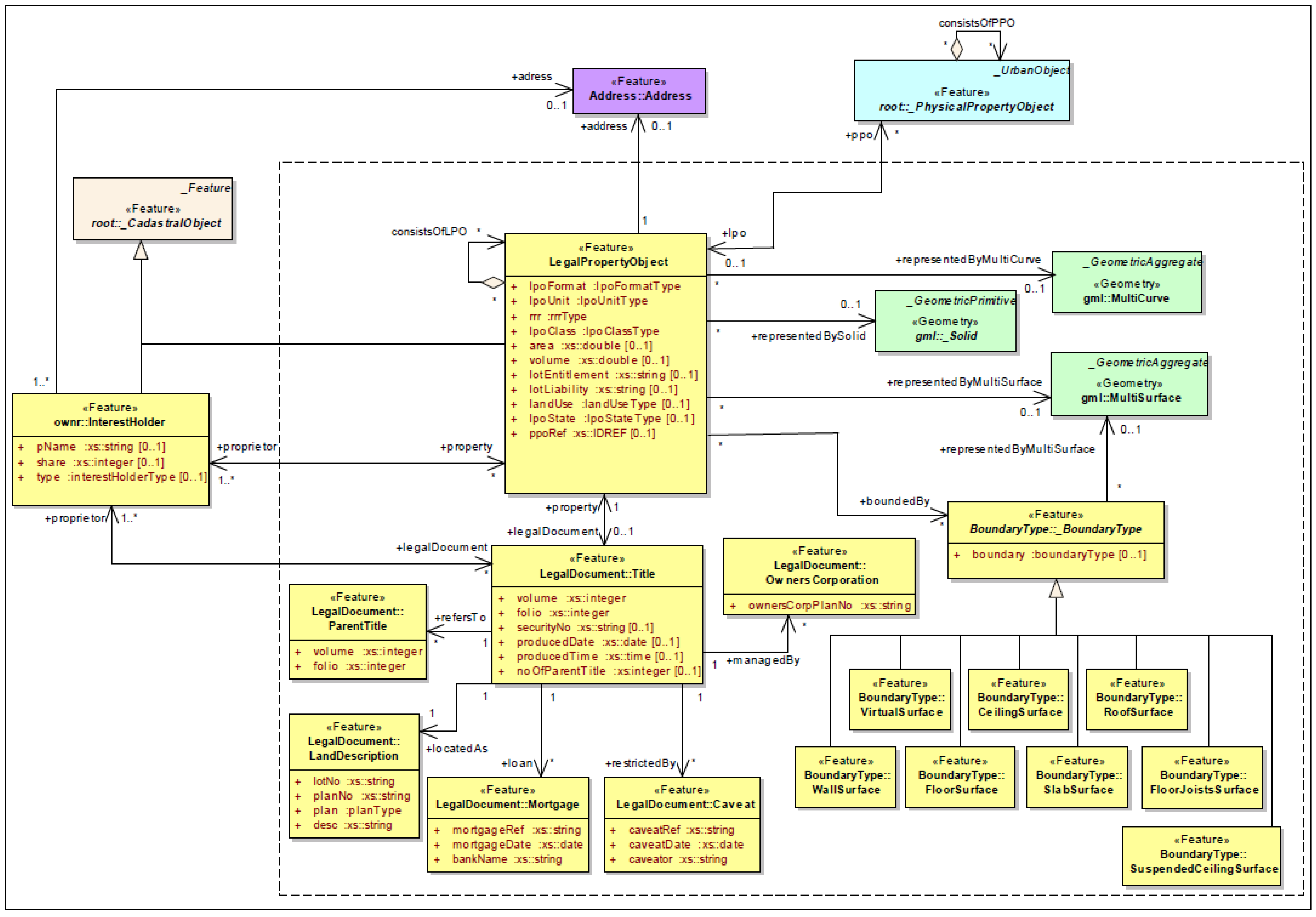
Figure 13 represents the attributes and associated classes of the class
LegalPropertyObject. Each
LegalPropertyObject class is associated with zero or more
_PhysicalPropertyObjects, such as
Building,
Tunnel, _
UtilityNetwork, and
Land. It has one or more
InterestHolders. Each
LegalPropertyObject acquires its legal information through its associated
LegalDocument.
Ownership space is more of a conceptual concept. Physical structures such as fences, hedges, or walls are used to demarcate and represent the ownership boundaries. However, the legal spaces (boundaries) are not always equal to their corresponding physical spaces (physical boundaries). For example, legal boundaries (ownership volumes) are usually bigger than the physical boundaries (building) in villa units. Furthermore, in some cases such as airspace, the legal space cannot be defined by physical boundaries. For these reasons, the creation of Legal Property Object in 3D cadastres is needed. The
3DCDM supports creation of
LegalPropertyObject using GML geometry objects. If the
LegalPropertyObject is a 2D land parcel, it can be created using
gml:MultiCurve or
gml:MultiSurface. And if it is a 3D parcel, it can be created using
gml:MultiSurface or
gml:_Solid (
Figure 14).
However, if the LegalPropertyObject is equal to its physical counterpart and can be defined using physical objects; the 3DCDM provides various boundary types such as WallSurface, CeilingSurface, FloorSurface, RoofSurface, SlabSurface, SuspendedCeilingSurface, or FloorJoistSurface to semantically define the boundary of a LegalPropertyObject.
Another method to semantically define the legal boundaries in the 3DCDM is to use the LegalPropertyObject’s attribute ppoRef to reference a physical object.
LegalPropertyObject
This class represents all types of legal objects such land parcel, 3D parcel, ownership, easement, and common property. LegalPropertObject is a subclass of _CadastralObject. LegalPropertObject is associated to the class Address that identifies the physical address of the LegalPropertObject.
LegalDocument: Title
Each
LegalPropertyObject is associated with one legal document such as a title, a deed, an agreement if it has been registered. It is also possible to identify the
LegalPropertyObject through the legal documents (
Figure 13).
LegalDocument: ParentTitle
Each
Title can be associated to zero or more
ParentTitle (
Figure 13).
LegalDocument: LandDescription
LegalPropertyObject’s specification is described in class
LegalDescription (
Figure 13).
LegalDocument: Mortgage
Title can be associated to the class
Mortgage (
Figure 13).
Mortgage is registered as a restriction in the
Title.
Figure 13.
The UML diagram of 3DCDM LegalPropertyObject model.
Figure 13.
The UML diagram of 3DCDM LegalPropertyObject model.
Figure 14.
The UML diagram of 3DCDM InterestHolder model.
Figure 14.
The UML diagram of 3DCDM InterestHolder model.
LegalDocument: Caveat
Title can be associated to the class
Caveat (
Figure 13).
Caveat is registered as a restriction in the
Title.
LegalDocument: OwnersCorporation
Title can be associated to the class
OwnersCorporation (
Figure 13).
OwnersCorporation is registered to manage the property when it has common areas.
BoundaryType:_BoundaryType
Abstract class _BoundaryType contains different subclasses to semantically define the LegalPropertyObject. They are VirtualSurface, WallSurface, CeilingSurface, FloorSurface, RoofSurface, SlabSurface, SuspendedCeilingSurface, and FloorJoistsSurface (
Figure 13).
3.4. 3DCDM InterestHolder Model
This model maintains information about the land interest holder. This model has only one class, which is class InterestHolder.
InterestHolder
InterestHolder can be a person, group, or an organisation that have certain rights (RRRs) over a particular 3D space. An
InterestHolder can be associated with the classes
LegalPropertyObject and
Title.
InterestHolder is a subclass of
_CadastralObject (
Figure 14).
InterestHolder is associated to the class
Address, which identifies the living address of the interest holder.
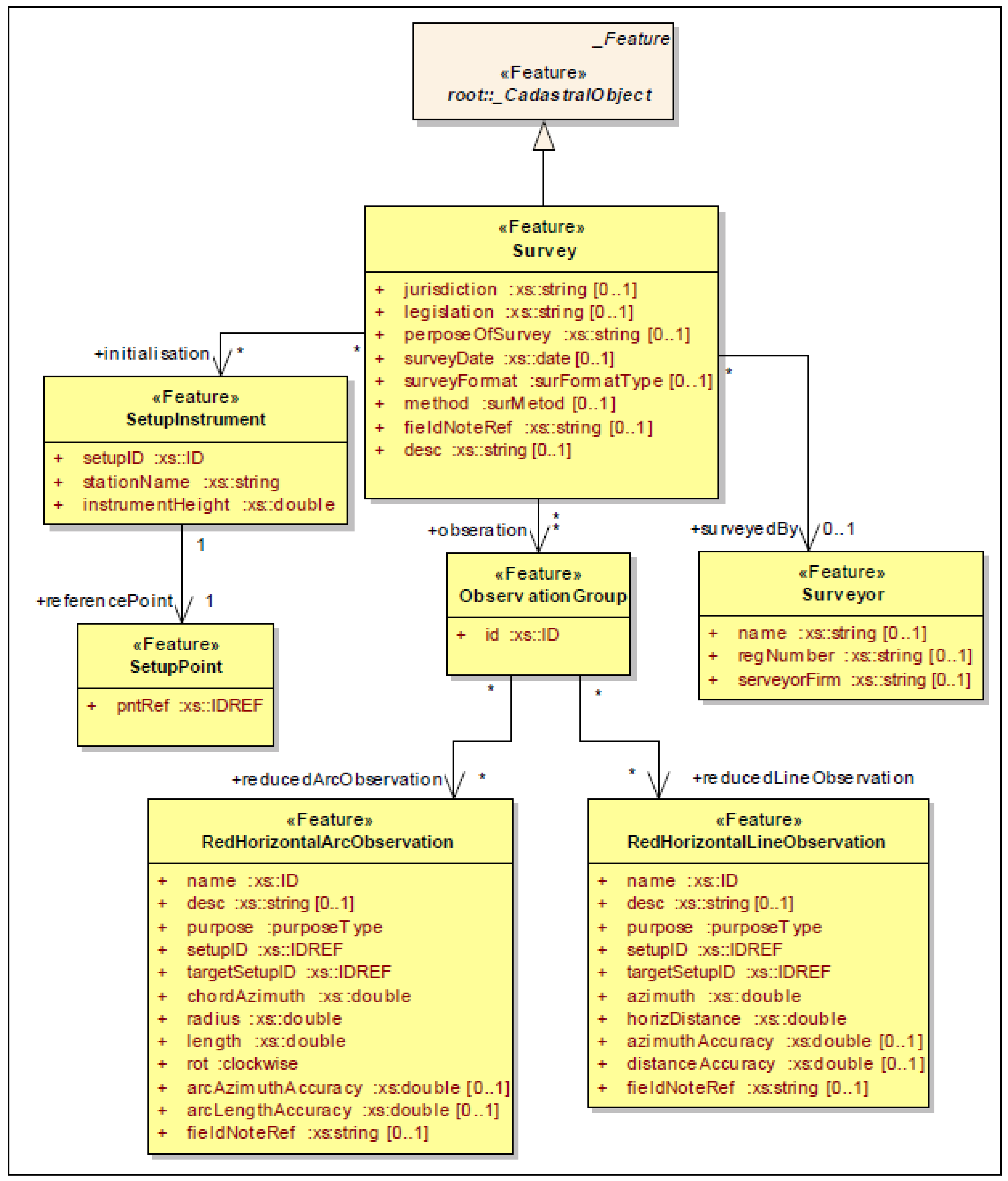
3.5. 3DCDM Survey Model
The Survey model contains seven classes that describe technical and administrative information of surveying and surveyor, which is required in cadastral applications.
Survey
The class
Survey is the main class of the model and holds general information of surveying (
Figure 15).
Survey is a subclass of
_CadastralObject.
Surveyor
The class
Surveyor maintains the details of any surveyor who participated in the survey (
Figure 15).
SetupInstrument
The class
SetupInstrument retains setting-up information of surveying instruments on surveying points (
Figure 15).
SetupPoint
The class
SetupPoint refers to the setup points of the cadastral points (
Figure 15).
ObservationGroup
Surveying observations are maintained in the class
ObservationGroup and its associated classes
RedHorizontalArcObservation and
RedHorizontalLineObservation (
Figure 15).
RedHorizontalArcObservation
The class
RedHorizontalArcObservation holds horizontally reduced observations for arcs (
Figure 15).
RedHorizontalLineObservation
The class
RedHorizontalLineObservation holds horizontally reduced observations for lines (
Figure 15).
Figure 15.
The UML diagram of 3DCDM Survey model.
Figure 15.
The UML diagram of 3DCDM Survey model.
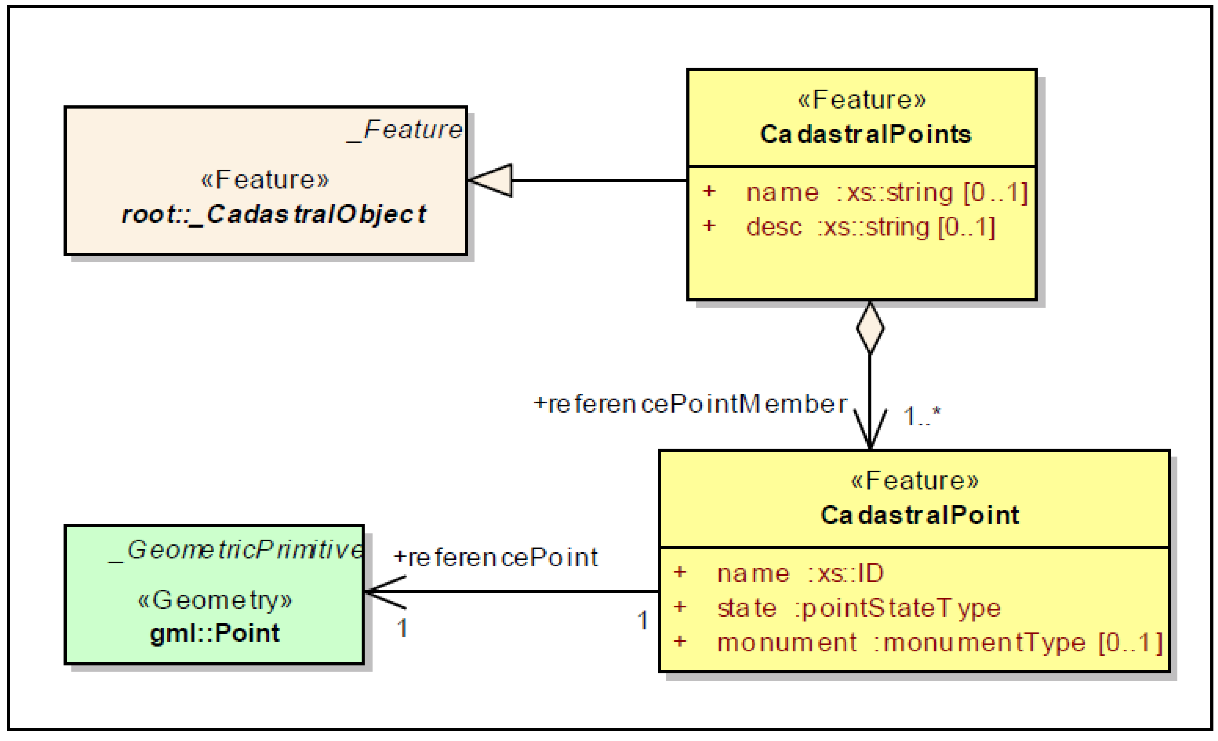
3.6. 3DCDM CadastralPoints Model
As surveying of permanent marks is very important for surveyors, the
3DCDM model keeps the elements related to the survey permanent marks as the
CadastralPoints model. Permanent marks are placed in the ground by monuments (e.g., pin, peg) during the survey process. Survey points can be 2D or 3D. The
CadastralPoints model contains two main classes that describe the information of survey points (
Figure 16).
CadastralPoints
The class
CadastralPoints is a subclass of
_CadastralObject. The class
CadastralPoints is a group of survey points (
Figure 16).
CadastralPoint
The class
CadastralPoints consists of one or more
CadastralPoint, which is created using
gml:point geometry object (
Figure 16).
Figure 16.
The UML diagram of 3DCDM CadastralPoints model.
Figure 16.
The UML diagram of 3DCDM CadastralPoints model.
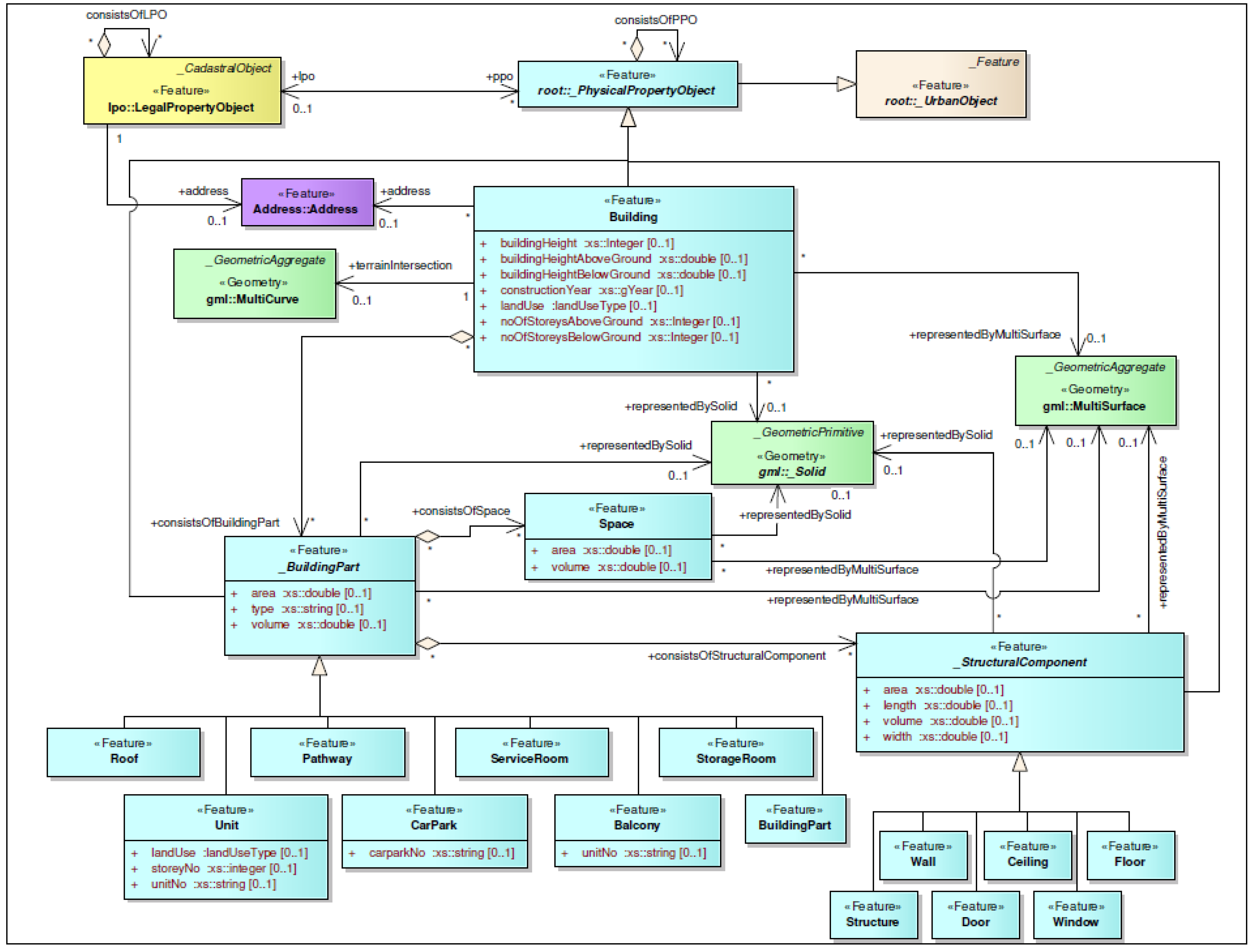
3.7. 3DCDM Building Model
The
3DCDM supports the
Building model. The
3DCDM model allows users to create the building models and then link it to its legal counterparts. The
Building model is located in the physical hierarchy of the
3DCDM model. The
Building model has an abstract superclass
_PhysicalPropertyObject that is associated with zero or one
LegalPropertyObject. The abstract class
_PhysicalPropertyObject is a subclass of
_UrbanObject. The
Building model can be created through four main subclasses. They are class
Building, abstract class
_BuildingPart, class
Space, and abstract class
_StructuralComponent (
Figure 17).
Building
The class
Building describes the physical shape (without internal components) of a building. The class
Building is a 3D object and is created using
gml:_Solid or
gml:MultiSurface geometry object. The class
Building’s set of attributes help to almost envisage the shape of the building. In the
3DCDM model, the intersection lines of a building and terrain surface is represented using
gml:MultiCurve. The class
Building is associated to the class
Address to specify the physical address of each building. A building is decomposed into different building parts (
Figure 17).
_BuildingPart
The abstract class
_BuildingPart and its specialisations such as
Unit,
CarPark,
Roof,
Pathway,
ServiceRoom,
StorageRoom,
Balcony, and
BuildingPart (any type of building part) are used to model the internal sections of a building (
Figure 17).
Space
Each building part can be created using zero or more spaces. The class
Space defines the internal volumetric space of a
_BuildingPart.
Space is a 3D object and can be represented using
gml:MultiSurface or
gml:_Solid (
Figure 17).
_StructuralComponent
Each building part can be created using zero or more
_StructuralComponent. The abstract class
_StructuralComponent defines the structures that are used to create the
_BuildingPart. Each
_StructuralComponent can be represented using
gml:MultiSurface or
gml:_Solid. The abstract class
_StructuralComponent’s semantically defines the type of building structure (
Figure 17). They are
Wall,
Ceiling,
Floor,
Door,
Window, and
Structure (any type of structure such as a pile).
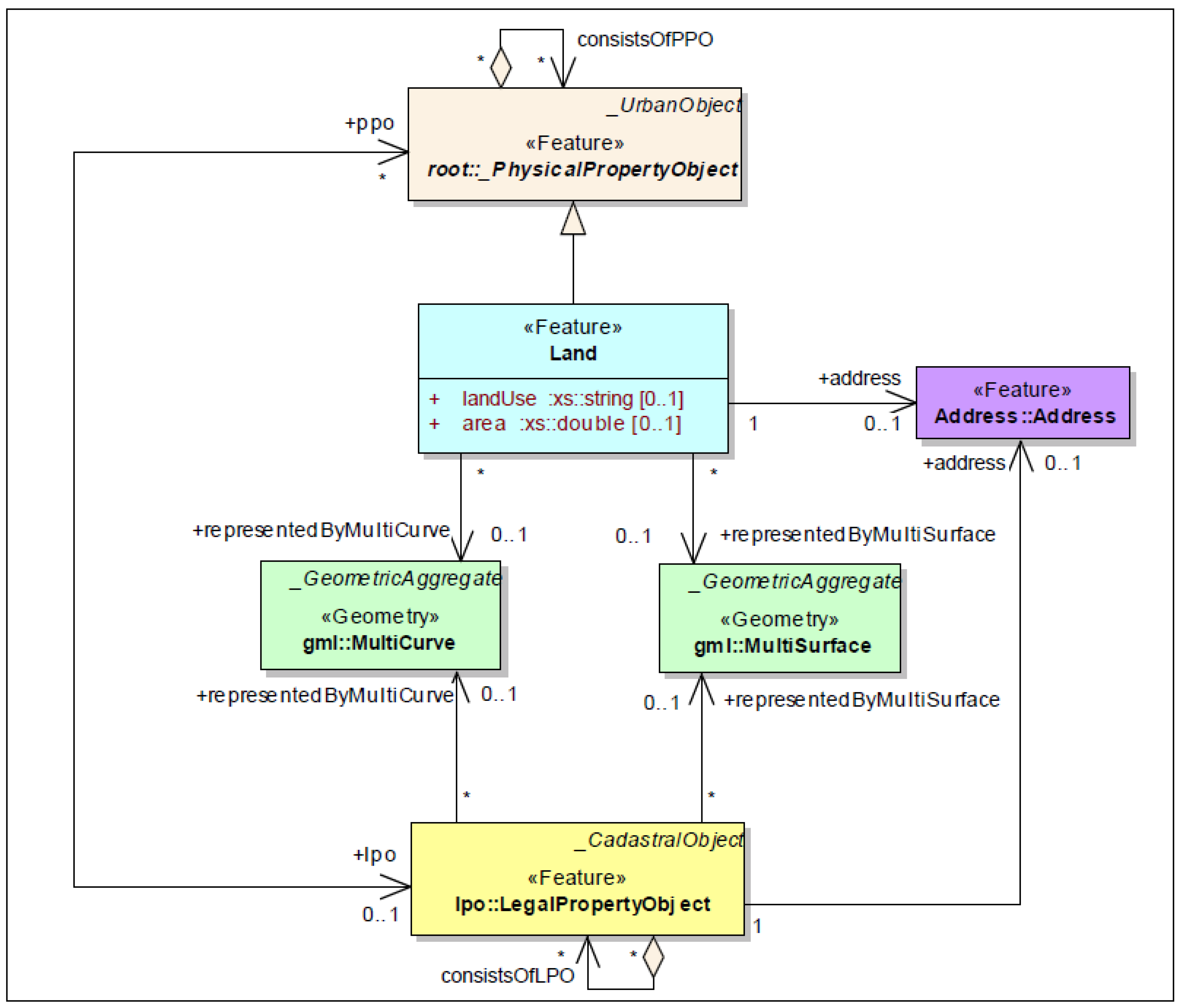
3.8. 3DCDM Land Model
Land model in the 3DCDM model is used for 2D cadastral applications. In this model, it considers a physical object that legal entities will be attached to. The Land model has an abstract superclass _PhysicalPropertyObject that is associated with zero or one LegalPropertyObject.
Land
The class
Land is a subclass of abstract class
_PhysicalPropertyObject. The class
Land is a 2D object and is created using
gml:MultiCurve or
gml:MultiSurface geometry object. The class
Land is associated to the class
Address to specify the physical address of each land (
Figure 18).
Figure 17.
The UML diagram of 3DCDM Building model.
Figure 17.
The UML diagram of 3DCDM Building model.
Figure 18.
The UML diagram of 3DCDM Land model.
Figure 18.
The UML diagram of 3DCDM Land model.
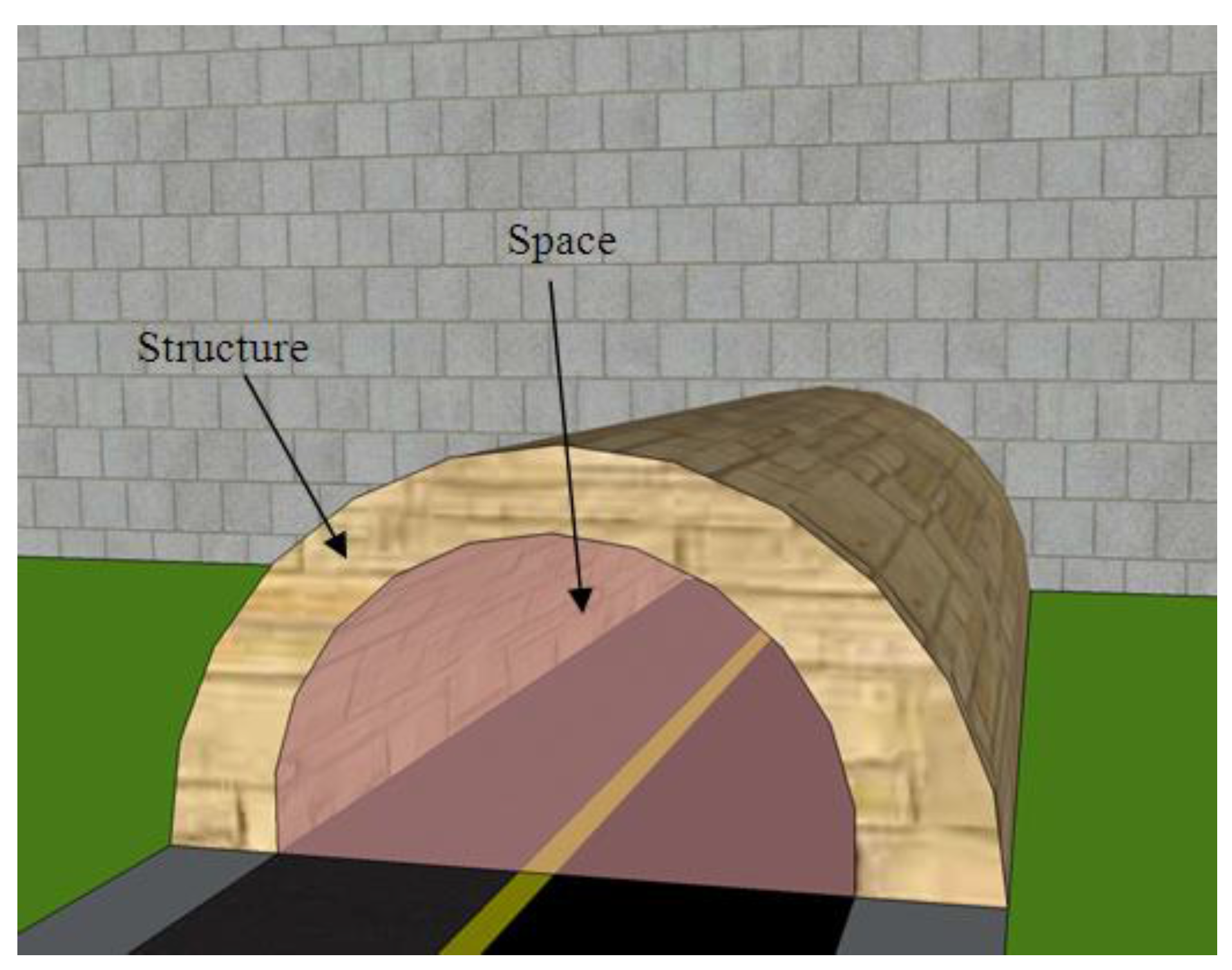
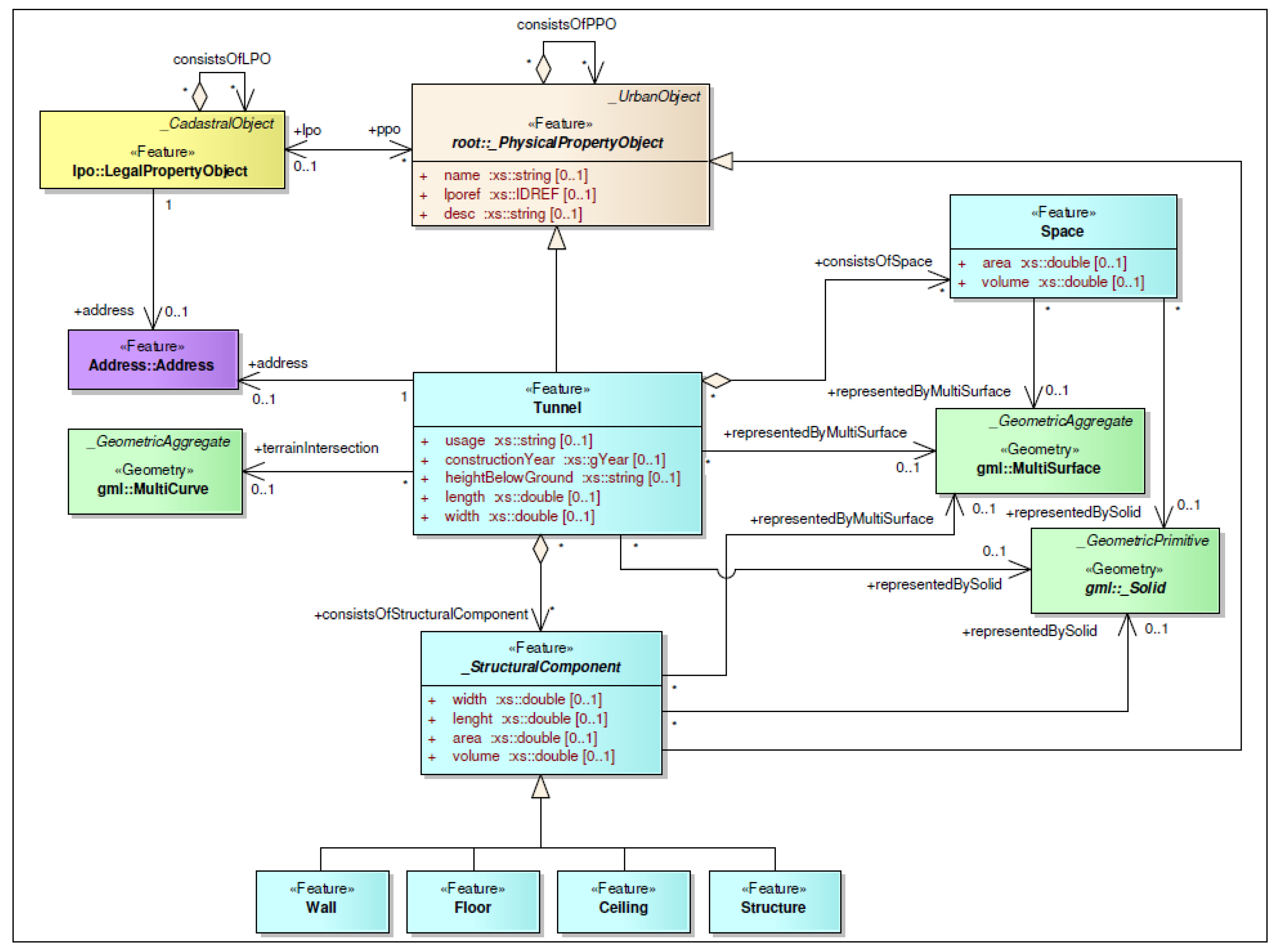
3.9. 3DCDM Tunnel Model
The
3DCDM model allows users to create the tunnel models and then link it to its legal counterparts. The
Tunnel model, such as
Building and
Land models, is located in the physical hierarchy of the
3DCDM model. The
Tunnel model has an abstract superclass
_PhysicalPropertyObject, which is associated with zero or one
LegalPropertyObject. The
Tunnel model can be created through three main subclasses. They are class
Tunnel, class
Space, and abstract class
_StructuralComponent (
Figure 19). A tunnel is not always an underground object and it could be a walkway that connects buildings above street.
Tunnel
The class
Tunnel describes the physical shape (without internal components) of a tunnel. The class
Tunnel is a 3D object and is created using
gml:_Solid or
gml:MultiSurface geometry object. In the
3DCDM model, the intersection lines of a tunnel and terrain surfaces is represented using
gml:MultiCurve. The class
Tunnel is associated to the class
Address to specify the physical address of a tunnel (
Figure 19).
Space
Each tunnel can be created using zero or more spaces. The class
Space defines the internal volumetric space of a
Tunnel.
Space is a 3D object and can be represented using
gml:MultiSurface or
gml:_Solid (
Figure 19). Attributes of the class Space in
Tunnel model are similar to attributes of the class
Space in the
Building model.
_StructuralComponent
Each tunnel can be created using zero or more
_StructuralComponent. The abstract class
_StructuralComponent in the
Tunnel model is similar to the abstract class
_StructuralComponent in
Building model.
Figure 20 illustrates how a tunnel consists of structures and a space.
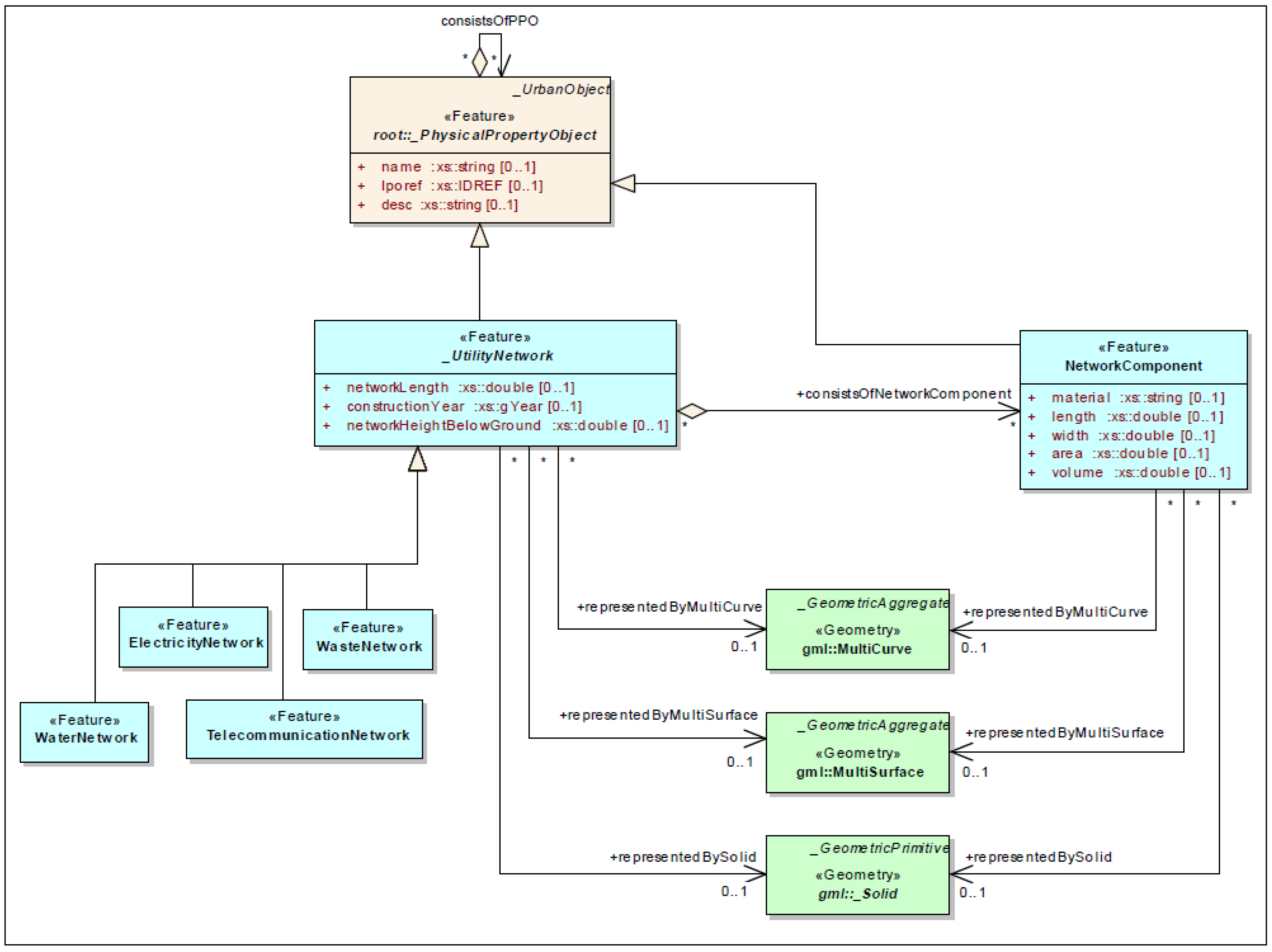
3.10. 3DCDM UtilityNetwork Model
The
3DCDM model allows users to create the utility network models and then link it to its legal counterparts. The
UtilityNetwork model can be created through two main subclasses. They are abstract class
_UtilityNetwork and class
NetworkComponent (
Figure 21).
_UtilityNetwork
The abstract class
_UtilityNetwork and its specialisations such as
ElectricityNetwork,
WaterNetwork,
TelecommunicationNetwork, and
WasteNetwork are used to model the internal sections of a utility network. The abstract class
_UtilityNetwork is associated to the class
Address to specify the physical address of a utility network (
Figure 21).
Each _UtilityNetwork can be represented directly using GML geometric objects or can be represented by various network components.
NetworkComponent
Each utility network can be created using zero or more
NetworkComponent. The class
NetworkComponent defines the structures that are used to create the
_UtilityNetwork. Each
NetworkComponent can be represented using
gml:MultiCurve,
gml:MultiSurface, or
gml:_Solid (
Figure 21).
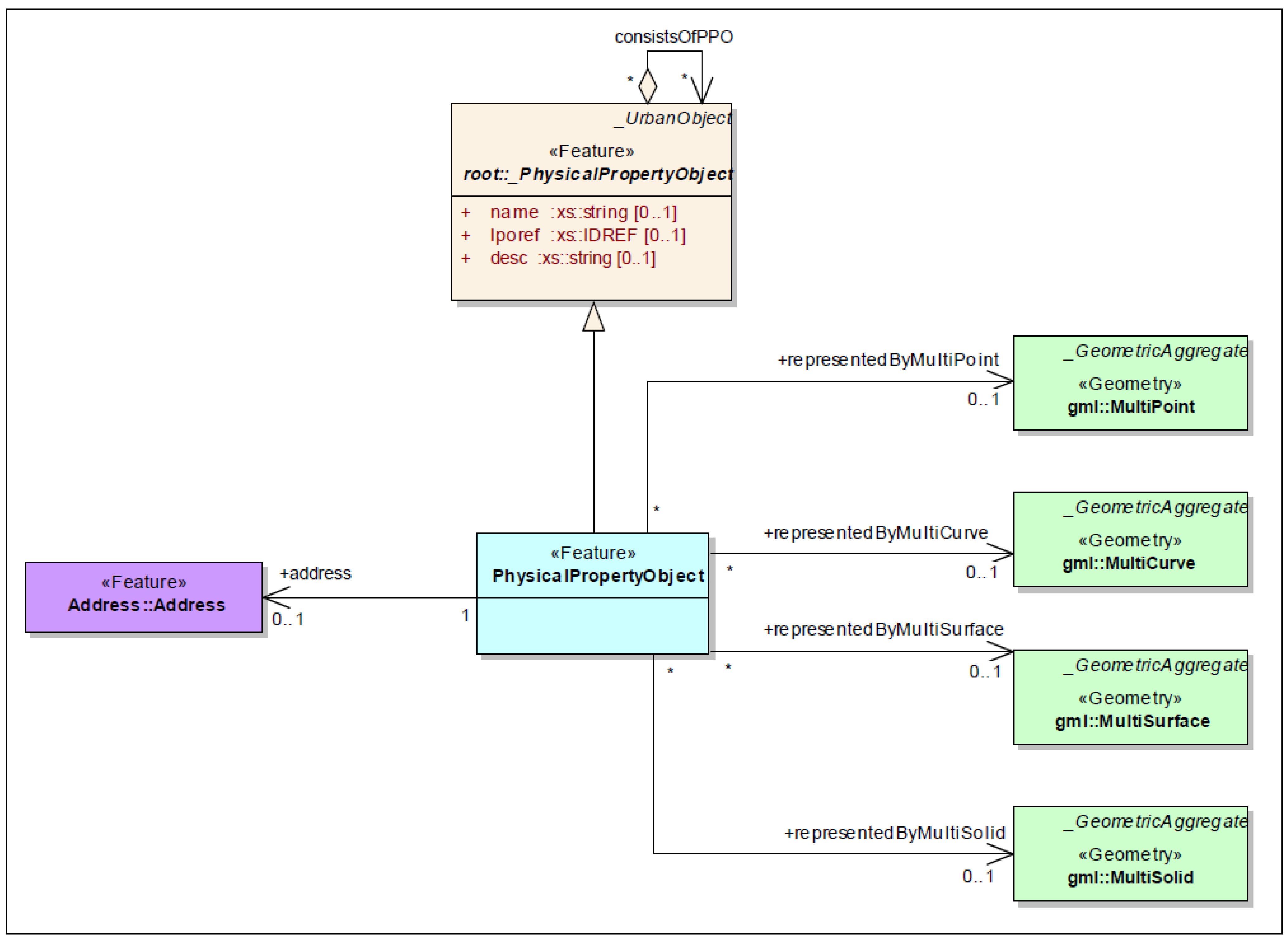
3.11. 3DCDM PhysicalPropertyObject Model
In the
3DCDM model, the
PhysicalPropertyObject is designed to model unknown urban objects, which need to be created to link to their corresponding legal objects. If the physical property object were none of the existing physical models in the
3DCDM (it is not a
Building,
Land,
Tunnel, nor
_UtilityNetwork models),
PhysicalPropertyObject model would be used to model this urban object. The
PhysicalPropertyObject model has an abstract superclass
_PhysicalPropertyObject that is associated with zero or one
LegalPropertyObject. The
PhysicalPropertyObject model has one subclass that is class
PhysicalPropertyObject (
Figure 22).
PhysicalPropertyObject
The class
PhysicalPropertyObject is used to model any unknown urban object that is not included in the model. Each
PhysicalPropertyObject can be represented directly using GML geometric objects. The class
PhysicalPropertyObject is associated to the class
Address to specify the physical address of an urban object (
Figure 22).
Figure 19.
The UML diagram of 3DCDM Tunnel model.
Figure 19.
The UML diagram of 3DCDM Tunnel model.
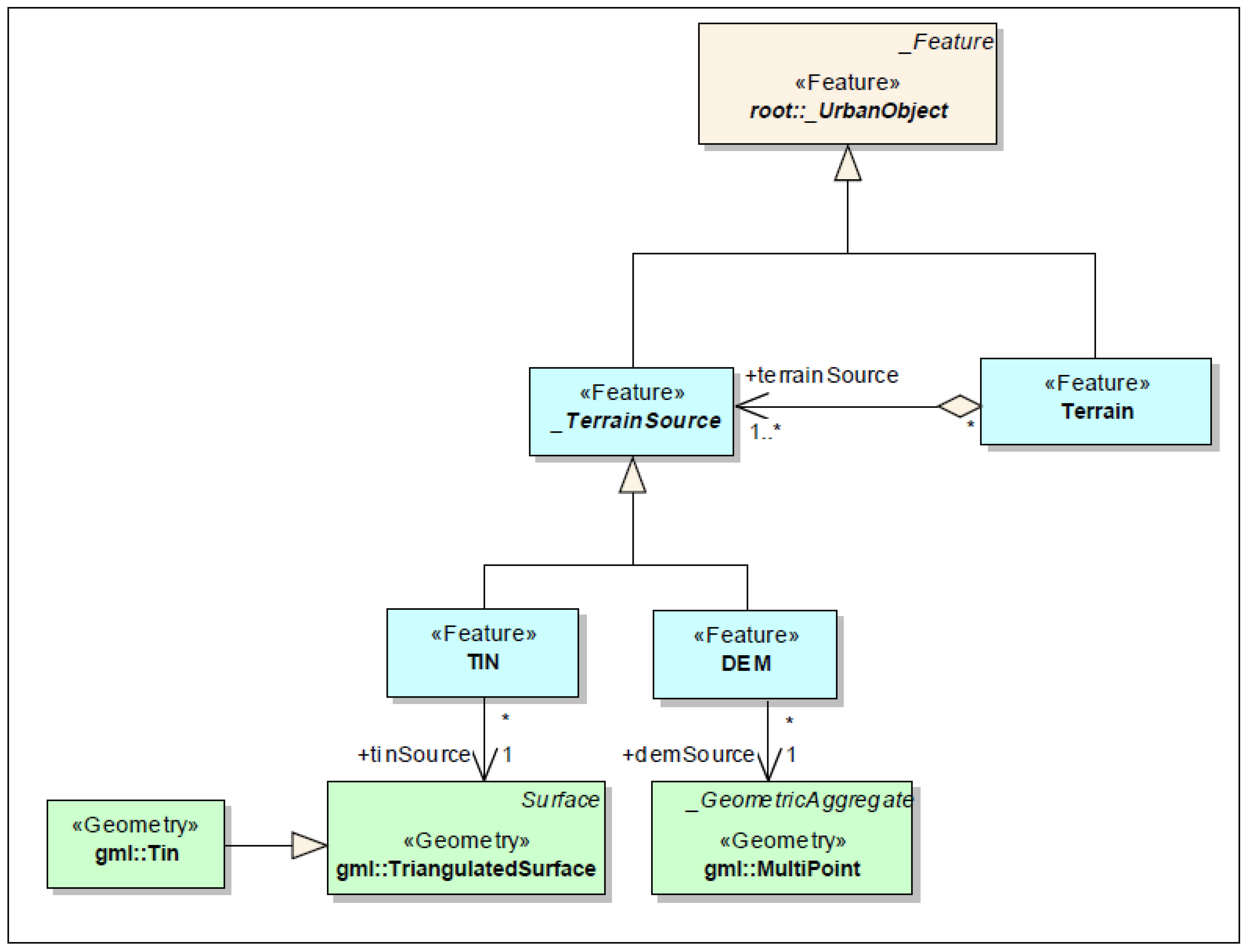
3.12. 3DCDM Terrain Model
Terrain or surface ground is an important part of the physical world. It is also an essential feature for cadastral applications. A combination of terrain and land ownership right objects provides a more realistic representation of the legal world. 2.5D cadastres, representations of land parcels on a 3D ground surface, are a long term practice in the land administration domain [
30,
31]. 3D cadastres, a combination of 3D parcels with the terrain model, will represent more realistic legal models and facilities to better understand the location and boundaries of land ownership objects, especially when they are located below the ground surface. The
3DCDM supports the terrain model.
Figure 23 illustrates the UML diagram of the terrain model in the
3DCDM.
Figure 20.
Example of a tunnel model consists of structural components and a space.
Figure 20.
Example of a tunnel model consists of structural components and a space.
Figure 21.
The UML diagram of 3DCDM UtilityNetwork model.
Figure 21.
The UML diagram of 3DCDM UtilityNetwork model.
Figure 22.
The UML diagram of 3DCDM PhysicalPropertyObject model.
Figure 22.
The UML diagram of 3DCDM PhysicalPropertyObject model.
Terrain
In the
3DCDM, the terrain is represented by the class
Terrain.
Terrain is subclasses of Abstract class
_UrbanObject (
Figure 23).
TerrainSource
Terrain consists of one or more entities of class
TerrainSource.
TerrainSource are subclasses of Abstract class
_UrbanObject (
Figure 23).
TIN
In
3DCDM, the terrain can be represented as a Triangulated Irregular Network (TIN).
TIN is created using GML geometry class
gml:Tin (
Figure 23).
DEM
The terrain can be represented as a multiple 3D points or
DEM in the
3DCDM model.
DEM is created using GML geometry class
gml:MultiPoint (
Figure 23).
Figure 23.
The UML diagram of 3DCDM terrain model.
Figure 23.
The UML diagram of 3DCDM terrain model.
Figure 24.
Code lists of the 3DCDM model.
Figure 24.
Code lists of the 3DCDM model.
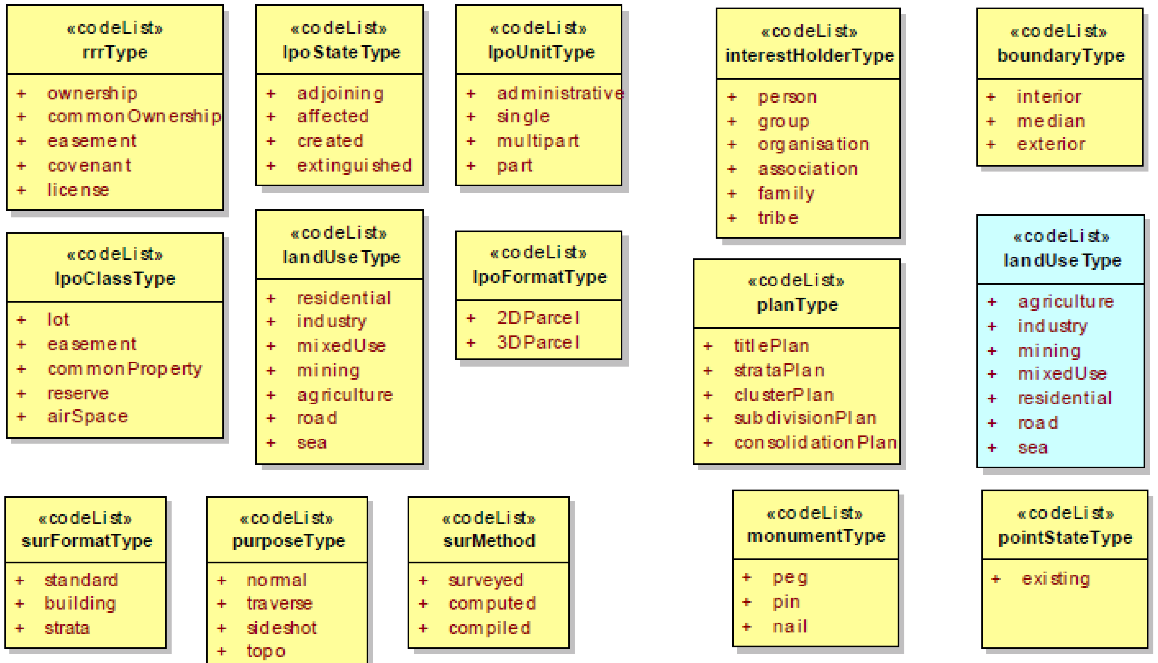
3.13. Code Lists of the 3DCDM Model
Code lists are used to describe different enumeration of a data model. They represent the possible examples of the values. They are open and can be extended.
Figure 24 shows the code lists used in the 3DCDM model.
4. Evaluation of the 3DCDM Model
In order to evaluate the
3DCDM model, the conceptual model quality evaluation framework is used to investigate different aspects of the
3DCDM model. This framework provides certain principles and quality factors which can be used to evaluate the
3DCDM model. These principles and quality factors state that data models should [
32]:
meet the data requirement
be clear and unambiguous to all (not just the authors)
be stable in the face of changing data requirements
be flexible in the face of changing business practices
be reusable by others
be consistent with other models covering the same scope (if they were developed following these principles)
be able to integrate data from different data models.
Quality of models is very important because models represent user requirements and are used as bases for building systems. Model quality is considered from two perspectives; process quality and product quality [
33].
For product quality, the focus is on characteristics of the final product. It is used to inspect the problems and deficiencies of the final product. While the process quality does not focus on the final product, its focus is on the process which is used to build the product [
34].
An international standard has now been established for evaluating the quality of software products. However there is no equivalent standard for evaluating the quality of conceptual models. While a range of quality frameworks have been proposed in the literature, none of these have been widely accepted in practice and none has emerged as a potential standard [
32].
Various quality evaluation frameworks have been developed such as [
35,
36,
37,
38,
39]. Among them, Moody [
40] developed a conceptual model quality evaluation framework which highlights eight quality factors: completeness, integrity, flexibility, understandability, correctness, simplicity, integration, and implementability. Every factor has a detailed metric for its evaluation. This framework was applied to ensure process quality in this research. Various review meetings were held during the model development stage.
The definitions of the quality factors are [
40]:
Correctness was defined as whether the model conforms to the rules of the data modelling technique (i.e., whether it is a valid data model). This includes diagramming conventions, naming rules, definition rules, rules of composition, and normalisation.
Completeness refers to whether the data model contains all information required to support the required functionality of the system.
Integrity is defined as whether the data model defines all business rules that apply to the data.
Simplicity means that the data model contains the minimum possible entities and relationships.
Flexibility is defined as the ease with which the data model can cope with business and/or regulatory change.
Integration is defined as the consistency of the data model with the rest of the organisation’s data.
Understandability is defined as the ease with which the concepts and structures in the data model can be understood.
Implementability is defined as the ease with which the data model can be implemented within the time, budget, and technology constraints of the project.
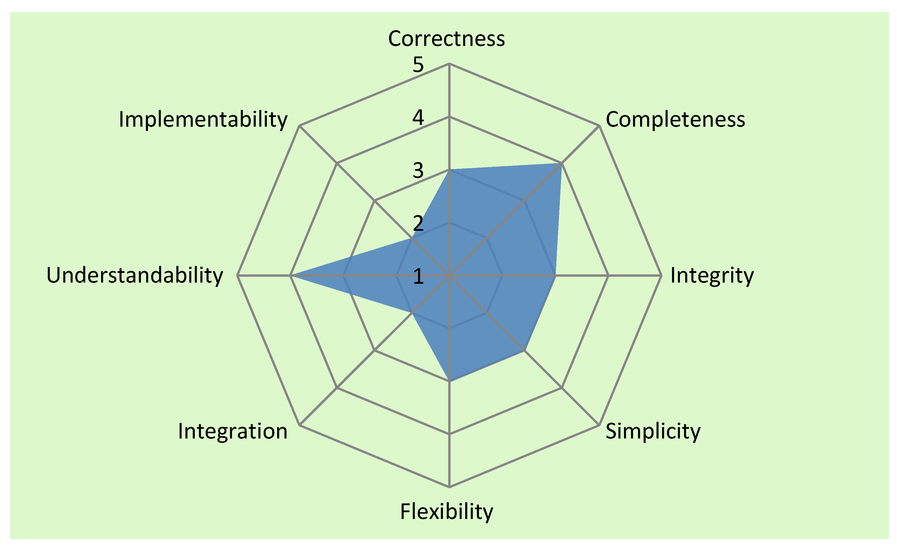
Table 1.
The 3DCDM model quality factors.
Table 1.
The 3DCDM model quality factors.
| Quality Factor | Description | Rate (1 = poor; 5 = excellent) |
|---|
| Correctness | The 3DCDM model was developed based on the ISO/TC standard 19103:2006 (Geographic information-Conceptual schema language) and conforms with its technical specifications.
The 3DCDM model follows diagramming conventions, naming rules, and all other necessary conditions. However, the 3DCDM model requires inspection by a professional data modeller. | 3 |
| Completeness | The 3DCDM model was developed based on the business analysis. In this stage, the model supports most of the user requirements of the 3D cadastres. Requirements are changing. Therefore, it is essential to update the user requirements after developing the 3DCDM model. | 4 |
| Integrity | In this stage, the 3DCDM model defines limited business rules that apply to the data. The 3DCDM model should be assessed by the users to identify how well the model defines the business rules. | 3 |
| Simplicity | The 3DCDM model contains the minimum possible entities and relationship mostly because it utilises the concept of Legal Property Object. However, the 3DCDM model requires inspection by a professional data modeller. | 4 |
| Flexibility | Fully functioning 3D cadastres are yet to be implemented the world. This model can facilitate the implementation of the 3D cadastre. Therefore, it is not possible to truly discuss how the model would cope with business changes. However the 3DCDM model was developed based on the idea that 3D cadastres should be developed in such a way that it can help other applications, such as property management and urban planning. | 4 |
| Integration | The 3DCDM model was developed for managing stratified land ownership rights. On the one hand, the 3DCDM model requires 3D data (X,Y,Z) to be able to create and represent the 3D models. On the other hand, architectural or engineering plans are required to create the physical object on the data model. However, most of the jurisdictions maintain limited 3D data or physical information. | 3 |
| Understandability | The 3DCDM model structure is easy to understand. The 3DCDM model supports semantics, which help to realise the different part of the model. | 4 |
| Implementability | Lack of the required data impedes the implementation of the 3DCDM model. Technology is not advanced in creating and manipulating of 3D models. Creating 3D models is time consuming and expensive. However, the 3DCDM model works well if the required data is available. | 4 |
Figure 25.
Subjective ratings of the 3DCDM model quality.
Figure 25.
Subjective ratings of the 3DCDM model quality.
In this framework, each quality factor is rated using a 1–5 scale (1 = poor; 5 = excellent), which was used by the model reviewers. The result of the overall subjective ratings can be presented in the form of Radar or Kiviat charts.
The
3DCDM was validated using a case study approach, which enabled the definition of quality factors. The
3DCDM was rated based on these factors by the project’s stakeholders and the results are listed in
Table 1. The overall rating of the
3DCDM model is 4. This is a satisfactory rating given the current lack of available and appropriate 3D data. However, it is likely that, with subsequent use, implementation, and relevant feedback the correctness value will improve over time. In the case study, a two-storey building was used to consider relevant legal (ownership boundaries, ownership information, common properties, and an easement) and physical information (the width, length, and height of walls, roofs, and ceilings). An arbitrary coordinate system was used to extract all coordinates of the required points. From these points various properties, such as width and length of the walls and units, were determined. This information was then inserted into the appropriate XML schemas such as
Building,
LegalpropertyObject,
InterestHolder,
Survey,
CadastralPoints, and
Terrain to demonstrate the validity of the
3DCDM to model and produce the 3D legal objects of the building and their physical counterparts. The result of this exercise showed that all 3D legal objects of the building and their corresponding physical objects can be effectively modelled using the
3DCDM model.
Figure 25 illustrates the result of the overall subjective ratings of the
3DCDM model, which is represented in a Radar chart.
The subjective ratings shown in
Figure 25 clearly indicate what the strengths and weaknesses are in the model. Ratings below 3 are considered “poor” and ratings above 3 are “good”. This provides feedback to the analyst as to where the model needs to be improved. Subjective quality ratings are useful for improving the quality of the model, choosing between alternatives and comparison over time improves processes.
6. Conclusions
Integration of legal and physical objects in virtual 3D city models and cadastral data models increases the usability of the data models. They can support various applications such as land development processes and 3D cadastres that require both legal and physical information. Few researchers investigated to extend CityGML and BIM to support legal objects; however, no cadastral data models extended to fully support physical objects.
This paper proposes the 3DCDM model that is developed based on the core cadastral data models and extended to support urban physical objects. The conceptual and logical models of the 3DCDM are presented in detail. The aim is to explore all elements and components of the 3DCDM model, including its classes, attributes, and associations.
For this purpose, the package view of 3DCDM was presented at the first step to provide the overall view of the 3DCDM’s components. They are separated into two hierarchies in the 3DCDM model: legal and physical.
Then, 12 sub-models or modules of the 3DCDM were presented, including 3DCDM Geometry Model, 3DCDM Root Model, 3DCDM LegalPropertyObject Model, 3DCDM InterestHolder Model, 3DCDM Survey Model, 3DCDM CadastralPoints Model, 3DCDM Building Model, 3DCDM Land Model, 3DCDM Tunnel Model, 3DCDM UtilityNetwork Model, 3DCDM PhysicalPropertyObject Model, and 3DCDM Terrain Model.
Sub-models are selected based on the user requirements and the application. For example, if the purpose of using the 3DCDM is to model a building, only 3DCDM Building Model and 3DCDM Root Model are used. The 3DCDM Root Model must be used in each implementation of the 3DCDM model. Since each jurisdiction has different cadastral requirements, the data model should be modified to meet those requirements.
The 3DCDM was validated by the project’s stakeholders. However, further research is required to validate the model and examine approaches to implementation. Also, modelling legal objects in different LODs needs more investigation. The logical model of the 3DCDM is utilised as a base to develop the physical model of the 3DCDM.


