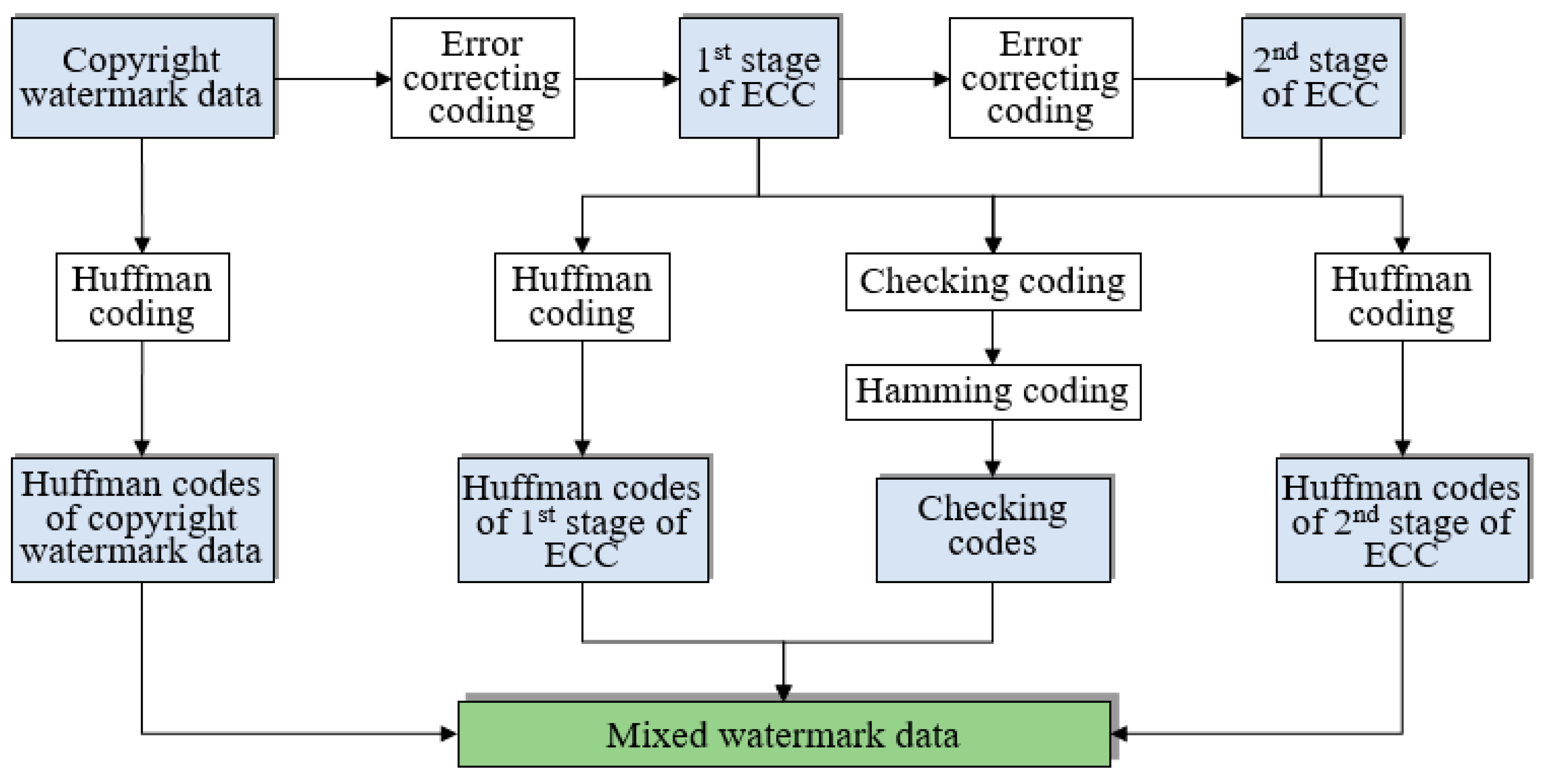
The proposed scheme will be described in three stages in this section. The designed algorithm of vertex grouping and watermark embedding will be introduced first, and the process of watermark extraction and map content recovery will be described in detail afterwards. Finally, the method of self-optimization of watermark data after watermark extraction will be explained minutely.
4.1. Vertex Grouping and Watermark Embedding
Map vertices are grouped first in this section by feature vertex extraction. Then, the given mixed watermark data will be separated into four individual parts, i.e., copyright watermark data, the first stage of ECC, the second stage of ECC and Hamming codes. Afterwards, the obtained Hamming codes will be embedded into feature vertices, and copyright watermark data and two stages of ECCs will be embedded into non-feature vertices. Finally, the watermarked feature vertices and non-feature vertices will be combined to generated the watermarked vector map.
Given the original vector map and the mixed watermark data, the procedure of vertex grouping and watermark embedding is shown in
Figure 6, which can be summarized as the following steps:
Step 1. Extract feature vertices of the original vector map adopting the
algorithm [
3], and then allocate all map vertices to a feature vertex set
and a non-feature vertex set
.
Step 2. Separate the given mixed watermark data into four individual parts, i.e., copyright watermark data , the first stage of ECC , the second stage of ECC and Hamming codes .
Step 3. Establish correspondence between elements in
and
. The virtual reference vertex of the original vector map, assumed
, will be determined first according to Equation (3), where
is the integer part of the coordinate of
and
denotes the rounding function. Afterwards, for each
, the corresponding Hamming code
can be determined according to Equation (4), where
is an existing function that can transform inputs with arbitrary lengths into outputs with fixed lengths, and
and
are integer parts of
and
, respectively.
Step 4. Combine elements in
,
and
into one large code list, assumed
. Establish correspondence between elements in
and
. For each
, the corresponding watermark bit
can be determined according to Equation (5), where
is an existing function that can transform inputs with arbitrary lengths into outputs with fixed lengths, and
and
are integer parts of
and
, respectively.
Step 5. Embed each bit in
into its corresponding feature vertices in
, and a watermarked feature vertex set
can be obtained. Take a feature vertex
and its corresponding Hamming code
as an example, and the embedding process can be completed by the following sub-steps, i.e., (i) calculate the polar coordinate of
by Equation (6) (let
be the obtained polar coordinate), (ii) embed
into
by Equation (7) where
denotes the strength of watermark embedding and (iii) convert the watermarked polar coordinates
into rectangular ones
by Equation (8).
For example, if
,
and
, then
Step 6. Embed all bits in into non-feature vertices in by the same method as that described in Step 5, and a watermarked non-feature vertex set can be obtained. Combine all vertices in and to obtain the final watermarked vector map.
4.2. Watermark Extraction and Map Content Recovery
As shown in
Figure 7, the process of watermark extraction and map content recovery is the inverse one of watermark embedding, and the details are described as follows:
Step 1. Extract feature vertices of the watermarked vector map and allocate all map vertices into a feature vertex set
and a non-feature vertex set
, as described in Step 1 of
Section 4.1.
Step 2. Determine the virtual reference vertex of the watermarked vector map, assumed
, by Equation (9), where
and
are integer parts of
and
, respectively.
Step 3. Extract watermarks from vertices in
and recovery map content. For each
, the corresponding watermark bit
can be extract by the following sub-steps, i.e., (i) calculate the polar coordinate of
by Equation (10), (ii) extract
from the obtained polar coordinate by Equation (11) where
is a function getting the integer part of a decimal number, (iii) create a list
to store the extracted watermark bits, and the correspondence between watermark bits and elements in
can be constructed by the method mentioned in Step 3 of
Section 4.1 (a simple statistical method, i.e., the minority is subordinate to the majority, is adopted here for optimal value selection), (iv) obtain the recovered polar coordinate of
, assumed
, by Equation (12) where
is a function getting the fraction part of a decimal number and (v) convert the recovered polar coordinates of
into rectangular ones by Equation (13).
Take the data in Step 5 of
Section 4.1 as an example, i.e.,
and
, and the watermark bit can be extracted by
Then, the map content can be recovered by
Step 4. Extract watermarks from vertices in by the same method as that described in Step 3. Copyright watermark data and two stages of ECCs can be obtained, and watermarked non-feature vertices can be recovered.
Step 5. Combine the recovered map vertices to generate the recovered vector map. Similarly, combine the obtained Hamming codes, copyright watermark data and two stages of ECCs to generate the extracted mixed watermark data.
4.3. Self-Optimization of Watermark Extracting Results
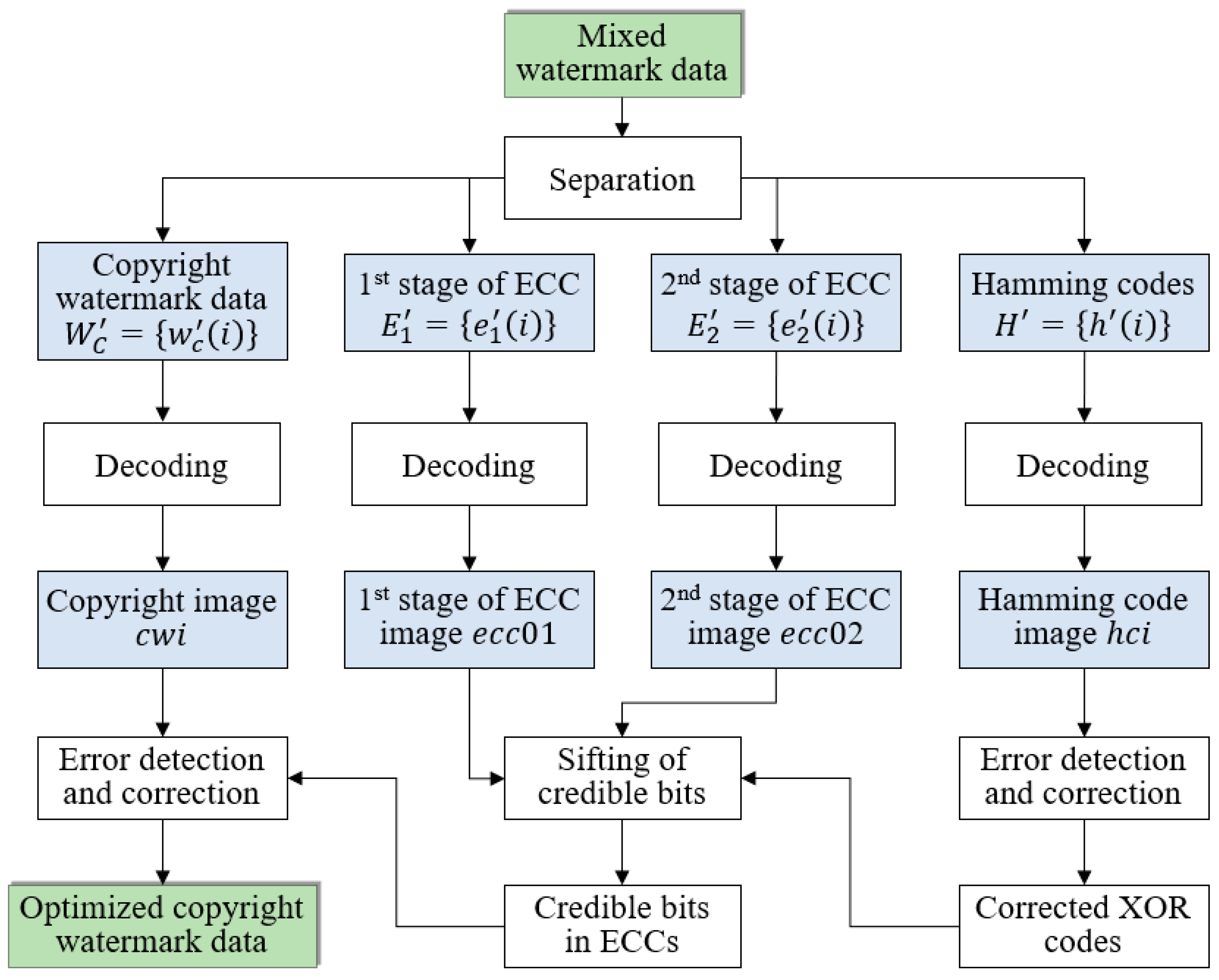
After watermark extraction, the accuracy of copyright watermark detection can be further improved in this paper from the perspective of the self-error-correction of mixed watermark data. Given the extracted mixed watermark data, the self-optimization procedure (
Figure 8) can be summarized as follows:
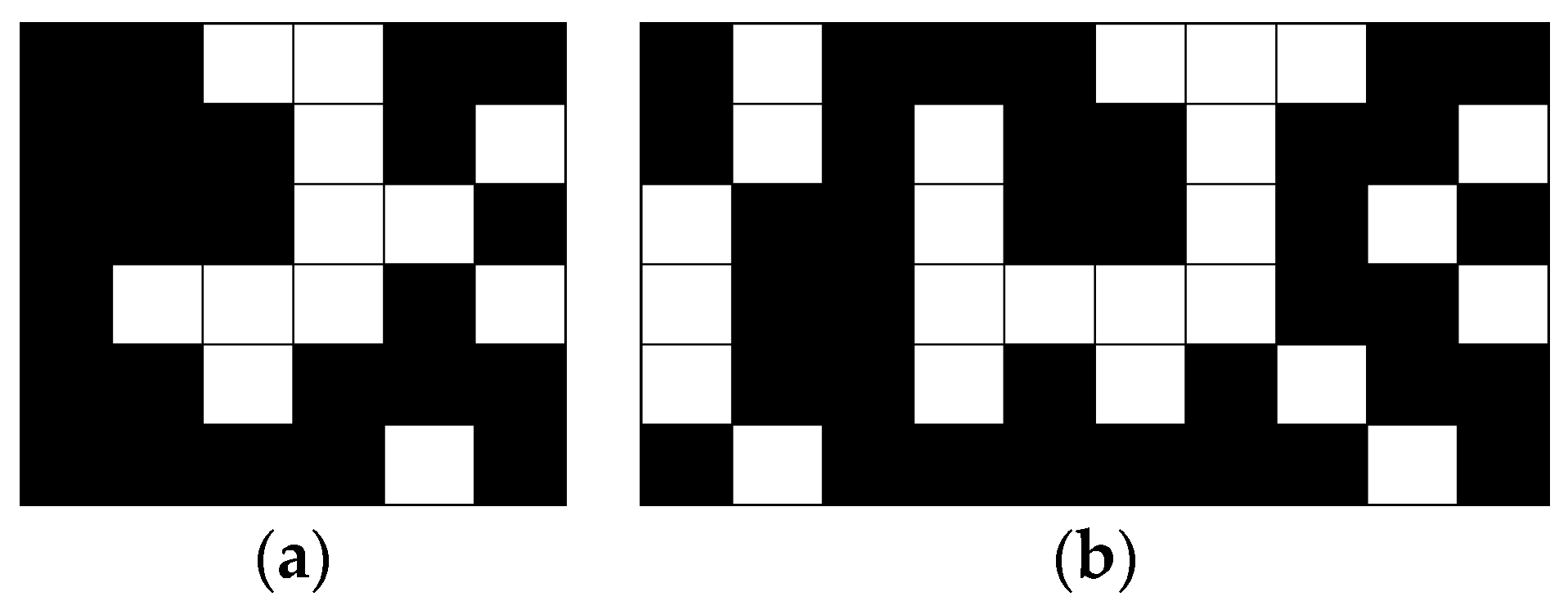
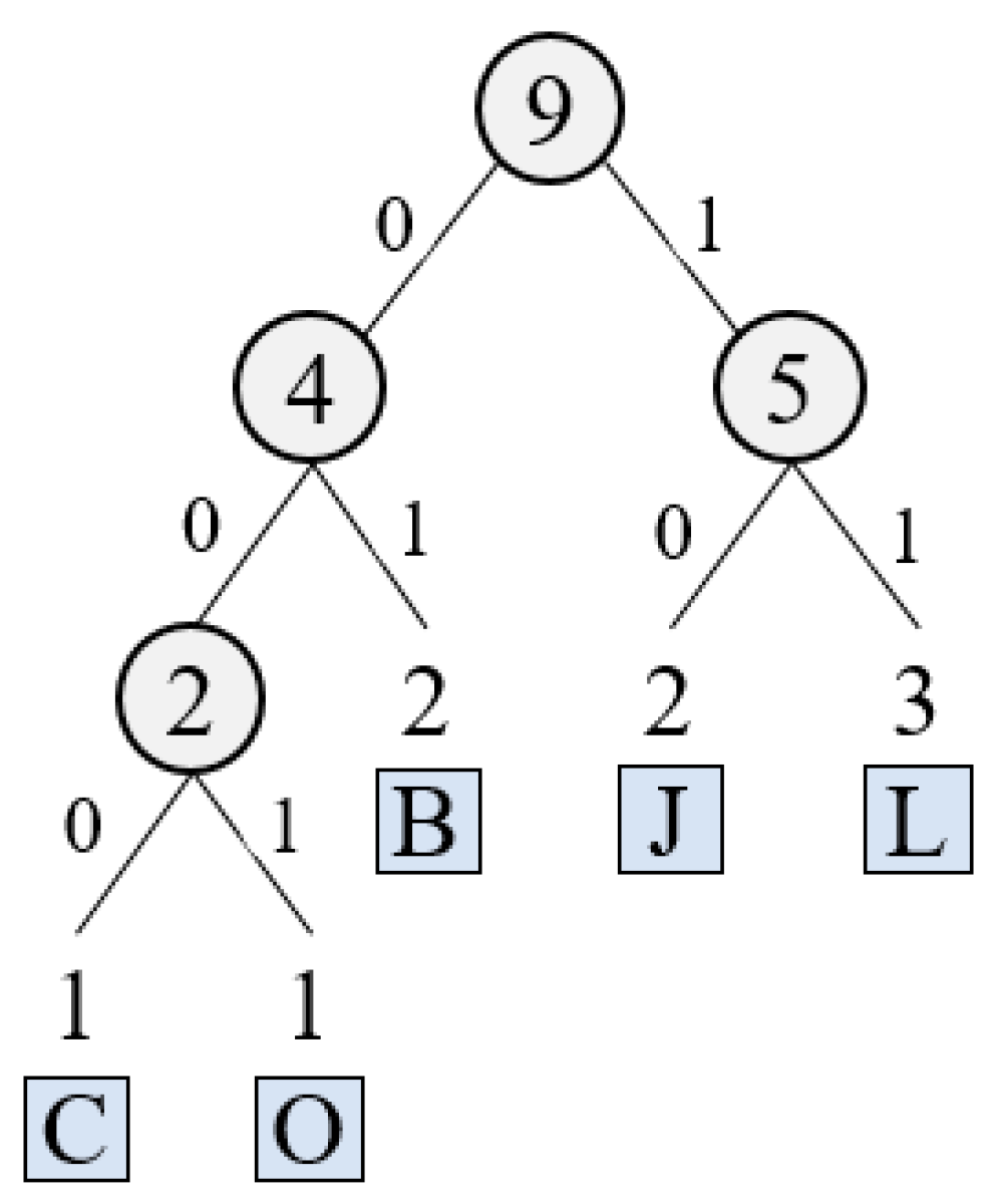
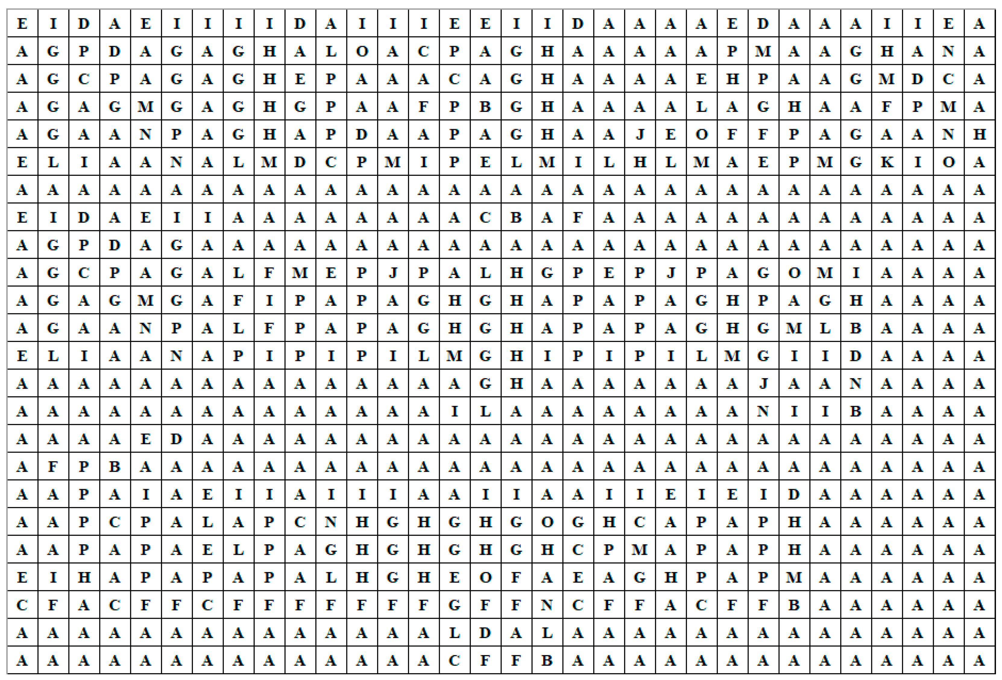
Step 1. Separate the mixed watermark data into four parts, i.e., copyright watermark data, first stage of ECC, second stage of ECC and Hamming codes. Then, decode the four parts, replacing each code by its corresponding
block (the correspondence is shown in
Table 1). Then, four binary images can be obtained, assumed
(copyright watermark image),
(first stage of ECC),
(second stage of ECC) and
(Hamming code image).
Step 2. Detect and correct error elements in , taking each row as a unit. For each unit, assumed , the process of error bit detection and correction can be completed by the following sub-steps:
- (i)
Calculate the number of redundant bits and position them using the same formula as in Step 4 of
Section 3.1.
- (ii)
Parity checking. Calculate parity bits based upon the data bits and the redundant bits using the same rule as in Step 4 of
Section 3.1. Thus, let
be the first redundant bit and
. The other redundant bits can be ascertained similarly.
- (iii)
Detect and correct error bits. Calculate the decimal equivalent of the parity bits (binary values) first. If it is 0, there is no error. Otherwise, the decimal value gives the bit position that has an error. For example, if , it implies that the data bit at position 9, decimal equivalent of 1001, has an error. Then, flip the bit to get the correct bit value.
Step 3. Obtain the corrected XOR code by eliminating redundant bits from the optimized . All positions of redundant bits are calculated in sub-step (i) of Step 2.
Step 4. Choose credible bits in , and the obtained XOR codes (assumed ). For each , and , if and is a white pixel, they will be considered “credible” or they will be considered “incredible”.
Step 5. Correct incredible bits in . For each incredible , if and are all credible, then it can be corrected: if is a black pixel, let or assign by flipping .
Step 6. Detect and correct error bits in based on the corrected . Firstly, choose credible bits from . For each , it will be considered credible if the total number of black pixels in , , and is an odd (resp. even) number or it will be considered incredible. Afterwards, correct incredible bits in . For each incredible , if one of the following conditions is satisfied, i.e., (i) , and are all credible, (ii) , and are all credible and (iii) , and are all credible, it can be corrected according to the rule that the total number of black pixels in the aforementioned four pixels is an odd (resp. even) number.
