Article

Serverless Geospatial Data Processing Workflow System Design

by
Mete Ercan Pakdil
1,* and
Rahmi Nurhan Çelik
2
1
Geographical Information Technologies Program, Institute of Informatics, Istanbul Technical University, Istanbul 34469, Turkey
2
Geomatics Engineering Department, Istanbul Technical University, Istanbul 34469, Turkey
*
Author to whom correspondence should be addressed.
ISPRS Int. J. Geo-Inf. 2022, 11(1), 20; https://doi.org/10.3390/ijgi11010020
Submission received: 25 October 2021 / Revised: 12 December 2021 / Accepted: 26 December 2021 / Published: 30 December 2021

Abstract

:
Geospatial data and related technologies have become an increasingly important aspect of data analysis processes, with their prominent role in most of them. Serverless paradigm have become the most popular and frequently used technology within cloud computing. This paper reviews the serverless paradigm and examines how it could be leveraged for geospatial data processes by using open standards in the geospatial community. We propose a system design and architecture to handle complex geospatial data processing jobs with minimum human intervention and resource consumption using serverless technologies. In order to define and execute workflows in the system, we also propose new models for both workflow and task definitions models. Moreover, the proposed system has new Open Geospatial Consortium (OGC) Application Programming Interface (API) Processes specification-based web services to provide interoperability with other geospatial applications with the anticipation that it will be more commonly used in the future. We implemented the proposed system on one of the public cloud providers as a proof of concept and evaluated it with sample geospatial workflows and cloud architecture best practices.

1. Introduction

Over the last decade, big geospatial data has become a vital trend in the industry as data collection techniques become easier and more accessible, and storage options have increased significantly at the same time. The new ways of geospatial data collection technologies such as drones, robots, and satellites have brought new data storage and processing requirements that are predicted to become more complex and demanding. These new requirements could be met with cloud computing technologies. However, these new technologies could also have a learning curve for geospatial data scientists and analysts. Reducing the complexity of cloud computing is essential for the geospatial community to use efficiently for geospatial analyses. Classical geospatial data computation systems mostly run on on-premise platforms with limited computational capacity or storage. It is also challenging to maintain these infrastructures to provide sustainable service. On the other hand, having such a dedicated infrastructure is also an expensive investment for single usage or a limited number of processes. Cloud computing platforms are presented as a solution for these problems; however, leveraging cloud computing technologies needs expertise in this area at a certain level [1].
The cloud providers offer various models that provide different levels of abstraction and control on resources [2]. The infrastructure-as-a-Service (IaaS) model, where resource elasticity is realized at the virtual machine stage, offers large amounts of cloud resources to users, frequently with increased hosting costs over-provisioning or poor performance due to under-provisioning of resources [3]. Another model worth mentioning is Platform-as-a-Service (PaaS) which provides another abstraction level on top of the IaaS model. It removes managing the operating system. In both models, scalability and orchestration of application deployments are still the user’s responsibility (Figure 1). In Software-as-a-Service (SaaS) model, management responsibility on all layers is abstracted from the user.
The serverless paradigm is introduced to provide automated orchestration of deployment and scalable platform that runs based on demand [4]. It is similar to the SaaS model in layer abstraction, but it allows the developer to run any code on the serverless service. Even though it attracts developers because of its ease-of-use capabilities and cost efficiency, it is still a complex solution for most geospatial data processing scenarios to perform a workflow consisting of multiple steps. Each step in a geospatial data process workflow might require different computing power and amount of data [5]. A significant advantage of the serverless application does not use any resources when idle.
The serverless model could be described with a few disparate concepts. A commonly used concept called Function-as-a-Service (FaaS) provides a platform to run a custom code developed by a developer on a cloud platform without dealing with infrastructure management. FaaS applications are also run event-driven. They can execute the code in response to any events, such as smart sensor data or an event from another cloud service.
Another relatively new serverless concept is called Container-as-a-Service (CaaS) runs containers in a virtualization platform. A container consists of an application and operating system with installed dependencies to ensure running a bundled application on every platform as where it is initially developed. A CaaS service allows running containers without requiring virtualization platform management [6]. This service model offers more computational power and longer runtime than the FaaS model.
This paper proposes a data processing system design created explicitly for geospatial workflows to execute real-world scenarios on serverless platforms by leveraging both CaaS and FaaS models. We propose a solution that requires minimum infrastructure management and provides easy scalability by using serverless technologies. We observed that the CaaS model could handle complex geospatial tasks such as raster calculations by delivering more computational power and longer runtime. Our proposed system design has a container orchestration component to run custom-built containers that contain geospatial analysis codes on the CaaS model. This unique contribution makes our data processing system deployable entirely on serverless services, even for challenging geospatial tasks. In addition, another notable contribution is to propose workflow definition models to declare data processing flows easily to increase the useability of the system for non-technical users. These definition models can engage non-technical users to design and run geospatial workflows. Another significant contribution is to demonstrate how to use the new OGC API Processes specification with such a system to increase interoperability.
In this paper, we implemented a proof-of-concept to explore the applicability of the proposed system on a public cloud provider. In addition, we designed sample workflows to challenge the system with the most used complex and long-running processes in the geospatial field. Note that this is a challenging but worthwhile example to prove the system design could be used for both simple and complex workflows.

2. Related Works

Baldini et al. [7] reviewed the serverless paradigm by giving its characteristics and comparing different major cloud platforms. They mentioned that one of the drawbacks of the serverless approach is the risk of vendor lock-in, which makes the system highly dependent on a cloud provider’s services. They also observed that the importance of serverless technologies had not been recognized enough by the research community.
Kim et al. [8] proposed a framework called Flint to run PySpark based data processing jobs on Amazon Web Services (AWS) Lambda service without provisioning a cluster. They overcome long cold startup problems using the Python programming language, which is not dependent on runtime for execution. They also indicated memory and execution duration limitations in the AWS Lambda service.
Malawski et al. [9] studied a serverless architecture applied to scientific workflows. They have open-source HyperFlow software to run on cloud platforms that offer serverless services. They have proved that scientific workflows can be run on serverless architectures. Moreover, they stated that all scientific workflows are not feasible for serverless platforms because of some observations, such as resource management of tested cloud services such as AWS Lambda.
Lee et al. [10] reviewed serverless systems on cloud providers and compared their trade-offs with virtual machines. They also studied the dynamic behavior of serverless computing for the parallel execution of partitioned tasks over small function instances. They indicated that big data applications could be applied to serverless computing.
Ji et al. [11] evaluated the use of cloud computing for geospatial workflows. They discussed the applicability of their proposed architecture on grid computing with a case study. They concluded that large geospatial workflow applications could benefit from cloud computing with shorter runtime and on-demand resource provisioning.
Krämer et al. [12] developed a workflow management system that offers new workflow definition models similar to our proposed workflow definition models. They compared their definition models with other two existing well-known workflow management systems. Their study also shows that our simplified workflow definition models can increase usability and readability. They have examined the system in virtual machines in a cloud provider. We used only serverless services in the evaluation and designed our system deployable to any cloud provider offering serverless technologies.
Serverless Workflow [13] is an open-source project that provides a framework to run and design workflows to execute functions. The functions used in workflows exposes the Hypertext Transfer Protocol (HTTP) API endpoint to receive requests with arguments. The framework also has its declarative workflow language.

2.1. Cloud Workflow Services

Major cloud providers (Google Cloud, Microsoft Azure, Amazon Web Services) offer workflow solutions that enable serverless functions and containers to run tasks on them.
Amazon Web Services offers Amazon Step Functions (ASF) [14]. Workflow executions are programmed in the Amazon States Language, based on JSON (JavaScript Object Notation). It provides sequence, parallel, and decision controllers to design workflow. Moreover, it can call serverless functions (AWS Lambda) and containers (AWS Fargate) to execute pre-deployed codes on serverless platforms. It can transmit JSON data between steps. It also supports long-running processes and provides error handling features.
Microsoft Azure offers the Logic App service for workflow executions in a serverless way [15]. It supports calling Azure Functions to run pre-deployed code on Microsoft Azure’s FaaS platform. Furthermore, it has controller actions such as “switch”, “condition”, and “for each”. These actions allow routing workflow execution to different paths based on the conditions.
Google Cloud offers Google Cloud Workflows service [16]. Google Cloud Workflows are represented as steps with essential logical flow control such as conditions or loops. Every step makes an HTTP request that can be used, for example, to trigger a Google Cloud Function. It is not designed for broad parallel tasks as it lacks the map primitive present in other systems such as ASF.

2.2. Containerised Workflow Engines

There are open-source workflow engines that can also be deployed to any containerization platform. Container native engine enables setting up a workflow execution platform that can scale based on the demand and volume of the data to process. These engines take advantage of container systems. Containers are lightweight and packageable, and thus they can increase portability and efficiency in a workflow system [17].
Argo Workflows is a workflow engine for orchestrating parallel jobs on Kubernetes [18]. It is developed and maintained as an open-source project. Fundamentally, it parses and executes its custom declarative workflow definition that has its own rules and structure. Each step in the workflow corresponds to a container image run with inputs.
Kubeflow is another open-source project that runs machine learning workflows on Kubernetes with containers [19]. Kubeflow Pipelines is an add-on to Kubeflow that runs scalable end-to-end machine learning workflows. It can be deployed to cloud providers as well as on-promises. It requires additional tools to run workflow orchestration, such as Argo.

2.3. Review

Although the serverless computing paradigm is still a new concept and has become popular, previous serverless works have primarily focused on the limits of computation issues over the FaaS deployment model. Our proposed system explores the possibility of overcoming these issues by using the CaaS model.
As we reviewed that cloud providers have solutions for workflow management, trade-offs such as vendor-lock, quotas, limited supported technologies, and cost of execution should not be neglected.
We reviewed some well-known containerized workflow engines that can be deployed with the CaaS model. However, they are still complex solutions to build workflows for non-technical users. Our proposed solution also presents simple workflow definition models to simplify workflow design.

3. Materials and Methods

This section firstly explains our proposed workflow definition and task definition models used to define a workflow and a task declaratively. Next, we present a high-level component diagram of our proposed system and explain details of each component on the high-level diagram. We considered using only necessary components to reduce architecture and deployment complexity. We aimed to design the system loosely coupled with any specific software or vendor, and thus, we considered defacto and commonly available technologies in serverless platforms.

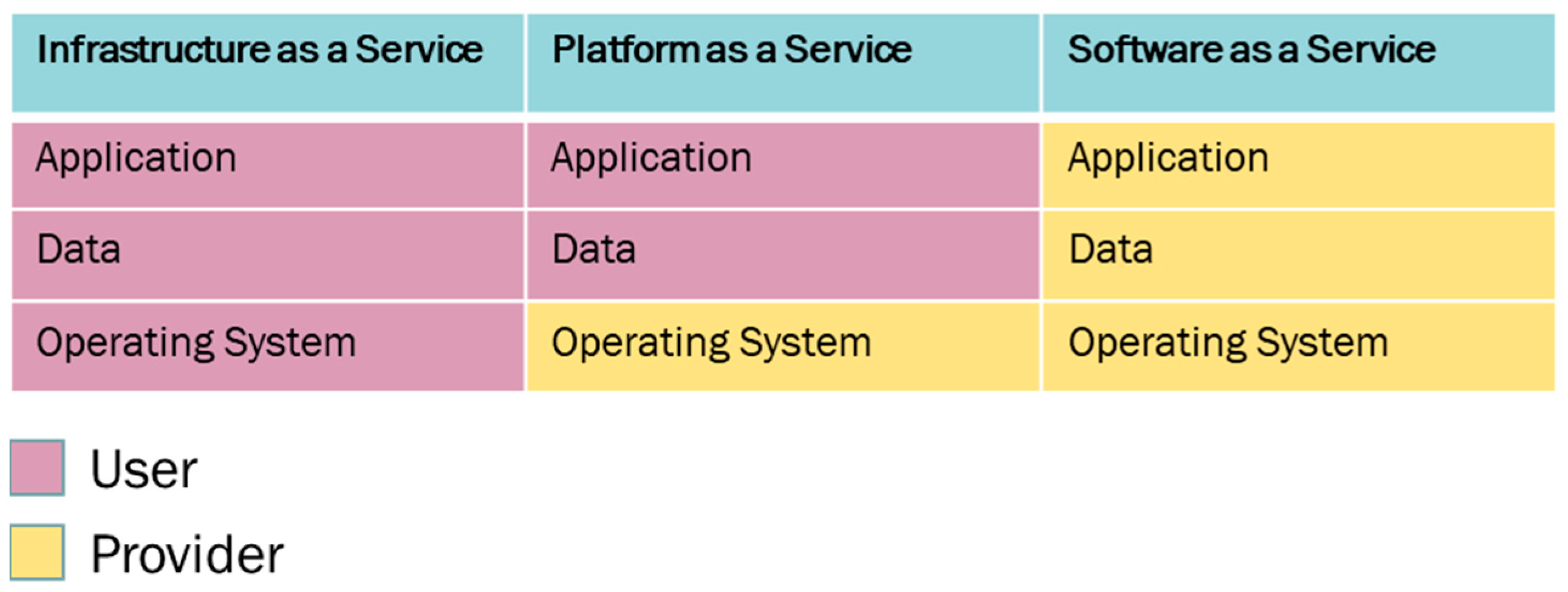
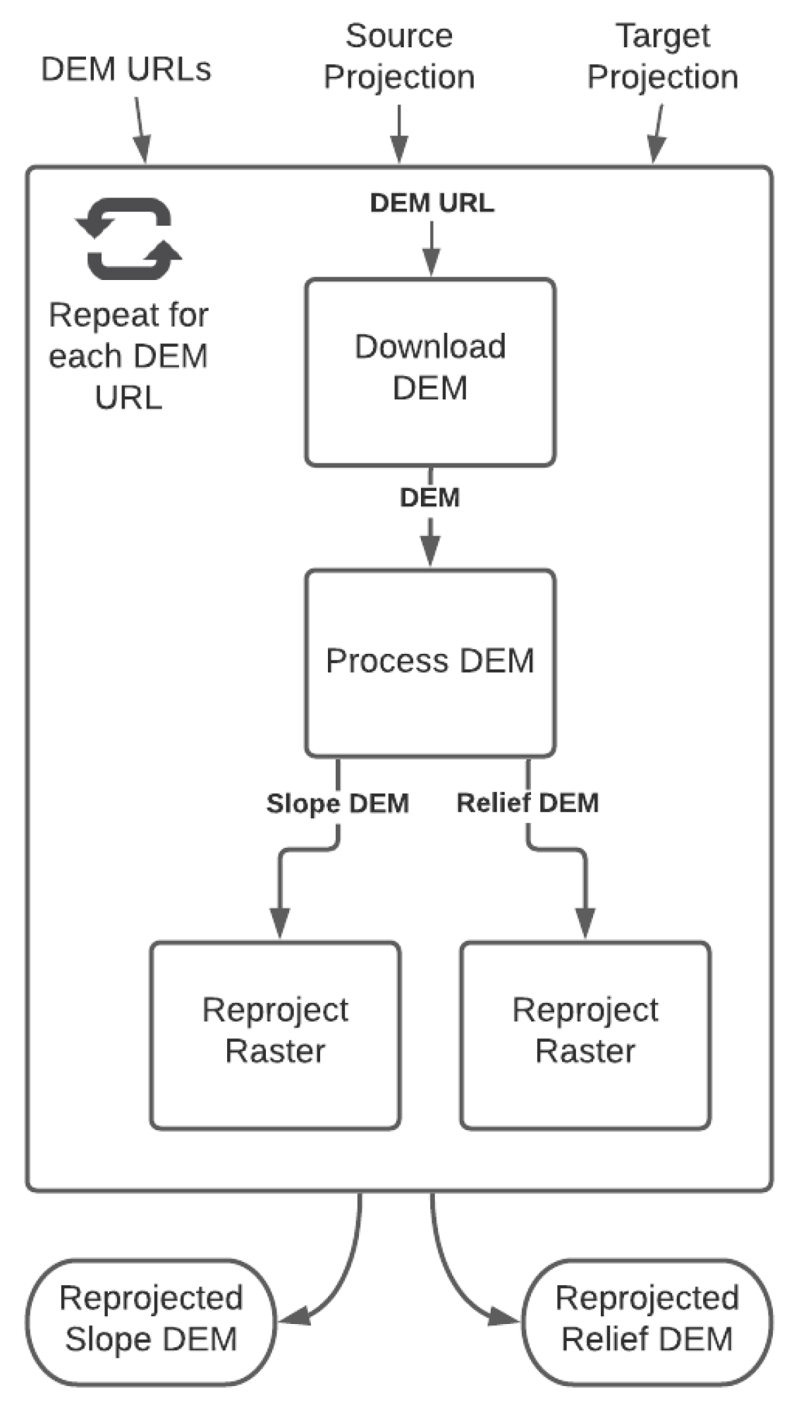
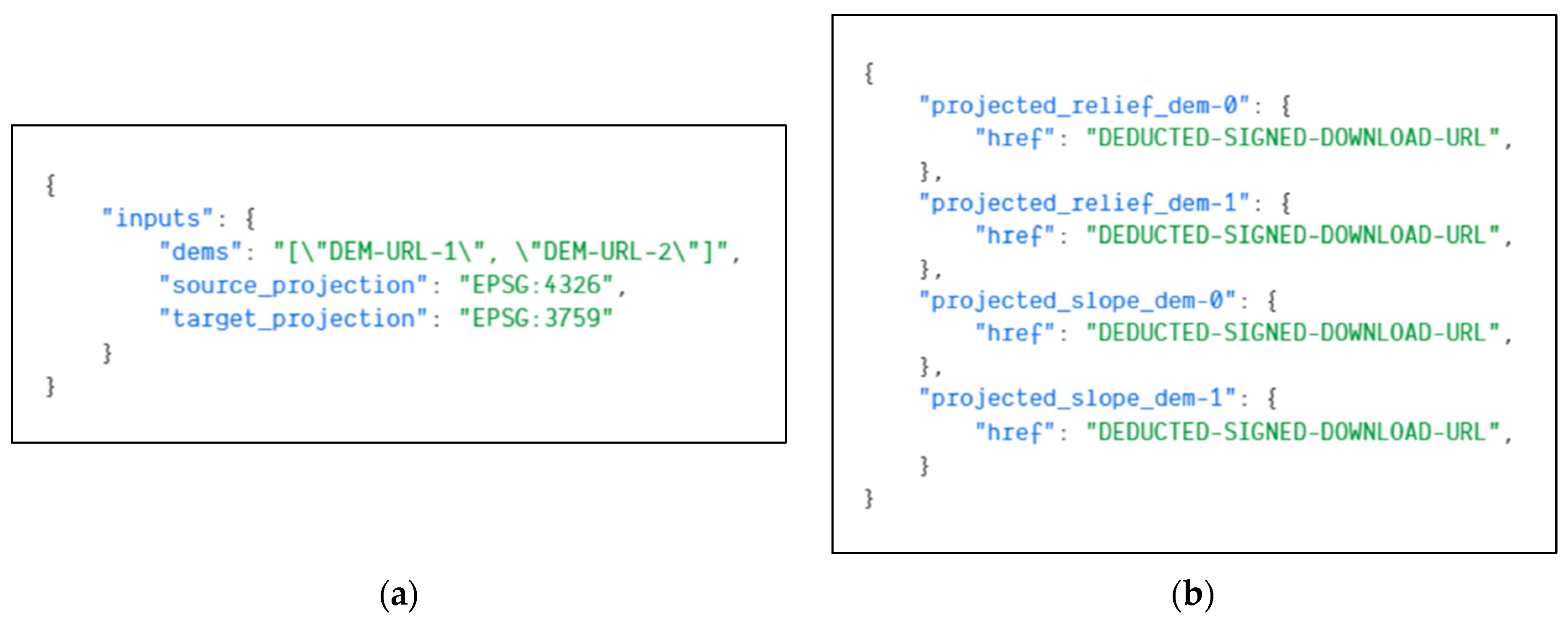
3.1. Workflow and Task Definition Models

Workflow definition models are commonly used to define data processing workflows with rules. They explain how a workflow engine executes tasks with validatable and interpretable rules [20]. In order to build a workflow system, we also needed to design new definition models to handle workflow requests in a standard way. We chose to use the Yet Another Markup Language (YAML) format for our proposed definitions because of its simplicity and readability. The YAML has become very popular because of its simple syntax and extensive support by programming languages [21]. YAML is considered a more human-readable language than other syntaxes such as JSON (JavaScript Object Notation) and XML (Extensible Markup Language).
Our proposed design introduced two types of definition models: task and workflow definition models. Each definition model has a different role and interpretation in the system. In the following subsections, our proposed definition models are explained in detail.

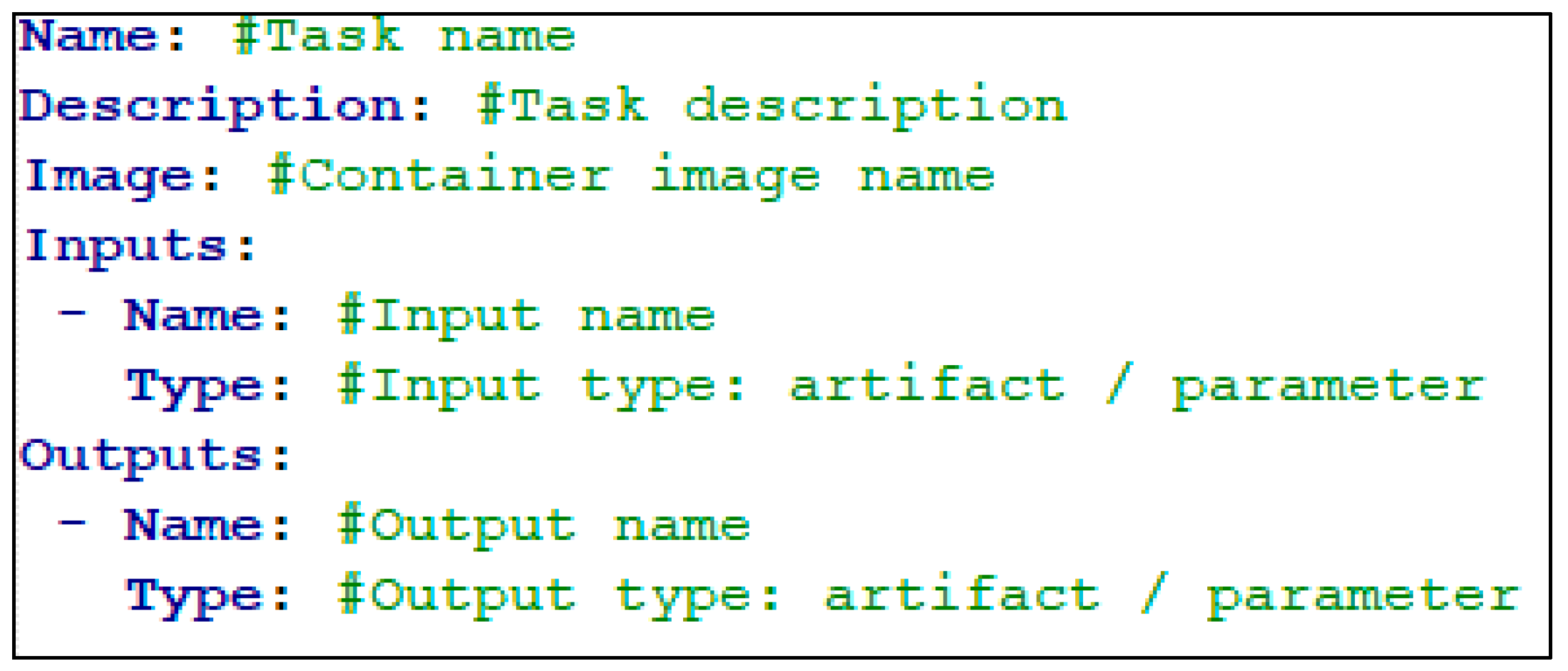
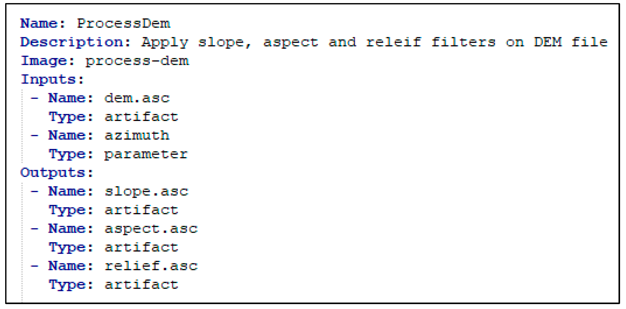
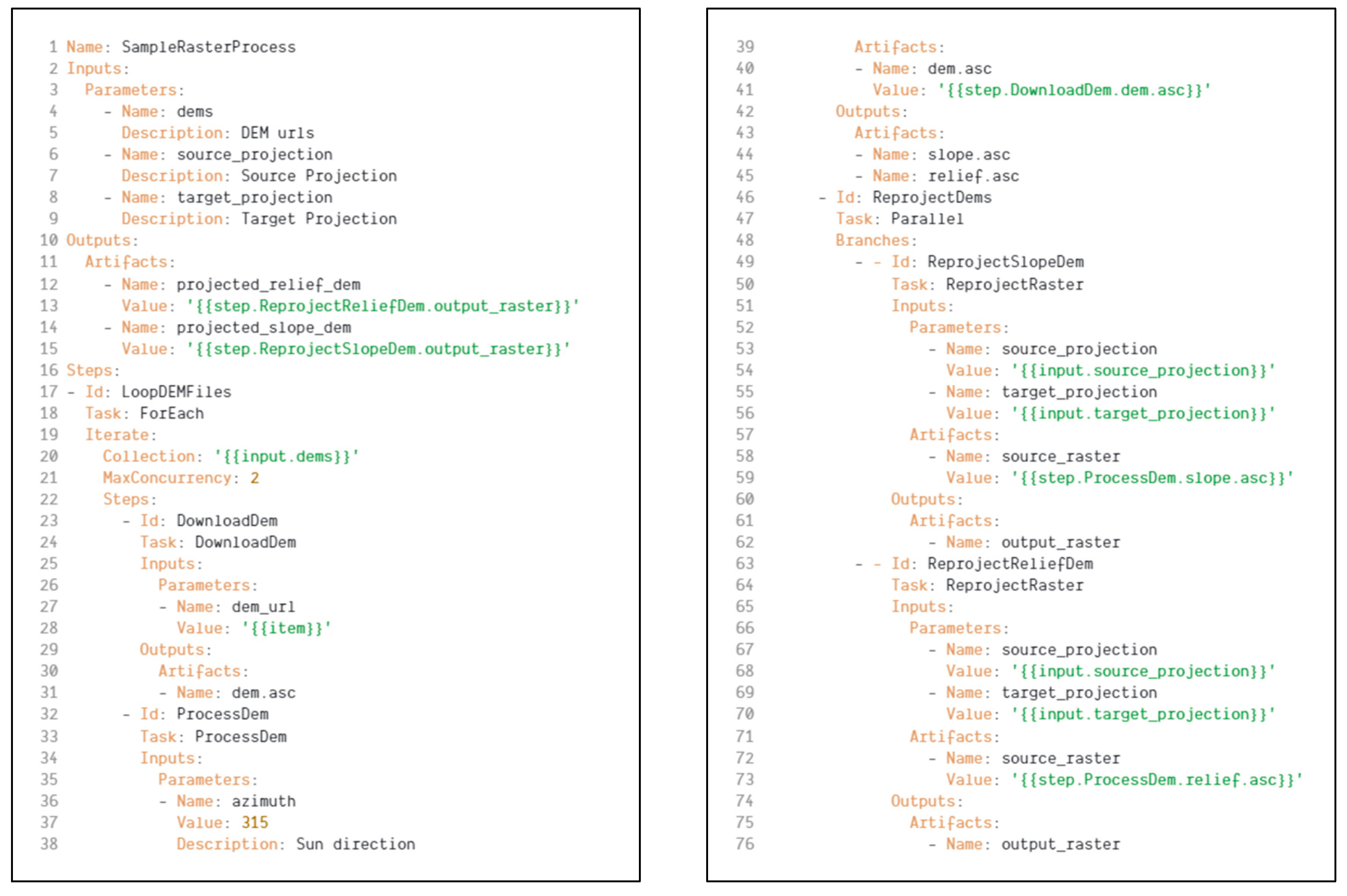
3.1.1. Task Definition

Task definition describes a new task that can be used as a step in a workflow to execute deployed application code in the container image (Figure 2). As the workflows are composed of different tasks, a task definition plays a vital role to add new capabilities to the system.
Task definition has a set of rules for each property to keep task definitions consistent It is also important to eliminate errors in task definitions before executing them.
Table 1 shows validation rules for each property in the definition. These rules are embedded into the workflow system and run before storing in the database and also executing them.
Inputs or outputs can be empty if there is no output or input for the task.
Parameter values are passed as a string to the associated container in runtime. The containerized application’s responsibility is to handle and cast the value to another type. Artifact refers to a binary data format, and they are passed as a file that is saved on the container’s file system in runtime.
Figure 3 shows an example task definition that uses a “process-dem” tagged container image to apply different filters on raster digital elevation model (DEM) files. We will use this example in the implementation section as a part of the sample workflow.

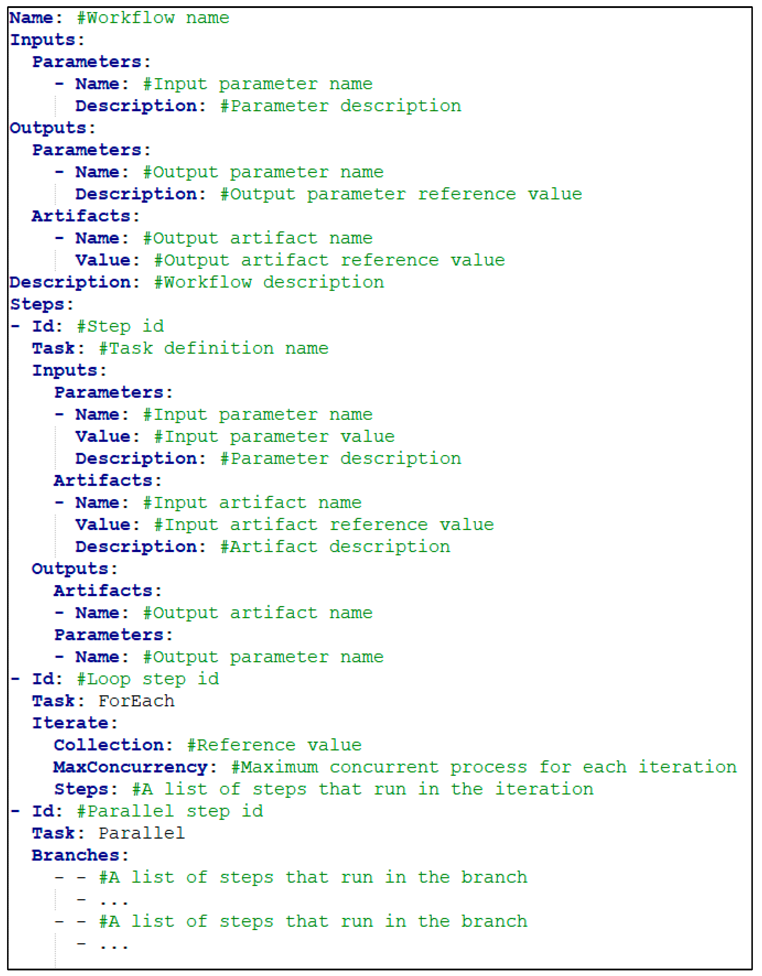
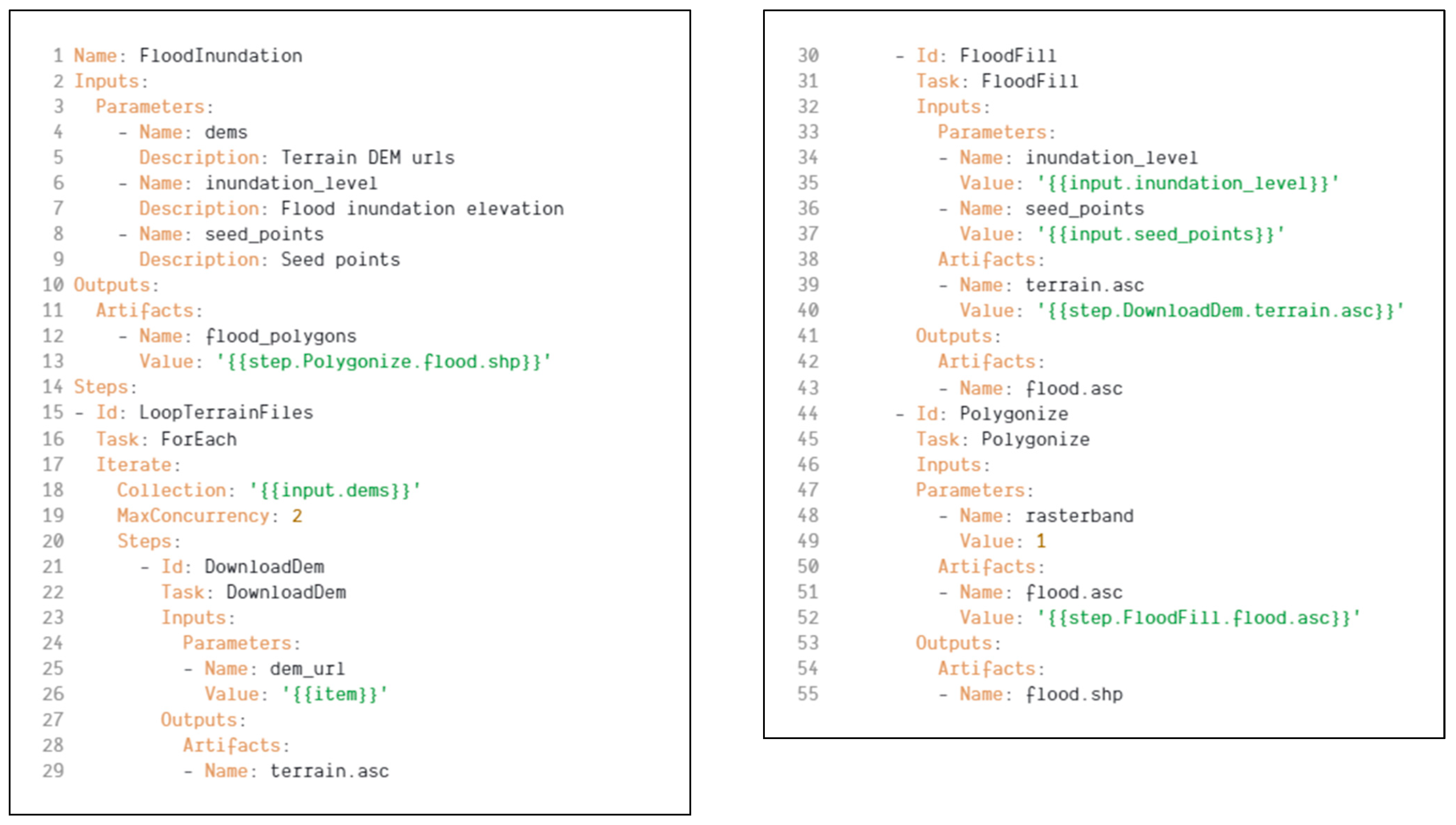
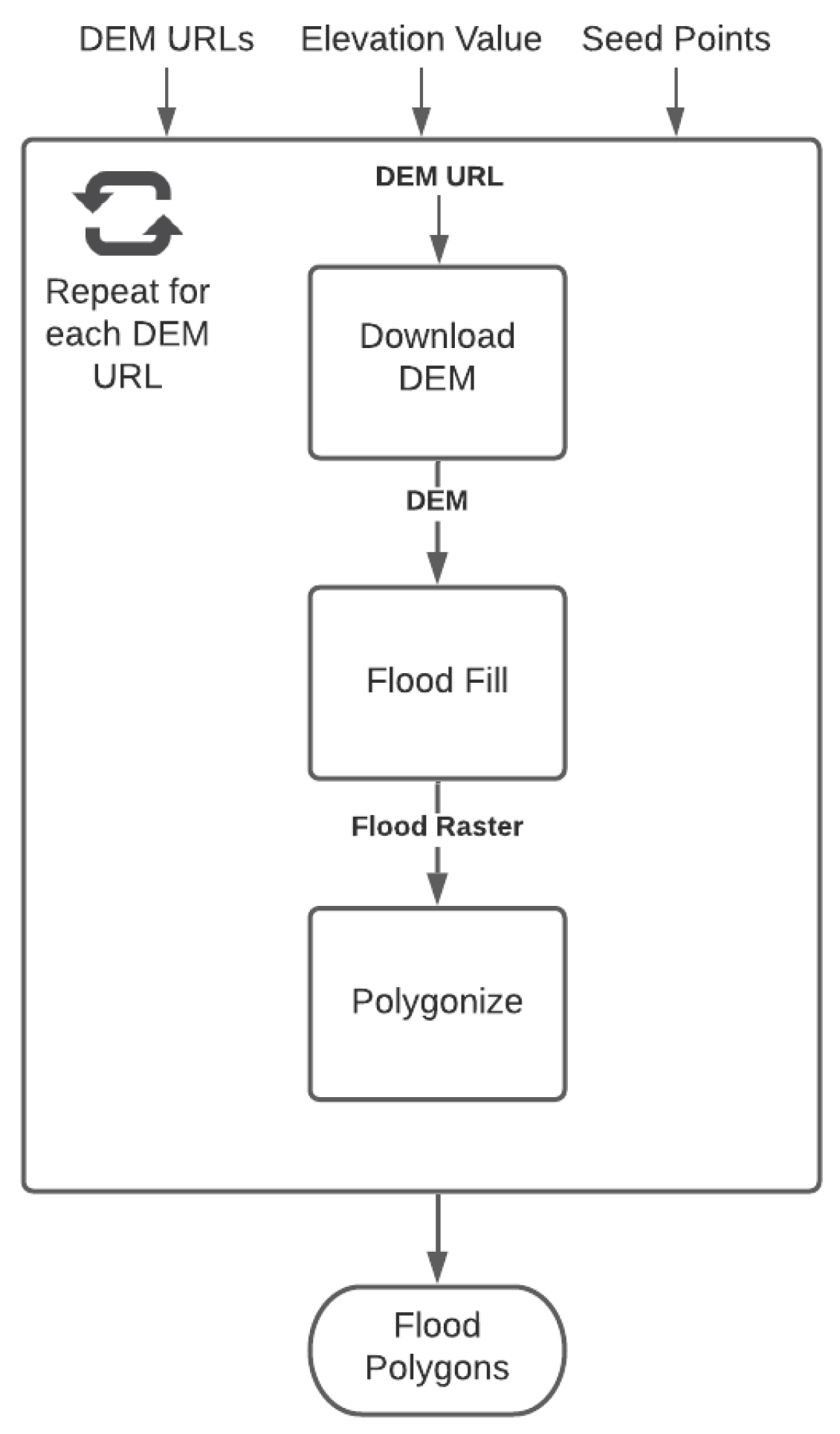
3.1.2. Workflow Definition

The workflow definition is the composition of different tasks run in a declared order (Figure 4). Once a workflow is validated and stored, it can be called as many times as desired to execute.
The proposed system supports sequential, parallel, and loop execution flows. In order to carry out these types of flows, the workflow definition can have abstract steps named “ForEach” and “Parallel” that are not linked to custom-built task definitions. The definition supports nested iterations and parallel flows, and for example, a parallel step can contain an iteration step, or an iteration branch can contain a parallel step.
Reference values are used to pass interim data generated by another step in the workflow execution. Reference values are helpful to carry data between steps.
These are possible reference values:
{{step.[StepId].[OutputName]}}
{{input.[InputName]}}
The reference value is formalized with a step output or input name, and step id must exist inside the same workflow definition. The steps inside an iteration step can also have a “{{item}}” reference value as an input; however, this value cannot address upper iteration scopes. Referenced values can only refer to previous steps.
Similar to the task definition model, our proposed workflow definition model also has a set of validation rules (Table 2). Once a workflow is validated and stored, it can be called as many times as desired to execute.
All description properties are optional and can be free text. Even though they are optional, it is recommended to populate description fields to generate user documentation and useful metadata information.
There is no defined limit on the number of parallel branches and maximum concurrency limit in the validation rules. On the other hand, system administrators could advise maximum limits based on the computational limits.

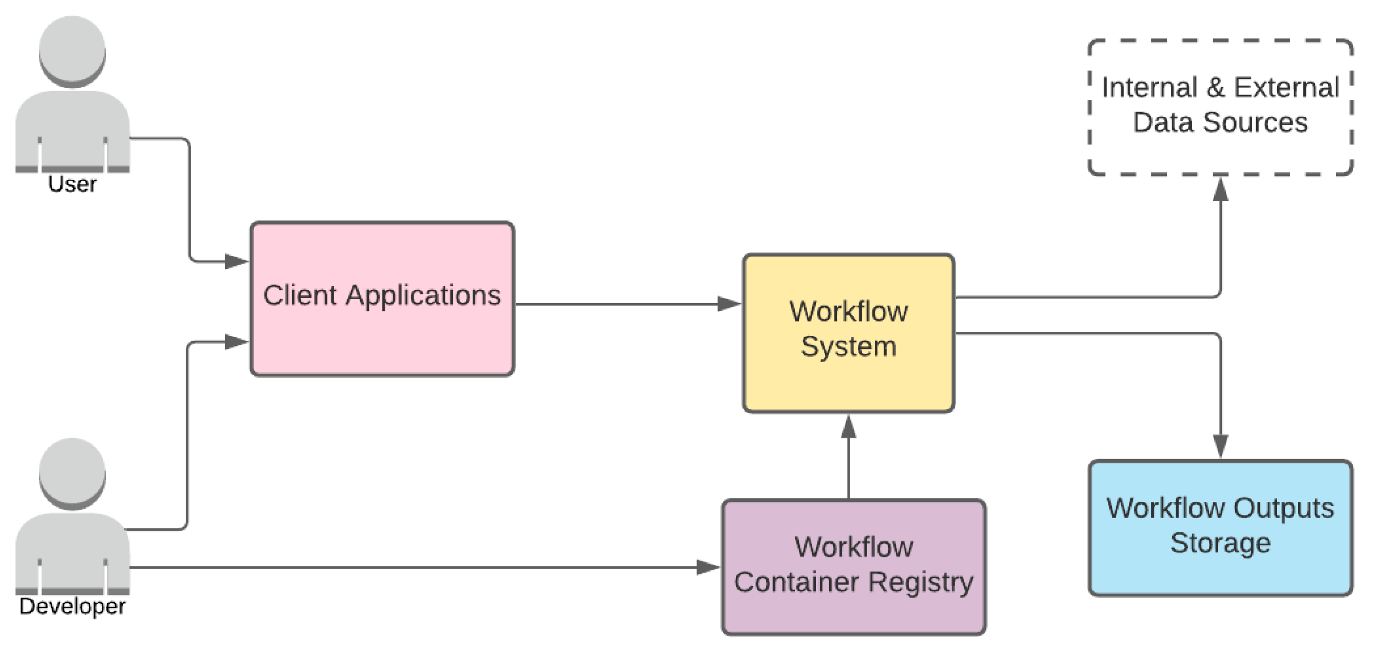
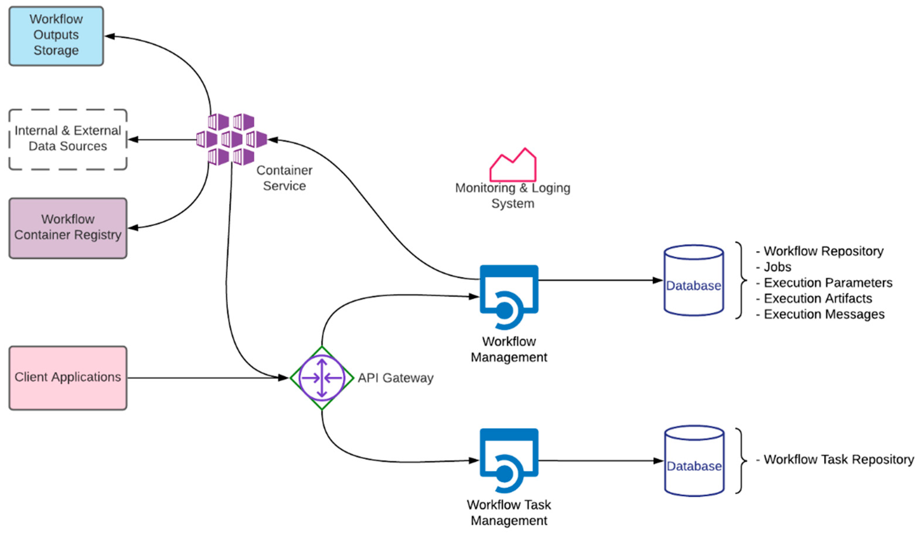
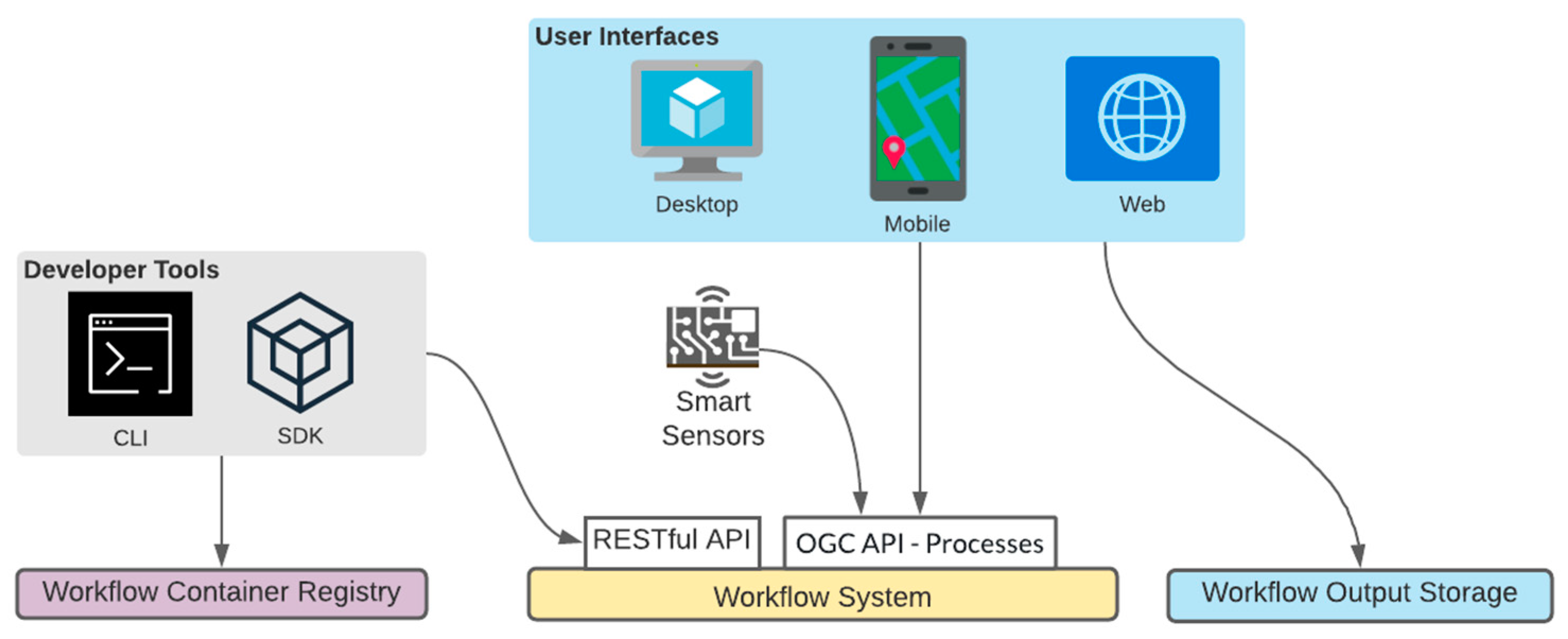
3.2. System Architecture

We aimed to keep the system architecture with minimum components to reduce complexity on deployment and management. This simple architecture can be easily deployed to any cloud provider or on-premises. On the other hand, it is easy to monitor and organize a simple architecture for a system administrator. Another advantage is that it allows developers to troubleshoot quickly and contribute new functionalities when needed. Moreover, we presume that a developer with basic knowledge of cloud technologies could set up our proposed system design on a public cloud provider or on-premise infrastructure.
The system architecture components should work based on demand and not consume any resources except for storage in the idle phase to achieve the serverless deployment goal. Communications between each system component should be completed through secured channels.
Figure 5 illustrates the high-level system architecture we examined with four different components and two roles. These components are:
  • Workflow System
  • Workflow Container Registry
  • Workflow Outputs Storage
  • Client Applications
We will explain each component in detail with supporting diagrams. Furthermore, the roles are;
  • User
  • Developer
In the next section, we will give details about these roles and explain their responsibilities. Then, the following sections will give details about components.

3.2.1. Roles

The proposed system has two different roles: developer and user.
Developer. The developer is responsible for monitoring, extending, and maintaining the system. This role should have access to monitoring and administration systems. In some instances, a system administrator can share monitoring and administration responsibilities. The developer develops the workflow tasks. The developer thus should be well trained on the workflow task development and have the necessary tools and skills to introduce a new workflow task to the system. As the system relies on containers and workflow tasks are coupled with container images, the developer should have access to push new container images to the container registry system. The developer is also responsible for creating documentation for each newly created workflow task. It must be considered that a workflow task documentation should give all necessary information about the workflow task to enable a user to use it in a workflow without any hassle. Since the system does not require managing cloud infrastructure as it can use the cloud provider’s APIs to control its container execution system, the developer does not need a comprehensive understanding of cloud infrastructure.
User. The user is responsible for designing a workflow with available workflow tasks in the task repository. The user should decide which data sources will be used in the workflow and assess whether they can be used with the selected workflow task. The user role and developer role may need to work collaboratively. For example, suppose a data source is incompatible with the workflow task. In that case, the user and the developer may need to join forces to modify the incompatible task or introduce a new one. The user should have access to published documentation to learn how to use the system and available workflow tasks.
The user should have enough insight to diagnose the problem in the failed workflow execution. If the problem is rooted in the workflow system components, the user should report it to developers. If a graphical user interface is provided to users for using a workflow system, the user should also be well trained on this interface.

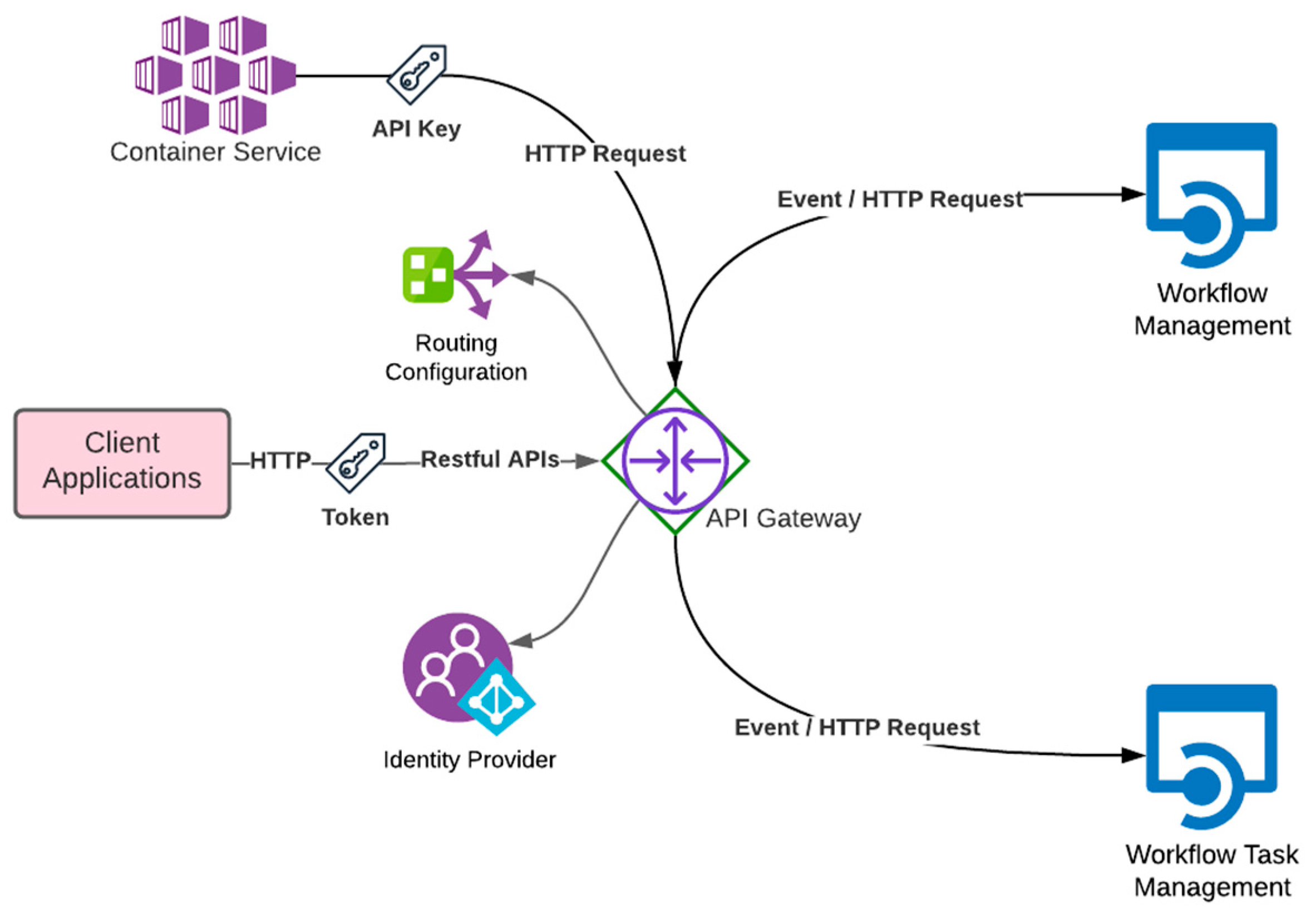
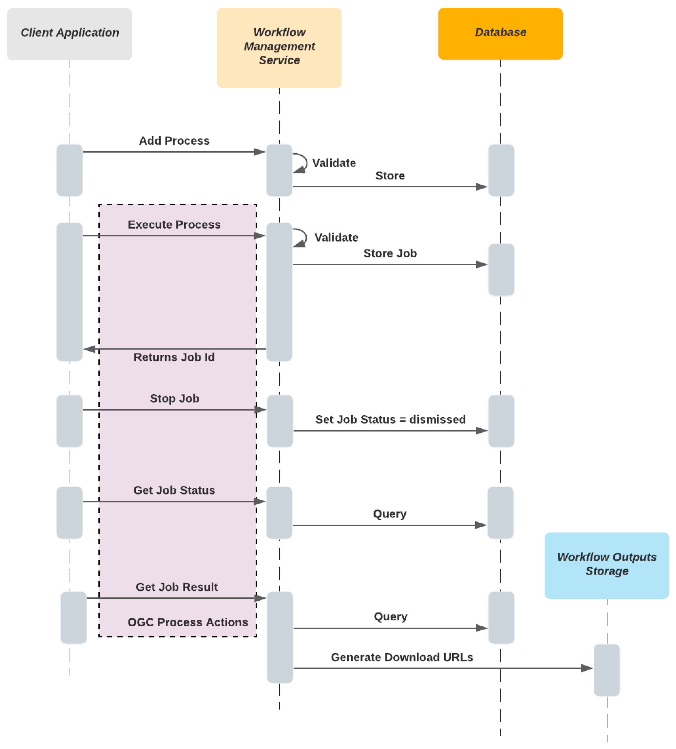
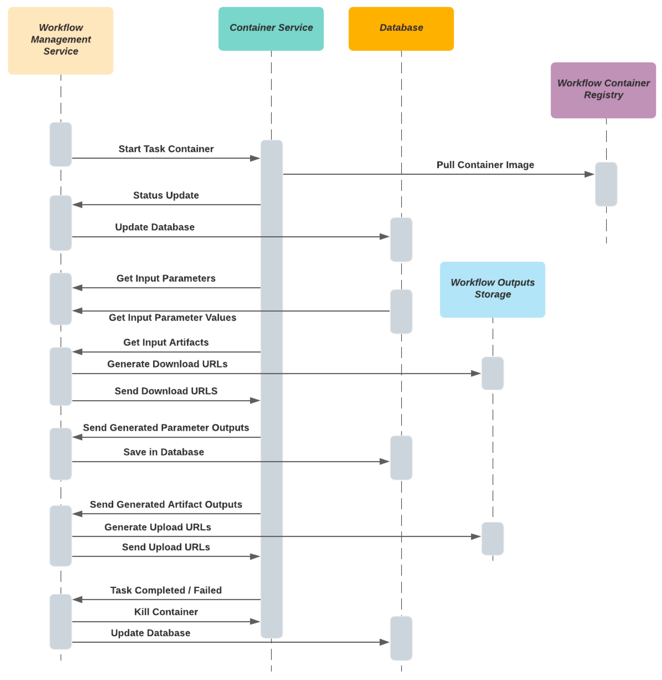
3.2.2. Workflow System

The core component of the high-level architecture is the workflow system that handles all user and container requests and generates a response or event.
Figure 6 shows that the workflow system consists of the following six child components that will be explained in detail consecutively in this section:
  • Workflow Management
  • API Gateway
  • Container Service
  • Workflow Task Management
  • Database
  • Monitoring and Logging System
We designed the system with components and technologies that can run on serverless technologies. In hybrid scenarios, some components such as container services can be selected either from a cloud provider services or deployed on-premises.
Workflow Management. The workflow management component is a backend service that provides Representational State Transfer (RESTful) API to run and track workflow executions. The workflow management service is responsible for carrying out the following operations:
  • Validate and store workflow definitions
  • Run, stop and monitor workflow executions
  • Present workflow execution deliverables such as literal and binary outputs
In our design, all workflow executions are considered long-running processes because they are highly coupled with other long-running processes such as container execution and pulling data from another data source. All workflow execution requests are handled with the asynchronous request-reply pattern. This pattern makes it possible to deploy the workflow management service on a stateless FaaS service with short execution times.
Figure 7 shows how client requests are executed in which order via a sequence flow. The OGC API Processes compliant actions are depicted in a purple shaded area.
The workflow management service is also responsible for validating workflow definitions before executing and storing them.
In addition to custom RESTful API endpoints, the workflow management service provides the OGC API Processes compliant endpoints to increase interoperability with other geospatial desktop and mobile applications. OGC API Processes is the new version of the OGC Web Processing Service (WPS) specification, and it defines geoprocessing service standards [22]. The new specification version is built concerning modern web development practices that ease integration with the new system architectures. Each stored workflow definition can be retrieved as an OGC Process, and workflow names are represented as `Process Id` in the OGC responses. All stored workflows can only be executed asynchronously, so the synchronous execution option should not be offered.
Execution results are generated using parameter and artifact outputs from completed execution. The workflow manager service calls the workflow outputs storage API to generate temporary signed download Uniform Resource Locators (URL) if artifact outputs are generated. So, the client application can download them without keeping the workflow management service instance busy.
The workflow management service is also responsible for executing workflows by interacting with other components (Figure 8). We designed it to be deployed with the FaaS model. Thus, it is a stateless service and uses the database to store all workflow execution states. It provides RESTful APIs to handle HTTP requests from containers to update execution and job status and proceed to the subsequent step in the workflow. The API Gateway routes all HTTP requests from containers to the workflow management service.
The workflow management service should know how to interact with the container service to create, run, and kill containers based on the execution step’s requirements. Therefore, the container service should be accessible to the workflow orchestrator via APIs.
During task execution, the service should generate temporary upload and download signed URLs from workflow output storage for inputs and outputs artifacts and send these URLs to the caller container securely upload or download files. It is crucial to generate temporary URLs with enough time to upload and download large files without interruption.
The workflow management service should set the required environment variables to run containers. For example, the API Key needs to be injected as an environment parameter into the container to communicate with the workflow orchestrator securely.
API Gateway. The API gateway sits between the client applications and two management services, and it routes HTTP traffic to a relevant backend service based on the routing configuration (Table 3). The API gateway should also translate HTTP requests into FaaS events to invoke FaaS backend services [23]. It is essential because all management services are designed to deploy as a FaaS when it is possible.
The API Gateway should be selected as a managed and serverless service in public cloud providers to reduce management and increase scalability.
The API Gateway should support creating RESTful APIs and JSON payload support in HTTP requests and responses.
Another role of API Gateway is to protect management services from unauthorized requests [24]. It should support token-based authentication (Figure 9). In our proposed design, backend services delegate authentication and authorization to the API Gateway. Thus, the API gateway should have identity provider integration support to leverage a user store and authorize requests with an access control list (ACL). In that way, backend services are simplified from extra security layers. In addition, the API gateway should support or allow the machine-to-machine communication that is needed for securing the HTTP calls between workflow management and container service.
Container Service. The container service is the core computation element of the workflow system, and it is responsible for running requested container images to execute custom-built code with inputs. In our design, we proposed to use a CaaS based platform as a container service in a public cloud provider. These platforms abstract complex operational requirements and enable users to scale and manage the system quickly [25].
In the implementation, containers may need to access external or internal data sources to process. In addition, containers need to make HTTP calls to the workflow manager to report their status and pull the required information to run. In such circumstances, the container service should allow containers to access external internet sources and the workflow manager through the API Gateway component.
The container service should also have an API that integrates the workflow management service to manage the container lifecycle. For instance, the workflow management service needs to spin up or terminate containers based on the task execution status, so an API should provide these procedures.
Workflow Task Manager. The workflow task management component is another backend service that provides a RESTful API to manage workflow tasks, and it is designed to be used by the developer role mainly. The workflow task management service is responsible for validating and storing workflow task definitions. The service could need to call the container registry to check whether the associated container image tag exists or not in the scope of the validation process.
The workflow task manager service should also expose the API documentation based on the Open API Specification (OAS) that is widely supported to allow the developer to learn endpoints or make it possible to create a software development kit (SDK) or command-line interface (CLI) tool to interact with the API [26].
The service uses the database to store task definitions in proposed task definition models.
Database. The proposed design does not have any mandatory criteria for database selection. Nevertheless, the database should be selected as managed and serverless service in public cloud providers to reduce management and increase resource optimization. Designated database technology should have indexing features to improve query performance. In addition, it should have sufficient support for the programming languages used in backend services development.
The database entity models should be designed concerning OGC Processing API specifications to return Processing API compliant responses via the workflow management service.
Another essential point is to consider that each backend service should have its private database or database table [27].
Monitoring and Logging System. Tracking system metrics and logs emitted from the system components is crucial for management and monitoring [28]. Developer and user roles should have access to the monitoring and logging component. The user should only have read-only access and create alarms based on the metrics or logs. The developer can configure metrics and design a monitoring dashboard to see the big picture. The developer can also add new data sources to ingest more logs and metrics from the other infrastructure components.
The system should have the necessary APIs and SDKs for the programming languages used by backend services. Moreover, it should support integrating selected services to collect enough metrics and logs.

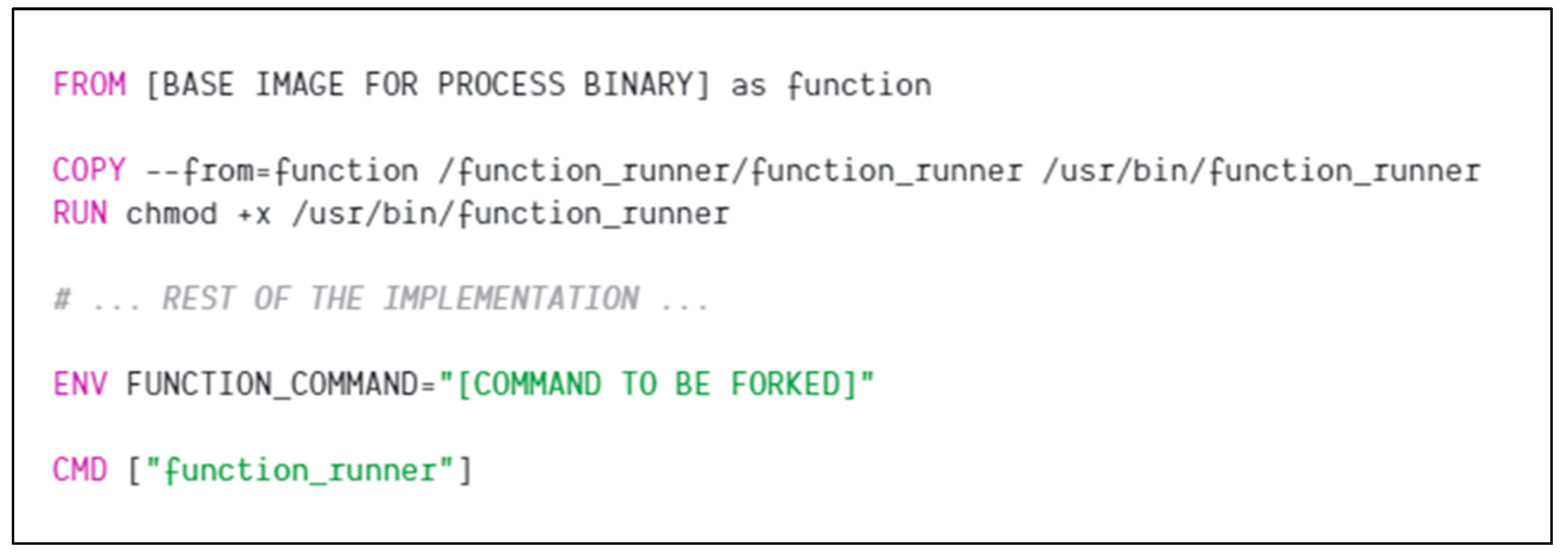
3.2.3. Workflow Container Registry

In this component, container images built by the developer are stored. When the workflow step is needed to be executed, the container service pulls the stored container image from the workflow container registry based on the container image name (Figure 8). The container image name value is obtained from the related workflow task definition.
These container images should be built with a caller agent. This caller agent is responsible for contacting the workflow management service via HTTP requests. When a process is started or completed, the agent should download and upload inputs and outputs. Fundamentally, this caller agent runs the given command in a child process and collects its console outputs and errors. It can report all these console logs and errors to the workflow orchestrator for logging. It can also obtain the return code from the child process. Thus it can report when the process is completed with success or an error.
The caller agent can be embedded into a base container image in our proposed solution to increase reusability. A container image can be inherited from another container image to extend its functionality. Thus, container images for task executions can be inherited from this base container image, as shown in Figure 10. Another critical point is that the caller application should have a retry mechanism to keep the container alive in case of short outages in the workflow management system or API gateway [29].

3.2.4. Workflow Output Storage

The workflow step executions need a storage component to save output artifact objects. In public cloud providers, storage systems are called object storage, and object storages manage binaries as objects, unlike file systems [30]. There are also open-source object storage technologies that can be used in on-premise deployment [31]. We recommend using object storage service in both deployment scenarios to enable secure, scalable and accessible object management through HTTP requests.
The workflow output storage should be selected as an object storage service. This type of storage service enables object management and access via APIs. As we explained in previous sections, the workflow system should be accessible by the caller agents in containers and the workflow management service. They should be compatible with the workflow output storage APIs.
This storage should allow saving these artifact objects in a structure. Objects are stored as partitioned by job id and step id as follows; “{job-id}/{step-id}/{iteration- id}/output -name”. In this structure, “{iteration- id}” is zero by default, while iteration step outputs are stored with an incremental iteration index number.
The workflow output storage API should have endpoints to generate temporary URLs for stored objects, accessing objects securely via different components or roles.

3.2.5. Client Applications

The client applications can be grouped into two categories. The first category can be called “User Interfaces”, which are different types of applications that target the user role. The second category can be called “Developer Tools”, which are applications and SDKs used by the developer role (Figure 11). All client applications perform API calls with token-based authentication against the workflow system.
User interfaces are applications with a graphical user interface that provide an easy and intuitive way to interact with the APIs provided by the proposed system architecture. They can be run on desktop, mobile and web platforms. The user interface applications also need to access workflow output storage to download generated outputs with temporary URLs.
Developer tools could help build user interfaces, register new workflow task definitions, and publish new container images. When the selected containerization technologies provide tools, they can be used to build and publish container images by the developer [32].

4. Implementation

To evaluate the proposed system architecture, we first implemented it in one of the commonly used and mature public cloud providers as a proof of concept. The AWS cloud provider was selected because it has various serverless services that we can leverage to deploy a complete serverless system. The other public cloud providers have similar services that can also be used for deployment. Another reason to select AWS is that it offers a Well-Architected framework to review whether cloud architectures follow architectural best practices [33]. Therefore, we examined the proposed system architecture over the proof of concept in the evaluation section with this framework’s pillars.

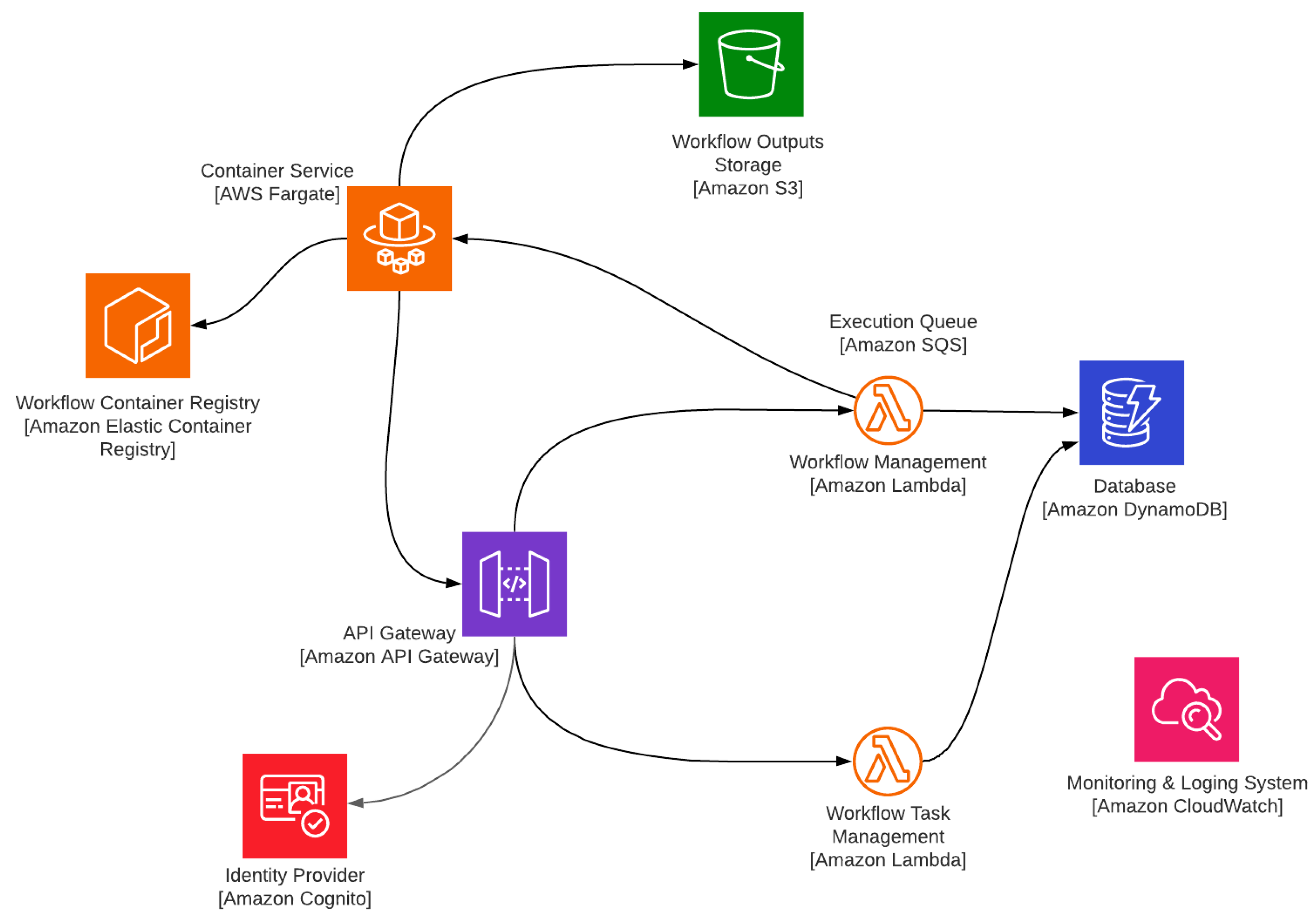
4.1. Cloud Implementation

This section examines the deployment of the proposed system architecture with AWS as a public cloud provider. We designed our system architecture that can be deployed as serverless, so we preferred the cloud provider’s only serverless services for each component to demonstrate its applicability with serverless deployment. Figure 12 illustrates the system implementation diagram with AWS service names and component names in the system architecture section. We explain each component deployment and implementation by giving details of the selected service and programming language.

4.1.1. Used Services in Amazon Web Service

All AWS services provide APIs enable integration with other services and deployed applications. The communication between AWS services is seamlessly established securely. In addition, AWS supports various Infrastructure-as-a-Code (IaaC) deployment models that enable infrastructure management with machine-readable descriptive models [34]. This deployment model makes it easier to keep infrastructure in a versioning system. Another common point of all selected services is integrating with a central monitoring and logging service named Amazon CloudWatch. This service gives valuable insight into problems and resource utilization [35].
Amazon S3 service was selected to use as workflow outputs storge. It manages object storage and supports organizing objects by using prefixes. Furthermore, it is also possible to generate temporary URLs for downloading and uploading objects [36].
Amazon API Gateway is the only API gateway solution in the AWS service portfolio, so we placed it for the API gateway component. We configured it to route traffic to backend services based on path mappings. When used with Amazon Lambda, it can route HTTP requests to Amazon Lambda function as events [37]. It also supports token-based authorization to protect APIs from unauthorized access.
We used Amazon Cognito as an identity provider to authorize requests based on the access control list with proposed user and developer roles. Amazon Cognito is also an authentication provider that can handle user sign-in.
Amazon Lambda was used to deploy all backend services in our design. It is an event-driven FaaS based service, and it supports a wide range of programming languages and is triggered by events originating from other AWS services [38]. It has explicitly built-in integration with Amazon API Gateway.
Amazon DynamoDB is a document-based key-value database, so it brings an approach to database modelling different from traditional relational databases [39]. Amazon DynamoDB was used as a database component to store all entities. We used the on-demand type of provisioning. Our design supports OGC API Processes, so we honored the specification in the data modelling. An alternative serverless database service option could be Amazon Aurora Serverless. It could be preferred when there is a need to construct a more complex and relational database since it is based on PostgreSQL relational database server with geospatial data support [40].
Amazon Container Registry is another fully-managed service that supports storing, managing, and deploying Docker container images. It is used as the container registry component to store container images associated with workflow tasks.
Amazon Fargate is a relatively new AWS service that gradually replaces the older EC2 Container Service (ECS) for production and sandbox workloads [41]. It is offered with a serverless CaaS model and supports running Docker containers on-demand or on schedule. We configured Amazon Fargate to run workflow task containers with internet and workflow storage account access. Thus, containers can access internal and external data sources during runtime.

4.1.2. Backend Development
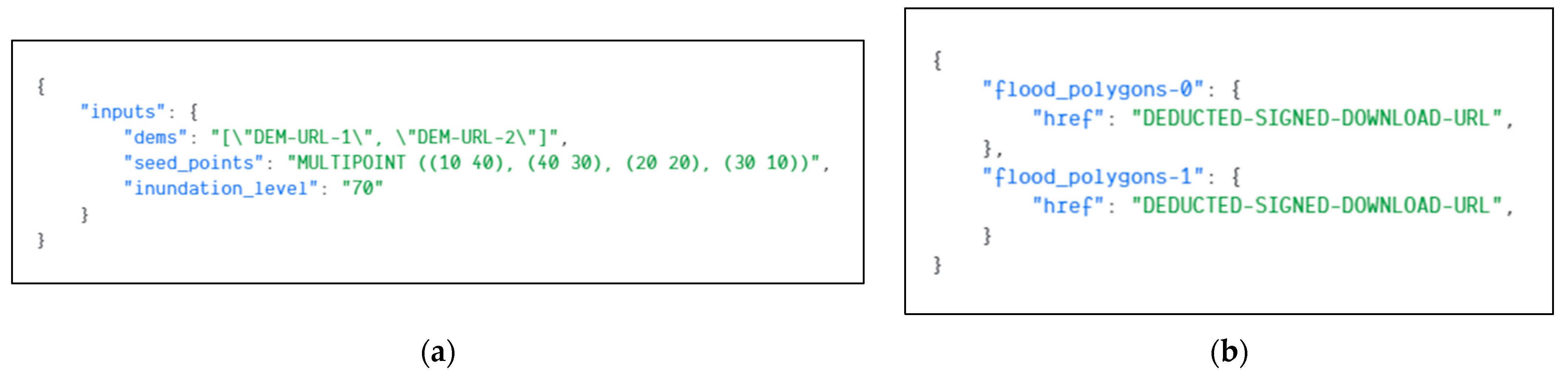
We developed two backend services designed as microservices. Each service can be deployed and scaled separately. As we deployed them on Amazon Lambda, scaling and availability are managed by AWS. We used the .Net Core Framework version 3.1 with C# programming language to develop all components. We followed and applied Adam Wiggins’s twelve-factor app methodology in the development [42].
Backend services were created with the .Net Core Web API framework that allows creating RESTful APIs with built-in support for the JSON format. Since we designed our workflow and task definition models in the YAML format, we added a library to parse YAML requests to accept workflow and task definitions. In addition, we used other open-source libraries to implement additional requirements. For example, we used the MediatR library to implement Command Query Responsibility Segregation (CQRS), an architectural pattern that separates the commands and the queries by two different methods of communication [43]. CQRS is commonly used for systems that handle complex interactions with multiple changing data sources across process boundaries. Besides these libraries, AWS .Net libraries are also used to securely interact with the Amazon Fargate, Amazon S3 and Amazon DynamoDB APIs [44].
The container agent was compiled as executable for Linux environments. The .Net Core framework supports compiling self-executable files for the Linux operating system. This is crucial because the Docker images that we used in the evaluation are Linux based.

4.2. Evaluation

For the sake of brevity, we evaluated the system with two inclusive sample workflows that leveraged all presented features in workflow definition models and challenged the system design over execution models such as parallel and iterative processing. Therefore, we demonstrated how our workflow definition model could define complex geospatial processes with the proposed serverless system. In addition, we reviewed the proposed architecture with AWS Well-Architected tool that describes the key concepts, design principles, and architectural best practices for designing and running workloads in the cloud [33].
As a first example, we defined a sample workflow to process digital elevation models (DEM) downloaded from a public source and perform slope and relief raster calculations on each file together with coordinate system reprojection. The demonstrated sample is challenging for serverless data processing flows because computational requirements could not be handled in the FaaS model. We specifically preferred raster processing to show that the proposed system is applicable for long-running executions requiring more computation power and memory. Moreover, the sample workflow includes our proposed parallel and iterative execution tasks to demonstrate “ForEach” and “Parallel” tasks usages. Figure 13 illustrate the sample workflow that uses “ForEach” task to iterate a set of tasks to download DEM files and applies raster functions iteratively. When all iterations are completed, the next step reprojects DEM files to another coordinate system in parallel to demonstrate “Parallel” task and produce outputs.
To handle this workflow, we developed three different task definitions and docker container images to be used in the workflow (Figure 14). We used open-source geospatial Python libraries for these tasks.
Figure 15 shows example input parameters to execute and retrieved output parameters at the end of the execution of the sample workflow defined above. The request payload and the response body are in JSON format that complies with the OGC API Processes specification.
For a real-world example, we considered the flood inundation model. It is one of the most common geospatial analyses that visualize the impact of flooding on public infrastructure, critical facilities, and vulnerable populations. We used the flood inundation workflow developed by Joel Lawhead [45]. Briefly, this model starts with a seed point and floods an area with an inundation level. The flooded area is generated as a vector polygon for each terrain area. Figure 16 shows the workflow definition defined in the proposed workflow definition model.
We defined the workflow with a composition of three steps (Figure 17). The first step uses “ForEach” iteration task that loops the DEM URLs and runs the steps that perform the flood analysis for each downloaded DEM file.
Similarly, we also dockerized the flood prediction code and defined and registered the workflow tasks via Workflow Task Management API. We reused the “Download DEM” task from the previous sample to download terrain models
Figure 18 illustrates an example request payload containing input parameters to execute the flood workflow. In addition, an example response body has deducted URLs for representing signed download URLs of flood areas in vector format. The seed points are passed in the Well-known text (WKT) MultiPoint format, and the flood analysis calculation is executed for each intersected point in the terrain area.
We examined the implemented serverless cloud architecture with AWS Well-Architectured tools with its five pillars, and they are helpful to produce stable and efficient systems. AWS claims that these pillars help architects build secure, high-performing, resilient, and efficient infrastructure.
Pillar 1: Operational Excellence—We adopted the principles of this pillar. Infrastructure and code deployment can be automated in our design. In the implementation, we also automated code and infrastructure deployment with continuous integration and deployment tools and AWS cloud development kit. API deployments, workflow, and task deployments can be historically versioned and reversible in case of any failure in the deployment. We also refined user roles and procedural responsibilities in the System Architecture section. We tested the proposed system with different scenarios to increase its stability and reduce failures. For example, we presented two inclusive examples to challenge the system design in this paper.
Pillar 2: Security—This pillar focuses on protecting data and systems. As it suggests, we defined the roles with different privileges and put security first while designing the system. The API gateway component protects all backend endpoints with centralized identity management, and all data transmission between components uses secure channels. Workflow outputs are stored in private storage and can only be accessed by the workflow manager. Public URLs of the requested files are generated with a short lifetime and unique parameters.
Pillar 3: Reliability—The reliability pillar ensures that the system performs the intended function correctly and consistently when needed. We designed the system with serverless technologies, and this approach maximizes reliability as it brings scalability and availability. Thus, the system does not require a workload assessment as we used fully managed services. Unit and end-to-end tests in production-level implementations are needed to spot failures after each code change in the evaluation phase.
Pillar 4: Performance Efficiency—The performance efficiency pillar recommends using computing resources efficiently to meet requirements and maintain efficiency as demand changes. We proposed a serverless design and avoided using any continuously running service. Serverless architectures, by default, increase performance efficiency as much as possible by utilizing infrastructure resources in an optimum way. The proposed system design performance depends on the implementation and cloud infrastructure performance. For instance, container initialization adds latency for each step execution. This latency duration could differ between different container services for the CaaS model.
Pillar 5: Cost Optimization—The pillar of cost optimization focuses on eliminating unnecessary expenditures. Even though our primary focus on this paper is not to offer a cost-optimized system, serverless architectures are also cost-efficient by default. They use resources on-demand and usually do not cost when idle in public cloud providers. Once the system is deployed, it should be monitored continuously, and it may require limiting resource consumption to keep costs under control. On the other hand, serverless services abstracted infrastructure management and scalability automation from the user; thus, the proposed system design does not require an allocated system administrator who knows depth knowledge in cloud infrastructure management. The proposed developer role can handle necessary tasks for system management.

5. Discussion and Conclusions

Designing a geospatial workflow management system with minimum human intervention is still an issue in the geospatial community. We presented a study that can offer a solution to this phenomenon. We aimed to provide a system design that can be applied in real-world scenarios on any major cloud provider or on-premises that offers serverless technologies. The serverless technologies bring many new possible solutions for existing debating problems in data processing and application deployments.
The geospatial community is working on the area with different research types that require workflow to execute state of the art algorithms. They are actively developing new specifications to standardize and increase interoperability, and the OGC is one of the most well-known organizations that work on these specifications. They have been working on the WPS specification, and the last version is 2.0 [46]. On the other hand, they have also initiated a new set of specifications to replace existing standards with modern web development approaches. The WPS is to be replaced with a new name is OGC API Processes. Even though OGC API Processes is still in draft and open to breaking changes, we preferred to use this standard to review and examine it with serverless technologies. We found that the new standard has a steep learning curve compared to the previous version, and we could easily add endpoints that respond in the standard’s format and rules. We aimed to increase awareness of serverless technologies in the geospatial community by exploring a geospatial data processing workflow on the serverless model with the OGC API Processes.
We observed that Amazon Fargate service is a bit complex to run one-off containers than other providers. For example, Microsoft Azure provides Container Instances service with much fewer configuration requirements. On the other hand, Amazon Cloud Deployment Kit (CDK) made it easier to deploy cloud infrastructures in the same programming language we used for development. We observed that the system also works as expected with hybrid scenarios. We ran the system with a local container service. The only problem with the hybrid system is that the network speed is throttling the speed of executions because the containers download and upload the data through the internet.
In the implementation, we used the CaaS service for executing tasks because they are more capable and less restrictive to run long-running data processing tasks. We think that FaaS could also be used for running these types of tasks in the future. As we have seen the container image deployment support in some public cloud providers’ FaaS services, we think it could be possible soon.
In our design, the communication from workflow manager to task manager is synchronous, and we think adding messaging queue can increase reliability and fault-tolerance in the design. However, we thought it could also increase complexity, and the failures could be mitigated with other design patterns such as the circuit breaker or retry.
This study also presented a new workflow and task definition model. Moreover, the workflow model has two custom-built tasks: “ForEach” and “Parallel”. These help run iterative and concurrent operations. We are also planning to add control statements to change the direction of the flow during the runtime.
We designed the system within the geospatial context, but it can be applied to other data processing workflows. We plan to publish the source code of proof-of-concept as an open-source project once the code documentation is completed.

Author Contributions

Conceptualization, Mete Ercan Pakdil and Rahmi Nurhan Çelik; methodology, Mete Ercan Pakdil; software, Mete Ercan Pakdil; validation, Mete Ercan Pakdil and Rahmi Nurhan Çelik; writing—original draft preparation, Mete Ercan Pakdil; writing—review and editing, Rahmi Nurhan Çelik; supervision, Rahmi Nurhan Çelik. All authors have read and agreed to the published version of the manuscript.

Funding

This research received no external funding.

Data Availability Statement

No new data were created or analyzed in this study. Data sharing is not applicable to this article.

Acknowledgments

We acknowledge colleagues from Mott MacDonald Digital Ventures for their support and encouragement.

Conflicts of Interest

The authors declare no conflict of interest.

References

  1. de Oliveira, D.; Ogasawara, E.; Baião, F.; Mattoso, M. SciCumulus: A Lightweight Cloud Middleware to Explore Many Task Computing Paradigm in Scientific Workflows. In Proceedings of the 2010 IEEE 3rd International Conference on Cloud Computing, Miami, FL, USA, 5–10 July 2010; pp. 378–385. [Google Scholar]
  2. Mell, P.M.; Grance, T. The NIST Definition of Cloud Computing. NIST 2011, SP 800-145, 2–3. [Google Scholar]
  3. Lloyd, W.; Ramesh, S.; Chinthalapati, S.; Ly, L.; Pallickara, S. Serverless Computing: An Investigation of Factors Influencing Microservice Performance. In Proceedings of the 2018 IEEE International Conference on Cloud Engineering, Orlando, FL, USA, 17–20 April 2018; pp. 159–169. [Google Scholar]
  4. Rahman, M.M.; Hasan, M.H. Serverless Architecture for Big Data Analytics. In Proceedings of the 2019 Global Conference for Advancement in Technology, Bangaluru, India, 18–20 October 2019; pp. 1–5. [Google Scholar]
  5. Krämer, M. A Microservice Architecture for the Processing of Large Geospatial Data in the Cloud. Ph.D. Thesis, Technische Universität Darmstadt, Darmstadt, Germany, 2018. [Google Scholar]
  6. Agarwal, G. Modern DevOps Practices; Packt: Birmingham, UK, 2021. [Google Scholar]
  7. Baldini, I.; Castro, P.; Chang, K.; Cheng, P.; Fink, S.; Ishakian, V.; Mitchell, N.; Muthusamy, V.; Rabbah, R.; Slominski, A.; et al. Serverless Computing: Current Trends and Open Problems. In Research Advances in Cloud Computing; Chaudhary, S., Somani, G., Buyya, R., Eds.; Springer: Singapore, 2017; pp. 1–20. [Google Scholar]
  8. Kim, Y.; Lin, J. Serverless Data Analytics with Flint. In Proceedings of the 2018 IEEE 11th International Conference on Cloud Computing, San Francisco, CA, USA, 2–7 July 2018; pp. 451–455. [Google Scholar]
  9. Malawski, M.; Gajek, A.; Zima, A.; Balis, B.; Figiela, K. Serverless Execution of Scientific Workflows: Experiments with HyperFlow, AWS Lambda and Google Cloud Functions. Future Gen. Comput. Sys. 2020, 110, 502–514. [Google Scholar] [CrossRef]
  10. Lee, H.; Satyam, K.; Fox, G. Evaluation of Production Serverless Computing Environments. In Proceedings of the IEEE 11th International Conference on Cloud Computing, San Francisco, CA, USA, 2–7 July 2018; pp. 442–450. [Google Scholar]
  11. Ji, X.; Chen, B.; Huang, Z.; Sui, Z.; Fang, Y. On the Use of Cloud Computing for Geospatial Workflow Applications. In Proceedings of the IEEE 20th International Conference on Geoinformatics, Hong Kong, China, 15–17 June 2012; pp. 1–6. [Google Scholar]
  12. Krämer, M.; Würz, H.M.; Altenhofen, C. Executing Cyclic Scientific Workflows in the Cloud. J. Cloud Comp. 2021, 10, 25. [Google Scholar] [CrossRef]
  13. Serverless Workflow. Available online: https://serverlessworkflow.io/ (accessed on 23 October 2021).
  14. AWS Step Functions. Available online: https://aws.amazon.com/step-functions (accessed on 23 October 2021).
  15. Azure Logic Apps documentation. Available online: https://docs.microsoft.com/en-us/azure/logic-apps/ (accessed on 23 October 2021).
  16. Google Cloud Workflows. Available online: https://cloud.google.com/workflows (accessed on 23 October 2021).
  17. Huang, W.; Zhang, W.; Zhang, D.; Meng, L. Elastic Spatial Query Processing in OpenStack Cloud Computing Environment for Time-Constraint Data Analysis. ISPRS Int. J. Geo-Inf. 2017, 6, 84. [Google Scholar] [CrossRef] [Green Version]
  18. Argo Workflows. Available online: https://argoproj.github.io/argo-workflows/ (accessed on 23 October 2021).
  19. Kubeflow. Available online: https://www.kubeflow.org/ (accessed on 23 October 2021).
  20. van der Aalst, W.M.P.; ter Hofstede, A.H.M. YAWL: Yet Another Workflow Language. Info. Sys. 2005, 30, 245–275. [Google Scholar] [CrossRef] [Green Version]
  21. YAML Ain’t Markup Language. Available online: https://yaml.org/ (accessed on 23 October 2021).
  22. Pross, B.; Vretanos, P.A. OGC API—Processes—Part 1: Core, 1.0-Draft.7; Open Geospatial Consortium: Arlington, VA, USA, 2021; Available online: https://docs.ogc.org/is/18-062r2/18-062r2.html (accessed on 23 October 2021).
  23. Taibi, D.; Spillner, J.; Wawruch, K. Serverless Computing-Where Are We Now, and Where Are We Heading? IEEE Softw. 2021, 38, 25–31. [Google Scholar] [CrossRef]
  24. Taibi, D.; Lenarduzzi, V. On the Definition of Microservice Bad Smells. IEEE Softw. 2018, 35, 56–62. [Google Scholar] [CrossRef]
  25. Ingeno, J. Software Architect’s Handbook; Packt: Birmingham, UK, 2018. [Google Scholar]
  26. Karavisileiou, A.; Mainas, N.; Petrakis, E.G.M. Ontology for OpenAPI REST Services Descriptions. In Proceedings of the IEEE 32nd International Conference on Tools with Artificial Intelligence, Baltimore, MD, USA, 9–11 November 2020; pp. 35–40. [Google Scholar]
  27. Messina, A.; Rizzo, R.; Storniolo, P.; Urso, A. A Simplified Database Pattern for the Microservice Architecture. In Proceedings of the 8th International Conference on Advances in Databases, Knowledge and Data Applications, Lisbon, Portugal, 2–4 June 2016; pp. 35–40. [Google Scholar]
  28. Cinque, M.; Corte, R.D.; Pecchia, A. Microservices Monitoring with Event Logs and Black Box Execution Tracing. In IEEE Transactions on Services Computing; IEEE: Greenvile, SC, USA, 2019. [Google Scholar]
  29. Raj, P.; Raman, A.; Subramanian, H. Architectural Patterns; Packt: Birmingham, UK, 2017. [Google Scholar]
  30. Klimovic, A.; Wang, Y.; Kozyrakis, C.; Stuedi, P.; Pfefferle, J.; Trivedi, A. Understanding ephemeral storage for serverless analytics. In Proceedings of the 2018 USENIX Conference on Usenix Annual Technical Conference, Boston, MA, USA, 9–13 July 2018; pp. 789–794. [Google Scholar]
  31. McKendrick, R. Kubernetes for Serverless Applications; Packt: Birmingham, UK, 2018. [Google Scholar]
  32. Nickoloff, J.; Kuenzli, S.; Fisher, B. Docker in Action, 2nd ed.; Manning Publications Co.: Shelter Island, NY, USA, 2019. [Google Scholar]
  33. AWS Well-Architected. Available online: https://aws.amazon.com/architecture/well-architected (accessed on 23 October 2021).
  34. Sisák, M. Cost-optimal AWS Deployment Configuration for Containerized Event-driven Systems. Master’s Thesis, Masaryk University, Brno, Czechia, 2021. [Google Scholar]
  35. Diagboya, E. Infrastructure Monitoring with Amazon CloudWatch; Packt: Birmingham, UK, 2021. [Google Scholar]
  36. Beach, B.; Armentrout, S.; Bozo, R.; Tsouris, E. Simple Storage Service. In Pro PowerShell for Amazon Web Services; Apress: Berkeley, CA, USA, 2019; pp. 275–299. [Google Scholar]
  37. Vijayakumar, T. API Gateways. In Practical API Architecture and Development with Azure and AWS; Apress: Berkeley, CA, USA, 2018; pp. 51–96. [Google Scholar]
  38. Poccia, D. AWS Lambda in Action: Event-Driven Serverless Applications; Manning Publications: Shelter Island, NY, USA, 2017. [Google Scholar]
  39. Guo, D.; Onstein, E. State-of-the-Art Geospatial Information Processing in NoSQL Databases. ISPRS Int. J. Geo-Inf. 2020, 9, 331. [Google Scholar] [CrossRef]
  40. Mete, M.O.; Yomralioglu, T. Implementation of Serverless Cloud GIS Platform for Land Valuation. Int. J. Dig. Earth 2021, 14, 836–850. [Google Scholar] [CrossRef]
  41. Amazon Fargate Service. Available online: https://aws.amazon.com/fargate/ (accessed on 24 October 2021).
  42. The Twelve-Factor App. Available online: https://12factor.net/ (accessed on 24 October 2021).
  43. Marcotte, C.-H.; Zebdi, A. An Atypical ASP.NET Core 5 Design Patterns; Packt: Birmingham, UK, 2020. [Google Scholar]
  44. AWS Documentation. Available online: https://docs.aws.amazon.com/index.html (accessed on 6 December 2021).
  45. Lawhead, J. Learning Geospatial Analysis with Python, 3rd ed.; Packt: Birmingham, UK, 2019. [Google Scholar]
  46. Mueller, M. OGC WPS 2.0.2 Interface Standard Corrigendum 2, 2.0.2; Open Geospatial Consortium: Arlington, VA, USA, 2015; Available online: http://docs.opengeospatial.org/is/14-065/14-065.html (accessed on 1 December 2021).
Figure 1. Abstracted layers for each service model.
Ijgi 11 00020 g001
Figure 2. Task definition structure.
Ijgi 11 00020 g002
Figure 3. An example task definition.
Ijgi 11 00020 g003
Figure 4. Workflow definition structure.
Ijgi 11 00020 g004
Figure 5. High-level system components and roles.
Ijgi 11 00020 g005
Figure 6. The workflow system and its components.
Ijgi 11 00020 g006
Figure 7. Workflow management service sequence flows for each type of request.
Ijgi 11 00020 g007
Figure 8. Workflow orchestration sequence flows.
Ijgi 11 00020 g008
Figure 9. API Gateway interactions with other components.
Ijgi 11 00020 g009
Figure 10. An example docker file content that uses the base image contains the agent.
Ijgi 11 00020 g010
Figure 11. Client application types and their relations with the system components.
Ijgi 11 00020 g011
Figure 12. The public cloud deployment of the proposed system architecture with serverless services on AWS.
Ijgi 11 00020 g012
Figure 13. A sample workflow definition in the proposed workflow definition model.
Ijgi 11 00020 g013
Figure 14. Visual representation of the sample workflow.
Ijgi 11 00020 g014
Figure 15. HTTP request payload to execute the sample workflow (a) Workflow execution response body that has generated signed URLs to download output raster files (b).
Ijgi 11 00020 g015
Figure 16. A real-world example, workflow definition of flood inundation prediction in the proposed workflow definition model.
Ijgi 11 00020 g016
Figure 17. Visual representation of the flood inundation prediction workflow.
Ijgi 11 00020 g017
Figure 18. HTTP request payload to execute the flood prediction workflow (a) Workflow execution response body that has generated signed URLs to download output vector files (b).
Ijgi 11 00020 g018
Table 1. Validation rules for task definition properties.
Property NameValidation Rules
NameIt cannot be empty.
Allowed characters: “Alphanumeric, -, _”.
It must be a unique name and should be not used by any other existing stored tasks.
DescriptionIt cannot be empty
ImageIt cannot be empty.
The container image must be available in the container registry.
Inputs[n]: Name
Outputs[n]: Name
It cannot be empty.
Allowed characters: Alphanumeric, -, _
It must be a unique name along with other inputs/outputs in the task
Inputs[n]: Type
Outputs[n]: Type
It cannot be empty
The value must be “artifact” or “parameter”.
Table 2. Validation rules for workflow definition properties.
Property NameValidation Rules
NameIt cannot be empty.
Allowed characters: “Alphanumeric, -, _”.
It must be a unique name and should be not used by any other existing stored workflows.
Inputs
Outputs
It is optional. It can be neglected if there is no need to pass input to workflow.
Inputs: Parameters[n]: NameIt cannot be empty.
Outputs: Parameters [n]: Name
Outputs: Artifacts [n]: Name
It cannot be empty.
It must name one of the task definition’s parameter/artifact output names.
StepsIt must contain at least one step.
Steps[n]: IdIt cannot be empty.
Allowed characters: “Alphanumeric, -, _”.
It must be a unique name along with other steps in the workflow definition.
Steps[n]: TaskIt cannot be empty.
It must be a value of one of these:
A registered task name
ForEach
Parallel
Steps[n]: InputsIt is optional. It can be neglected if there is no need to pass an input.
Steps[n]: Inputs: Parameters
Steps[n]: Inputs: Artifacts
It is optional. It can be neglected if there is no need to pass a parameter/artifact input.
Steps[n]: Inputs: Parameters[n]: Name
Steps[n]: Inputs: Artifacts [n]: Name
It cannot be empty.
It must name one of the task definition’s parameter/artifact inputs names.
Steps[n]: Inputs: Parameters[n]: ValueIt cannot be empty.
It must be a scalar or reference value.
Steps[n]: Inputs: Artifacts [n]: ValueIt cannot be empty.
It must be a reference value.
Steps[n]: OutputsIt is optional. It can be neglected if there is no output from the step.
Steps[n]: Outputs: Parameters
Steps[n]: Outputs: Artifacts
It is optional. It can be neglected if there is no need to store and use generated parameter/artifact outputs.
Steps[n]: Outputs: Parameters[n]: Name
Steps[n]: Outputs: Artifacts [n]: Name
It cannot be empty
It must name one of the task definition’s parameter/artifact output names
Steps[n]: IterateIt must be used if Steps[n]: Task value is “ForEach”.
Steps[n]: Iterate: CollectionIt cannot be empty.
It must be a reference value.
Steps[n]: Iterate: MaxConcurrenyIt must be a number greater than 1.
Steps[n]: Iterate: StepsIt must contain at least one step to iterate.
All validation rules for the step above are also valid for iteration steps.
Steps[n]: BranchesIt must be used if Steps[n]: Task value is “Parallel”.
It must contain a multidimensional array
Each row represents branches that will execute in parallel
Each column represents a list of steps
It must contain at least two rows
Each row must contain at least one step
All validation rules for the step above are also valid for parallel steps
Table 3. API gateway rule table for routing.
PathDescriptionBackend ServiceRole
/processes/*
/jobs/*
OGC API Processes Endpoints[X]Workflow ManagementUser/Developer
/workflows/*Workflow Management Endpoints
/stepexecutions/*Workflow Execution EndpointsWorkflow ManagementContainer
/tasks/*Workflow Task Management EndpointsWorkflow Task ManagementDeveloper
Publisher’s Note: MDPI stays neutral with regard to jurisdictional claims in published maps and institutional affiliations.

