1. Introduction
Digital technology used in the conservation of cultural heritage has become a worldwide trend [
1,
2,
3,
4,
5]. Many useful tools have been applied to different stages of conservation and restoration, varying from cameras and laser scanners to autonomous mobile robots. In the context of mobile autonomous robotics, kites, balloons, planes, and multi-rotor vehicles [
6,
7,
8,
9,
10,
11,
12] are being used more widely to capture the exteriors of heritage buildings as well as to take images of archaeological excavations. However, the transition of autonomous mobile robots from exteriors into interiors is rare, primarily because of the challenges of onboard sensing and acting. Apart from the need to rely on onboard sensors only, the interiors are more complex in the density of obstacles, the structural symmetricity, and the presence of valuable historical furnishings such as paintings, altars, statues, frescoes, stained glass, pipe organs or chandeliers.
Efficient technological assistance may provide autonomous aerial robots, which are capable of documentation and monitoring in areas that are not easily accessible by humans without building scaffolding or a high lift platform. For this purpose, unmanned aerial vehicles (UAVs) have emerged into the field of documentation of historical structures’ interiors [
13]. In comparison with taking photographs from the ground, the UAVs offer fast and efficient documentation of interiors’ surfaces from appropriate angles, offer a seamless assessment of structural integrity of the buildings, allow periodic inspection under temporal as well as spatial constraints, and provide repeatable and precise data acquisition with arbitrary sensory equipment mounted onboard.
Despite the existence of several types of commercial UAVs offering solutions with great potential, these robots are not fully suitable for historical buildings applications. The primary reasons are that the commercially available drones do not provide full and sufficient robust autonomy in GNSS-denied environments with atrocious lighting conditions. These commercial UAVs are unable to carry additional payload or seamlessly interchange onboard sensory equipment and are limited to single-drone deployments only. In contrast, systems such as [
13], previously proposed by our group, tackle all these challenges and provide frameworks for multi-robot deployments. Uses of such multi-robot deployments in high interior areas began to emerge in recent years, starting from dynamic scene-lighting [
14] and going to effective and autonomous Reflectance Transformation Imaging (RTI) [
15].
The data which can be captured onboard UAVs in documentation tasks are of various types, starting from high-resolution images taken by mirrorless or multispectral cameras and going to spatial information (precise maps, 3D models) captured by laser scanners. The data captured during the mission can be then spatially associated with 3D models for public presentation or purposes of restoration works.
Based on our preliminary works [
13,
15], the main contribution we propose in this manuscript is a final autonomous aerial robotic platform (and its tightly coupled software stack) that is able to perform interior and exterior documentation of heritage sites, which includes an automatic methodology for aerial data acquisition, data post-processing, data visualization, and the availability of data distribution among the roboticists as well as the heritage sector. The aerial system, which is presented here, was already deployed in several historical objects within the Czech Republic and Poland in order to document interior furnishings, and exterior facades and roofs. Finally, during our experiments, our UAVs are able to handle all the challenges existing in performing these tasks. Experimental deployments for the purposes of restoration works and/or historical structures digitizing were already performed in the following historical places located in Central Europe (mostly in the Czech Republic):
Church of Saint Maurice in Olomouc;
Church of Our Lady of the Snows in Olomouc;
Church of the Exaltation of the Holy Cross in Prostějov;
Plumlov Chateau;
St. Anne and St. Jacob the Great Church in Stará Voda by Libavá;
Archbishop’s Chateau in Kroměříž (UNESCO);
Vranov nad Dyjí State Chateau;
Klein family mausoleum in Sobotín;
Rondel at State Chateau and Castel Jindřichův Hradec;
Chapel of All Saints at Chateau Telč;
Church of the Assumption of the Virgin Mary in Cholina;
Church of the Annunciation of the Virgin Mary in Šternberk;
Grotto by the Chateau Gorzanów.
Three-dimensional visualizations of some of these objects are publicly available within the multimedia attachments available at
mrs.felk.cvut.cz/3d-model-viewer (accessed on 27 August 2021).
Related Work
Accurate three-dimensional representations of cultural heritage sites are highly valuable for scientific study, conservation, and educational purposes. In addition to their use for archival purposes, 3D models enable efficient and precise measurement of relevant natural and architectural features. Many cultural heritage sites are large and complex, consisting of multiple structures spatially distributed over tens of thousands of square meters. The process of effectively digitizing such geometrically complex locations requires measurements to be acquired from a variety of viewpoints. Furthermore, three-dimensional digital technology is important in the maintenance and monitoring of cultural heritage sites. One example is the study performed by Jo and Hong [
6] where the authors focused on using a combination of terrestrial laser scanning and UAVs photogrammetry to establish a three-dimensional model and the associated digital documentation of the Magoksa Temple in the Republic of Korea. They proposed to use terrestrial laser scanning and UAV photogrammetry to acquire the perpendicular geometry of the buildings and sites, where UAV photogrammetry yielded a higher planar data acquisition rate in upper zones, such as the roof of a building, than terrestrial laser scanning. On comparing the two technologies’ accuracy based on their ground control points, laser scanning was observed to provide higher positional accuracy than photogrammetry. In contrast, the work by Murtiyoso et al. [
16], performed digital documentation of heritage buildings from places that exhibit some vernacular elements with timber masonry while at the same time addressing typical tropical climate concerns in its design and layout, such as the Kasepuhan Palace in Cirebon, Indonesia. The authors implemented the digital documentation workflow using photogrammetry and laser scanning to document the site while addressing specific challenges and concerns regarding its characteristic architectural style. In terms of sensors, terrestrial laser scanners, digital single lens reflex (DSLR) cameras, and spherical cameras, as well as UAVs were utilized to this end.
Although there are several technologies that exist for capturing the 3D structure of objects and environments, none are ideally suited to complex, large-scale sites, mainly due to their limited coverage or acquisition efficiency. One common manner of performing three-dimensional mapping of historical structures is the use of a handheld mobile mapping system called
Zebedee proposed by Zlot et al. [
17] in cultural heritage applications. The
Zebedee system is capable of efficient mapping of an environment in three dimensions by continually acquiring data as an operator holding the device traverses through the site. The system was deployed at the former Peel Island Lazaret, a culturally significant site in Queensland, Australia, consisting of dozens of buildings of various sizes spread across an area of approximately 400 × 250 m. With the
Zebedee system, the site was scanned in 3.6 h, and a detailed 3D point cloud model (with over 520 million points) was generated in 2.6 h.
The use of UAV systems for surveying archaeological sites is becoming progressively more common due to the considerable potential in terms of rapidity of survey, costs, and accuracy. Furthermore, the Light Detection And Ranging (LiDAR) sensor has established itself as the premier laser scanning modality for the acquisition of trusted geometry from historical buildings, while photogrammetry techniques like structure from motion (SfM) are used to construct visually compelling models. A common challenge of these line-of-sight techniques is that the imaging equipment must be systematically moved throughout the target environment to assure that the data capture the entire target and allows for the removal of occlusions in the final model. By combining terrestrial and airborne imaging techniques using UAVs it is possible to streamline the acquisition of the target data sets. The work of Hess et al. [
18] discussed the fusion of full-resolution three-dimensional data streams generated from laser scanning, ground-based photogrammetry, and drone-based photogrammetry. Maintaining full resolution of the data sets allows for diagnostic analysis of very subtle deformations and defects like erosion and cracks.
New technologies, such as UAVs and terrestrial laser scanning systems provide opportunities for the digital documentation of cultural heritage. One of the first works to use UAVs on helping to document historical sites was the work of Brutto et al. [
19], which presented the first results of the photogrammetric survey of the archaeological site of Himera in Sicily (Italy) using UAV systems. Complete documentation of the site through the production of a digital surface model (DSM), and an ortho image was carried out. The research further evaluated two different image processing workflows: a typical photogrammetric approach and a computer vision approach. Another technique is the use of ultra-light drones (ULDs), which are usually used for recreational activities. But in the study of Bakirman et al. [
20], the authors examined the ability of these small UAVs for use in digital documentation. The authors investigated the efficiency of a ULD for the documentation of a selected historical building. The resulting point clouds were compared with terrestrial laser scanner data and the results demonstrated that ULDs can be used under suitable circumstances as a low-cost alternative for cultural heritage documentation. In addition, the work by Hallermann et al. [
21] presented a vision-based inspection and monitoring approach for heritage structures based on high-quality aerial photos taken by remote-controlled UAVs. In terms of quality, time and investment this approach provides an important contribution to data acquisition processes and monitoring strategies and will provide increased efficiency in preserving architectural heritage. UAVs equipped with a high-quality photo or video cameras open up the possibility of simplifying and accelerating data acquisition and monitoring tasks. For outdoor applications, this solution is extremely employed. But for internal structures, the application presents several issues.
The use of autonomous UAVs was previously proposed by our group [
13], where the authors presented a self-contained system for robust deployment of autonomous aerial vehicles in environments without access to global navigation systems and with limited lighting conditions. The proposed system, application-tailored for documentation in dark areas of large historical monuments, used a unique and reliable aerial platform with a multi-modal lightweight sensory setup to acquire data in human-restricted areas with adverse lighting conditions, especially in areas that are high above the ground. The presence of dark areas in historical buildings is a very complicated problem with respect to the documentation of the monument. Thus, the same group proposed another complementary approach in the same year where the authors proposed a system designed for a unique multi-robot application of closely flying formations of UAVs in indoor areas [
14]. This second proposed solution was aimed as a tool for historians and restorers working in large historical buildings such as churches to provide access to areas that are difficult to reach by humans. In these objects, it is impossible to keep a large scaffolding for a long time due to regular services, which is necessary for studying the long-term influence of restorations works, and some parts of the churches were even not reached by people for decades and need to be inspected. Both solutions proposed by our group were based on the MRS system for autonomously UAV deployment, also previously proposed in [
22].
2. Multi-Rotor Unmanned Aerial Platform
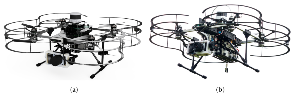
The proposed aerial platform is a custom-built multi-rotor vehicle application tailored for deployment in interiors of structures containing a priceless historical value. The challenges of flying in GNSS-denied environments are tackled by reliance on a high number of onboard sensors with a high emphasis being laid on mission safety by introducing mechanical propeller guards; sensory, power supply and motor redundancy; health and mission monitoring procedures; both low- and high-level obstacle avoidance; and qualitative visual feedback for a human supervisor.
The UAV platform, shown in
Figure 1, is optimized to carry interchangeable sensory equipment required for specific documentation tasks (e.g., cameras, lights, or humidity sensor devices attachable by UAV-wall interaction [
11]) while it minimizes its dimensions to
. The platform flight time is 8
with 8
of the total weight, including stabilized mirrorless camera and onboard sensors for environment perception and obstacle avoidance. The relatively small size is a result of the coaxial configuration of the rotors, which yields an octo-rotor vehicle with significant dimensions reduction. The octo-rotor configuration provides motor redundancy in case of a motor failure. The platform is powered by two 6-cell LiPo 8000
batteries connected in parallel, while the onboard autopilot is being powered by two independent voltage stabilizers to eliminate the most critical single point of failure.
For environment perception, the UAV relies firstly on a 3D laser scanner (Ouster OS0 with 90 deg vertical field of view and 50 range), which is mounted on top of the platform to maximize its view. Secondly, an RGB-D camera (Intel RealSense D435 with 57 deg vertical field of view and 10 range) faces frontward to obtain granular spatial information about the environment in front of the platform. Third, two point-distance lasers are mounted up- and down-ward (Garmin LIDAR-Lite v3 with 40 range) to measure the distance to objects above and below the platform. Last, four ultrasonic sensors (Fermion URM37 with 8 range) are mounted in the horizontal plane of the platform to provide sensory inputs for fast low-level collision avoidance and health monitoring of primary sensors as well as the localization and mapping processes. All these sensors are used in the sensing, acting, and controlling phases. Given the information from these sensors, the UAV localizes itself in the indoor environment, avoids collisions with obstacles, and follows the pre-planned mission using the onboard computational resources.
For documentation purposes, a two-axis camera stabilization gimbal (RoseWhite Dragon capable of stabilizing of payload up to 850 mid-flight) is integrated onto the platform. Such stabilization allows using high-resolution cameras (e.g., mirrorless camera Sony A6500) to obtain quality data during the aerial mission. The payload can be, however, mounted also in an upward-facing direction on a damped platform to capture data on ceilings (this is often required by the experts in the field of restoration). The 3D laser scanner and the RGB-D camera sensors are also used for documentation purposes—to create 3D scans or 3D models online during the mission and to associate the captured documentation data with this spatial information.
3. System Features and Capabilities
The UAV mission can be performed in three different regimes:
Manually, with a trained pilot controlling the UAV remotely while the UAV captures data continuously. The pilot flies with visual feedback on the UAV itself as well as on the real-time video feed from the onboard camera.
Semi-autonomous, with a mission operator commanding the UAV via a computer with real-time visual feedback from the onboard camera and all the onboard sensors. The UAV prevents the operator from colliding with the environment using the onboard sensors in real time. The operator can see in real time all the available sensory data, the captured documentation data, the onboard built maps, and the systems’ health monitoring diagnostics. Data can be captured continuously, it can be triggered by the operator, or it can be captured at pre-specified positions.
Fully-autonomous, with the UAV following a mission plan pre-planned prior to the mission with the mission operator remotely monitoring the summary on health status of all the onboard systems during the flight.
During the fully autonomous mission, the aerial system performs tracking of a pre-planned and pre-verified 3D trajectory, which connects a set of pre-selected positions from which the data should be captured using the onboard documentation sensor (e.g., a camera). Remark that this set of positions can be a single element only if a single detail of an interior element is ought to be captured. In both the semi- and fully-autonomous regimes, a low-level collision prevention system alters the mission plan or the operator command with respect to the onboard sensory data. The need for this is obvious for the semi-autonomous regime—to not allow the operator to potentially collide with the environment—but is also useful in the fully autonomous regime as the apriori map of the environment (i.e., the 3D scan) may contain differences with respect to the reality, such as a ceiling which was not hung up during the ground scanning and is hence missing in the map.
One of the main advantages of gathering images via autonomous flights along paths is the seamless repeatability of the mission. The repeatability feature is advantageous for two major reasons. First, a structure can be documented regularly over long periods of time by seamless mission repetition. This finds its use in temporal monitoring of structural changes or documentation under different day-time lighting. Second, it allows to document the scene with different sensory equipment, which cannot be mounted all at the same time on the aerial platform due to weight and dimensions constraints. In such a case, a mission plan is performed for each documentation sensor, and the data are captured from the exact same positions and angles as handled by the system autonomy.
The entire documentation mission in the semi- and fully autonomous regimes goes as follows:
The historical structure is scanned with a 3D terrestrial laser scanner;
The 3D model of the object is created;
The documentation objects of interest, the desired camera poses, and the desired lighting are specified by the restorers;
The scanning plans (plans connecting all the desired camera positions) are pre-planned within the 3D environment representation by solving the Traveling Salesman Problem;
The plans are checked for any discrepancies or collisions with the environment;
The plans are run in a robotic simulator to verify their feasibility;
The plans are deployed on real-world UAV, and the mission is performed within the pre-scanned structure;
The plans are deployed for a single documentation task or are repeatably deployed in the structure for the purpose of regular inspection or monitoring.
The obtained data are post-processed (e.g., photos are associated with spatial information within the 3D map.
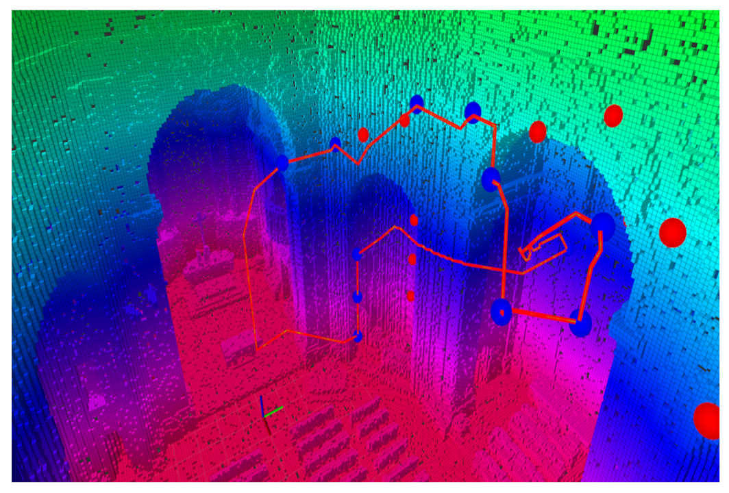
Since the order of visits of particular positions is not given, they can be ordered so that the path connecting all the positions is the shortest one. However, given the set of required camera positions (several hundred up to lower thousands), the UAV with a limited flight time is usually not able to visit all positions during a single flight (see
Figure 2). Combining these two aspects, the generation of the set of scanning plans can be defined as a Traveling Salesman Problem (TSP) considering a limited flight time. Within our system, it is solved using the Lin-Kernighan Heuristic (LKH) known as one of the most efficient heuristics for TSP. The problem of exceeding the maximum flight ime is solved by the division of the overall path in a set of paths connected with a depot point while respecting the constraints on the maximum flight time.
The autonomy of the designed solution relies on and builds on the open-sourced UAV system developed by the Multi-Robot Systems Group at the Czech Technical University in Prague [
22]. The MRS system provides a solution based on Robot Operating System (ROS) suited for precise 3D trajectory tracking, 3D real-time state estimation and localization, inter-robot communication, and a realistic robotic simulation framework. On the baseline of the MRS framework, systems for hardware and software monitoring, path planning, mission planning, verification and visualization, in-map localization, mapping refinement, and visual light-based feedback for the technical crew are tailored for the documentation tasks with a high emphasis on robustness and accuracy in structures lacking access to global navigation systems.
3.1. Remote Control of Photo Capturing
Similarly to various types of flight modes, the proposed system implements multiple modes of photo capturing. The autonomous photo capturing as well as manual triggering of the shutter require the distant control of the camera mounted on the UAV. For this purpose, the UAV is equipped with Seagull #REC2 camera/camcorder controller, which enables to trigger shutter, switch on and off the camera, or evoke the focus based on the commands sent through a serial line by the onboard computer. All these commands can be sent either by the autonomous system running on an onboard computer or remotely by the operator connected to the onboard computer. Apart from controlling of the camera, the Seagull system gives an analog signal when a shutter is triggered, which enables saving of a timestamp for particular images. This is particularly useful for time synchronization between the camera and the onboard running system, as it allows to associate captured data with spatial information.
For the image transmission, this system relies on a small RCD 3016 HD 1920 × 1080 HDMI to AV converter with a Mini HDMI plug that allows us to view the real-time feed from the onboard camera HDMI output to the FPV feed. The entire system for image transmission uses an HDMI to AV converter (on the UAV), an FPV transmitter (on the UAV), and an FPV monitor (with an operator). An example of the system used can be seen in
Figure 3.
The photo capturing itself has two modes of operation with respect to the orientation of the camera—a forward-oriented camera with passive damping and two-axes of control (roll and pitch of the camera) and an upward-facing camera with passive damping only. The pitch-axis control allows for tracking the 3D structure of the scene and provides the capabilities of looking behind valuable objects from above the objects themselves.
3.2. Online Onboard Mapping of the Structure
The proposed system is capable of mapping the entire structure of any historical building by using an onboard mounted 3D LIDAR. We use the Ouster OS0 ultra-wide view high-resolution imaging LiDAR, which offers an ultra-wide 90 vertical field of view with an industry-leading combination of performance, reliability, size, weight, and power. It is designed for indoor/outdoor all-weather environments as well as a long lifetime. As the smallest high-performance LiDAR on the market, the OS0 can be easily integrated into autonomous vehicles, heavy machinery, robots, drones, and mapping solutions. This sensor has a range of 55 , >90% detection probability on 50 , >50% detection probability (with setup Lambertian reflectivity, 1024 @ 10 mode) on 15 , >90% detection probability on 20 , >50% detection probability (with setup Lambertian reflectivity, 1024 @ 10 mode). The minimum range is for point cloud data with an accuracy of ±3 for Lambertian targets or ±10 for retroreflectors, and a resolution of .
The spatial mapping is performed using also the front-facing RGB-D camera. Given position estimates from the simultaneous localization and mapping (SLAM) module for pose estimation of the UAV, the data from both the spatial sensors are transformed to the frame of the apriori scanned map. This frame is obtained from mutual registration of a sparse feature map of the SLAM and a dense apriori map during mission initialization. This registration is performed first globally using the Fast Point Feature Histograms [
23] and then is refined locally using fine-tuning ICP. Without this transformation, the mission start is prevented as the UAVs do not share an identical frame of localization, and the mission plans cannot be transformed to the localization frame.
Given the transformation among the reference frames, the data from the spatial sensors are seamlessly fused to fill in the holes in the apriori map, which are present due to occlusions during terrestrial scanning. The colour information of the RGB-D camera is used to colourify the data produced in the RGB-D camera field of view.
4. Results
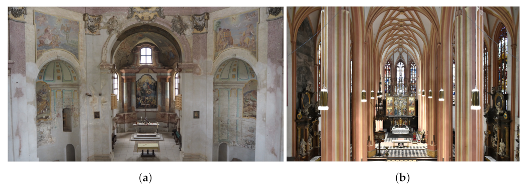
This section presents the results of two sets of experimental runs performed with real UAVs. The first set of the experimental run was performed at St. Anne and St. Jacob the Great Church in Stará Voda containing dark areas in high locations (
Figure 4a). The second set of the experimental run was performed at St. Maurice Church with the set of stained glass located up to 20 m in height (
Figure 4b). The following subsections present the results from both the sites and discuss the performance of the proposed system and the advantage of its usage in comparison to conventional methods.
4.1. Stará Voda
Church of St. Anne and St. Jacob the Great in Stará Voda is an extensive baroque pilgrimage church with two towers. After the Second World War, most of the inventory were relocated and the remaining unmovable decoration was significantly damaged by soldiers during the 40 year period when the church was part of the military area. The program on the renovation of the church began in 1991 and has been in progress till today.
Deployment of the proposed UAV system in this historical monument was targeted at the documentation of photo capturing of paintings and stucco decorations at a height up to 19 m above the ground (see
Figure 5). Since there is no accessible balcony or other structure located higher than the objects of interest, the images cannot be captured from a zero or negative pitch angle without the use of the UAV or some external infrastructure. The photos of paintings captured during these experiments enable to obtain a high-quality image of particular paintings composed from a set of detailed images of partially overlapping areas of the paintings.
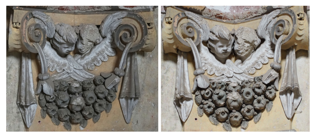
The advantages of the UAVs were further exploited during the documentation of the stuccoes. The three-dimensional objects were documented from several distinct views to avoid occluded parts that cannot be seen in any image. Such documentation is especially important for the restorers since they need to have a complete view of the object to plan the restoration works. The difference between an image from an onboard camera and an image from the handheld camera at the ground is illustrated with one of the images captured in church in Stará Voda shown in
Figure 6. The figure shows an intuitive fact that the image taken by a UAV located at the same height is perpendicular to the scene and hence reveals multiple details that cannot be seen in the image taken from the ground.
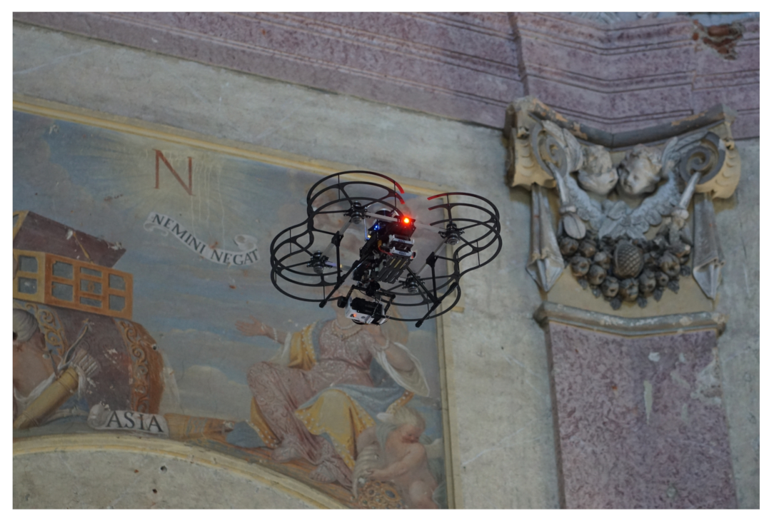
Another documentation technique applied in the church in Stará Voda is the Reflectance Transformation Imaging (RTI) method [
15]. The RTI is a computational photographic method to generate a representation of the image of a captured object that enables its interactive re-lighting from an arbitrary direction and thus reveals details visible only under certain illumination [
24]. The necessary inputs to create such representation are a set of images of an object taken by a camera from a fixed position while the object is illuminated from various known directions. The conventional methods to obtain the desired images [
25,
26] require to have direct access to the object with the ability to position a source of light in the surrounding of the object. This makes these methods unusable for the objects located in areas that are inaccessible to humans. Therefore, for the RTI-based documentation of the stuccoes in Stará Voda, it was necessary to apply the method using UAVs as the carriers of the camera and light [
15]. A photo from the RTI experiment is shown in
Figure 7.
To prove the applicability of the system for 3D mapping of the indoor structures, the proposed system was deployed for mapping of the interior of the church in Stará Voda. Comparison of the obtained map built onboard the UAV during the 300
long documentation mission with the ground truth map obtained from a terrestrial laser scanner is shown in
Figure 8. Although the scan obtained from multiple measurements with the terrestrial laser scanner is more precise and covers some areas that are not accessible with the UAV due to narrow passages (e.g., doors), the scan built by the UAV also contains parts that cannot be scanned from any position feasible for the terrestrial scanner, e.g., upper parts of moldings and bottom parts of window frames or niches. Therefore the UAV is an ideal means for the completion of the missing parts in the scan obtained from the terrestrial scanner or for a rapid scanning with lower requirements on precision.
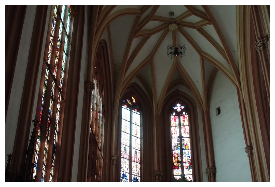
4.2. St. Maurice Church
St. Maurice Church is the main city church in Olomouc that was built in a Gothic style on the base of the former Roman church during the 15th and 16th centuries. In later centuries, the church has been renovated in Renaissance and Baroque style, and it has gained its today appearance during the regothization in the second half of the 19th century.
Together with one of the largest pipe organs in Europe, the main feature of the church and also the main subject of the documentation in St. Maurice Church is the set of 23 stained glass windows located in the nave and presbytery of the temple. They are tall with a pointed arch and stone tracery. Their surface is vertically divided by two or three rods into three or four parts in each window, terminated at the top by a tracery of various shapes (e.g., flamboyant tracery). The stained glass windows reach a height of up to 20 m in the nave, which is itself 22 m high (see
Figure 9). The aim of the documentation was to capture the work before the restoration survey began. It was, therefore, important to take a picture of the unit with high-quality resolution, thanks to which it will be possible to monitor the existing damage in digital form.
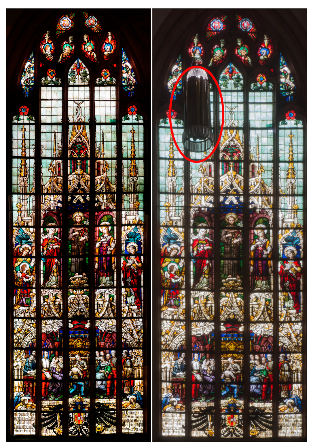
The advantages of the usage of photos captured by UAV in comparison to photos taken from the ground resulted in a lower distance to the object, a higher capability of reaching optimal angle with respect to the captured object (avoiding deformations in the composed image), and the ability to avoid occlusions that are sometimes unavoidable when capturing an object from the ground (e.g., chandelier in
Figure 10). Satisfactory results can be seen at
Figure 10. Additional results of the project are presented at project’s websites
www.dronument.cz and
mrs.felk.cvut.cz/dronument (accessed on 27 August 2021) (
Supplementary Materials).
5. Lessons Learned
The documentation of the historical buildings with the use of UAVs requires strong interdisciplinary cooperation between experts from the field of history, restoration, and robotics. Since the fields of robotics and history and restoration are not usually interconnected, the terminology used in these fields significantly differs. As mentioned in
Figure 3, one of the first steps of the documentation of particular objects is the definition of the documentation task. This means defining all objects, positions, and techniques with which they should be scanned. Although the choice of particular objects and optimal methods for their documentation is the work of restorers and historians, the roboticists are involved in this discussion to conclude on the feasibility of realizing the desired methods at defined positions with respect to safety from the robotic point of view. Therefore, the cooperation is naturally getting more effective with increasing knowledge of the involved experts in other disciplines.
Based on our experience gained during scanning procedures realized in particular objects, it is important to note that the proposed UAV system is not the optimal mean for the realization of all documentation techniques in every historical building. Although the UAV platform allows to realize some techniques and capture images out of the common reach of humans, there are still many situations when capturing an image by a handheld camera or a camera mounted on the tripod provides better results in a less costly way. This fact is often omitted by the potential end-users of the proposed UAV technology, which results in requirements that are not reasonable neither from the quality, nor from the cost, nor the safety point of view. To provide an example, it is advantageous to use the UAV when the large scaffolding has to be built, but not in the case when a stepladder would suffice.
The key aspect of almost every work performed in a priceless environment is safety. Although the autonomy of the UAV can help avoid human failures, it is essential to implement and perform a significant amount of health monitoring procedures that improve the reliability of the entire system. The first group of security checks, which has to be performed by a human operator, includes the control of essential mechanical and electronic parts and their proper assembly. The second stage of security checks is implemented based on data from sensors and algorithms running on the onboard computer of the UAV. Thus these checks can be evaluated by the UAV itself, and the UAV is eligible to refuse the mission if any safety condition is unmet. After the UAV itself approves the mission, the final checks lay again on the human operator. At this stage, the mission-specific data that were produced by the algorithms running onboard the UAV are evaluated to maximize the safety of the documentation mission.
During the numerous experimental deployments of the system, the visualization proves to be the most helpful tool for the final stage of security checks as well as for checking the correctness of the mission from the documentation point of view. From the human perspective, the joint visualization of different kinds of maps, plans, and sensory data gathered by the UAV seems to be the most proper way to understand the current state and aims of the UAV and to detect possible failures.
6. Conclusions
In this manuscript, we proposed a novel unmanned aerial vehicle to perform the documentation of historical buildings and cultural heritage monuments. The platform is equipped with several sensors for environment perception (i.e., RGB cameras, depth cameras, LiDAR scanners, etc.). Apart from necessary sensors for an autonomous flight, the UAV carries also the sensor for gathering data only for documentation of the scanned structure. The proposed UAV enables flight on a different level of autonomy, precise navigation to desired places, and distant triggering of the shutter of an onboard camera. The platform was tested in two chosen historical places: the Church of St. Anne and St. Jacob the Great in Stará Voda and the St. Maurice Church in Olomouc, Czech Republic. These places contain several interesting features such as places with poor lightening, stained glass windows, and sculptural decoration with varying degrees of damage that cannot be captured under the desired angle from the ground. The advantage of UAV photo capturing was demonstrated with results comparing the photomap of stained glass windows obtained from images captured by the proposed UAV system and images captured from the ground. The proposed UAV system for documentation of historical buildings can not only provide valuable data for restorers and historians but also avoid the risks involved in reaching high places inside these buildings.
Author Contributions
Conceptualization, Vít Krátký and Pavel Petráček; methodology, Pavel Petráček, Vít Krátký, Michaela Čadilová and Milan Škobrtal; software, Vít Krátký and Pavel Petráček; validation, Pavel Petráček, Vít Krátký, Milan Škobrtal and Pavel Stoudek; formal analysis, Pavel Petráček and Vít Krátký; investigation, Vít Krátký, Pavel Petráček and Milan Škobrtal; resources, Milan Škobrtal; data curation, Vít Krátký, Pavel Petráček, Michaela Čadilová and Milan Škobrtal; writing—original draft preparation, Tiago Nascimento, Vít Krátký and Pavel Petráček; writing—review and editing, Pavel Petráček, Vít Krátký and Tiago Nascimento; visualization, Vít Krátký, Pavel Petráček and Pavel Stoudek; supervision, Martin Saska and Michaela Čadilová; project administration, Milan Škobrtal, Martin Saska, Vít Krátký and Pavel Petráček; funding acquisition, Martin Saska and Michaela Čadilová. All authors have read and agreed to the published version of the manuscript.
Funding
This work was supported in part by project DG18P02OVV069 in program NAKI II, in part by CTU under Grant SGS20/174/OHK3/3T/13, by European Union’s Horizon 2020 research and innovation programme AERIAL-CORE under grant agreement no. 871479, and in part by Ministry of Education of the Czech Republic through OPVVV project under Grant CZ.02.1.01/0.0/0.0/16 019/00007.
Data Availability Statement
Acknowledgments
The authors would like to thank Tomáš Báča and Matěj Petrlík for their help with performing real world experiments.
Conflicts of Interest
The authors declare no conflict of interest. The funders had no role in the design of the study; in the collection, analyses, or interpretation of data; in the writing of the manuscript, or in the decision to publish the results.
References
- Bentkowska-Kafel, A.; MacDonald, L. (Eds.) Digital Techniques for Documenting and Preserving Cultural Heritage; Amsterdam University Press: Amsterdam, The Netherlands, 2018. [Google Scholar]
- Baik, A. The Use of Interactive Virtual BIM to Boost Virtual Tourism in Heritage Sites, Historic Jeddah. ISPRS Int. J. -Geo 2021, 10, 577. [Google Scholar] [CrossRef]
- Balletti, C.; Ballarin, M. An Application of Integrated 3D Technologies for Replicas in Cultural Heritage. ISPRS Int. J. -Geo 2019, 8, 285. [Google Scholar] [CrossRef] [Green Version]
- McCarthy, J. Multi-image photogrammetry as a practical tool for cultural heritage survey and community engagement. J. Archaeol. Sci. 2014, 43, 175–185. [Google Scholar] [CrossRef]
- Gomes, L.; Bellon, O.R.P.; Silva, L. 3D reconstruction methods for digital preservation of cultural heritage: A survey. Pattern Recognit. Lett. 2014, 50, 3–14. [Google Scholar] [CrossRef]
- Jo, Y.H.; Hong, S. Three-Dimensional Digital Documentation of Cultural Heritage Site Based on the Convergence of Terrestrial Laser Scanning and Unmanned Aerial Vehicle Photogrammetry. ISPRS Int. J. Geo-Inf. 2019, 8, 53. [Google Scholar] [CrossRef] [Green Version]
- Murtiyoso, A.; Grussenmeyer, P. Documentation of heritage buildings using close-range UAV images: Dense matching issues, comparison and case studies. Photogramm. Rec. 2017, 32, 206–229. [Google Scholar] [CrossRef] [Green Version]
- Bacco, M.; Barsocchi, P.; Cassará, P.; Germanese, D.; Gotta, A.; Leone, G.R.; Moroni, D.; Pascali, M.A.; Tampucci, M. Monitoring Ancient Buildings: Real Deployment of an IoT System Enhanced by UAVs and Virtual Reality. IEEE Access 2020, 8, 50131–50148. [Google Scholar] [CrossRef]
- Cafolla, D.; Russo, M.; Cecarelli, M. Experimental Validation of HeritageBot III, a Robotic Platform for Cultural Heritage. J. Intell. Robot. Syst. 2020, 100, 223–237. [Google Scholar] [CrossRef]
- Solla, M.; Gonçalves, L.M.S.; Gonçalves, G.; Francisco, C.; Puente, I.; Providência, P.; Gaspar, F.; Rodrigues, H. A Building Information Modeling Approach to Integrate Geomatic Data for the Documentation and Preservation of Cultural Heritage. Remote Sens. 2020, 12, 4028. [Google Scholar] [CrossRef]
- Smrcka, D.; Baca, T.; Nascimento, T.; Saska, M. Admittance Force-Based UAV-Wall Stabilization and Press Exertion for Documentation and Inspection of Historical Buildings. In Proceedings of the 2021 International Conference on Unmanned Aircraft Systems (ICUAS), Athens, Greece, 15–18 June 2021; pp. 552–559. [Google Scholar]
- Deng, F.; Zhu, X.; Li, X.; Li, M. 3D Digitisation of Large-Scale Unstructured Great Wall Heritage Sites by a Small Unmanned Helicopter. Remote Sens. 2017, 9, 423. [Google Scholar] [CrossRef] [Green Version]
- Petráček, P.; Krátký, V.; Saska, M. Dronument: System for Reliable Deployment of Micro Aerial Vehicles in Dark Areas of Large Historical Monuments. IEEE Robot. Autom. Lett. 2020, 5, 2078–2085. [Google Scholar] [CrossRef]
- Saska, M.; Krátký, V.; Spurný, V.; Báča, T. Documentation of dark areas of large historical buildings by a formation of unmanned aerial vehicles using model predictive control. In Proceedings of the 2017 22nd IEEE International Conference on Emerging Technologies and Factory Automation (ETFA), Limassol, Cyprus, 12–15 September 2017; pp. 1–8. [Google Scholar]
- Krátký, V.; Petráček, P.; Spurný, V.; Saska, M. Autonomous Reflectance Transformation Imaging by a Team of Unmanned Aerial Vehicles. IEEE Robot. Autom. Lett. 2020, 5, 2302–2309. [Google Scholar] [CrossRef]
- Murtiyoso, A.; Grussenmeyer, P.; Suwardhi, D.; Sumantri, D.; Wahyu, S.; Purnama, l.; Murtiyoso, S.; Ndryana, G.A.; Awalludin, R. Digital Documentation Workflow and Challenges for Tropical Vernacular Architecture in the Case of the Kasepuhan Palace in Cirebon, Indonesia. In Proceedings of the 2018 3rd Digital Heritage International Congress (DigitalHERITAGE) Held Jointly with 2018 24th International Conference on Virtual Systems Multimedia (VSMM 2018), San Francisco, CA, USA, 26–30 October 2018; pp. 1–4. [Google Scholar]
- Zlot, R.; Bosse, M.; Greenop, K.; Jarzab, Z.; Juckes, E.; Roberts, J. Efficiently capturing large, complex cultural heritage sites with a handheld mobile 3D laser mapping system. J. Cult. Herit. 2014, 15, 670–678. [Google Scholar] [CrossRef]
- Hess, M.; Petrovic, V.; Meyer, D.; Rissolo, D.; Kuester, F. Fusion of multimodal three-dimensional data for comprehensive digital documentation of cultural heritage sites. In 2015 Digital Heritage; IEEE: Piscataway, NJ, USA, 2015; Volume 2, pp. 595–602. [Google Scholar]
- Brutto, M.L.; Borruso, A.; D’Argenio, A. Uav Systems for Photogrammetric Data Acquisition of Archaeological Sites. Int. J. Herit. Digit. Era 2012, 1, 7–13. [Google Scholar] [CrossRef] [Green Version]
- Bakirman, T.; Bayram, B.; Akpinar, B.; Karabulut, M.F.; Bayrak, O.C.; Yigitoglu, A.; Seker, D.Z. Implementation of ultra-light UAV systems for cultural heritage documentation. J. Cult. Herit. 2020, 44, 174–184. [Google Scholar] [CrossRef]
- Hallermann, N.; Morgenthal, G.; Rodehorst, V. Vision-based monitoring of heritage monuments – Unmanned Aerial Systems (UAS) for detailed inspection and high-accurate survey of structures. WIT Trans. Built Environ. 2015, 153, 621–632. [Google Scholar]
- Baca, T.; Petrlik, M.; Vrba, M.; Spurny, V.; Penicka, R.; Hert, D.; Saska, M. The MRS UAV System: Pushing the Frontiers of Reproducible Research, Real-world Deployment, and Education with Autonomous Unmanned Aerial Vehicles. J. Intell. Robot. Syst. 2021, 102, 1–28. [Google Scholar] [CrossRef]
- Rusu, R.B.; Blodow, N.; Beetz, M. Fast Point Feature Histograms (FPFH) for 3D registration. In Proceedings of the 2009 IEEE International Conference on Robotics and Automation, Kobe, Japan, 12–17 May 2009; pp. 3212–3217. [Google Scholar]
- Malzbender, T.; Gelb, D.; Wolters, H. Polynomial Texture Maps. In 28th Annual Conference on Computer Graphics and Interactive Techniques; ACM: New York, NY, USA, 2001. [Google Scholar]
- Cosentino, A. Macro Photography for Reflectance Transformation Imaging: A Practical Guide to the Highlights Method. E-Conserv. J. 2013, 1, 70–85. [Google Scholar] [CrossRef]
- Cultural Heritage Imaging. Reflectance Transformation Imaging. 2019. Available online: http://culturalheritageimaging.org/Technologies/RTI (accessed on 5 August 2021).
| Publisher’s Note: MDPI stays neutral with regard to jurisdictional claims in published maps and institutional affiliations. |
© 2021 by the authors. Licensee MDPI, Basel, Switzerland. This article is an open access article distributed under the terms and conditions of the Creative Commons Attribution (CC BY) license (https://creativecommons.org/licenses/by/4.0/).


 ,
, 