Article

Pairwise Coarse Registration of Indoor Point Clouds Using 2D Line Features

1
College of Hydraulic Science and Engineering, Yangzhou University, Jiangyang Middle Road 131, Yangzhou 225009, China
2
School of Geodesy and Geomatics, Wuhan University, Wuhan 430079, China
3
College of Earth Sciences, Chengdu University of Technology, Erxianqiao Dongsan Road 1, Chengdu 610059, China
4
Faculty of Geomatics, East China University of Technology, Nanchang 330013, China
5
Key Laboratory for Digital Land and Resources of Jiangxi Province, East China University of Technology, Nanchang 330013, China
*
Author to whom correspondence should be addressed.
ISPRS Int. J. Geo-Inf. 2021, 10(1), 26; https://doi.org/10.3390/ijgi10010026
Submission received: 26 October 2020 / Revised: 24 December 2020 / Accepted: 11 January 2021 / Published: 12 January 2021
(This article belongs to the Special Issue 3D Indoor Mapping and Modelling)

Abstract

:
Registration is essential for terrestrial LiDAR (light detection and ranging) scanning point clouds. The registration of indoor point clouds is especially challenging due to the occlusion and self-similarity of indoor structures. This paper proposes a 4 degrees of freedom (4DOF) coarse registration method that fully takes advantage of the knowledge that the equipment is levelled or the inclination compensated for by a tilt sensor in data acquisition. The method decomposes the 4DOF registration problem into two parts: (1) horizontal alignment using ortho-projected images and (2) vertical alignment. The ortho-projected images are generated using points between the floor and ceiling, and the horizontal alignment is achieved by the matching of the source and target ortho-projected images using the 2D line features detected from them. The vertical alignment is achieved by making the height of the floor and ceiling in the source and target points equivalent. Two datasets, one with five stations and the other with 20 stations, were used to evaluate the performance of the proposed method. The experimental results showed that the proposed method achieved 80% and 63% successful registration rates (SRRs) in a simple scene and a challenging scene, respectively. The SRR in the simple scene is only lower than that of the keypoint-based four-point congruent set (K4PCS) method. The SRR in the challenging scene is better than all five comparison methods. Even though the proposed method still has some limitations, the proposed method provides an alternative to solve the indoor point cloud registration problem.

1. Introduction

The easy access to high-quality dense point clouds means that LiDAR (light detection and ranging) scanning has been widely used in areas such as surveying and mapping [1], forestry inventory [2], and hazard monitoring [3] during the last two decades. In recent years, indoor point clouds have become more and more desirable for applications in interactive visualization [4], as-built construction [5,6], indoor navigation [7], and building model reconstruction [8,9]. Cost-effective, convenient, and efficient methods for producing high-quality indoor point clouds are expected.
Various methods and equipment can be employed to acquire indoor point clouds. Traditional terrestrial laser scanning (TLS) is probably the most basic method used to obtain indoor point clouds. TLS can acquire high-accuracy point clouds, but it needs to scan station by station to cover the full view of the indoor scene. Mobile indoor mapping systems, such as NavVis [10], can acquire dense indoor point clouds in a moving mode, which is convenient and efficient, but the accuracy of the produced point clouds is lower than that of TLS. RGB-depth (RGB-D) sensors such as Intel RealSense [11] and Microsoft Kinect [12] are more and more used in indoor data acquisition for their low cost and portability.
Registration is essential for TLS-based and RGB-D-based indoor point cloud acquisition methods. Registration transforms point clouds scanned from different stations to a unified coordinate system to cover the entire scene completely. The registration can be categorized into pairwise registration and multi-view registration depending on the station number of input point clouds. Pairwise registration is the basis and foundation of multi-view registration. Besides this, a coarse-to-fine strategy is usually used to improve the efficiency of pairwise registration. The coarse step finds the initial registration parameters quickly and serves as the input of fine registration. The fine registration step obtains the optimal registration parameters. The iterative closest point (ICP) algorithm [13] and its variants [14,15] and the normal distribution transform (NDT) algorithm [16] and its variants [17,18] are among the most famous and widely used fine registration algorithms.
This paper focuses on the pairwise coarse registration of point clouds, which plays an important role in point cloud processing. A variety of methods have been developed to accomplish robust, efficient, and high-accuracy coarse registration. These methods can mainly be divided into two categories: (1) feature-based registration methods and (2) probabilistic registration methods.
Among feature-based registration methods, hand-crafted features are the most widely and commonly used features. In this kind of registration method, geometric features (such as points, curves, planes, and surfaces) are first extracted from point clouds, and then correspondences are identified from these geometric features. Finally, the rigid transformation between point clouds is estimated based on the identified corresponding geometric features. Spin images [19] and Extended Gaussian Images (EGI) [20] are among the classical point features that used to register point clouds. To better describe local geometry, Rusu et al. [21] proposed 16-dimensional (16D) features named persistent feature histograms (PFHs) and applied them to registering point clouds. The computation of PFH features is time-consuming. Rusu et al. [22] improved the PFH feature and proposed fast point feature histograms (FPFHs). To be more time-efficient, Dong et al. [23] proposed a binary descriptor named the binary shape context (BSC) for object recognition and point cloud registration. The BSC descriptor was proved to have a high descriptiveness, strong robustness, and high efficiency in both time and memory.
Point features such as Spin images, EGI, PFH, FPFH, and BSC are theoretically suitable for any kind of point clouds. However, the performance is declined in some cases. In such cases, high-level geometric features, such as lines, planes, and semantic features, are used to improve point clouds’ registration performance. Yang and Zang [24] extracted crest lines from TLS point clouds and a deformation model was used as a similarity measure to match the extracted crest lines. Planar patches were extracted and matched for 3D laser scanning data registration in [25]. Tree stems were extracted and matched to register point clouds acquired in forestry in [26]. High-level geometric features such as crest lines, planar patches, and tree stems are usually only suitable for point clouds scanned in specific scenes.
Effective and robust hand-crafted features are difficult to design. In recent years, the deep learning method has been used to learn high-level descriptive features from large amounts of training data directly and automatically. Zeng et al. [27] proposed a volumetric patch-based network to learn correspondences for RGB-D data registration. Similarly, Zhang et al. [28] proposed to learn 3D deep features from volumetric patches for the registration of mobile laser scanning point clouds obtained in different phases. In contrast to learning features from volumetric patches, Alba et al. [29] projected the neighborhood of key points to 2D RGB-D patches and learned features using the standard 2D convolutional neural network. Based on PointNet [30], Deng et al. [31] proposed the point pair feature network (PPFNet) to learn globally informed 3D local feature descriptors directly from unordered points. Similarly, Aoki et al. [32] thought of PointNet as a learnable “imaging” function and thus used the Lucas–Kanade algorithm to achieve the alignment of point clouds.
Besides hand-crafted features and deep learning learnt features, the four-point congruent set (4PCS) is another special feature proposed to register point clouds. 4PCS-based registration methods first extract coplanar four-point-wide bases from source and target points. Affine invariant ratios are defined using base points to find candidate correspondences between wide bases in source and target points. Candidate transformations are estimated based on the candidate 4PCS correspondence, and the one that transforms the source points to have the most points close to the targets points is selected as the optimal and final transformation. The 4PCS algorithm works well for datasets with small overlaps and is resilient to noise and outliers, but is time-consuming for large-scale datasets. To improve its time efficiency, some variants have been developed based on the original 4PCS algorithm. Mellado et al. [33] improved the original 4PCS algorithm by introducing a smart indexing data organization to reduce the quadratic time complexity to linear time complexity. The improved algorithm is called SUPER 4PCS. Keypoint-based 4PCS (K4PCS), proposed by Theiler et al. [34], improves the time efficiency by first extracting keypoints from point clouds and then feeding the keypoints to the 4PCS algorithm, instead of using all points in the source and target points. Similar to K4PCS, Ge [35] proposed to extract semantic keypoints first and then feed the extracted semantic keypoints to the 4PCS algorithm.
Feature-based registration methods accomplish point cloud registration by matching feature correspondences in source and target point clouds. Meanwhile, the probabilistic registration method model uses the distribution of point clouds as a density function and performs registration either by employing a correlation-based approach or using an expectation maximization-based optimization framework [36]. Tsin and Kanade [37] proposed to use a kernel correlation function to measure the affinity between point clouds and register point clouds by finding the maximum kernel correlation using an M-estimator. Jian and Vemuri [38] proposed a unified framework for rigid and nonrigid point cloud registration which uses Gaussian mixture models to represent the point clouds and register the input point clouds by minimizing the statistical discrepancy measure between the two Gaussian mixtures. Myronenko and Song [39] proposed the coherent point drift (CPD) algorithm, which fits the Gaussian mixture model centroids of the source point cloud to the target point cloud by maximizing the likelihood in a way that forces the GMM centroids to move coherently as a group to preserve the topological structure of the point sets.
Even though coarse point cloud registration has been widely studied for a long time, it is still challenging due to the scene complexity, sparse distribution, occlusion, and noises of point clouds, especially for indoor point clouds. Compared with outdoor scenes, indoor scenes have their own characteristics: (1) many self-similarity structures exist and (2) they have much more structured geometric features. The registration of indoor scene point clouds can achieve a better performance if its own characteristics are fully considered. Bueno et al. [6] proposed to extract keypoints from indoor point clouds and then feed the keypoints to a 4PCS algorithm to achieve the registration of indoor point clouds. This method is similar to the K4PCS algorithm [34] for outdoor scenes, and the characteristics of the indoor point clouds are not considered. Tsai and Huang [40] designed an indoor 3D reconstruction system using pan-tilt and an RGB-D sensor. An algorithm to automatically register the data acquired in a fixed station was developed but the global registration of different stations was not presented. Mahmood et al. [5] extracted lines from a horizontal cross-section and registered the as-built model to an as-planned model using the line feature correspondences. This method is suitable for the registration of a point cloud of part of a building (such as a room) to the full building information model (BIM) but not for station-by-station point cloud registration. Sanchez et al. [41] proposed the structured scene feature-based registration (SSFR) algorithm that uses Gaussian images to find corresponding planes for the registration of indoor point clouds that have planes. The SSFR algorithm is not suitable for complex indoor scenes since its plane number is set as constant. Pavan et al. [42] proposed a plane-to-plane correspondences-based method for indoor and outdoor building point cloud registration. Planes are segmented first using the random sample consensus (RANSAC) algorithm and then the planes are matched using complex numbers. Finally, the transformation is estimated using the plane correspondences. This method is time-consuming due to the RANSAC segmentation step.
The rigid transformation between point clouds has six degrees of freedom (DOF) if it does not have any constraints and can be expressed by three translations and three rotation angles. For the state-of-the-art scanners, the inclination of equipment in data acquisition can be compensated by the built-in tilt sensor, and thus the rotation between point clouds scanned from different stations is constrained to azimuth only. Based on this assumption, Cai et al. [43] proposed a fast branch-and-bound (BnB) algorithm based on 3D keypoint correspondences for a 1D rotation search and thus achieved a computationally efficient 4 degrees of freedom (4DOF) registration. In our previous work [44], a two-step 4DOF registration algorithm for outdoor scenes is proposed. In the first step, the horizontal translation and azimuth angle is estimated by the keypoint-based registration of ortho-projected feature images. In the second step, the vertical translation is estimated by the height difference of the overlapping areas after they are horizontally aligned. Ge and Hu [45] proposed a three step 4DOF registration algorithm for urban scene point clouds. In the first step, the 2D transformation was estimated using the matched line primitives. In the second step, the vertical offset was compensated by least squares optimization. Finally, the full transformation was refined by a least squares algorithm using the uniformly sampled patches.
This paper proposes a 4DOF coarse registration algorithm for indoor point clouds. Similar to our previous work [44], the 4DOF registration is divided into two steps. The first step achieves 2D registration in the horizontal plane. The second step aligns the point clouds in the vertical plane after they are horizontally aligned. Differing from our previous work, this paper proposes a new method to generate ortho-projected images for indoor point clouds and achieves horizontal alignment by matching the 2D line features in the ortho-projected images rather than using the keypoint-based registration method. Besides this, this paper achieves vertical alignment by making the heights of the floor and ceiling in the source point cloud and the target point cloud equivalent rather than making the heights of the overlapping regions equivalent.
The remainder of this paper is structured as follows. In Section 2, the used indoor point cloud datasets are introduced, and the proposed registration method is described in detail. In Section 3, the results are presented. In Section 4, we briefly discuss the proposed method and the results. Finally, the conclusions are given in Section 5.

2. Materials and Methods

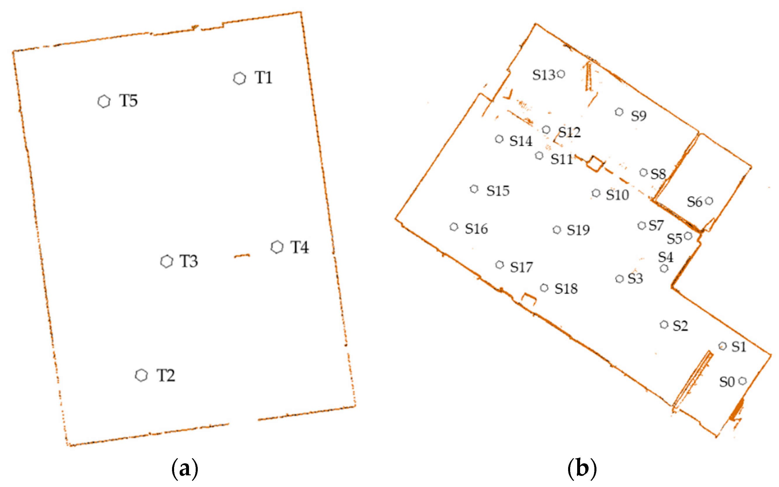
2.1. Indoor Point Cloud Datasets

Two datasets were used to validate the proposed method. The first one, provided by ETH Zurich (https://ethz.ch/content/dam/ethz/special-interest/baug/igp/photogrammetry-remote-sensing-dam/documents/sourcecode-and-datasets/PascalTheiler/office.zip) and abbreviated as SR, contains five scans of an indoor office (Figure 1a). All five scans overlap each other, and thus a total of 10 pairs of matching can be conducted (Table 1). The ground truth transformations between pairs are provided by ETH Zurich. The second one, provided by Wuhan RGSpace Technology Co. LTD (http://rgspace.com/) and abbreviated as CB, contains 20 scans of the interior of a building (Figure 1b). The point clouds were captured by a self-integrated scanner using three Azure Kinect DKs (https://azure.microsoft.com/en-us/services/kinect-dk/). The Azure Kinect DKs were operated in a WFOV (wide field-of-view) 2 × 2 binned mode in data acquisition and thus the scanning range was less than 2.9 m. The scanner was leveled using tilt sensors with a 0.1 degree precision and rotated around z axis with a pre-calibrated fixed angle interval (30 degrees) in data acquisition. The relative relationships between the Azure Kinect DK sensors were also carefully calibrated, and thus all the data scanned in a station can be transformed to a unified coordinate system. A total of 19 pairs of matching was conducted to ensure that all the 20 scans could be registered to the points of the first scan station. The ground truth transformations between pairs were provided by Wuhan RGSpace Technology Co. LTD. The pairs used to conduct experiments and other details can be found in Table 1.

2.2. Registration Method

The proposed indoor point cloud registration method assumes that the equipment is leveled or that the inclination is compensated by tilt sensors in data acquisition. The whole process of registration is achieved by three steps: (1) ortho-projected image generation, (2) ortho-projected image registration using 2D line features, and (3) point cloud registration. The overview of the proposed registration method is illustrated in Figure 2.

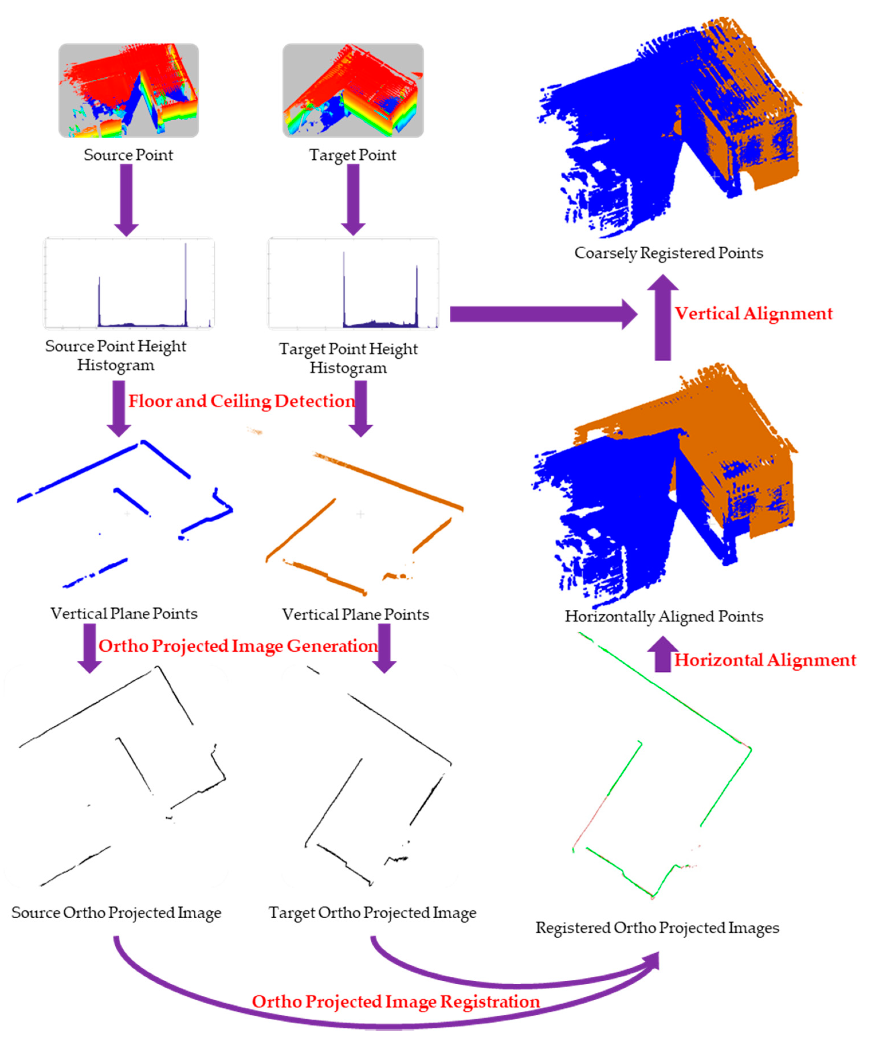
2.2.1. Registration Framework

The rigid transformation between source point clouds and target point clouds without any constraints can be written as:
[ x t y t z t ] = [ t x t y t z ] + R ( α ) R ( β ) R ( θ ) [ x s y s z s ] ,
where [ x s y s z s ] T is the source point and [ x t y t z t ] T is the target point. [ t x t y t z ] T is the translation vector between the source points and target points. α ,   β , θ are the rotation angles between the source points and target points. If the equipment is levelled or the inclination is compensated by a tilt sensor in data acquisition, then α and β are equal to zero. In such a situation, Equation (1) can be written as:
[ x t y t z t ] = [ t x t y t z ] + R ( θ ) [ x s y s z s ] ,
or
[ x t y t z t ] = [ t x t y t z ] + [ cos θ sin θ 0 sin θ cos θ 0 0 0 1 ] [ x s y s z s ] .
Equation (3) can be reformatted as:
[ x t y t z t ] = [ 0 0 t z + z s 1 ] + [ cos θ sin θ t x sin θ cos θ t y 0 0 1 ] [ x s y s 1 ] ,
or
[ x t y t z t ] = [ 0 0 t z + z s 1 ] + [ R t x y 0 1 ] [ x s y s 1 ] .
From Equation (5), we can conclude that the 4DOF registration can be decomposed into two steps: (1) the first step estimates the horizontal translation vector and rotation angle around the z axis (named as azimuth angle in the following), which corresponds to [ R , t x y ] ; (2) the second step estimates vertical translation, t z .
The estimation of the horizontal translation vector and the azimuth angle is equivalent to the registration of the ortho images of source points and target points. This paper uses vertical plane points such as walls and doors to generate point cloud ortho-projected images to achieve the estimation of the horizontal translation vector and azimuth angle. After being horizontally aligned, the vertical translation is estimated using the height difference of the floor and ceiling in the source and target points.

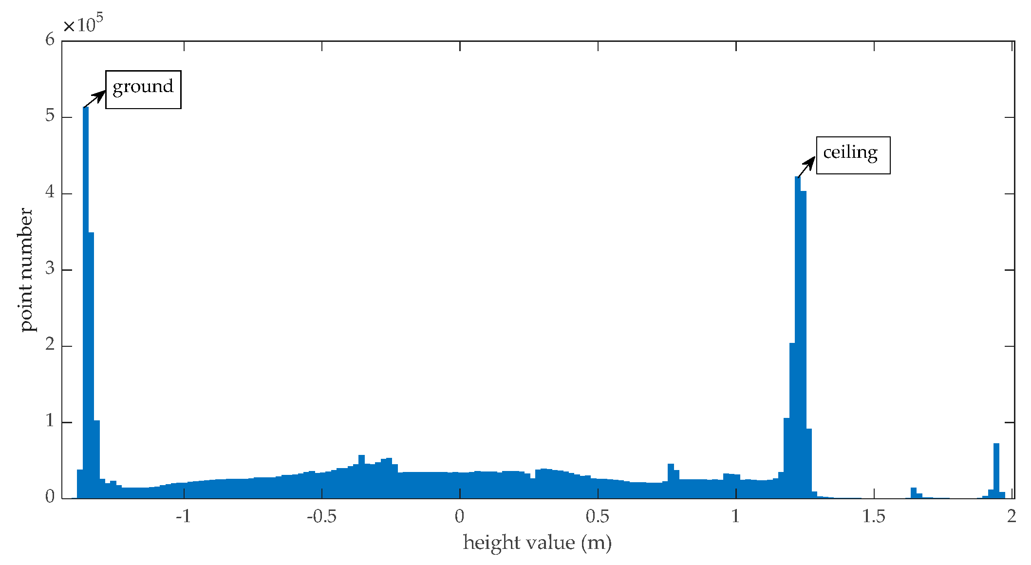
2.2.2. Ortho-Projected Image Generation

Vertical plane points such as walls and doors are used to generate ortho-projected images. To get vertical plane points, the ground points and ceiling points are first eliminated from the raw indoor point clouds. It is obvious that the ground and ceiling have the most points in the height histogram, as illustrated in Figure 3, so we can find the height of the ground and ceiling using the height histogram and eliminate the points with z values smaller than the ground height and points with z values higher than the ceiling height.
Since the equipment is mounted above the floor and the coordinate origin of the sensor is on the equipment, the z values of the floor points are certainly smaller than zero and the z values of ceiling points are certainly larger than zero. The height of the floor points can be found by fitting under the zero part of a height histogram using extreme value distribution. Accordingly, the height of ceiling points can be found by fitting above the zero part of the height histogram using extreme value distribution. The probability density function used in this paper is defined as Equation (6). In Equation (6), μ is the location of the maximum value and s is a scale parameter.
y = 1 s e ( x μ ) / s e e ( x μ ) / s .
After the heights of the floor (denoted as h f ) and ceiling (denoted as h c ) are found, to eliminate moving objects only points with z values between h f + d h f and h c d h c are used to generate ortho-projected images. In this paper, d h f = 3 5 ( h c h f ) and d h c = 1 5 ( h c h f ) are used to avoid moving objects on the floor and hanging objects on the ceiling.
Before registration, the source and target points are all in the scanner-owned coordinate system. To generate ortho-projected images of a station point cloud (source points or target points), the minimum x and y values (denoted as x m i n   and   y m i n ) of that station point cloud are found. For a point ( x , y , z ) , its row number and column number in the ortho-projected image are obtained by Equations (7) and (8). L is the grid resolution of the ortho-projected images. Theoretically, the smaller the L , the better the matching accuracy but the higher the computing complexity. To compromise between accuracy and computing complexity, L is empirically set to 0.01 m in this paper. If a pixel in an ortho-projected image contains at least one point, its pixel value is set to 255. Otherwise, the pixel value is set to 0. In such a way, we can obtain a binary ortho-projected image for the source points and target points.
row = INT ( y y m i n L ) ,
col = INT ( x x m i n L ) .

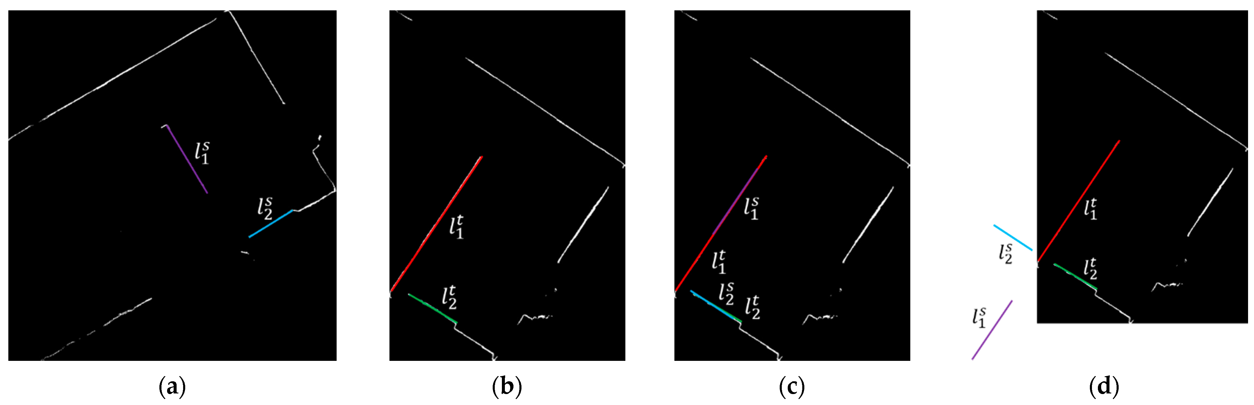
2.2.3. Ortho-Projected Images Registration

The ortho-projected images are binary images, and line features are the most frequently occurring features in the ortho-projected images. This paper uses a line-based algorithm to register the ortho-projected images. The lines in the ortho-projected images are not single-pixel lines; to better detect lines, the ortho-projected images are first thinned by the Zhang–Suen thinning algorithm [46]. Then, the progressive probabilistic Hough transform algorithm [47] is used to detect lines. Finally, the ortho-projected images are registered using the detected 2D lines. The following part of this section are details to register the source and target ortho-projected images using the detected lines.
The points ( x , y ) and ( X , Y ) in the source ortho-projected images and target ortho-projected images in the Cartesian coordinates can be written in the homogeneous coordinates [ x   y   1 ] T and [ X   Y   1 ] T , respectively, where T denotes transpose. The relation between the source ortho-projected image point [ x   y   1 ] T   and target ortho-projected image point [ X   Y   1 ] T can be written as:
[ X Y 1 ] = [ cos θ sin θ t x sin θ cos θ t y 0 0 1 ] [ x y 1 ] ,
or
P = R p .
If a x + b y + 1 = 0 is a line in the source ortho-projected image in Cartesian coordinates, the same line in homogenous coordinates can be written as:
[ a b 1 ] [ x y 1 ] = 0 ,
or
l T p = 0 ,
where l T = [ a b 1 ] is the parameter of a line in a source ortho-projected image. Similarly, line A x + B y + 1 = 0 in a target ortho-projected image in Cartesian coordinates can be written as:
[ A B 1 ] [ X Y 1 ] = 0 ,
or
L T P = 0 ,
where L T = [ A B 1 ] is the parameter of a line in a target ortho-projected image. Left multiplying both sides of Equation (10) by L T , we obtain:
L T P = L T R p .
From Equation (14), we know that the left side of Equation (15) is 0. Thus, the right side of Equation (15) is 0, which means:
L T R p = 0 .
Combining Equations (12) and (16), it can be concluded that:
L T R = λ l T ,
where λ is a scale parameter.
Equation (17) establishes the relation between line parameters in source and target ortho-projected images and the transformation between these two ortho-projected images. Equation (17) can be written in the detailed form as:
A cos θ + B sin θ = λ a ,
A sin θ + B cos θ = λ b ,
A t x + B t y + 1 = λ .
Substituting Equation (20) into Equations (18) and (19), we obtain two equations (Equations (21) and (22)) relating unknown registration parameters ( θ , t x , t y ) to the parameters of corresponding lines in the source and target ortho-projected images.
A cos θ + B sin θ a A t x a B t y a = 0 ,
A sin θ + B cos θ b A t x b B t y b = 0 .
In Equations (21) and (22), a and b are the parameters of a line in a source ortho-projected image, while A and B are the parameters of the corresponding line in a target ortho-projected image. a , b , A , and B are obtained from the result of a progressive probabilistic Hough transform algorithm. Thus, there are only three unknown parameters ( θ , t x , t y ) , which we need to solve, in Equations (21) and (22). If we obtain two non-parallel corresponding lines in source and target ortho-projected images, we have four equations to solve the three unknown registration parameters, and thus the unknown registration parameters can be estimated by a least squares algorithm after a linearization or non-linear optimization algorithm, such as the Levenberg–Marquardt (LM) algorithm.
One thing that needs to be noted is that there are two solutions for Equations (21) and (22) if only a pair of lines are used. As illustrated in Figure 4, a pair of lines in a source ortho-projected image ( l 1 s and l 2 s in Figure 4a) can be matched to its corresponding lines in the target ortho-projected image ( l 1 t and l 2 t in Figure 4b) through solution 1 (Figure 4c) and 2 (Figure 4d). The translations t x and t y of the two solutions are the same. The rotation angle of solution 1 (denoted as θ 1 ) and solution 2 (denoted as θ 2 ) can be related by Equation (23). If we get one solution, we can get another solution using Equation (23). Then, the two solutions are further evaluated using:
θ 1 = θ 2 + π ,
Like the RANSAC algorithm, this paper selects a pair of lines from the source and target ortho-projected images iteratively, and then the unknown registration parameters are estimated using least squares algorithm according to Equations (21) and (22). Finally, the estimated registration parameters are evaluated by a specific matching quality function Q ( S , T ) , where S denotes the source ortho-projected image and T denotes the target ortho-projected image. Q ( S , T ) is based on the distance between the transformed pixels in the source ortho-projected image and its nearest neighbor in the target ortho-projected image. In the evaluation step, the pixels in the source ortho-projected image are transformed to the target ortho-projected image using the estimated registration parameters. For each pixel after transformation, its nearest pixel in the target ortho-projected image is found and its matching quality is defined as:
Q ( s i , t j ) = { D ( s i , t j )         if   D ( s i , t j ) < d , d                                 if   D ( s i , t j ) > d .
Q ( S , T ) = s i S Q ( s i , t j ) .
In Equations (24) and (25), s i is the transformed source pixel and t j is its nearest neighbor in the target ortho-projected image. D ( s i , t j ) is the Euclidian distance between s i and t j . In this paper, threshold d is set to 5 pixels.
If m lines are detected in the source ortho-projected image and n lines are detected in the target ortho-projected image, there are a total of A m 2 pairs of lines in the source ortho-projected image and a total of A n 2 pairs of lines in the target ortho-projected image. Each pair of lines in the source ortho-projected image should be tested to each pair of lines in the target ortho-projected image. If m and n are large, the estimation process is time-consuming. Fortunately, the values of m and n are usually between 4 and 10 in our situation. To reduce the search space, the angle between the two lines is used to constrain the search. First, if the two lines are near parallel, this pair of lines is abandoned. Then, if the angle between the two lines from the source ortho-projected image is obviously different from that of the target ortho-projected image, the estimation and evaluation are skipped.

2.2.4. Point Cloud Registration

After obtaining the horizontal alignment parameters t x , t y , and θ , a source point [ x s y s z s ] T is first transformed by:
[ x y z ] = [ cos θ sin θ t x sin θ cos θ t y 0 0 1 ] [ x s y s 1 ] .
Then, the vertical offset between the horizontally aligned source points and the target points is obtained by the source points’ floor height ( h f s ), the source points’ ceiling height ( h c s ), the target points’ floor height ( h f t ), and the target points’ ceiling height ( h c t ) by:
t z = 0.5 × [ ( h f t h f s ) + ( h c t h c s ) ] .
Finally, the registered point [ x t y t z t ] T is obtained by:
[ x t y t z t ] = [ 0 0 t z + z s 1 ] + [ x y z ] .

3. Results

3.1. Evaluation Metric Descriptions

Like many previous works [43,45,48], the rotation error e R , the translation error e T , the successful registration rate (SRR), and the runtime are used to evaluate the proposed algorithm. The rotation error e R and the translation error e T are defined as:
e R = arccos tr ( R ¯ R ) 1 2 ,
e T = T ¯ T ,
where R ¯ and T ¯ represent the ground truth of rotation and translation, R and T represent the registration algorithm-estimated rotation and translation, tr ( . ) denotes the trace of the matrix, and e R is the angle of rotation in the axis-angle representation.
Given the rotation error e R and the translation error e T , if e R is smaller than σ R and e T is smaller than σ T , the registration of this pair of point clouds is considered successful. In this paper, σ R is set to 3 degrees and σ T is set to 0.3 m. The rate between the successful registration pairs and the total pairs is defined as the successful registration rate.

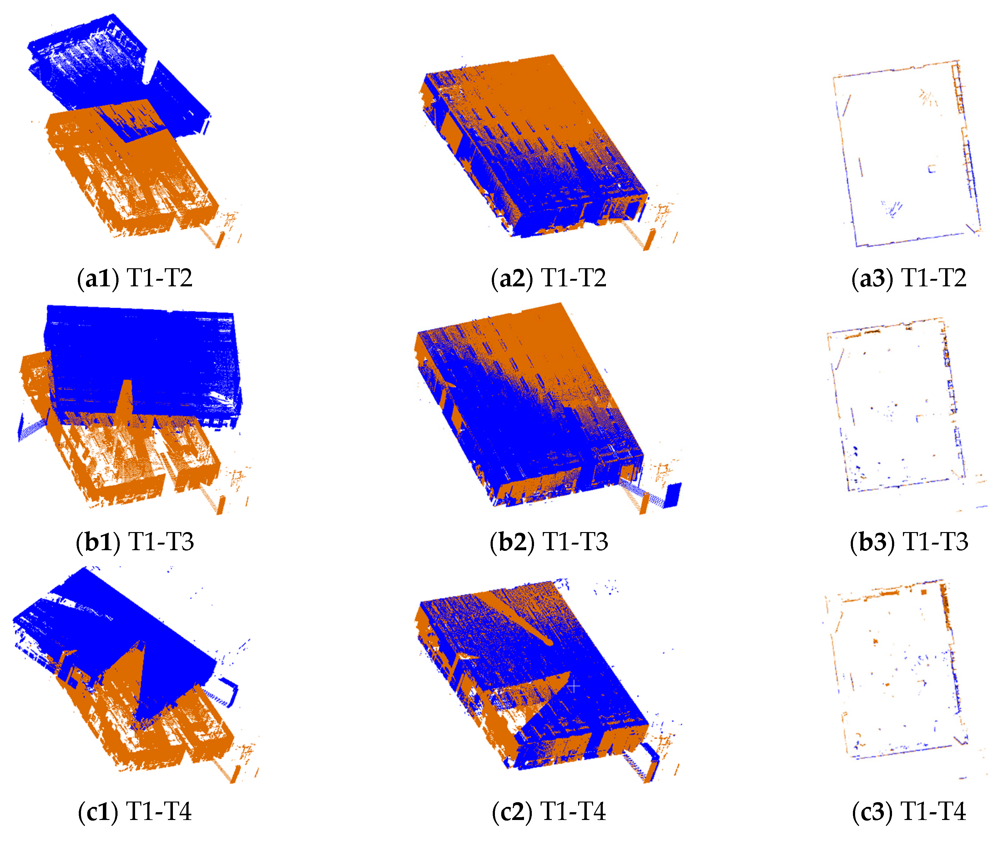
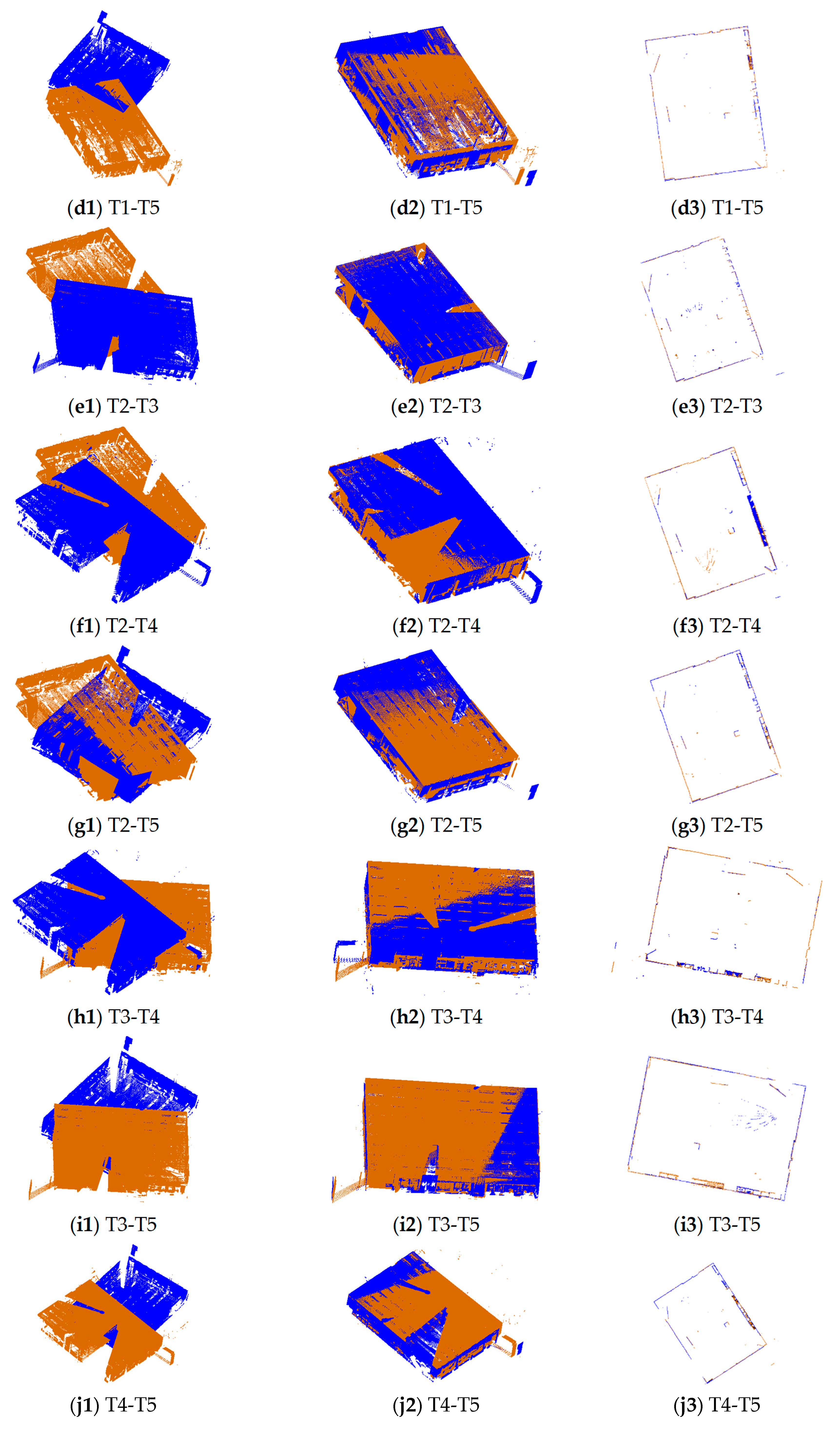
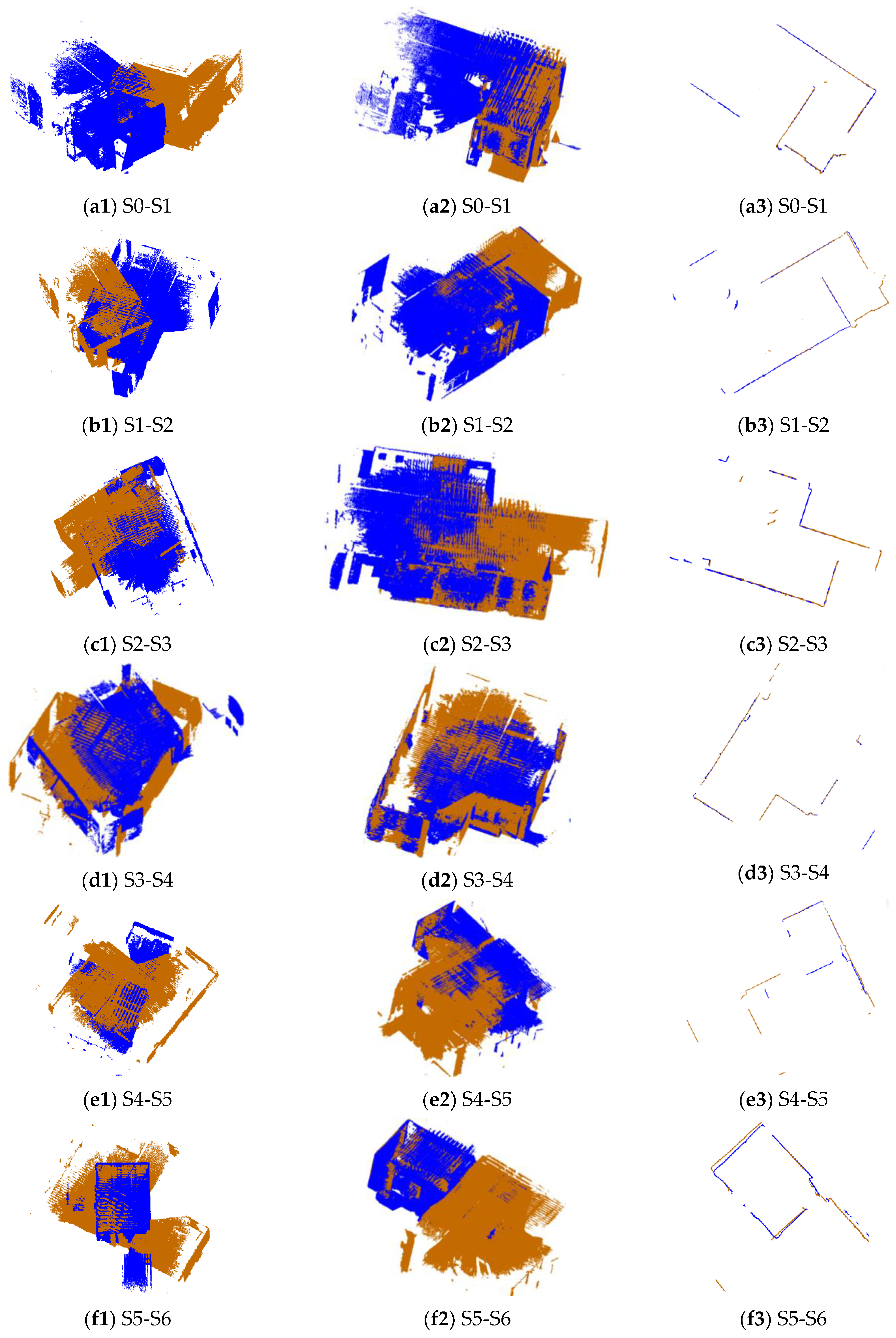
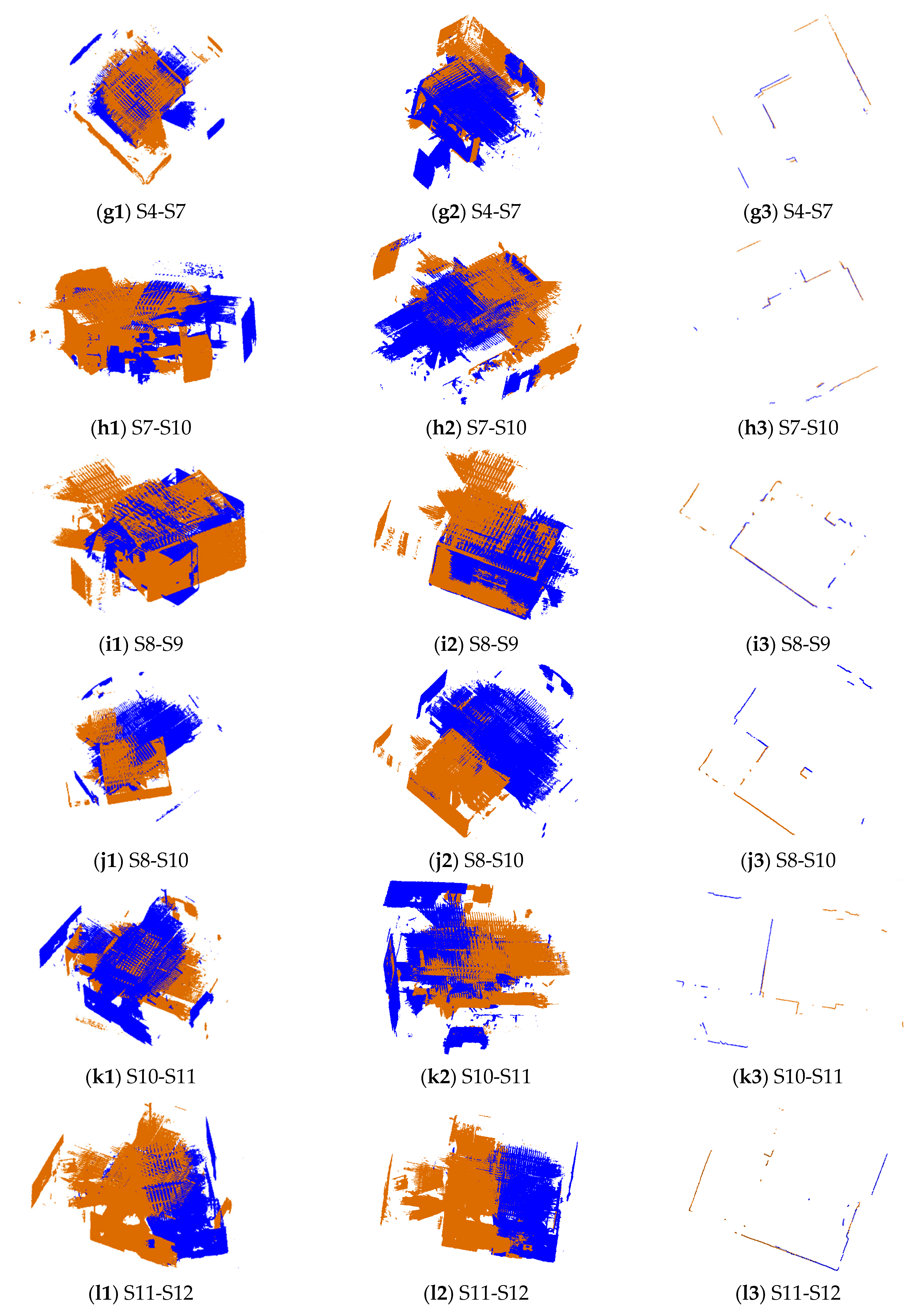
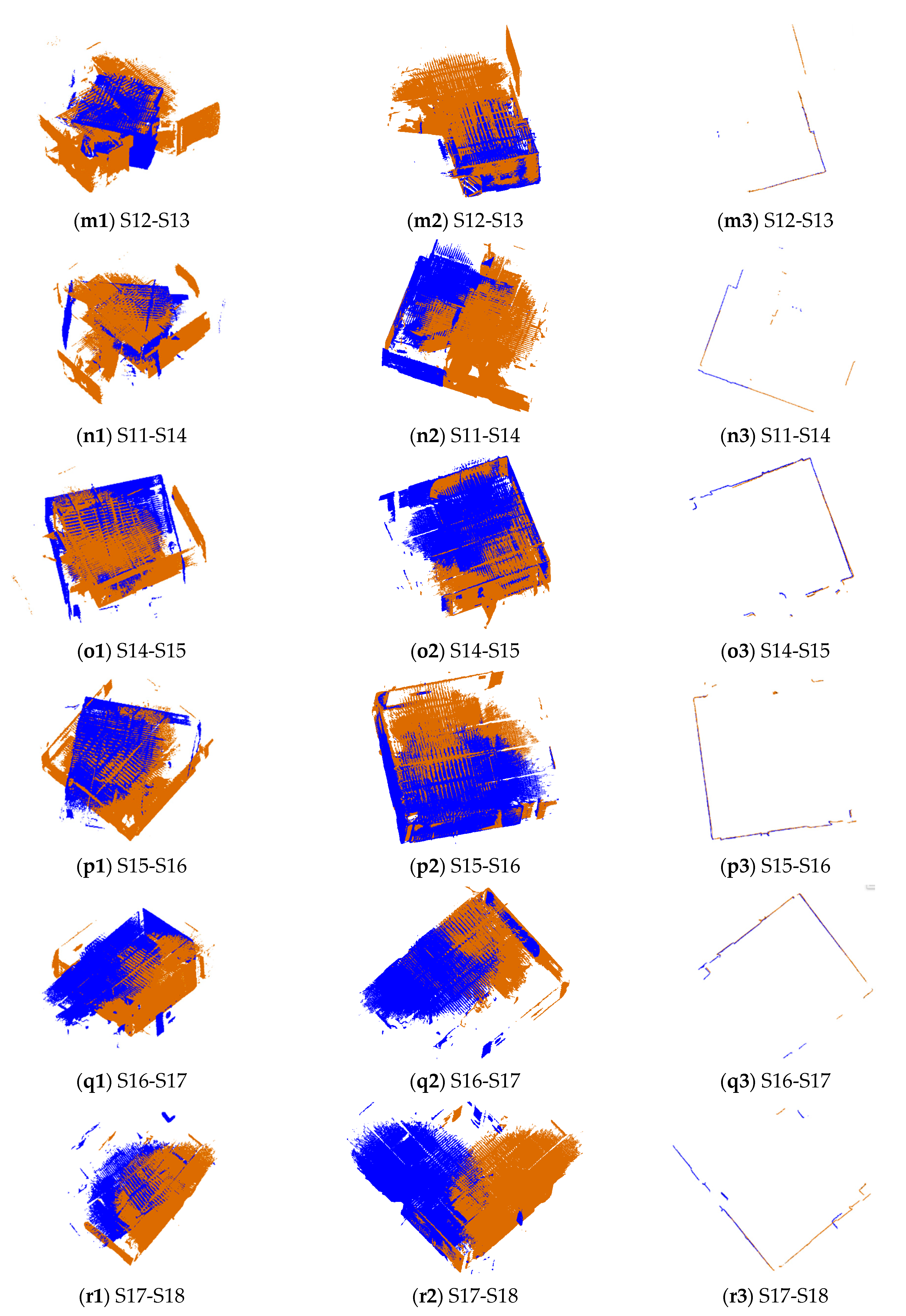
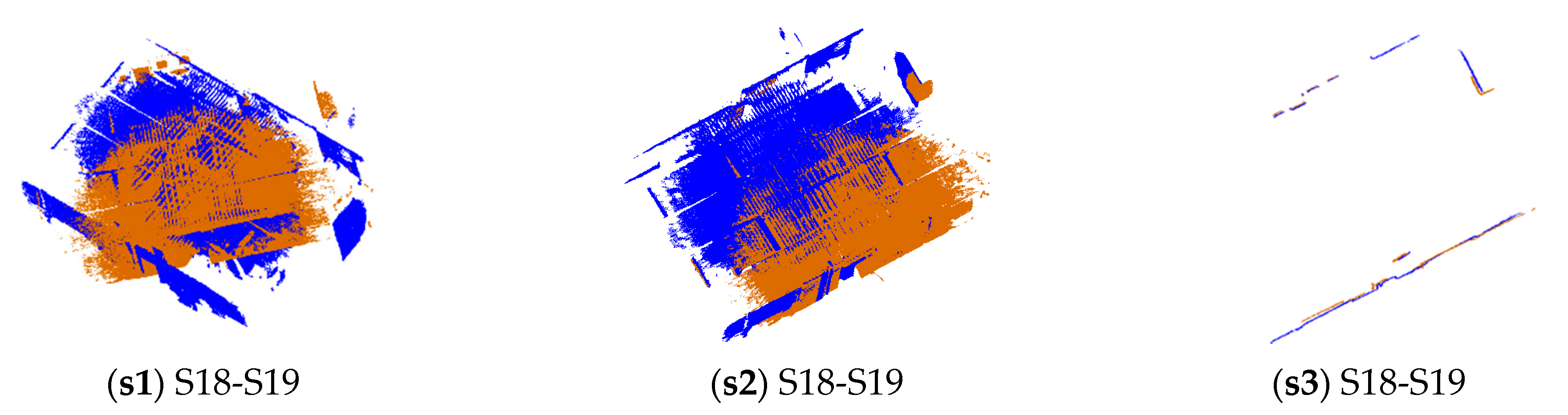
3.2. Qualitative Evaluations

The pairs of point clouds described in Section 2.1 were registered using the proposed 2D line feature-based method (named 2DLF in the following). The registration results of dataset SR and CB are shown in Figure 5 and Figure 6. The source and target points before registration, after registration, and the horizontal section view of the registered point clouds are shown in the first column, second column, and third column, respectively. The source points are colored in blue and the target points are colored in brown. It can be seen from the second and the third column of Figure 5 that all 10 pairs of points from dataset SR are well registered. There is no obvious misalignment in the horizontal section view. The scene of dataset CB is much more complicated. Due to the complexity of the scene and the similarity of indoor structures, it is hard to judge from Figure 6 whether a pair of point clouds is successfully registered or not. By carefully identification, we can see from Figure 6 that the point clouds between S0 and S1, S1 and S2, S2 and S3, S3 and S4, S7 and S10, S8 and S9, S8 and S10, S12 and S13, S14 and S15, S15 and S16, S16 and S17, and S18 and S19 are well registered. The pairs between S5 and S6 and S4 and S7 are successfully registered, but obvious misalignments can be seen in the results.

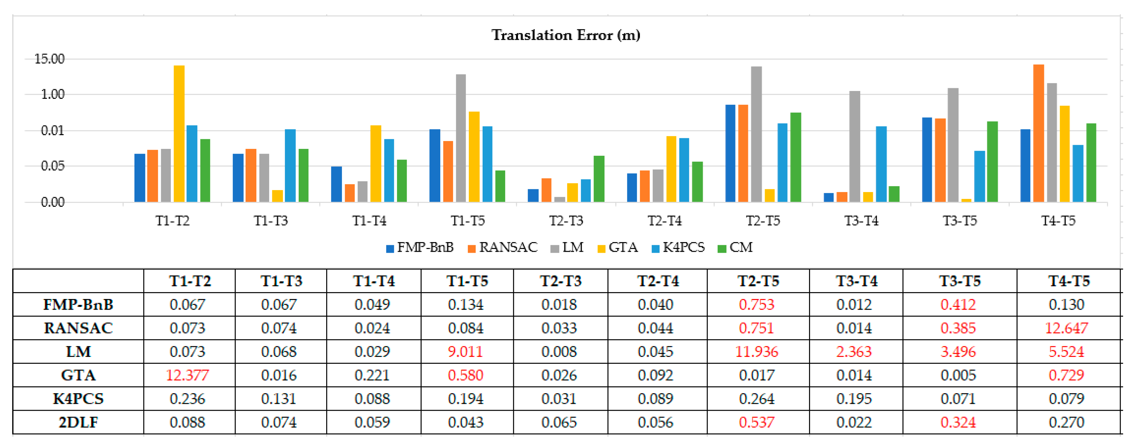
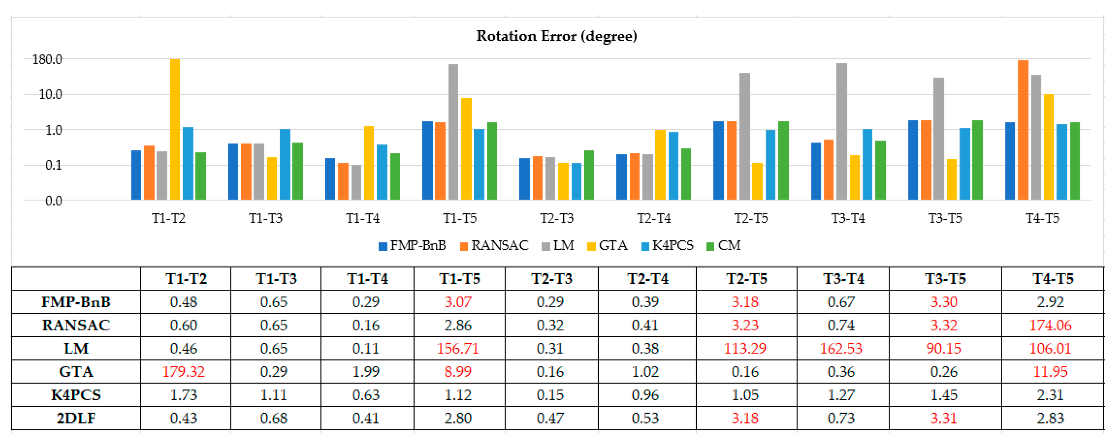
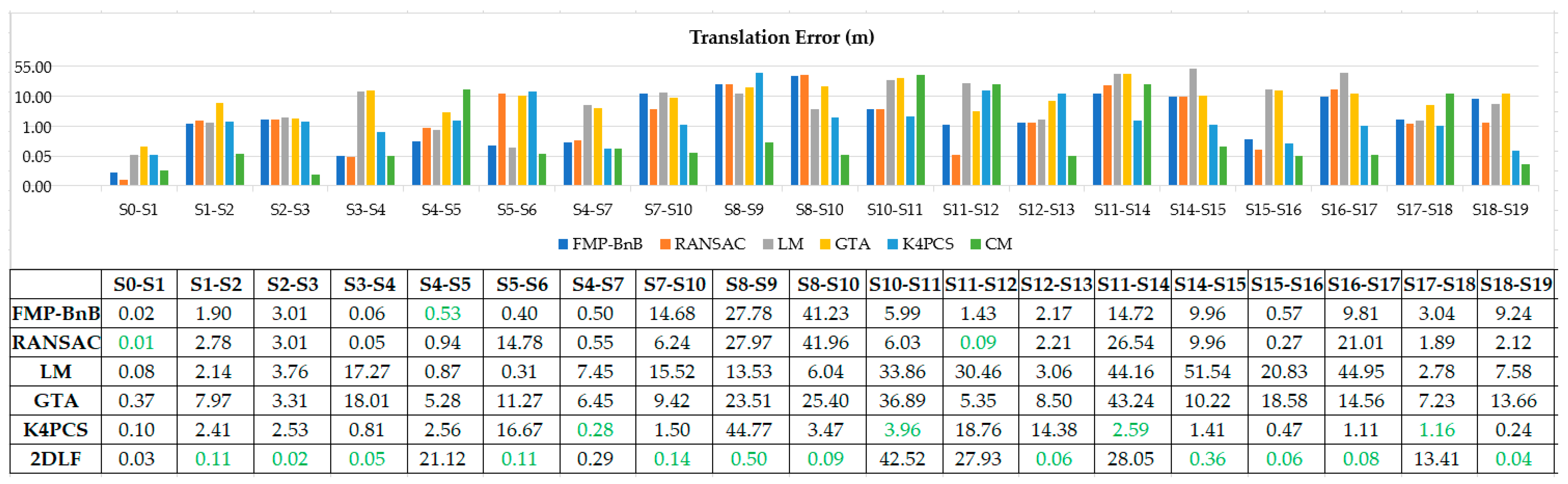
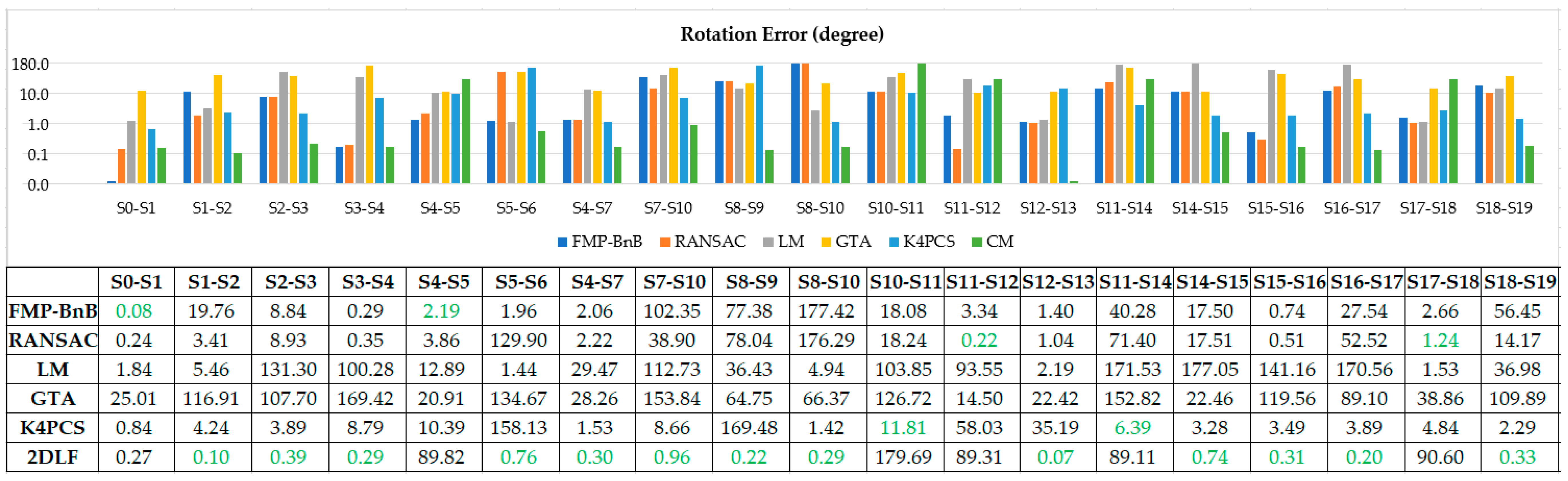
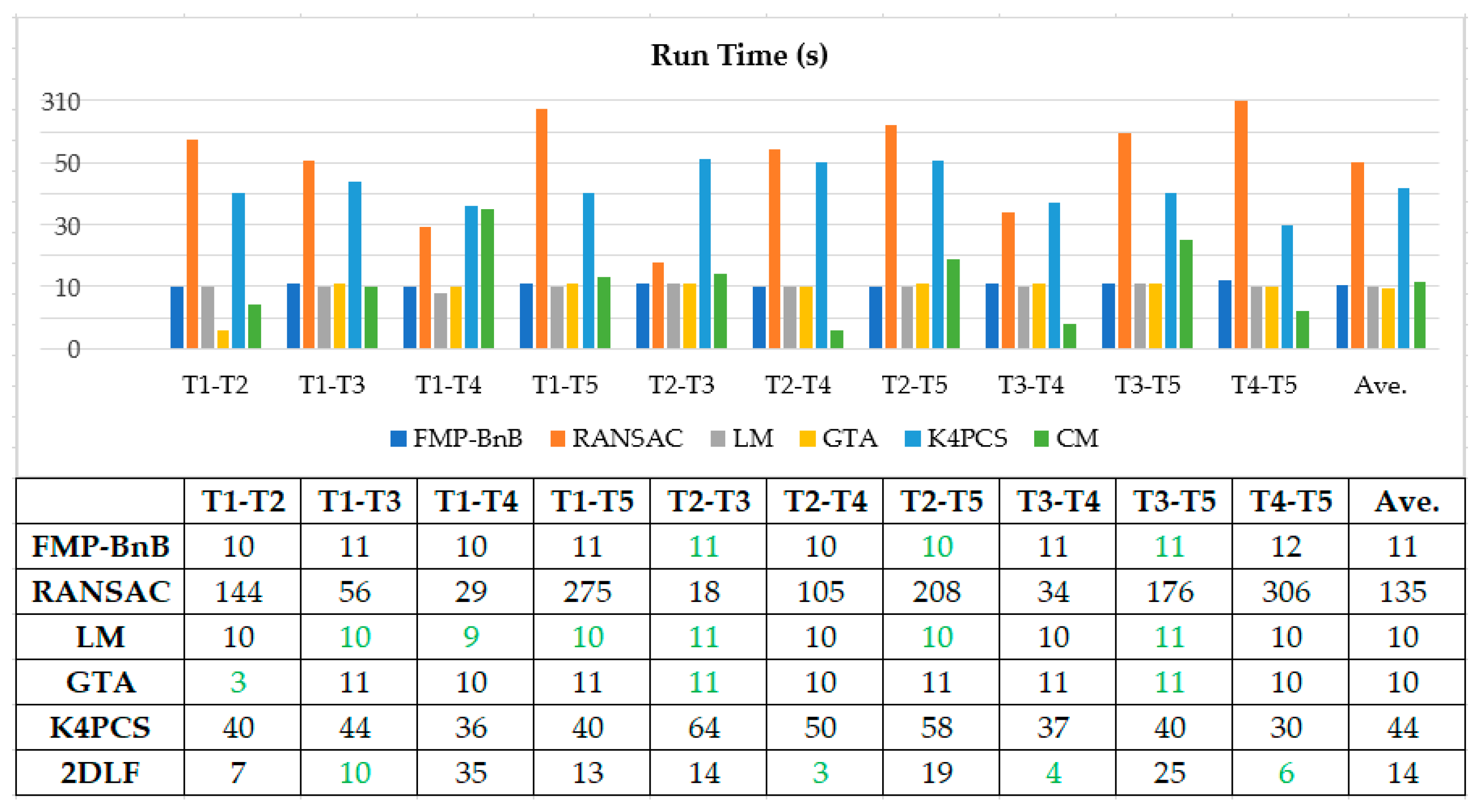
3.3. Quantitative Evaluations

The registration results of the 10 pairs of point clouds from dataset SR and the 19 pairs of point clouds from dataset CB were quantitatively evaluated using the metrics described in Section 3.1. In order to compare the proposed method to other state-of-the-art methods, the two datasets were also registered by the fast match pruning branch-and-bound (FMP-BnB) method [43], the 4DOF RANSAC method [49], the 4DOF version of the lifting method (LM) [50], the Game-Theory approach (GTA) method [51], and the keypoint-based 4PCS (K4PCS) method [34]. All the results were evaluated using the metrics described in Section 3.1.
Figure 7 and Figure 8 shows the translation error and rotation error of 10 pairs point clouds from dataset SR. The FMP-BnB method successfully registered seven pairs of point clouds (T1-T2, T1-T3, T1-T4, T2-T3, T2-T4, T3-T4, T4-T5), and the SRR was 70%. The RANSAC method successfully registered seven pairs of point clouds (T1-T2, T1-T3, T1-T4, T1-T5, T2-T3, T2-T4, T3-T4), and the SRR was 70%. The LM method successfully registered five pairs of point clouds (T1-T2, T1-T3, T1-T4, T2-T3, T2-T4), and the SRR was 50%. The GTA method successfully registered seven pairs of point clouds (T1-T3, T1-T4, T2-T3, T2-T4, T2-T5, T3-T4, T3-T5), and the SRR was 70%. The K4PCS method successfully registered all 10 pairs of point clouds, and the SRR was 100%. The proposed 2DLF method successfully registered eight pairs of point clouds (T1-T2, T1-T3, T1-T4, T1-T5, T2-T3, T2-T4, T3-T4, T4-T5), and the SRR was 80%. In dataset SR, the performance of the proposed 2DLF method was better than that of the FMP-BnB method, the RANSAC method, the LM method, and the GTA method.
Figure 9 and Figure 10 shows the translation error and rotation error of 19 pairs point clouds in dataset CB. The proposed 2DLF method achieved the best translation error in 12 (S1-S2, S2-S3, S3-S4, S5-S6, S7-S10, S8-S9, S8-S10, S12-S13, S14-S15, S15-S16, S16-S17, S18-S19) out of 19 pairs of point clouds. Besides this, the proposed 2DLF method achieved the best rotation error in 13 (S1-S2, S2-S3, S3-S4, S5-S6, S4-S7, S7-S10, S8-S9, S8-S10, S12-S13, S14-S15, S15-S16, S16-S17, S18-S19) out of 19 pairs of point clouds. The proposed 2DLF method achieved far more best error pairs both in terms of translation error and rotation error than the other five methods did. The FMP-BnB method successfully registered two pairs of point clouds (S0-S1, S3-S4) and the SRR was 10%. The RANSAC method successfully registered four pairs of point clouds (S0-S1, S3-S4, S11-S12, S15-S16) and the SRR was 21%. The LM method only successfully registered one pair of point clouds and the SRR was 5%. The GTA method failed to register any of the 19 pairs of point clouds. The K4PCS method successfully registered S0-S1, S4-S7, and S18-S19. The SRR was 16%. The proposed method successfully registered 12 pairs of point clouds (S0-S1, S1-S2, S2-S3, S3-S4, S5-S6, S4-S7, S7-S10, S8-S10, S12-S13, S15-S16, S16-S17, S18-S19) and the SRR was 63%. The proposed 2DLF method achieved the best SRR in dataset CB.
All the algorithms were implemented using C++ and ran on a desktop with an Intel® Core™ i7-9700K CPU and a 64 Gigabyte memory. The time to register each pair of point cloud was recorded. Figure 11 and Figure 12 demonstrates the time needed to register the pairs of point clouds in dataset SR and CB using the proposed 2DLF method and the comparison methods. It can be seen from Figure 11 that the proposed 2DLF method was the most time-efficient method in four pairs of point clouds, while the FMP-BnB method, the RANSAC method, the LM method, the GTA method, and the K4PCS method were the most efficient method in 3, 0, 6, 3, and 0 pairs of point clouds in dataset SR. It can be seen from Figure 12 that the FMP-BnB method, the RANSAC method, the LM method, the GTA method, the K4PCS method, and the 2DLF method were the most time-efficient method in 7, 0, 11, 11, 5, and 11 pairs of point clouds in dataset CB. Due to the lower point number in each station, it took less time to register the pairs of point clouds in CB than SR. It can be concluded that the proposed 2DLF method took a little bit more time than the FMP-BnB method, the LM method, and the GTA method, but was obviously more time-efficient than the RANSAC method and the K4PCS method.

4. Discussion

4.1. Accuracy and Time Efficiency

The proposed method achieved a comparable accuracy compared with the FMP-BnB method and the K4PCS method and a better accuracy compared with the RANSAC method, the LM method, and the GTA method in dataset SR. The successful registration rate is only lower than that of the K4PCS method and better than that of the RANSAC method and LM method in dataset SR. In dataset CB, the proposed method successfully registered the maximum number of pairs of point clouds, and the accuracy is better than that of the comparison methods.
Both in dataset SR and CB, the time efficiency of the proposed method is comparable with that of the FMP-BnB method, the LM method, and the GTA method, and it is more time-efficient than the RANSAC method and the K4PCS method. The time cost of the proposed method is mainly determined by two factors: (1) the number of line pairs to match and (2) the time efficiency of the line match result in the evaluation algorithm. To reduce the number of line pairs, the angle between the two lines is checked before matching. The line pair is directly abandoned if the angle between the two lines is smaller than the threshold. The match is skipped if the angles between two lines in the source ortho-projected image and the target ortho-projected image are significantly different. Finding the nearest point of the transformed source ortho-projected image in the target ortho-projected image is time-consuming. To make the line match result evaluation algorithm more time-efficient, a grid filtering can be applied to the source ortho-projected image and the target ortho-projected image to reduce the point number.

4.2. Limitations

When the point clouds that need to be registered are scanned in a closed room, the generated ortho-projected image may be a square or rectangle. In such situation, the matching between the source ortho-projected image and the target ortho-projected image may result in a wrong matching result. As illustrated in Figure 13a,b, the proposed method cannot distinguish these two situations and may lead to a wrong matching result. Fortunately, the indoor scenes often have doors and static objects (as illustrated in Figure 13c), and these doors and static objects can help us to avoid such ambiguity. The successful registration of dataset SR proved that the proposed method can successfully deal with such situations.
For point pairs with one scanned inside a room and one outside the room (for example, S11 and S12 in dataset CB), the registration may fail due to it being hard to find enough corresponding lines in the source and target ortho-projected images. Besides this, some pairs of point clouds scanned in large rooms may only exist one corresponding line due to the limited scanning distance of the used equipment, as illustrated in Figure 14a,b. The failed pairs of S4-S5, S8-S9, S10-S11, S11-S14, S14-S15, and S17-S18 belong to this case.

5. Conclusions

This paper proposes a 4DOF registration method to coarsely register pairwise indoor point clouds that takes full advantage of the knowledge that the equipment is levelled or the tilt compensated is by a built-in inclination sensor. The 4DOF registration was decomposed into horizontal alignment and vertical alignment. The horizontal alignment was achieved by the matching of point cloud generated by ortho-projected images. This paper proposed a new ortho-projected image generation method using points the between floor and ceiling and a new ortho image-matching method that uses 2D line features detected from source and target ortho-projected images. Besides this, this paper proposed to achieve vertical alignment using the height difference of the floor and ceiling between the source points and target points. Two datasets, one with five stations and the other with 20 stations, were used to evaluate the performance of the proposed method. The experimental results show that the proposed method achieved an 80% successful registration rate in a simple scene, which is better than the FMP-BnB method (70%), the RANSAC method (70%), the LM method (50%), and the GTA method (70%). The proposed method achieved a better successful registration rate (63%) in challenging scenes than the FMP-BnB method (10%), the RANSAC method (21%), the LM method (5%), the GTA method (0%), and the K4PCS method (16%). The proposed method was more time-efficient than the RANSAC method and the K4PCS method. Even though the proposed method still has some limitations in indoor point cloud registration, it provides an alternative to solve the indoor point cloud registration problem.
In this paper, ortho-projected images were generated using only vertical plane points. Due to occlusion and the limited scanning range, it may fail to find enough lines in the source and target ortho-projected images and thus fail to register the point clouds. In the future, all source and target points may be exploited to generate ortho-projected images to improve the robustness of the method.

Author Contributions

Conceptualization, Hua Liu; methodology, Zhen Li and Xiaoming Zhang; software, Junxiang Tan; validation, Zhen Li, Xiaoming Zhang, Junxiang Tan, and Hua Liu; formal analysis, Hua Liu; investigation, Zhen Li; resources, Zhen Li and Hua Liu; data curation, Hua Liu; writing—original draft preparation, Zhen Li; writing—review and editing, Xiaoming Zhang, Junxiang Tan, and Hua Liu; visualization, Junxiang Tan; supervision, Hua Liu; project administration, Hua Liu; funding acquisition, Zhen Li and Hua Liu. All authors have read and agreed to the published version of the manuscript.

Funding

This research was funded by the National Natural Science Foundation of China (grant number 41601488); the Natural Science Foundation of Jiangsu Province (grant number BK20160469); and the Open Fund of Key Laboratory for Digital Land and Resources of Jiangxi Province, East China University of Technology (grant number DLLJ202004).

Data Availability Statement

The dataset SR used in this paper is publicly available dataset and can be found here: https://ethz.ch/content/dam/ethz/special-interest/baug/igp/photogrammetry-remote-sensing-dam/documents/sourcecode-and-datasets/PascalTheiler/office.zip. The dataset CB used in this paper is available on request from the corresponding author. The dataset is not publicly available due to it is collected by a commercial company.

Acknowledgments

The authors thank ETH Zurich for making their dataset open accessible and Wuhan RGSpace Technology Co. LTD for providing the point cloud dataset.

Conflicts of Interest

The authors declare no conflict of interest.

References

  1. Iman Zolanvari, S.M.; Laefer, D.F. Slicing Method for curved façade and window extraction from point clouds. ISPRS J. Photogramm. 2016, 119, 334–346. [Google Scholar] [CrossRef]
  2. Liang, X.; Kankare, V.; Hyyppä, J.; Wang, Y.; Kukko, A.; Haggrén, H.; Yu, X.; Kaartinen, H.; Jaakkola, A.; Guan, F.; et al. Terrestrial laser scanning in forest inventories. ISPRS J. Photogramm. 2016. [Google Scholar] [CrossRef]
  3. Lague, D.; Brodu, N.; Leroux, J. Accurate 3D comparison of complex topography with terrestrial laser scanner: Application to the Rangitikei canyon (N-Z). ISPRS J. Photogramm. 2013, 82, 10–26. [Google Scholar] [CrossRef] [Green Version]
  4. Mahmood, B.; Han, S. 3D Registration of Indoor Point Clouds for Augmented Reality; American Society of Civil Engineer: Reston, VA, USA, 2019; pp. 1–8. [Google Scholar]
  5. Mahmood, B.; Han, S.; Lee, D. BIM-Based Registration and Localization of 3D Point Clouds of Indoor Scenes Using Geometric Features for Augmented Reality. Remote Sens. 2020, 12, 2302. [Google Scholar] [CrossRef]
  6. Bueno, M.; González-Jorge, H.; Martínez-Sánchez, J.; Lorenzo, H. Automatic point cloud coarse registration using geometric keypoint descriptors for indoor scenes. Automat. Constr. 2017, 81, 134–148. [Google Scholar] [CrossRef]
  7. Li, F.; Zlatanova, S.; Koopman, M.; Bai, X.; Diakité, A. Universal path planning for an indoor drone. Automat. Constr. 2018, 95, 275–283. [Google Scholar] [CrossRef]
  8. Ochmann, S.; Vock, R.; Wessel, R.; Klein, R. Automatic reconstruction of parametric building models from indoor point clouds. Comput. Graph. 2016, 54, 94–103. [Google Scholar] [CrossRef] [Green Version]
  9. Shi, W.; Ahmed, W.; Li, N.; Fan, W.; Xiang, H.; Wang, M. Semantic Geometric Modelling of Unstructured Indoor Point Cloud. ISPRS Int. J. Geo-Inf. 2019, 8, 9. [Google Scholar] [CrossRef] [Green Version]
  10. Navvis. Unleash the Power of Digital Buildings. Available online: https://www.navvis.com/ (accessed on 17 September 2020).
  11. Introducing the Intel RealSense LiDAR Camera L515. Available online: https://www.intel.com/content/www/us/en/architecture-and-technology/realsense-overview.html (accessed on 17 September 2020).
  12. Kinect for Windows. Available online: https://developer.microsoft.com/en-us/windows/kinect/ (accessed on 17 September 2020).
  13. Besl, P.J.; McKay, N.D. A method for registration of 3-D shapes. IEEE Trans. Pattern Anal. 1992, 14, 239–256. [Google Scholar] [CrossRef]
  14. Rusinkiewicz, S.; Levoy, M. Efficient variants of the ICP algorithm. In Proceedings of the Third International Conference on 3-D Digital Imaging and Modeling, Quebec City, QC, Canada, 28 May–1 June 2001; pp. 145–152. [Google Scholar]
  15. Han, J.; Yin, P.; He, Y.; Gu, F. Enhanced ICP for the Registration of Large-Scale 3D Environment Models: An Experimental Study. Sensors 2016, 16, 228. [Google Scholar] [CrossRef]
  16. Biber, P.; Stra Ss Er, W. The normal distributions transform: A new approach to laser scan matching. In Proceedings of the 2003 IEEE/RSJ International Conference on Intelligent Robots and Systems (IROS 2003) (Cat. No. 03CH37453), Las Vegas, NV, USA, 27–31 October 2003; pp. 2743–2748. [Google Scholar]
  17. Takeuchi, E.; Tsubouchi, T. A 3-D scan matching using improved 3-D normal distributions transform for mobile robotic mapping. In Proceedings of the 2006 IEEE/RSJ International Conference on Intelligent Robots and Systems, Beijing, China, 9–15 October 2006; pp. 3068–3073. [Google Scholar]
  18. Magnusson, M. The Three-Dimensional Normal-Distributions Transform: An Efficient Representation for Registration, Surface Analysis, and Loop Detection. Ph.D. Thesis, Örebro Universitet, Örebro, Sweden, 2009. [Google Scholar]
  19. Johnson, A.E.; Hebert, M. Using spin images for efficient object recognition in cluttered 3D scenes. IEEE Trans. Pattern Anal. 1999, 21, 433–449. [Google Scholar] [CrossRef] [Green Version]
  20. Makadia, A.; Patterson, A.; Daniilidis, K. Fully Automatic Registration of 3D Point Clouds. In Proceedings of the 2006 IEEE Computer Society Conference on Computer Vision and Pattern Recognition (CVPR’06), New York, NY, USA, 17–22 June 2006; pp. 1297–1304. [Google Scholar]
  21. Rusu, R.B.; Blodow, N.; Marton, Z.C.; Beetz, M. Aligning point cloud views using persistent feature histograms. In Proceedings of the IEEE/RSJ International Conference on Intelligent Robots and Systems, Nice, France, 22–26 September 2008; pp. 3384–3391. [Google Scholar]
  22. Rusu, R.B.; Blodow, N.; Beetz, M. Fast point feature histograms (FPFH) for 3D registration. In Proceedings of the IEEE International Conference on Robotics and Automation, Kobe, Japan, 12–17 May 2009; pp. 3212–3217. [Google Scholar]
  23. Dong, Z.; Yang, B.; Liu, Y.; Liang, F.; Li, B.; Zang, Y. A novel binary shape context for 3D local surface description. ISPRS J. Photogramm. 2017, 130, 431–452. [Google Scholar] [CrossRef]
  24. Yang, B.; Zang, Y. Automated registration of dense terrestrial laser-scanning point clouds using curves. ISPRS J. Photogramm. 2014, 95, 109–121. [Google Scholar] [CrossRef]
  25. Dold, C.; Brenner, C. Registration of terrestrial laser scanning data using planar patches and image data. Int. Arch. Photogramm. Remote Sens. Spat. Inf. Sci.-ISPRS Arch. 2006, 36, 78–83. [Google Scholar]
  26. Kelbe, D.; van Aardt, J.; Romanczyk, P.; van Leeuwen, M.; Cawse-Nicholson, K. Marker-Free Registration of Forest Terrestrial Laser Scanner Data Pairs With Embedded Confidence Metrics. IEEE Trans. Geosci. Remote 2016, 54, 4314–4330. [Google Scholar] [CrossRef]
  27. Zeng, A.; Song, S.; Nießner, M.; Fisher, M.; Xiao, J.; Funkhouser, T. 3dmatch: Learning local geometric descriptors from rgb-d reconstructions. In Proceedings of the IEEE Conference on Computer Vision and Pattern Recognition (CVPR), Hulunono, HI, USA, 21–26 July 2017; pp. 1802–1811. [Google Scholar]
  28. Zhang, Z.; Sun, L.; Zhong, R.; Chen, D.; Xu, Z.; Wang, C.; Qin, C.; Sun, H.; Li, R. 3-D Deep Feature Construction for Mobile Laser Scanning Point Cloud Registration. IEEE Geosci. Remote Sens. Lett. 2019, 16, 1904–1908. [Google Scholar] [CrossRef]
  29. Pujol-Miro, A.; Casas, J.R.; Ruiz-Hidalgo, J. Correspondence matching in unorganized 3D point clouds using Convolutional Neural Networks. Image Vision Comput. 2019, 83, 51–60. [Google Scholar] [CrossRef]
  30. Qi, C.R.; Su, H.; Mo, K.; Guibas, L.J. PointNet: Deep Learning on Point Sets for 3D Classification and Segmentation. arXiv 2017, arXiv:1612.00593v2. [Google Scholar]
  31. Deng, H.; Birdal, T.; Ilic, S. PPFNet: Global Context Aware Local Features for Robust 3D Point Matching. In Proceedings of the 2018 IEEE/CVF Conference on Computer Vision and Pattern Recognition, Salt Lake City, UT, USA, 18–23 June 2018; pp. 195–205. [Google Scholar]
  32. Aoki, Y.; Goforth, H.; Srivatsan, R.A.; Lucey, S. PointNetLK: Robust & Efficient Point Cloud Registration using PointNet. In Proceedings of the IEEE/CVF Conference on Computer Vision and Pattern Recognition (CVPR), Long Beach, CA, USA, 16–20 June 2019; pp. 7163–7172. [Google Scholar]
  33. Mellado, N.; Aiger, D.; Mitra, N.J. SUPER 4PCS Fast Global Pointcloud Registration via Smart Indexing. Comput. Graph. Forum 2014, 33, 205–215. [Google Scholar] [CrossRef] [Green Version]
  34. Theiler, P.W.; Wegner, J.D.; Schindler, K. Keypoint-based 4-Points Congruent Sets—Automated marker-less registration of laser scans. ISPRS J. Photogramm. 2014, 96, 149–163. [Google Scholar] [CrossRef]
  35. Ge, X. Automatic markerless registration of point clouds with semantic-keypoint-based 4-points congruent sets. ISPRS J. Photogramm. 2017, 130, 344–357. [Google Scholar] [CrossRef] [Green Version]
  36. Järemo Lawin, F.; Danelljan, M.; Shahbaz Khan, F.; Forssén, P.; Felsberg, M. Density adaptive point set registration. In Proceedings of the IEEE Conference on Computer Vision and Pattern Recognition (CVPR), Salt Lake City, UT, USA, 18–22 June 2018; pp. 3829–3837. [Google Scholar]
  37. Tsin, Y.; Kanade, T. A Correlation-Based Approach to Robust Point Set Registration; Springer: Berlin/Heidelberg, Germany, 2004; pp. 558–569. [Google Scholar]
  38. Jian, B.; Vemuri, B.C. Robust point set registration using gaussian mixture models. IEEE Trans. Pattern Anal. 2010, 33, 1633–1645. [Google Scholar] [CrossRef] [PubMed]
  39. Myronenko, A.; Song, X. Point set registration: Coherent point drift. IEEE Trans. Pattern Anal. 2010, 32, 2262–2275. [Google Scholar] [CrossRef] [PubMed] [Green Version]
  40. Tsai, C.; Huang, C.; Chi-Yi, T.; Chih-Hung, H. Indoor Scene Point Cloud Registration Algorithm Based on RGB-D Camera Calibration. Sensors 2017, 17, 1874. [Google Scholar] [CrossRef] [Green Version]
  41. Sanchez, J.; Denis, F.; Checchin, P.; Dupont, F.; Trassoudaine, L. Global Registration of 3D LiDAR Point Clouds Based on Scene Features: Application to Structured Environments. Remote Sens. 2017, 9, 1014. [Google Scholar] [CrossRef] [Green Version]
  42. Pavan, N.L.; Dos Santos, D.R.; Khoshelham, K. Global Registration of Terrestrial Laser Scanner Point Clouds Using Plane-to-Plane Correspondences. Remote Sens. 2020, 12, 1127. [Google Scholar] [CrossRef] [Green Version]
  43. Cai, Z.; Chin, T.; Bustos, A.P.; Schindler, K. Practical optimal registration of terrestrial LiDAR scan pairs. ISPRS J. Photogramm. 2019, 147, 118–131. [Google Scholar] [CrossRef] [Green Version]
  44. Liu, H.; Zhang, X.; Xu, Y.; Chen, X. Efficient Coarse Registration of Pairwise TLS Point Clouds Using Ortho Projected Feature Images. ISPRS Int. J. Geo-Inf. 2020, 9, 255. [Google Scholar] [CrossRef]
  45. Ge, X.; Hu, H. Object-based incremental registration of terrestrial point clouds in an urban environment. ISPRS J. Photogramm. 2020, 161, 218–232. [Google Scholar] [CrossRef]
  46. Zhang, T.Y.; Suen, C.Y. A fast parallel algorithm for thinning digital patterns. Commun. ACM 1984, 27, 236–239. [Google Scholar] [CrossRef]
  47. Matasyx, J.; Kittlery, C.G.J. Progressive probabilistic Hough transform. In Proceedings of the British Machine Vision Conference, Southampton, UK, 14–17 September 1998; pp. 26.1–26.10. [Google Scholar]
  48. Dong, Z.; Liang, F.; Yang, B.; Xu, Y.; Zang, Y.; Li, J.; Wang, Y.; Dai, W.; Fan, H.; Hyyppä, J.; et al. Registration of large-scale terrestrial laser scanner point clouds: A review and benchmark. ISPRS J. Photogramm. 2020, 163, 327–342. [Google Scholar] [CrossRef]
  49. Fischler, M.A.; Bolles, R.C. Random sample consensus: A paradigm for model fitting with applications to image analysis and automated cartography. Commun. ACM 1981, 24, 381–395. [Google Scholar] [CrossRef]
  50. Zhou, Q.; Park, J.; Koltun, V. Fast Global Registration; Springer: Berlin/Heidelberg, Germany, 2016; pp. 766–782. [Google Scholar]
  51. Albarelli, A.; Rodolà, E.; Torsello, A. A game-theoretic approach to fine surface registration without initial motion estimation. In Proceedings of the 2010 IEEE Computer Society Conference on Computer Vision and Pattern Recognition, San Francisco, CA, USA, 13–18 June 2010; pp. 430–437. [Google Scholar]
Figure 1. The scan location of the experimental datasets. (a) scan locations of dataset SR; (b) scan locations of dataset CB.
Ijgi 10 00026 g001
Figure 2. Overview of the proposed 4 degrees of freedom (4DOF) indoor point cloud registration method.
Ijgi 10 00026 g002
Figure 3. The height histogram of a station indoor point cloud.
Ijgi 10 00026 g003
Figure 4. Two solutions for pair line matching. (a) Two lines in the source ortho-projected image, (b) two corresponding lines in the target ortho-projected image, (c) matching solution 1, (d) matching solution 2.
Ijgi 10 00026 g004
Figure 5. The registration results of 10 pairs of point clouds in dataset SR. The first column is the point clouds before registration, the second column is the point clouds after registration using the proposed method, and the third column is the horizontal section view of the point clouds after registration. The brown points are target points and the blue points are source points.
Ijgi 10 00026 g005aIjgi 10 00026 g005b
Figure 6. The registration results of 19 pairs of point clouds in dataset CB. The first column is the point clouds before registration, the second column is the point clouds after registration using the proposed method, and the third column is the horizontal section view of the point clouds after registration. The brown points are target points and the blue points are source points.
Ijgi 10 00026 g006aIjgi 10 00026 g006bIjgi 10 00026 g006cIjgi 10 00026 g006d
Figure 7. Translation error of pairs from dataset SR (the failed pairs are colored in red).
Ijgi 10 00026 g007
Figure 8. Rotation error of point cloud pairs from dataset SR (the failed pairs are colored in red).
Ijgi 10 00026 g008
Figure 9. Translation error of point cloud pairs from dataset CB (the best result of each pair is colored in green).
Ijgi 10 00026 g009
Figure 10. Rotation error of point cloud pairs from dataset CB (the best result of each pair is colored in green).
Ijgi 10 00026 g010
Figure 11. Run time to register point cloud pairs from dataset SR (the most time-efficient method for each pair is colored in green).
Ijgi 10 00026 g011
Figure 12. Run time to register point cloud pairs from dataset CB (the most time-efficient method for each pair is colored in green).
Ijgi 10 00026 g012
Figure 13. Ambiguity situations in line-based ortho-projected image matching. (a) ortho projected image of a rectangle room; (b) ambiguity situation of (a); (c) doors and static objects in the room.
Ijgi 10 00026 g013
Figure 14. Case where the source and target ortho-projected images only have one corresponding line due to the limited scanning distance. (a) Target ortho-projected image generated from S17 in CB; (b) source ortho-projected image generated from S18 in CB. The lines inside the red circle are corresponding walls.
Ijgi 10 00026 g014
Table 1. Summary of the experimental datasets.
DatasetDescriptionAbbr.#Scans#PointsUsed PairsDimensions (m)
1Simple Big Office RoomSR5T110720371T1-T2 T1-T316 × 11 × 3
T210707764T1-T4 T1-T5
T310729371T2-T3 T2-T4
T410694987T2-T5 T3-T4
T510753198T3-T5 T4-T5
2Complex Office Space with Multiple RoomsCB20S06071466S0-S1
S1-S2
S2-S3
S3-S4
S4-S5
S5-S6
S4-S7
S7-S10
S8-S9
S8-S10
S10-S11
S11-S12
S12-S13
S11-S14
S14-S15
S15-S16
S16-S17
S17-S18
S18-S19
18 × 11 × 2.7
S16054560
S25877122
S35593724
S45847040
S55964762
S66028178
S75475755
S85103696
S95302832
S105038474
S114990545
S124812543
S135631427
S145182758
S155542010
S165746671
S175851471
S185665512
S195482208
Publisher’s Note: MDPI stays neutral with regard to jurisdictional claims in published maps and institutional affiliations.

