Article

Rotational Workspace Expansion of a Planar CDPR with a Circular End-Effector Mechanism Allowing Passive Reconfiguration

by
Marco Alexander Carpio Alemán
1,2,*,
Roque Saltaren
2,
Alejandro Rodriguez
2,
Gerardo Portilla
2 and
Juan Diego Placencia
1
1
Centro de Automática y Robótica, Universidad Politécnica de Madrid, C/José Gutiérrez Abascal 2, 28006 Madrid, Spain
2
Grupo de Investigación en Interacción Robótica y Automática (GIIRA), Universidad Politécnica Salesiana, Calle Turuhuayco 3-69 y Calle Vieja, 010105 Cuenca, Ecuador
*
Author to whom correspondence should be addressed.
Robotics 2019, 8(3), 57; https://doi.org/10.3390/robotics8030057
Submission received: 7 June 2019 / Revised: 15 July 2019 / Accepted: 17 July 2019 / Published: 19 July 2019
(This article belongs to the Section Industrial Robots and Automation)

Abstract

:
Cable-Driven Parallel Robots (CDPR) operate over a large positional workspace and a relatively large orientation workspace. In the present work, the expansion of the orientation Wrench Feasible Workspace (WFW) in a planar four-cable passive reconfigurable parallel robot with three degrees of freedom was determined. To this end, we proposed a circular-geometry effector mechanism, whose structure allows automatic mobility of the two anchor points of the cables supporting the End Effector (EE). The WFW of the proposed circular structure robot was compared with that of a traditional robot with a rectangular geometry and fixed anchor points. Considering the feasible geometric and tension forces on the cables, the generated workspace volume of the robot was demonstrated in an analysis-by-intervals. The results were validated by simulating the orientation movements of the robot in ADAMS software and a real experimental test was developed for a hypothetical case. The proposed design significantly expanded the orientation workspace of the robot. The remaining limitation is the segment of the travel space in which the mobile connection points can slide. Overcoming this limitation would enable the maximum rotation of the EE.

1. Introduction

The workspace restricts the controller actions and mechanical movements of a robot, avoiding collisions between the various robot components and between the robot and its work environment. Therefore, determining and analyzing the workspace are essential components of robotics research [1].
Cable-driven parallel robots (CDPRs) have been recently deployed in industrial applications and rehabilitation programs for ill people. Merlet and Daney [2] proposed a fully autonomous portable mechanism for rescue operations. Various rehabilitation robots [3,4,5,6] rely on the correct orientation of the robot. Other examples can be found in space exploration, which is an environment where the manual setup of cable robots by human operators is typically not possible [7,8].
Most parallel robots are redundant, that is, the number of cables exceeds the number of degrees of freedom (DoF). Mathematical models of parallel robots can be solved using various techniques, which are broadly divisible into linear [9] and nonlinear programming. The workspace can be determined by analytical solutions and analysis-by-intervals [10,11,12]. However, when obtaining the wrench-feasible workspace (WFW) in a redundant system, these techniques incur a long calculation time [10].
The tensions exerted by the cables must also be limited in parallel robots. The authors of Reference [13] calculated the variables of interest for sizing the mechanical components of a robot prior to its construction. The authors of References [14,15] investigated the mechanical characteristics of polymer and elastic active cables in parallel robots, respectively. Although these cables can expand the workspace of the robot, they reduce the positioning accuracy of the EE.
The workspace of a parallel robot is diminished when the cables collide with the structure of the EE. Wang et al. [16] determined the workspace of a planar robot with collision and object avoidance in an algorithm that scans the cables and computes the range of the allowed movements.
As parallel robots are engaged in multiple applications, improving their performance by optimizing their geometric characteristics and dimensions of their forces is essential. In Reference [17], the orientation workspace was increased by mobilizing the support bases of the cables in the robot configuration. Rodriguez–Barroso et al. [18] adapted the robot’s workspace to different tasks by reconfiguring the EE. Duan et al. [19] incorporated springs in the robot’s structure and analyzed their effects on the workspace. They reported that the gained WFW depends on the design parameters. Noting that most CDPR studies assume a fixed structure of the cable links, Gagliardini et al. [20] designed reconfigurable anchor points based on the desired trajectory, their design is called reconfigurable CDPR. Barbazza et al. [21] proposed a reconfigurable end-effector for industrial operations where cables are reconfigured in each stage to avoid collisions and a planned trajectory to minimize reconfiguration times. Nguyen et al. [22] studied a larger reconfigurable robot for transporting personnel in an airplane maintenance shop, taking into consideration the top limit of displacement of the mobile platform and the increase of energy usage due to the tensions on the cables. Pott et al. [23] suggested a method to determine the space taken by the cables when the robot is moving, considering that the cable trajectory takes the form of a cone. In References [24,25] the authors analyzed several typical configurations of a modular reconfigurable cable-driven parallel robot. Finally, in Reference [26] the author presented a study of the advantages of reconfigurable platforms in parallel robots and suggested a new method for dealing with the constrains in the kinematic coupling of limbs.
To develop the existing research on a reconfigurable CDPR workspace expansion, this article proposes a novel end-effector mechanism that allows an automatic or passive reconfiguration. Three cases are analyzed: One using a classical rectangular EE, and two using the proposed circular EE. This work addresses a kinematic and geometric analysis, leaving the dynamic analysis for future work.

2. Description of End Effectors

Despite the wide-range research on the applications and WFW analysis of CDPRs, the orientation workspace has been less well studied than the positional workspace. The present study determines the orientation workspace of a 3-DoF reconfigurable passive planar CDPR due to its circular-geometry mechanism of the EE with freely movable anchor points.
The workspace of the reconfigurable passive planar CDPR in a vertical plane is analyzed for end effectors with classical rectangular geometry and the proposed with circular geometry, leading to the following different cases:
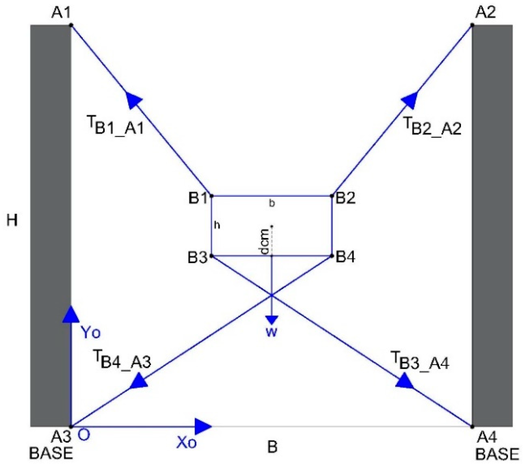
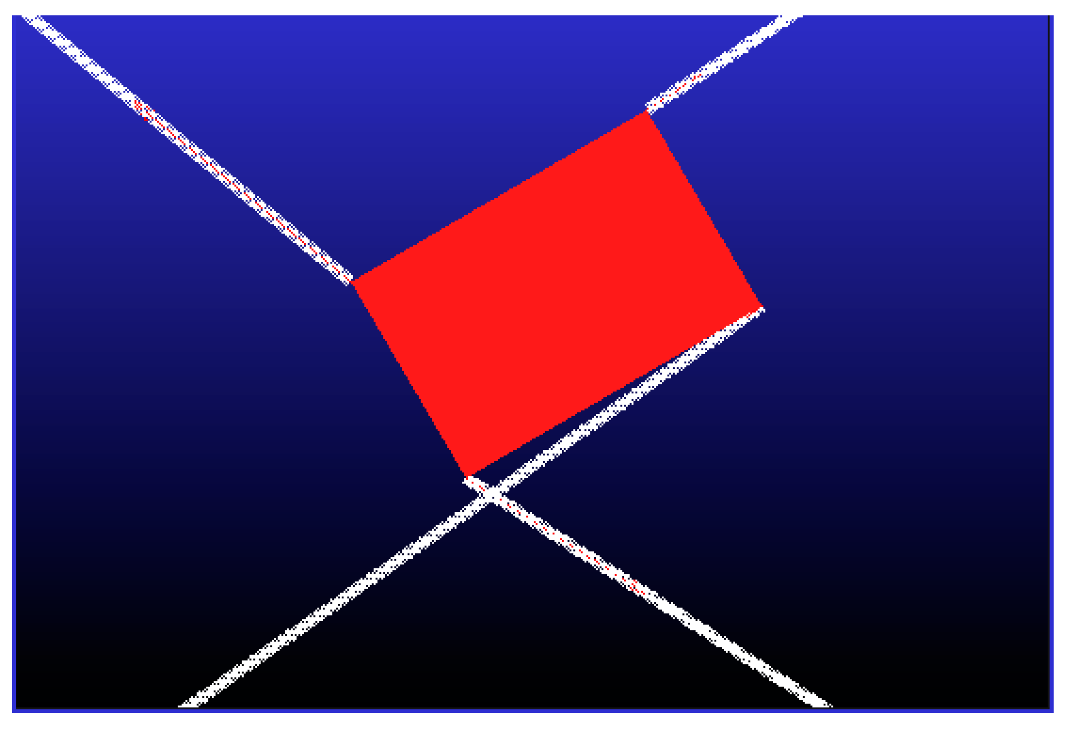
  • Case 1: A four-cable planar CDPR with 3-DoF and an EE with rectangular geometry where cables are attached at fixed anchor points on the EE. In this configuration, the cables cannot collide with the EE during a rotation, so the only forces acting on the cables are tension forces. Figure 1 shows the EE with the classical rectangular geometry, where the measurements of the mobile structure are:
    • H = 0.2 m and b = 0.3 m, respectively.
    • W = 50 N, is the weight of the EE.
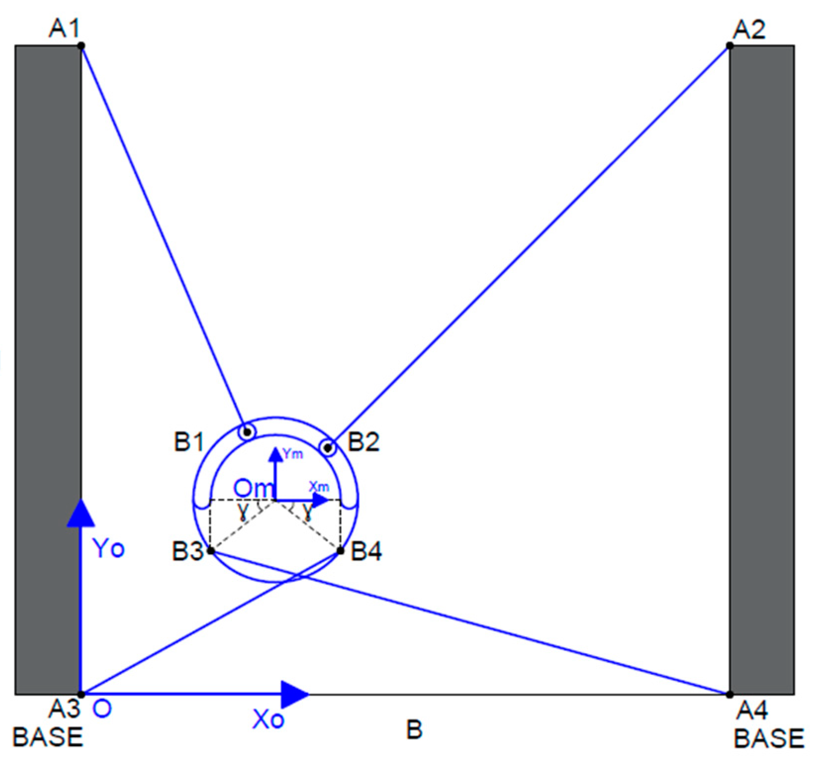
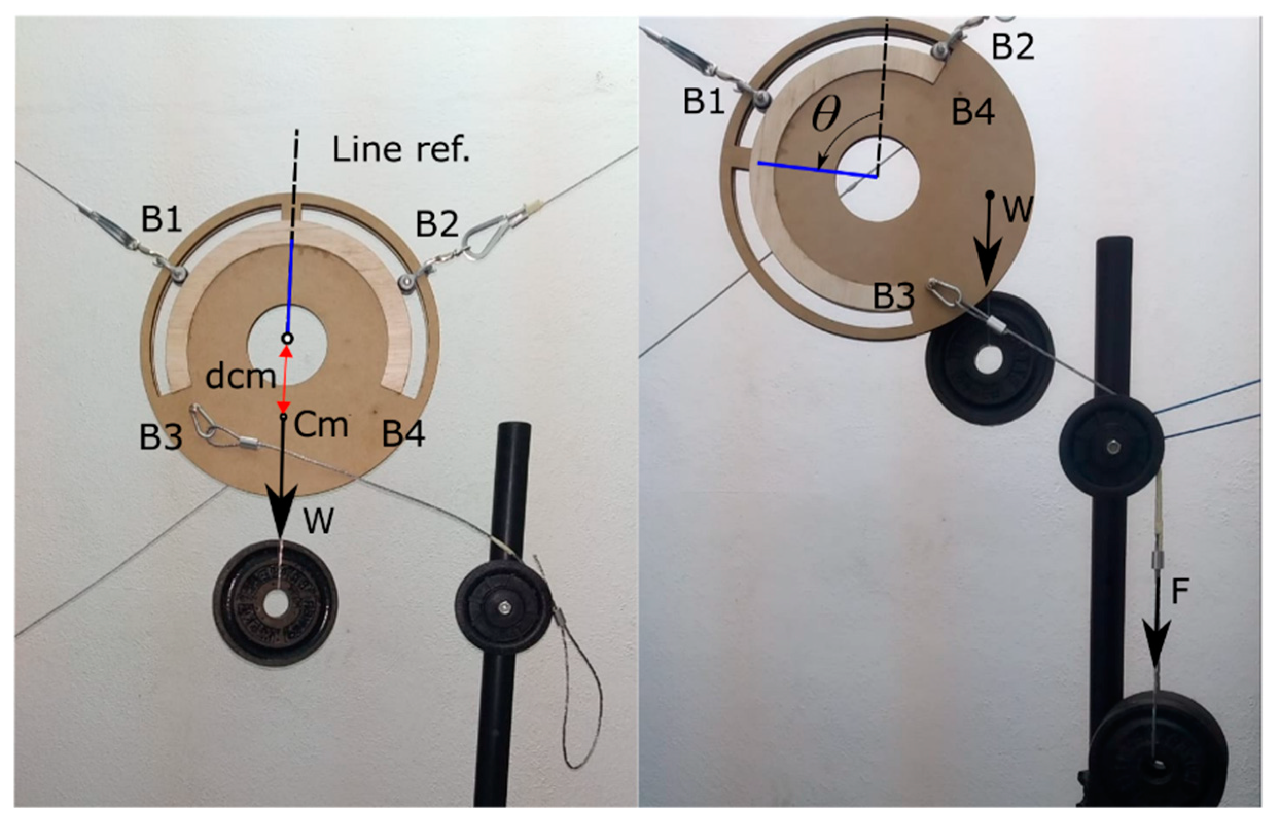
  • Case 2: A passive reconfigurable four-cable planar CDPR with 3-DoF and an EE with circular geometry where cable-connection points supporting the robot can move freely around the circular periphery mechanism, so the orienting effect is linked only to the two fixed anchored cables at the lower side. In Figure 2, the geometry of this EE is depicted, where its physical dimensions are:
    • The radius of the EE r _ e f is 0.15 m.
    • The segment of the circular periphery of the upper cable support guide S is delimited by the product of 2·β.
    • The angle of the bottom anchor points respect to the horizontal axis is denoted as γ.
    • The center-of-mass displacement is given by dcm.
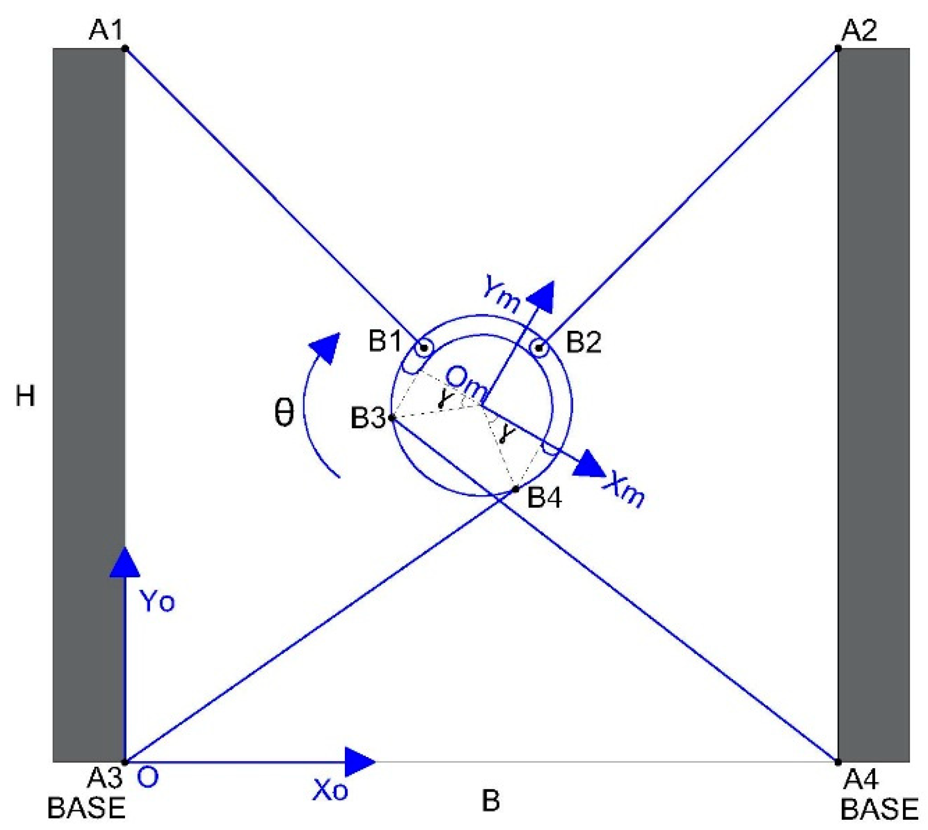
    It must be noted that to avoid collisions between lower cables (B3-A4 and B4-A3) the anchor points are placed in opposite faces of the EE.
  • Case 3: The workspace conditions are those of case 2, but the cable-connection points supporting the robot can move through a restricted segment of the circular periphery mechanism. This segment is delimited by a specified angle.

3. Methodology and Experimentation

The robot’s workspace is determined by the method of analysis-by-intervals.
The feasibility that one or more system solutions will allow the positioning and orienting of the robot in each interval is determined by linear programming. The function to be minimized is tied to a group of restrictions, which are analyzed in the next section. These considerations were implemented using MATLAB, whose computational process is shown in Figure 3.

3.1. Case 1

Figure 4 shows the mechanical structure, cable disposition, and links to the fixed points and the moving platform in case 1. The nomenclature in this case is listed below:
  • H is the height of the anchor points for the cables 2.2 m, and B defines the distance between the poles 3 m.
  • Tmax = 200 N, is the maximum tension on the cables.
Hence, (Xo, Yo) and (Xm, Ym) represent the coordinates of the fixed and mobile platforms, respectively.
The mobile platform of the robot can travel a distance Px on the x axis and a distance Py on the y axis and can rotate through angle θ around the axis perpendicular to the xy plane, as shown in Figure 5.
In the absence of rotation, the workspace of the robot can be the surface delimited by points A1, A2, A3, and A4 of Figure 5. The maximum allowable rotation angles of the platform are investigated here.
T e n s i o n = 0 ,
M o m e n t u m = 0 ,
In the analysis, the forces on the cables are considered as tension forces because cables cannot exert push forces. Therefore, the tension and momentum equilibria in the cables are calculated using Equations (1) and (2), respectively. The vector representations are shown in Figure 6.
If the robot is positioned such that all cables can have tension components along both axes (see Figure 7), the analysis imposes a maximum tension Tmax on the cable. In this case, one can determine the positional workspace limits of the robot on the plane.
Applying Equations (1) and (2), and considering the forces on the x and y axes and the momentum along the rotation axis perpendicular to the plane, the tension balance equations are given by the following:
For forces on the x axis:
T B 1 _ A 1   x T B 4 _ A 3   x + T B 2 _ A 2   x + T B 3 _ A 4   x = 0 .
For forces on the y axis:
T B 1 _ A 1   y + T B 2 _ A 2   y T B 3 _ A 4   y T B 4 _ A 3   y W m s = 0 .
Here, Wms represents the weight of the mobile structure, assumed to be concentrated on its centroid.
Momentum analysis:
Figure 8 adds the Ri vectors extending from the centroid to the points of each applicate tension, where i goes from 1 to 4.
The analysis is given by Equation (5), which executes the cross product between corresponding R and T vectors.
R 1 × T B 1   A 1 + R 2 × T B 2   A 2   + R 3 × T B 3   A 4 + R 4 × T B 4   A 3 = 0
Finally, inequality (6) is introduced, which restricts the tension between zero and its maximum, considering that a cable cannot provide negative tension and that surpassing the maximum tension could lead to a cable break.
0 < T < T m a x
The robot’s workspace is determined by the method shown in Figure 3, where restriction given by Equations (3)–(5), and by inequality (6) are taken into account.
In this scenario, Figure 9 shows the volume that represents the orientation workspace of the robot over the entire positioning space. The axis on this figure are denoted as follow:
  • “Width B” represents the base of the robot on Figure 5, and its scale corresponds to the number of intervals (15) in which it was segmented.
  • “Height H” represents the height of the robot on Figure 5, and its scale corresponds to the number of intervals (15) in which it was segmented.
  • “Max. Angle (degrees)” represents the maximum angle that the robot can rotate for each interval of analysis. In Figure 9a a top view with the positive rotation angles is shown, while Figure 9b shows the bottom view with the negative rotation angles.

3.2. Case 2

The variant respect to Case 1 replaces the EE of rectangular geometry with the EE of circular geometry shown in Figure 2.
Figure 10 shows the cable layout and the links to the fixed and moving points of the platform. The associated forces are shown in Figure 11. For a more general analysis, the center-of-mass of the EE is assumed to be displaced by dcm from the centroid.
As described in case 1, the fixed and mobile coordinate systems are denoted as (Xo, Yo) and (Xm, Ym), respectively. The horizontal and vertical movements of the mobile platform are specified as Px and Py, respectively. The effector is oriented through angle θ around the axis perpendicular to the xy plane, as shown in Figure 12.
The platform can be moved to and oriented at different points, as shown in Figure 13, Figure 14 and Figure 15.
In this case, the system of equations describing the motion and rotational equilibrium must consider the forces acting on the upper cables. These forces act along the line from the centroid to the fixed points where the cables are attached. Recall also that the center-of-mass of the EE is displaced (see Figure 10).
The equilibrium of the forces along the x and y axes is represented by Equations (3) and (4), respectively. When calculating the tension components T B 1   and T B 2   , the unity vector is assumed to extend from the centroids u O m   A 1 and u O m   A 2 to points A1 and A2, respectively, provided that neither B1 nor B2 reaches the maximum value β. If point B1 or B2 reaches β, they will be treated as fixed points. The unity vectors extending from points B1 or B2 are described as u B 1   A 1 and u B 2   A 2 , respectively.
It must be noted that tensions T B 1 and T B 2 generate no momentum when their line of action passes through the centroid. However, the force exerted by the weight W generates a rotational momentum that depends on the orientation angle of the EE. Therefore, we have
R 3 × T B 3   A 4 + R 4 × T B 4   A 3 W · d c m · S i n ( θ ) = 0 .
The workspace of the robot (see Figure 16) is calculated using Equations (3), (4), and (7) through the analysis-by-intervals method. The tensions are restricted to Tmax at most, and the mobile anchor points are considered to slide along the entire periphery of the circular effector. It is important to note that the volume regenerated is larger in comparison to the previous case shown in Figure 9.

3.3. Case 3

Case 3 is a variant of the previous case. The sliding of the upper anchor points is not free but is restricted to the maximum value β (120°), as shown in Figure 8. The workspace is shown in Figure 17. It must be noted that, even though, in this case, the sliding angle was restricted, the volume regenerated is still larger in comparison to case 1 shown in Figure 9 that corresponds to the structure of a robot with fixed anchor points.

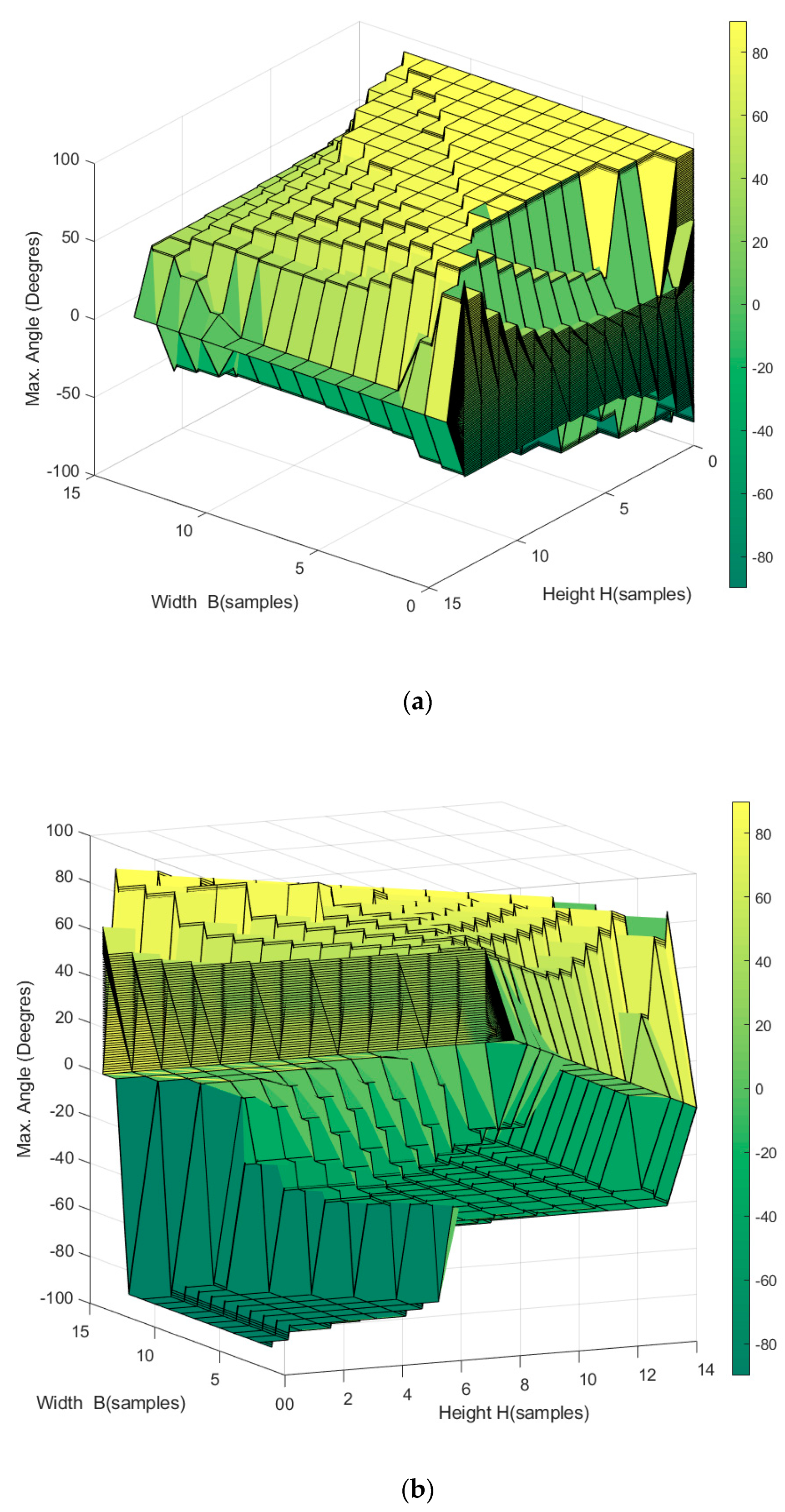
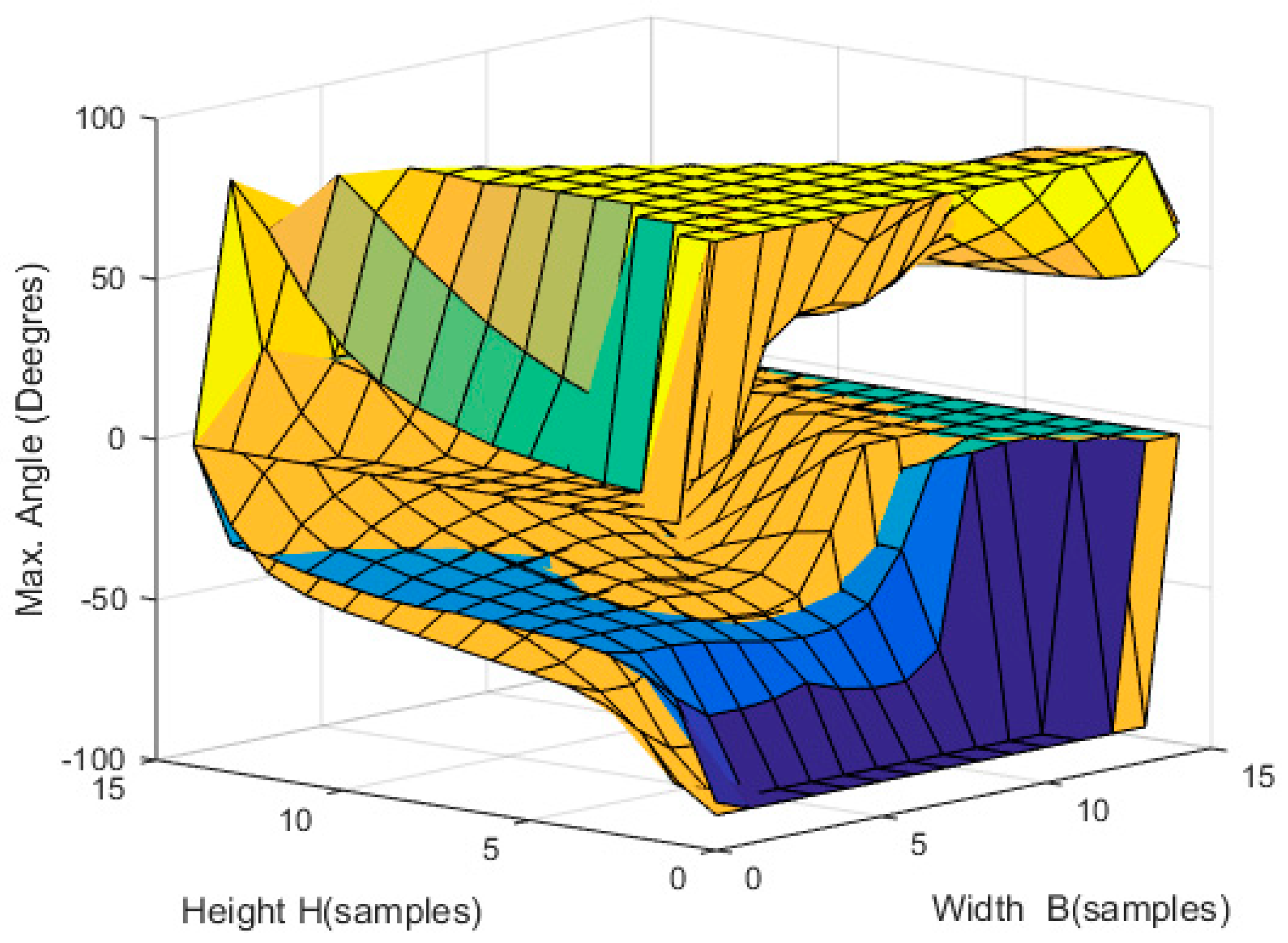
4. Analysis of Results

In case 1, as the position of the robot in the workspace rises along the vertical axis, the reachable positive and negative rotation angles decrease, this is reflected on Figure 9.
Case 2 proposes a new configuration of the mobile structure, in which the upper anchor points of the EE can slide over the defined periphery of the novel mechanism. This configuration notably increases the workspace, especially the orientation workspace. The expanded workspace turns out to be the difference between the workspaces in Figure 9 and Figure 16, as shown in Figure 18.
Finally, in case 3, the sliding zone of the upper anchor points of the EE is restricted to angle β, which limits the workspace from that of case 2. Despite the limited sliding angle of the upper anchoring, the circular structure enables a more extensive workspace than the rectangular case 1. The expanded workspace turns out to be the difference between the workspaces in Figure 9 and Figure 17, as shown in Figure 19.
To exemplify this expansion, the sliding angle was halved to β = 60°. The resulting workspace is shown in Figure 20. Comparing Figure 20 with Figure 9, the expansion of the former becomes evident (see Figure 21).
The results reflect that, if any of the upper sliding points reaches its limit, the robot acquires a new structure, equivalent to a robot with one or two fixed upper anchor points. Under these conditions, it also obtains additional rotation.

5. Discussion

The above results were validated by simulating the robot’s mechanism in ADAMS software.

5.1. Planar CDPR with 3-DoF and a Rectangular EE

In the simulation, the tension in the cables was gradually increased, and the maximum angle through which the EE could turn without exceeding the established maximum force in the cables (in this case, 200 N) was determined. Because the aim was to check the orientation of the robot, the robot’s position was fixed in the center of the workspace.
This simulation results are shown in Figure 22, and the corresponding measurements are plotted in Figure 23.
The angle of rotation reached by the robot without exceeding the maximum tension in the cables 200 N was 33.49° (Figure 23). These results agree with the analysis of Figure 9, which was implemented in MATLAB R2015a and is reproduced in Figure 23b for a better comparison. That is, when the robot was fixed at the central position, the maximum orientation was limited to around 35°. The slight difference is attributed to other physical effects, such as the weight of the cables that ADAMS considers.

5.2. The Planar Reconfigurable Passive CDPR with 3-DoF and an Effector with Circular Geometry

Again, this simulation increased the tension on the cables and determined the angle through which the EE could rotate without exceeding the maximum tension in the cables of 200 N. The robot was centralized in its workspace, and the sliding surface of the mobile points was restricted to 120°.
The simulation results are shown in Figure 24, and the corresponding measurements are plotted in Figure 25.
The rotation angle reached by the robot without exceeding the maximum tension in the cables of 200 N was 89.9° (Figure 25). These results agree with the MATLAB analysis in Figure 16, which is reproduced in Figure 25b for a better comparison. At the central position of the robot, the maximum orientation in the MATLAB analysis was around 80°, close to the value of 89.9° obtained in the ADAMS simulation and coincident with the ADAMS simulation.

5.3. Real Experimental Test of the Passive Reconfigurable Planar CDPR with 3-DoF and the EE with a Circular Geometry

The real experimental test was developed in order to demonstrate the maximum rotation angles. Due to the low characteristics of the prototype materials, the proportional forces that are used are smaller than what was treated in the investigation. In the experiment it was considered a weight, W (suspended mass of 1 kg) that was applied to the center of the mass (Cm). B3 is the anchor point, the indirect force F (suspended mass of 4 kg) was developed. The robot was centralized in its workspace position again, and the sliding surface of the mobile points had a physical restricted of 120°.
The results in Figure 26 show that the EE can rotate with a maximum angle of approximately 85°. The experiment assumes that the anchor point B1 can freely slide around the periphery of the two cavities, without considering the mechanical reinforcement division that this prototype incorporates.

6. Conclusions

The volume representing the workspaces of positive and negative orientations are not symmetrical. Knowing this behavior helps in delimiting the action of the cable control system that can accommodate the robot, that is, the elongation or withdrawal of the cables, as well as the tension forces, can be restricted as required.
Having identified the workspace, future studies could focus on generating optimal trajectories and decreasing the cable vibration by smoothing the movement and orientation trajectories of the robot.
Using the proposed effector with a circular geometry, a model of sliding anchor points can be implemented, giving the robot characteristics of passive reconfiguration, as demonstrated in the present case study. This proposal allows a significantly greater workspace than a robot with the conventional structure, in which the EE has fixed anchor points and a rectangular geometry. In the conventional configuration, the automatic mobility mechanism of the anchor points is not easily adapted.
It was noted that, when either of the upper sliding points reaches its limit, the robot acquires a new structure, equivalent to a robot with one or two fixed upper anchor points at a certain orientation angle. Under these conditions, the orientation space can be increased, provided that the forces in the cables do not exceed their specified maximum.
After validating the results in ADAMS software and real experimentation, it was concluded that the present work contributes to the study of CDPR, presenting a novel passive configuration for the EE which allowed a greater rotation range.

Author Contributions

Investigation, M.A.C.A. and R.S.; Software, M.A.C.A. and G.P.; Validation, M.A.C.A. and R.S.; Writing—Review & Editing, M.A.C.A., A.R. and J.D.P.

Funding

This research was supported by: The Spanish Government Projects under Grant DPI2014-57220-C2-1-P, Grant PGC2018-095939-B-I00, in part by the “RoboCity2030 DIH-CM Madrid Robotics Digital Innovation Hub, S2018/NMT-4331” and funded by the “Programas Actividades I+D en la Comunidad de Madrid”, in part by Structural Funds of the EU, and the GIIRA research group at Universidad Politécnica Salesiana, Ecuador.

Acknowledgments

The authors want to thank Dr. Julio Viola for the suggestions to the final format of the paper.

Conflicts of Interest

The authors declare no conflict of interest. The funders had no role in the design of the study; in the collection, analyses, or interpretation of data; in the writing of the manuscript, or in the decision to publish the results.

References

  1. Martin, A.; Caro, S.; Cardou, P. Geometric Determination of the Cable-Cylinder Interference Regions in the Workspace of a Cable-Driven Parallel Robot. In Mechanisms and Machine Science, Proceedings of the Third International Conference on Cable-Driven Parallel Robots, Quebec City, QC, Canada, 2–4 August 2017; Springer: Berlin/Heidelberg, Germany, 2016; p. 53. [Google Scholar]
  2. Merlet, J.P.; Daney, D. A portable modular parallel wire crane for rescue operations. In Proceedings of the IEEE International Conference on Robotics and Automation, Anchorage, AK, USA, 3–7 May 2010. [Google Scholar]
  3. Alamdari, A.; Krovi, V. Design and Analysis of a Cable-Driven Articulated Rehabilitation System for Gait Training. J. Mech. Robot. 2016, 8, 051018. [Google Scholar] [CrossRef] [Green Version]
  4. Abbasnejad, G.; Yoon, J.; Lee, H. Optimum kinematic design of a planar cable-driven parallel robot with wrench-closure gait trajectory. Mech. Mach. Theory 2016, 99, 1–18. [Google Scholar] [CrossRef]
  5. Lamine, H.; Laribi, M.A.; Bennour, S.; Romdhane, L.; Zeghloul, S. Design Study of a Cable-based Gait Training Machine. J. Bionic Eng. 2017, 14, 232–244. [Google Scholar] [CrossRef]
  6. Gao, B.; Song, H.; Zhao, J.; Guo, S.; Sun, L.; Tang, Y. Inverse kinematics and workspace analysis of a cable-driven parallel robot with a spring spine. Mech. Mach. Theory 2014, 76, 56–69. [Google Scholar] [CrossRef]
  7. Seriani, S.; Gallina, P.; Wedler, A. A modular cable robot for inspection and light manipulation on celestial bodies. Acta Astronaut. 2016, 123, 145–153. [Google Scholar] [CrossRef]
  8. Seriani, S.; Gallina, P.; Wedler, A. Dynamics of a tethered rover on rough terrain. In Advances in Italian Mechanism Science; Springer: Berlin/Heidelberg, Germany, 2017; pp. 355–361. [Google Scholar]
  9. Borgstrom, P.H.; Jordan, B.L.; Sukhatme, G.S.; Batalin, M.A.; Kaiser, W.J. Rapid Computation of Optimally Safe Tension Distributions for Parallel Cable-Driven Robots. IEEE Trans. Robot. 2009, 25, 1271–1281. [Google Scholar] [CrossRef] [Green Version]
  10. Gouttefarde, M.; Merlet, J.P.; Daney, D. Wrench-Feasible Workspace of Parallel Cable-Driven Mechanisms. In Proceedings of the IEEE International Conference on Robotics and Automation, Roma, Italy, 10–14 April 2007; pp. 1492–1497. [Google Scholar]
  11. Bosscher, P.; Riechel, A.T.; Uphoff, I.E. Wrench-feasible workspace generation for cable-driven robots. IEEE Trans. Robot. 2006, 22, 890–902. [Google Scholar] [CrossRef]
  12. Bayaniy, H.; Masoulehy, M.T.; Karimiy, A.; Cardouz, P.; Ebrahimiy, M. On the determination of the maximal inscribed ellipsoid in the Wrench-Feasible Workspace of the cable-driven parallel robots. In Proceedings of the 2nd RSI/ISM International Conference on Robotics and Mechatronics, Tehran, Iran, 15–17 October 2014; pp. 422–427. [Google Scholar]
  13. Merlet, J.P. On the workspace of suspended cable-driven parallel robots. In Proceedings of the IEEE International Conference on Robotics and Automation (ICRA), Stockholm, Sweden, 16–21 May 2016; pp. 841–846. [Google Scholar]
  14. Piao, J.; Jin, X.; Jung, J.; Choil, E.; Park, J.O.; Kim, C.S. Development of a high payload cable-driven parallel robot. In Proceedings of the 17th International Conference on Control, Automation and Systems (ICCAS), Jeju, Korea, 18–21 October 2017; pp. 423–425. [Google Scholar]
  15. Choi, S.H.; Park, K.S. The integrated elasto-plastic cable modeling for cable driven parallel robots (CDPRs). In Proceedings of the 17th International Conference on Control, Automation and Systems (ICCAS), Jeju, Korea, 18–21 October 2017; pp. 420–422. [Google Scholar]
  16. Wang, B.; Zi, B.; Qian, S. Collision free force closure workspace determination of reconfigurable planar cable driven parallel robot. In Proceedings of the Asia-Pacific Conference on Intelligent Robot Systems, Tokyo, Japan, 20–22 July 2016; pp. 26–30. [Google Scholar]
  17. Anson, M.; Alamdari, A.; Krovi, V. Orientation Workspace and Stiffness Optimization of Cable-Driven Parallel Manipulators with Base Mobility. J. Mech. Robot. 2017, 9, 031011. [Google Scholar] [CrossRef]
  18. Rodriguez-Barroso, A.; Saltaren, R.; Portilla, G.A.; Cely, J.S.; Carpio, M. Cable-Driven Parallel Robot with Reconfigurable EE Controlled with a Compliant Actuator. Sensor 2018, 18, 2765. [Google Scholar] [CrossRef] [PubMed]
  19. Duan, Q.; Vashista, V.; Agrawal, S.K. Effect on wrench-feasible workspace of cable-driven parallel robots by adding springs. Mech. Mach. Theory 2015, 86, 201–210. [Google Scholar] [CrossRef]
  20. Gagliardini, L.; Caro, S.; Gouttefarde, M.; Girin, A. Discrete reconfiguration planning for Cable-Driven Parallel Robots. Mech. Mach. Theory 2016, 100, 313–337. [Google Scholar] [CrossRef] [Green Version]
  21. Barbazza, L.; Oscari, F.; Minto, S.; Rosati, G. Trajectory planning of a suspended cable driven parallel robot with reconfigurable end effector. Robot. Comput. Integr. Manuf. 2017, 48, 1–11. [Google Scholar] [CrossRef]
  22. Nguyen, D.; Gouttefarde, M. Study of reconfigurable suspended cable driven robots for airplane maintenance. In Proceedings of the IEEE International Conference on Intelligent robots and systems, Chicago, IL, USA, 14–18 September 2014; pp. 1682–1689. [Google Scholar]
  23. Pott, A. Determination of the Cable Span and Cable Deflextion of Cable-Driven Parallel Robots. In Cable-Driven Parallel Robots; Springer: Berlin/Heidelberg, Germany, 2018; pp. 106–116. [Google Scholar]
  24. Zhao, T.; Zi, B.; Qian, S.; Yin, Z.; Zhang, D. Typical configuration analysis of a modular reconfigurable cable-driven parallel robot. Int. J. Adv. Robot. Syst. 2019, 16. [Google Scholar] [CrossRef] [Green Version]
  25. Qian, S.; Zi, B.; Wang, D.; Li, Y. Development of Modular Cable-Driven Parallel Robotic Systems. IEEE Access 2019, 7, 5541–5553. [Google Scholar] [CrossRef]
  26. Kang, X.; Dai, J. Relevance and Transferability for Parallel Mechanisms with Reconfigurable Platforms. J. Mech. Robot. 2019, 11. [Google Scholar] [CrossRef]
Figure 1. EE with the classical rectangular geometry.
Robotics 08 00057 g001
Figure 2. EE with a circular geometry with top passive reconfigurable anchor points for a four-cable parallel robot.
Robotics 08 00057 g002
Figure 3. Flowchart for maximum rotate calculation by interval analysis.
Robotics 08 00057 g003
Figure 4. 3-DoF CDPR with an EE configured in the classical rectangular geometry.
Robotics 08 00057 g004
Figure 5. Degrees of freedom (linear motions along two axes and orientation motion around one axis) of the 3-DoF CDPR.
Robotics 08 00057 g005
Figure 6. Distributions of forces in the rectangular EE: (a) Without rotation and (b) with rotation.
Robotics 08 00057 g006
Figure 7. Position of workspace analysis for the planar CDPR with 3-DoF in a common case.
Robotics 08 00057 g007
Figure 8. Tensions and radial distances to the anchoring points in the planar parallel robot with 3-DoF.
Robotics 08 00057 g008
Figure 9. Orientation workspace of the planar CDPR with 3-DoF and a rectangular-geometry EE, (a) top view showing positive rotation angles, and (b) bottom view showing negative rotation angles.
Robotics 08 00057 g009aRobotics 08 00057 g009b
Figure 10. Cable layout of the passive reconfigurable planar CDPR with 3-DoF and an EE with circular geometry.
Robotics 08 00057 g010
Figure 11. Involved forces in the EE of the four-cable passive reconfigurable planar robot with a displaced center-of-mass: (a) No rotation; (b) during rotation respect to its centroid.
Robotics 08 00057 g011
Figure 12. Position and orientation components of the four-cable passive reconfigurable planar CDPR with circular geometry.
Robotics 08 00057 g012
Figure 13. Arbitrary position of the non-rotated for the passive reconfigurable planar CDPR with 3-DoF.
Robotics 08 00057 g013
Figure 14. Arbitrary position of a positively rotated for the passive reconfigurable planar CDPR with 3-DoF.
Robotics 08 00057 g014
Figure 15. Arbitrary position of a negatively rotated for the passive reconfigurable planar CDPR with 3-DoF and an EE with circular geometry.
Robotics 08 00057 g015
Figure 16. Workspace of the passive reconfigurable planar CDPR with 3-DoF, (a) top view showing positive rotation angles, and (b) bottom view showing negative rotation angles. In this case, the slide angle of the upper anchor points is not restricted to the periphery of the effector.
Robotics 08 00057 g016
Figure 17. Workspace of the passive reconfigurable planar CDPR with 3-DoF, (a) top view showing positive rotation angles, and (b) bottom view showing negative rotation angles. In this case, the upper anchor points are restricted to a symmetric guide through the angle β (120°) on the periphery of the effector.
Robotics 08 00057 g017
Figure 18. Expanded workspace in a passive reconfigurable planar CDPR with 3-DoF with respect to the workspace of the robot with fixed anchor points.
Robotics 08 00057 g018
Figure 19. Expanded workspace in a passive reconfigurable planar CDPR with 3-DoF and limited angle β = 120° with respect to the workspace of the robot with fixed anchor points.
Robotics 08 00057 g019
Figure 20. Workspace of a passive reconfigurable planar CDPR with 3-DoF, (a) top view showing positive rotation angles, and (b) bottom view showing negative rotation angles. In this case, the upper anchor points are restricted to a symmetric guide through the angle β = 60°.
Robotics 08 00057 g020
Figure 21. Expanded workspace in a planar reconfigurable passive CDPR with 3-DoF and limited angle β = 60° with respect to the workspace of the robot with fixed anchor points.
Robotics 08 00057 g021
Figure 22. Simulation of the planar CDPR with 3-DoF and rectangular EE geometry.
Robotics 08 00057 g022
Figure 23. (a) Measured tensions and angles of the planar CDPR with 3-DoF and a rectangular EE, (b) Reproduction of Figure 9a obtained with MATLAB.
Robotics 08 00057 g023
Figure 24. Simulation of the passive reconfigurable planar CDPR with 3-DoF and an EE with circular geometry.
Robotics 08 00057 g024
Figure 25. (a) Measured tensions and angles of the passive reconfigurable planar CDPR with 3-DoF and an effector with circular geometry, (b) reproduction of Figure 16a obtained with MATLAB.
Robotics 08 00057 g025aRobotics 08 00057 g025b
Figure 26. Rotation angle experiment of the passive reconfigurable planar CDPR with 3-DoF and the EE with a circular geometry; it is possible to see the force of point B3 in the right side of the photo.
Robotics 08 00057 g026

