Abstract
Several bio-inspired underwater robots have been demonstrated in the last few years that can horizontally swim using different smart actuators. However, very few works have been presented on robots which can swim vertically, have a payload and resemble a jellyfish-like creature. In this work, we present the design, fabrication, and performance characterization of a new tethered robotic jellyfish, which is based on inflatable soft pneumatic composite (SPC) actuators. These soft actuators use compressed air to expand and contract, which help the robot to swim vertically in water. The soft actuators consist of elastomeric air chambers and very thin steel springs, which contribute to gaining faster motion of the biomimetic robot. A prototype of 220 mm in diameter and consisting of eight actuating units was fabricated and tested underwater in a fish tank. It reached a height of 400 mm within 2.5 s while carrying a dead weight of 100 g when tested at 70 psi (483 kPa) pressure. This high performance (160 mm/s on average speed) suggests that faster motion with a payload can be achieved by using SPC actuators. The inflatable structures help to flap the bell segments as well as in buoyancy effect for rapid vertical motion. The major achievement of this work is the ability to demonstrate a novel use of inflatable structures and biomimetic flapping wings for fast motion in water. The experimental and deduced data from this work can be used for the design of future small unmanned underwater vehicles (UUVs). This work adds a new robot to the design space of biomimetic jellyfish-like soft robots. Such kind of vehicle design might also be useful for transporting objects underwater effectively.
1. Introduction
Biomimetics implies the study of anatomy and mechanisms present in nature and creating a model or system using synthetic materials for solving complex engineering problems. This approach is crucial for advancements in science and technology [1]. Soft robotics is one such field, which focuses on replicating the movement of biological creatures using soft synthetic materials. Compared to soft robots, conventional robots have rigid structures that limit their motions. Soft robotics brings in a new dimension of motion due to soft robots’ fluidic movement and many degrees of freedom [2,3,4]. Pneumatic networks (Pneu-Nets) are fluidic actuators, which bend with the help of compressed air [5,6,7], their motion direction can be controlled by changing the design and placement of the inextensible layer. The wall thickness and the size of the chamber affect the motion and the time required to inflate it completely [8,9]. Based on this, many biomimicry related studies and inventions have been made, such as a soft robotic tongue [10], soft robotic manipulators [11], a quadruped [12], an octobot (a soft robot with microfluidic controller) [13], a snake-like robot and a self-contained robotic fish [14]. Soft robotics is not only limited to biomimicry, but also has been extended to wearable devices to help the rehabilitation of physically impaired individuals. Thumb assistance and ankle foot rehabilitation are a few examples of soft wearable devices [15].
Most of the biomimetic underwater robots presented in the literature are based on the common fishes (Tuna, carp, and catfish). However, jellyfish species have been considered by researchers in recent years. Based on the swimming mechanism, jellyfish can be categorized into two types, called Prolate and Oblate. Prolate species use jetting type and Oblate species use rowing type of propulsion [16]. Jellyfish of different species have been chosen for biomimicry due to their energy efficiency during swimming, the ability to incorporate payload and the ability to select various sizes for a model vehicle since there are species that range from millimeter to meter scale. Biologist explained that the motion of a jellyfish is due to the contraction of the bell and expulsion of fluid through the bell to generate a thrust [16]. The movement of the bell and the flow pattern produces unsteady vortices, which are also highly responsible for its motion. Previously developed jellyfish-like robots have used shape memory alloy (SMA), ionic polymer metal composite (IPMC) and electrical motors to mimic the bending motion. An example of jellyfish developed using electric motor and linkage mechanisms is AquaJellies 2.0 developed by Festo Corp., which has elegant gliding motion through water [17]. Xiao et al. showed the implementation of a jellyfish-like motion using servos and four six-bar linkage mechanism [18]. Villanueva et al. in 2009, presented a jellyfish named JetSum made of thin aluminum sheets actuated using biometal fiber (a type of SMA). The jellyfish was able to mimic the motion of a natural jellyfish with jetting type motion, the main challenge for that work was the high-power consumption for the multiple SMAs [19]. A more biomimetic version, named Robojelly was introduced by Villanueva et al. in 2011 [20]. Powering aspect has been investigated by Tadesse et al., in 2012 using composite actuators consisting of multiwall carbon nanotubes, shape memory alloy, and platinum particles that enable the utilization of fuel power such as hydrogen and oxygen gas [21]. Another large-size jellyfish inspired by cyanea capillata species was developed using linear actuators in 2013 by Villanueva et al. [22]. In the extremely small size, Guo et al. used IPMCs to develop a microrobot jellyfish. The system was efficient in creating thrust but did not have the ability to carry payload [23]. Naworth et al. showed a novel jellyfish created using chemically disassociated rat tissue and silicone polymer, which responded to electrical field stimulation. They discussed the use of natural material and tissue to create the jellyfish that was never done before [24]. However, the approach uses several chemicals and may be challenging to implement in macroscale robotic systems. Recently, Frame et al., in 2018 showed a soft jellyfish robot that uses hydraulic systems (water based) for actuation using DC motor pumps. It was demonstrated the robot performed successful field test in the ocean [25]. In our robot, we used a pneumatic system using compressed air and the geometry of the tentacles are also different, they used oblong shape to compensate unequal flow of water in their tentacle design. However, we used a single compartment design for our prototype presented in this study.
The principal movement mechanism in jellyfish-like robots is thrust generation by jetting motion of the fluid beneath the robot. The objective of this paper is to investigate the performance of a jellyfish-like robot such as vertical movement in a fish tank, cyclic motion and deformation with and without payload at different heights in a water column. Payload and swimming ability are important characteristics of such robots when it comes to moving an object from point A to B in water. In this work, we used soft pneumatic composite (SPC) actuators to produce the contraction and expansion of the bell. These are completely different from the SMAs [19], SMA composite (BISMAC) [26], servos [22] and conducting polymers [27] which our group and collaborators used before. We called the prototype FludoJelly and it is powered by an air compressor, which inflates the actuators and bends them to create a smooth motion. The actuation required a quick pulse input followed by recovery phase. The thrust was generated in the quick actuation phase followed by a gradual relaxation phase. Position and velocity were measured under different input conditions. Sung-Weon et al. discussed a similar bio-inspired pulse for the actuation of their IPMC actuated jellyfish [28]. The other interesting aspect of this FludoJelly is the “inflatability” of the structure. Inflatable structures are found in various creatures for various purposes. Figure 1A–C shows various jellyfish species, moon jellyfish (Aurelia aurita) that ranges from 100 to 400 mm, and true jellyfish, Mastigiidae (Phyllorhiza) that ranges from 300 to 600 mm. Figure 1A is a colony of jellyfish-like creatures also known as Portuguese man-of-war (Physalia) and the sizes range from 100 to 150 mm. This animal resembles a jellyfish, but it is not a single multicellular organism (like the common jellyfish). It is a colony of small specialized animals. It has an inflated structure at the top that enables it to float keeping the rest of the body to be under the water. The species shown in Figure 1B,C do not have inflatable structures, rather they use an undulatory motion of their bell for movement. Figure 1D–F show other animals with inflatable structures in their body. A frog is a typical example that inflates its vocal sac to attract mates. Another example is a frigate bird which has a wingspan of 2.3 m, and also other marine mammals such as a walrus which uses inflation for buoyancy and to sleep better [29].
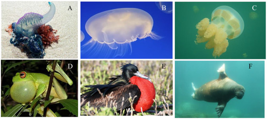
Figure 1.
Jellyfish species and animals that have inflatable structures. (A) Portuguese man-of-war, physalia, courtesy of Pixabay GmbH/Alicia Campbell; (B) Moon Jellyfish, Aurelia aurita, photo courtesy of Armita Hamidi; (C) True Jellyfish, Mastigia, photo courtesy of Quin Marshall [30]; (D) Frog, Litoria chloris [31]; (E) Frigatebirds, courtesy of Galapagos Conservation Trust, photographer Martin Partridge; (F) Walrus, Odobenus rosmarus, photo courtesy of Pixabay GmbH/Sven Schlieter.
Considering the benefits of using soft composite and inflatable structures, we have designed and developed the novel fluidic actuated robot, FludoJelly. This robot has a faster speed than the existing prototypes while carrying a payload, which has not been demonstrated in any literature so far. The core contribution of this work is the data obtained from the prototype using the experimental method, the fabrication techniques, and the design. This data helps in creating such a fast-moving jellyfish-like robot. The displacement of the robot while carrying a payload, the influence of pressure on the deformation of the bell segment at different heights in a water column, and cyclic motion of the robot while tethered are some of the key contributions.
The paper is organized as follows. First, we will describe the design of a single actuator and the fabrication of the jellyfish prototype; we then describe the experimental setup and data collection. Results and discussion will be the next, followed by the swimming test and comparison of the swimming performance of our robot with existing prototypes. Conclusion and future works are presented at the end.
2. Materials and Method
2.1. Soft Pneumatic Composite (SPC) Actuator
The pneumatic actuator is based on the actuator design originally developed by Harvard University [32]. However, our actuator consists of one single chamber and thin spring steel in the outer layer, which inflates to create a bending motion. To create the bending motion an inextensible material is embedded into the soft material. Paper and PDMS (polydimethylsiloxane) are commonly used as an inextensible layer in soft robots. The main idea behind designing the actuator was to have a maximum thickness on the side and minimum thickness on the top to obtain the maximum utilization of the amount of air entering the chamber. The pressure inside the chamber will follow the path of least resistance, thereby inflating more from the top layer of the actuator compared to the sides. Figure 2A shows the cross section and the side view of the actuator, which was made of two-piece mold and casting silicone.
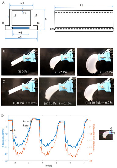
Figure 2.
Single soft pneumatic composite (SPC) actuator. (A) Schematic diagram of the actuator from two views; (B) Actuation at different pressure (i) 0 psi before actuation, (ii) at 2 psi, (iii) at 7 psi; (C) Pulsed actuation (i) at 0 psi 0 ms pulse duration, (ii) at 10 psi 100 ms pulse duration and (iii) at 10 psi at 250 ms. The actuator geometry is 76 mm × 19 mm × 15 mm in length (L1), width (w1) × thickness (h). The other dimensions are t1 = 2 mm, t2 = 3 mm, t4 = 5mm, t5 = 127 µm, w2 = 12.7 mm, and w3 = 21 mm; (D) Vertical movement of SPC actuator vs time.
The silicone used for our actuator is Ecoflex-30, which has a shore hardness of 00–30, up to 900% elongation at break, and a tensile strength of 200 psi (1.4 MPa) [33]. The new structure is the use of spring steel (blue rectangle in Figure 2A) as the inextensible layer at the bottom. The advantage of using spring steel is its spring-back effect. When a force is applied to a spring steel on one end and released suddenly, it retracts to its original position quickly. This structure was effective for SMA based systems as well [20]. In our case, the force is applied when compressed air is filled in the chambers. The material of the spring is 1095 blue tempered steel with a thickness of 0.005” (t5 = 127 µm) and a width of 0.5’ (w2 = 12.7 mm). The leaf spring is embedded in a skin silicone. It takes 3–4 hours for the silicone to fully cure under room temperature. A tube for inflation is inserted into the actuator through a nipple extrusion and zip tie is wrapped around the nipple to hold the inserted tube in place. Figure 2B shows the undeformed SPC actuator at the first column followed by the deformed shapes of the actuator at pressure 2 and 7 psi (14 and 48 kPa). Figure 2C shows the inflated structure at different actuation times 0, 0.1 and 0.25 s (video S1, supplementary file, Video S1 FludoJelly1, SPC actuators.mp4). The vertical displacement is 22 mm as shown in the time domain plot in Figure 2D, the left axis. When normalized with the length, the maximum vertical displacement is 28% as shown in the right axis. The negative indicates the direction of bending.
The bending angle () of the actuator is a function of three parameters: geometry, input pressure and material constants such as elasticity. This relation can be described by the equation obtained from Onal et al. [34].
represents the length of the channel of the actuator and denotes the height of the actuator channel, is the strain of the actuator which is a nonlinear function of stress, is the number of channels for multi-chambered actuator, in our case n = 1. Additionally,
where is the stress developed due to internal pressure supplied to the actuator and is the change in height due to pressure of the actuator. From the above two equations (Equations (1) and (2)), the bending angle of such actuator is dependent on pressure, geometry of the actuator, elastic constants in a nonlinear manner [35,36]. The exact equation that predict the deformation is more complicated as the actuator consists of multiple materials. However, the simplified equations will provide an insight on the behavior of the actuator and guide the research. Our focus in this paper is mainly on experimental investigation of the jellyfish-like robot. We do not provide rigorous equations and validation with experimental data due to the complex nature of the problem.
2.2. Biomimetic Jellyfish Design
The design of the robotic structure is inspired from movement of the natural jellyfish similar in overall structure as our previous prototypes. It has eight SPC actuators arranged radially like a disc. The circular array of actuators is cast from a two-piece mold as shown in Figure 3A,B. The leaf-springs are arranged in the same orientation as the actuators (Figure 3C). This approach improves the swimming speed. The cast created earlier is then bonded with the silicone skin embedded with spring steel seen in Figure 3D. The thickness of the skin is 3 mm. The main aim of the prototype is to mimic the bell contraction and expansion movement to gain lift. Air is supplied through a single tube through the center portion from an air compressor. The actuators bend downwards creating a contracted bell like structure. Figure 3E,F shows the actuation before and after respectively. One of the challenges faced in fabricating the structure was bonding the layers and sealing it. Depending on the thickness of the air chamber, the trapped air during casting can give rise to small air bubbles in the structure. These air bubbles can create pores causing leaks inside the air chamber. Such problems can be avoided by casting silicone inside a vacuum chamber.
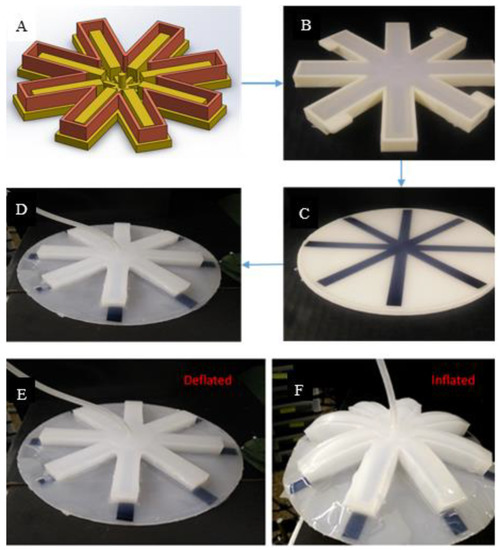
Figure 3.
Jellyfish inspired robot based on fluidic actuation and spring steels—FludoJelly. (A) Computer-aided design (CAD) model of the 2-piece mold for casting the soft robotic jellyfish structure; (B) elastomeric chambers created by the mold; (C) 1095 leaf spring embedded in silicone; (D) Elastomeric chamber and leaf spring embedded together to form the bell; (E) Jellyfish in its deflated phase or relaxation phase; (F) its inflated stage or contraction phase.
2.3. Experimental Setup for Testing Swimming
The swimming motion of the robotic jellyfish was tested using different cameras while the robot was tethered underwater as shown in the schematic diagram in Figure 4A. These cameras were used for characterizing and verifying the motions with different measurement conditions and at different frame rates. A pressure control circuit was made to control the actuators as shown in the schematic diagram in Figure 4B and the photograph of the setup is shown in Figure 4D. The air compressor used here is single stage air compressor (California Air tools Model no. 202977393) which can generate a maximum pressure of 120 psi. Solenoid valves (STC 2P025) were used to direct the air flow in the pneumatic circuit, the valves were 2/2 valves and required a 12 V power supply. An external DC power source was used to provide the required voltage. A MOSFET was used to act as a switch and energizing the solenoid. A pressure sensor (Honeywell-ASDX AVX030PG2A5) was also installed in the circuit for pressure readings. The data from the pressure sensor was collected from a National Instruments data acquisition unit NI USB 8452 through LabVIEW program. The pressure sensor used here is an I2C network interface digital output sensor.
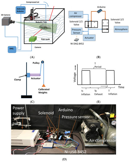
Figure 4.
Experimental setup for testing (A) Position and velocity tracking of the FludoJelly; (B) Circuit for actuation test; (C) Blocking force determination of the SPC actuator; (D) The photograph of the actuation unit; (E) The input voltage given to the solenoid to control the flow.
The blocking force and free strain (the displacement) of a single SPC actuator at different loading conditions was performed as shown in Figure 4C. Dead weights were attached to a pulley and connected to the tip of the actuator. One end of the actuator was clamped, and the other end was attached to calibrated weights using an inelastic wire. The wire was passed over a pulley to provide a smooth movement. The deflection of the tip of the actuator was recorded corresponding to the original position. The weights attached were from 10 g to 50 g in an increment of 10 g. A preliminary test was done at a pressure of 7 psi and we obtained a deflection of 40, 30, 10, 8 and 7 mm corresponding to the loads (10, 20, 30, 40 and 50 g). Most of the experiments were done by providing a pulse actuation, supplying the signal shown in Figure 4E to the solenoid and controlling the pressure.
The swimming motion of the prototype robot was done as follows: The prototype was actuated by supplying air through an inflation and deflation system. The system was controlled using Arduino Uno board. The pulse width of actuation of the solenoid was varied to see the effect in swimming. The experiment was also conducted by sweeping the required supply pressure that will give the maximum bending and the fastest movement. The actuation time or inflation time (Ti) was 500 ms and the exhaust time or deflation time (Te) was 1200 ms.
All the swimming motion tests were performed using a glass fish tank of length 35” (889 mm), width 18” (457 mm) and height 25” (635 mm). The circuit discussed before was used to actuate the jellyfish and determine its properties. The first characterization experiment of the prototype was carried out using a Kinect camera to track the positions. The images were acquired at 12 fps using a camera through MATLAB. A red marker was placed on the FludoJelly to track the position in time. The schematic diagram of the experiment is shown in the figure (Figure 4A). A weight of 50 gm was added to the bottom of the prototype to make it neutrally buoyant. Later, a high frame rate camera (Cannon) was used to test the fast motion while varying the supply pressure from 50 psi (345 kPa), 60 psi (414 kPa) and 70 psi (483 kPa). We added another load and tested the robot with 100 g load payload and varying the pressure to see its performance under higher load.
One may think that the inflation of the fluidic compartment alone may yield floating of the prototype. However, that is not the case because the jellyfish is carrying a heavy weight (100 g) compared to its own weight (500 g). It will sink to the bottom of the fish tank and it needs to flap the bell to swim vertically. The air supplied to the compartment helps in bending the bell segments, push the water out, and create a vortex. Additionally, the volume change of the chamber will have an effect in lifting the prototype upward (buoyancy effect). Therefore, the vertical swimming of the robot is a contribution due to volume change as well as due to the bending of the actuator. To see the effect of one of them, we secured the prototype at different height and tested the deflection (bending) due to the pressure input. This will be discussed later.
3. Results and Discussion
3.1. Displacement Profile XY Trajectories of the SPC Actuators
To understand the behavior of the SPC actuator that is used in the robotic jellyfish, we analyzed the displacement profile using a high speed camera (Phantom Miro eX2). Two circular markers were placed, first at the end of the actuator and second at the mid-point of the actuator. The points tracked through the camera were plotted in MATLAB and shown in Figure 5A and the trajectories are shown in Figure 5B. To compare with the commonly used multi-chambered soft actuator PneuNet, a prototype with 6 small chambers each 22 × 24 × 15 mm3 compartment were made and tested as shown in Figure 5C. Two points were tracked like the previous case. The trajectories obtained are shown in Figure 5D. Three points tracking of the actuator is shown in Figure 5E and the corresponding trajectories are shown in Figure 5F. The two points and three points tracking were done to check the trajectories along different points. It was observed that forward and backward trajectories of each of these points are not the same. This is due to the slight hysteresis in the pneumatic system. More studies on this structure should be done in the future to see the effect of geometry and materials. Trajectories of the bell segments are one of the important aspects in the motion of robotic jellyfish [20,26,37], and so we added the trajectories of the current actuators. In this work, we used a single chamber instead of a multi-chamber arrangement because unequal expansion of the chambers and delay in inflation of the successive chambers resulted in an undesired motion.
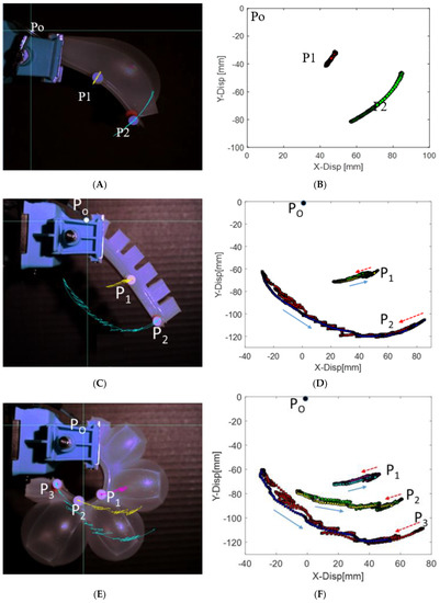
Figure 5.
Actuators and their XY trajectories: (A,B) Actuator 1 with single chamber and spring steel, (C,D) Actuator 2 with multiple chambers and two point tracked, (E,F) Actuator 2 with multiple chambers when three points are tracked along the edge.
3.2. Position Tracking During Swimming of the Fludojelly
The swimming motion of the FludoJelly was analyzed from recorded videos using Phantom Miro, camera at frame rate 50–1200 fps from experimental setup shown earlier. The videos were analyzed and plotted in MATLAB. The result is shown in Figure 6A. FludoJelly was tested at three different pressures 50, 60 and 70 psi. The frequency of actuation was 0.83 Hz, actuation time of 0.25 s and pacification time 1.2 s for all the experiments. This signal shown in Figure 4E was provided to the solenoid keeping Ti = 250 ms for contraction pulse and Te = 1200 ms for relaxation pulse. The result of the swimming test in underwater environment is shown in Figure 6A. From the figure, we can say that the prototype showed high slope in vertical motion (160 mm/s) with respect to time at higher pressure 70 psi. It moved 500 mm from the initial position 100 mm (400 mm displacement) within 2.5 s. We observed the motion of the prototype while carrying a payload mounted at the bottom (Video S2 FludoJelly2 100 g payload.mp4 supplementary). This was consistent with another swimming test when the weight of the payload was 50 g. The result for 50 g load is not presented, but similar increase in slope was obtained as the pressure was increased. The arrows in the figure show the initial position of the robot during the vertical motion. In Figure 6B, the velocity of the robot tracked from an open source tracking software [38] is shown. It was observed that as the pressure was increased from 50 psi to 70 psi, the number of cycles needed to reach the top of the tank decreased. The scattered points are due to tracking error of the video and can be ignored. However, the velocity harmonics for each pressure test can be seen in the figure clearly. Photographs of the robot at different time intervals are also shown in Figure 7. We did not study the vehicle from fluid dynamic point of view such as added mass effect as explained in [39], but such theoretical framework will be essential to study such systems and this is left to future works.
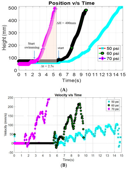
Figure 6.
Tracking the position (A) and velocity (B) of the prototype FludoJelly at different pressure 50, 60 and 70 psi while carrying a dead weight of 100 gram.
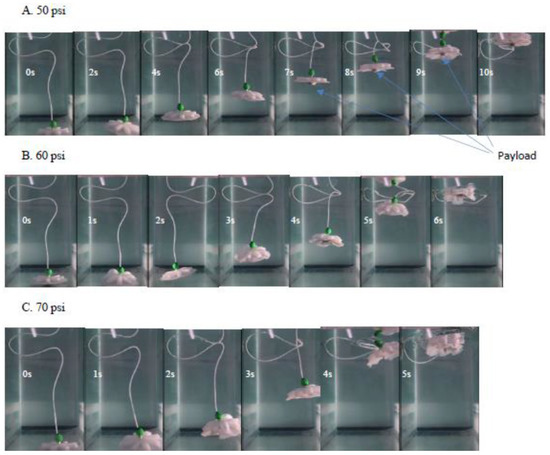
Figure 7.
Photograph of the robot while swimming carrying 100 g load at different supply pressure (50(A), 60(B) and 70 psi(C)) using fast camera for motion capture. All the photos were taken at 1 s intervals after it start moving.
The trajectory of the robot is not a perfect vertical motion (z-direction). The robot moves in the 3D space slightly. As can be seen in Figure 8, it moves in the x and y directions. Some bell segments inflate more than others, and this creates some side movement of the robot. The variation is due do slight differences in the thicknesses of the walls of the air compartments, which indicates that this variable should be carefully designed. The results in Figure 8 are the motion trajectories obtained from high speed camera recorded at 600 fps and plotted with Phantom Camera Control (PCC) software. Our high speed camera, Phantom Miro can capture a video from 50–1200 fps, which can be selected depending on the need.
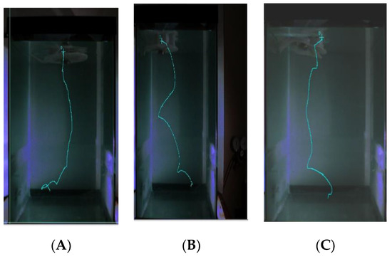
Figure 8.
Trajectory of FludoJelly recorded with speed camera and varying input pressure. (A) 50 Psi; (B) 60 Psi; (C) 70 Psi.
3.3. Cyclic Actuation of the FludoJelly
To check the cyclic motion of the robot, tests were done by supplying constant pressure (50, 60 and 70 psi) with 100 g payload and controlling duration. The pulse period was 20% duty cycle at 0.8 Hz frequency (250 ms on and 1000 ms off). The experiment was done as follows. The pulse pressure was given until the prototype reached to the top of the fish tank. Once it reached the top, the supply pressure was stopped allowing the prototype to sink. When it reached to the bottom of the tank, another cycle of the pulse was provided, and this process was done three times. The results for the three different cyclic pressures obtained from the tracking software are shown in Figure 9. Video of the test is also provided as supplementary information (Video S3 Cyclic Swimming FludoJelly 60 psi 1X.mp4). As can be seen in the figure, the effective height of 400 mm was obtained for all three cycles and the frequency of swimming up and sinking down (one complete cycle) was 0.05 Hz. The rising phase (orange shaded region in Figure 9) is the powered cycle due to the pulse air pressure and the downward (blue region) is the sinking phase due to the attached weight, thereby making the sinking-down cycle longer.
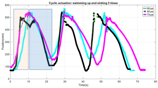
Figure 9.
Cyclic actuation of FludoJelly moving vertically and down in a fish tank when different pressure is supplied at 50, 60 and 70 psi and carrying 100 gm mass payload.
3.4. Testing Deflection of the Bell at Different Height in A Water Column
In this test, the FludoJelly was fixed at a specific height inside the fish tank and the deflection of the bell was measured using the camera. The purpose of this test is to investigate whether the water height influenced the bell deformation and quantify the magnitude. The position of the actuator of the FludoJelly is like a cantilever beam as shown in Figure 10A. The prototype was clamped as shown in Figure 10B and kept inside the fish tank at a different height. The experimental setup consists of a fish tank, the prototype, fixture, solenoid valves and actuation circuit. The actuation circuit consists of Arduino Uno board, pressure sensors and the air compressor as seen in Figure 10C. The actuation sequence was programmed and sent to the Arduino Uno board. The FludoJelly was then actuated at heights of 150 mm, 300 mm and 450 mm, measured from the bottom of the fish tank by varying the gauge pressure at 50, 60 and 70 psi at each height. The deflections of the bell were recorded using a camera operated at 30 fps. Subsequently, an open source image processing software (Physlets Video Tracker) was used to track a specific point marked on the FludoJelly and the results were obtained. Figure 11A represents the deflection vs time characteristics obtained during the actuation of FludoJelly at 150 mm height from the bottom of the fish tank. Here, we can see that the deflection of the bell increases as we increase the input air pressure (gauge pressure). A similar trend can be observed from Figure 11B at height 300 mm and Figure 11C at height 450 mm. The importance of this figure (Figure 11) is that it shows that the forward actuation is so quick due to the air pressure, whereas the return is slower because the air slowly leaves the air chamber (it is not a forced flow). A percentage deflection at each height and each pressure can be seen from Figure 12. The maximum deformation percentage of the bell segment is 59% (the deflection is 45 mm and the length of the bell segment is 76 mm). From this experiment, we can say that as we increase the height of the jellyfish position inside the fish tank, the deflection of the FludoJelly also increases slightly. The minimum percentage deflection of 45% was obtained at the height of 450 mm and 50 psi pressure. Supplementary video is provided for the flapping characteristics at different height (Video S4 Height Deflection of the Bell 1.5X.mp4).
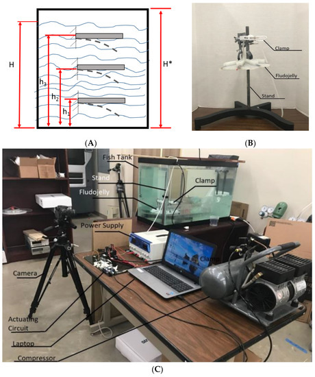
Figure 10.
Experimental setup for testing bell deformation at specific height in a fish tank. (A) Schematic diagram of the cantilever beam at various heights in water; (B) Experimental setup for the test and (C) Jellyfish prototype with stand and clamp.
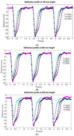
Figure 11.
Deflection profile at different height above the base of the fish tank (A) 150 mm, (B) 300 mm and (C) 450 mm. The length of the bell is 76 mm and the deflection distance can be normalized by the length.
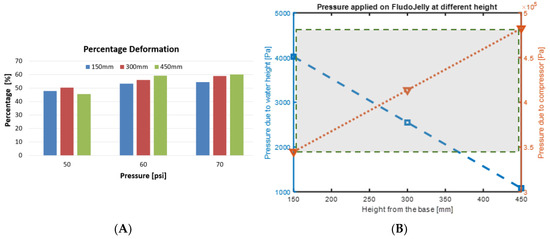
Figure 12.
(A) Percentage deflection vs pressure of the bell (length 76 mm) at different heights in a water column, (B) the pressure due to water height and the pressure applied through the compressor showing the 100× order of magnitude difference.
Additionally, a maximum deflection of 46 mm was obtained at height of 450 mm and 70 psi pressure. Theoretically, the pressure applied on the FludoJelly at different height can be found by the following relation:
where is the pressure, is density of the fluid, is acceleration due to gravity and is height of the fluid.
From Figure 10A, we have H* which represents the total height of the fish tank, 635 mm. H represents the total water level height, ~560 mm. The heights where the FludoJelly was clamped in the fish tank during experiment were , and . Therefore, the pressure at height h1 is which is less as compared to pressure acting at height and . Since the quantity ( increases from to , the pressure increases as we go down in the fish tank. Hence, due to the increase in pressure, less deflection is seen at the bottom position as compared to the top ones. This was observed in the experimental results in Figure 11. We noticed that the applied pressure (50–70 psi, equivalent to 3.45 × 10⁵–4.83 × 10⁵ Pa) are much higher than the pressure due to the water height, which is decreasing as the height increase (left axis of Figure 12B). The maximum pressure is 4 × 10³ Pa, which is 100 times less than the applied pressure. Therefore, the height is not the dominant factor in the fish tank experiment.
3.5. Comparison of Fludojelly with Other Jellyfish-Like Prototypes
Compared to the previous robotic jellyfish prototypes, this design (FludoJelly) has the fastest motion. This is due to the quick actuation of the bell segment using compressed air that results in both buoyancy as well as flapping of the bell segment for swimming vertically, thanks to the SPC actuators/architecture. A dedicated study on the contribution of buoyant force and thrust force due to the flapping is needed since the inflatable flexible structure contributes for the two effects (flapping and buoyancy). The topic is interesting, but it is beyond the scope of this project objective. There are dedicated papers related to this topic and we direct readers to References [39,40]. The limitation of our proposed actuation system for the robot is that the inflation of the chambers will change the density of the entire robot, which may not be desired in some applications. Such density change should be compensated for other desired directional movements. However, for vertical locomotion in water, the proposed system is a great choice. For example, to save life of a drowned person such a vertically swimming, fast jellyfish-like rescue robots might be a good choice. The proposed system could also be a mode of transport that can be turned on and off as needed. Regarding vertical swimming, the graph in Figure 13 shows comparable prototypes and the swimming performance of the best biomimetic robotic jellyfishes demonstrated to date, such as Robojelly [20] and the large-size robotic jellyfish Cryo [22]. We did not compare other types of robotic fish such as octopus-like robots, tuna-like robots, etc. There are some interesting works in soft robot that operated based on pulsed-jetting propulsion [41,42] that are related to the current work. Additionally, a review paper on aquatic robots are great resources for referring the state-of-the-art marine robots [43]. We only compared jellyfish-like robots where vertical swimming data are available. This was done to make the paper focused on jellyfish-like robots and their swimming characteristics [18,20,44,45,46,47]. These robots have already shown the potential of using them for the designs of underwater vehicles. The current prototype adds a new knowledge of the robotic jellyfish using custom made pneumatic soft actuators and fills the gaps between different design approaches. The experiments for the FludoJelly were all performed in a small fish tank that had a maximum height of 635 mm, but future test will be performed in a taller tank. Moreover, testing of a prototype will be performed with all the electronics and pressure source on board as one self-contained module, as with a previous demonstration in a robotic fish [35].
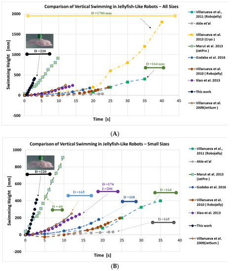
Figure 13.
Comparison of swimming jellyfish-like biomimetic soft robots. In the top graph (A) we have compared with other prototypes in the literature. In the bottom graph (B) we have excluded Cryo (2013) to obtain a zoomed version of the graph. All dimensions are in mm and the arrow lines depict the size of the robots. (Note: vertical movement vs time data of some jellyfish-like robots are not available or missing in publications, and therefore are not plotted here).
3.6. Peripheral Components and Future Works
We showed the necessary material, geometry and performance relationship of a small robotic jellyfish concentrating on actuation under load. The jellyfish inspired robotic system uses a compressed air source for actuation and needs provision for actuation source. Therefore, we tried to incorporate the whole actuation circuit and powering source into the jellyfish model. After a few design iterations, considering the size of our robot (Figure 14A), we designed and 3-D printed the outer casing for the model to protect the electronic circuit and other peripheral components. The diameter of the self-contained structure is 140 mm in diameter mm and 190 mm in height. Its total weight is 1.7 kg including all the electronics, battery, solenoid, canister and the silicone bell. One key component used here is a 12 g CO2 cylinder required to actuate the jellyfish untethered (Figure 14B). The peripheral components include rechargeable battery, valves, solenoids, voltage regulator, XBEE wireless communication module. However, the leakage of compressed gas and the limited gas amount in the CO2 cylinder allows the prototype to operate for only a few cycles. The current size of the onboard actuation unit is shown in Figure 14C. Further research and development will be directed towards the peripheral components, design (especially focusing on size and weight), directional movements, closed loop control, and to performing field tests.
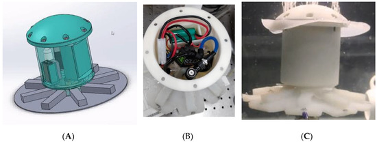
Figure 14.
Self-contained structure for FludoJelly: (A) CAD design of the self-contained design, (B) the prototype with circuits, battery, CO2 cylinder and electronics housed in the main body and (C) test in water of the self-contained jellyfish.
4. Conclusions
Inflatable structures found in nature were reviewed in this work. These structures provide some advantages for animals to survive or adapt in terrestrial or aquatic environments. Here, we developed elastomeric actuators with spring steels (soft pneumatic composite, SPC) and examine the performance, e.g., trajectory and bending characteristics, of the structure. The inflation of the actuators causes bending of the structure and enables flapping of the bell segment of the jellyfish-like robot, pushing the surrounding water out and creating a vortex. The jellyfish-like robot FludoJelly showed impressive actuation characteristics as well as swimming performance. The prototype has 220 mm in diameter, was able to carry a 100 g load and swim vertically at a speed of 160 mm/s when tested in a fish tank. This prototype has the fastest motion in ascending vertically compared to the previous robotic jellyfish. We tested the prototype at 50, 60 and 70 psi pressure magnitudes. In all cases, it showed less time for ascending as the input pressure was increased during the test in a fish tank. Cyclic testing of the prototype (for ascending and descending) inside a fish tank was also done for three cycles while carrying a 100 g load. The ascending motion was faster due to the flapping of the bell segments as well as buoyancy due to volume change, whereas the descending motion was relatively slower as it was sinking only due to gravity. To check the flapping characteristics of the bell segment, we secured the middle section of the FludoJelly and submerged it at specific heights in the water tank. We observed that as we increased the height, the deflection increased, and we obtained maximum normalized deformation of 59%. Slight variation in geometry such as thickness and air trapped in the elastomer could create unequal expansion of the chambers/actuators (Video S5 High Speed Camera 50 Psi Pressure 5x Slow Playback. mp4, supplementary). This was observed in some of the experiments during testing, which can be avoided by creating distinct air passages with increased thickness of the actuator wall during the construction of the SPC. A compressed gas source that lasts for a longer period of swimming will be addressed in our future work. Currently, the robot is operated while tethered. In order to change direction and swim in 3D, we will need to include additional pumps or valves to control different segments of the bell, which is left for future work. We determined the basic characteristics of the structure qualitatively and quantitatively. This was extremely useful in order for the next version of the robot to be fully autonomous and operated by onboard compressed gas. In addition, sensor integration and control will be the subjects of future research. Jellyfish species such as Aurelia aurita is one of the most efficient swimmers on the planet [47] and more work should be done to realize an underwater vehicle inspired by such species.
Supplementary Materials
The following are available online at https://www.mdpi.com/2218-6581/8/3/56/s1, Video S1 FludoJelly1, SPC actuators.mp4; Video S2 FludoJelly2 100 g payload.mp4; Video S3 Cyclic Swimming FludoJelly 60 psi 1X.mp4; Video S4 Height Deflection of the Bell 1.5X.mp4; Video S5 High Speed Camera 50 Psi Pressure 5x Slow Playback. mp4.
Author Contributions
Conceptualization, A.K. and Y.T.; Data curation, A.J.; Formal analysis, Y.T.; Funding acquisition, Y.T.; Investigation, A.J., A.K. and Y.T.; Methodology, A.J., A.K. and Y.T.; Project administration, Y.T.; Resources, Y.T.; Software, A.J. and A.K.; Supervision, Y.T.; Visualization, A.K.; Writing – original draft, A.K.; Writing – review & editing, A.J. and Y.T.
Funding
This work is supported by the Office of Naval Research (ONR), Young Investigator Program, under the grant number N00014-15-1-2503.
Acknowledgments
We would like to thank McKenna, program manager at ONR Biorobotics program. We would like to thank Shameek Kulkarni for designing CAD design and 3D printing of the peripheral components.
Conflicts of Interest
The authors declare no conflict of interest.
References
- Bar-Cohen, Y. Biomimetics—using nature to inspire human innovation. Bioinspir. Biomim. 2006, 1, P1–P12. [Google Scholar] [CrossRef] [PubMed]
- Jusufi, A.; Vogt, D.M.; Wood, R.J.; Lauder, G.V. Undulatory swimming performance and body stiffness modulation in a soft robotic fish-inspired physical model. Soft Robot. 2017, 4, 1–9. [Google Scholar] [CrossRef] [PubMed]
- Kim, H.-S.; Lee, J.-Y.; Chu, W.-S.; Ahn, S.-H. Design and Fabrication of Soft Morphing Ray Propulsor: Undulator and Oscillator. Soft Robot. 2017, 4, 49–60. [Google Scholar] [CrossRef] [PubMed]
- Lin, H.-T.; Leisk, G.G.; Trimmer, B. GoQBot: A caterpillar-inspired soft-bodied rolling robot. Bioinspir. Biomim. 2011, 6, 026007. [Google Scholar] [CrossRef] [PubMed]
- Rus, D.; Tolley, M.T. Design, fabrication and control of soft robots. Nature 2015, 521, 467–475. [Google Scholar] [CrossRef] [PubMed]
- Shepherd, R.F.; Stokes, A.A.; Nunes, R.; Whitesides, G.M. Soft machines that are resistant to puncture and that self seal. Adv. Mater. 2013, 25, 6709–6713. [Google Scholar] [CrossRef] [PubMed]
- Tolley, M.T.; Shepherd, R.F.; Mosadegh, B.; Galloway, K.C.; Wehner, M.; Karpelson, M.; Wood, R.J.; Whitesides, G.M. A resilient, untethered soft robot. Soft Robot. 2014, 1, 213–223. [Google Scholar] [CrossRef]
- Mosadegh, B.; Polygerinos, P.; Keplinger, C.; Wennstedt, S.; Shepherd, R.F.; Gupta, U.; Shim, J.; Bertoldi, K.; Walsh, C.J.; Whitesides, G.M. Pneumatic networks for soft robotics that actuate rapidly. Adv. Funct. Mater. 2014, 24, 2163–2170. [Google Scholar] [CrossRef]
- Sun, Y.; Song, Y.S.; Paik, J. Characterization of silicone rubber based soft pneumatic actuators. In Proceedings of the 2013 IEEE/RSJ International Conference on Intelligent Robots and Systems, Tokyo, Japan, 3–7 November 2013; pp. 4446–4453. [Google Scholar]
- Lu, X.; Xu, W.; Li, X. Concepts and simulations of a soft robot mimicking human tongue. In Proceedings of the 2015 6th International Conference on Automation, Robotics and Applications (ICARA), Queenstown, New Zealand, 17–19 February 2015; pp. 332–336. [Google Scholar]
- Marchese, A.D.; Katzschmann, R.K.; Rus, D. A recipe for soft fluidic elastomer robots. Soft Robot. 2015, 2, 7–25. [Google Scholar] [CrossRef] [PubMed]
- Shepherd, R.F.; Ilievski, F.; Choi, W.; Morin, S.A.; Stokes, A.A.; Mazzeo, A.D.; Chen, X.; Wang, M.; Whitesides, G.M. Multigait soft robot. Proc. Natl. Acad. Sci. USA 2011, 108, 20400–20403. [Google Scholar] [CrossRef] [PubMed]
- Wehner, M.; Truby, R.L.; Fitzgerald, D.J.; Mosadegh, B.; Whitesides, G.M.; Lewis, J.; Wood, R.J. An integrated design and fabrication strategy for entirely soft, autonomous robots. Nature 2016, 536, 451–455. [Google Scholar] [CrossRef] [PubMed]
- Katzschmann, R.K.; Marchese, A.D.; Rus, D. Hydraulic autonomous soft robotic fish for 3D swimming. In Experimental Robotics; Springer: Berlin, Germany, 2016; Volume 109, pp. 405–420. [Google Scholar]
- Park, Y.-L.; Chen, B.-R.; Pérez-Arancibia, N.O.; Young, D.; Stirling, L.; Wood, R.J.; Goldfield, E.C.; Nagpal, R. Design and control of a bio-inspired soft wearable robotic device for ankle-foot rehabilitation. Bioinspir. Biomim. 2014, 9, 016007. [Google Scholar] [CrossRef] [PubMed]
- Colin, S.P.; Costello, J.H. Morphology, swimming performance and propulsive mode of six co-occurring hydromedusae. J. Exp. Biol. 2002, 205, 427–437. [Google Scholar] [PubMed]
- AquaJellies 2.0 Autonomous behaviour in a collective. 2017. Available online: https://www.festo.com/group/en/cms/10227.htm (accessed on 30 July 2017).
- Xiao, J.; Duan, J.; Yu, J. Design and implementation of a novel biomimetic robotic jellyfish. In Proceedings of the IEEE International Conference on Robotics and Biomimetics (ROBIO), Shenzhen, China, 12–14 December 2013; pp. 988–993. [Google Scholar]
- Villanueva, A.; Bresser, S.; Chung, S.; Tadesse, Y.; Priya, S. Jellyfish inspired unmanned underwater vehicle. In Electroactive Polymer Actuators and Devices (EAPAD) 2009, Proceedings of the SPIE Smart Structures and Materials + Nondestructive Evaluation and Health Monitoring, San Diego, CA, USA, 8–12 March 2009; SPIE: Bellingham, WA, USA, 2009; Volume 7287, p. 7287. [Google Scholar]
- Villanueva, A.; Smith, C.; Priya, S. A biomimetic robotic jellyfish (Robojelly) actuated by shape memory alloy composite actuators. Bioinspir. Biomim. 2011, 6, 036004. [Google Scholar] [CrossRef] [PubMed]
- Tadesse, Y.; Villanueva, A.; Haines, C.; Novitski, D.; Baughman, R.; Priya, S. Hydrogen-fuel-powered bell segments of biomimetic jellyfish. Smart Mater. Struct. 2012, 21, 045013. [Google Scholar] [CrossRef]
- Villanueva, A.A.; Marut, K.J.; Michael, T.; Priya, S. Biomimetic autonomous robot inspired by the Cyanea capillata (Cyro). Bioinspir. Biomim. 2013, 8, 046005. [Google Scholar] [CrossRef] [PubMed]
- Yang, Y.; Ye, X.; Guo, S. A new type of jellyfish-like microrobot. In Proceedings of the 2007 IEEE International Conference on Integration Technology, Shenzhen, China, 20–24 March 2007; pp. 673–678. [Google Scholar]
- Nawroth, J.C.; Lee, H.; Feinberg, A.W.; Ripplinger, C.M.; McCain, M.L.; Grosberg, A.; Dabiri, J.O.; Parker, K.K. A tissue-engineered jellyfish with biomimetic propulsion. Nat. Biotechnol. 2012, 30, 792–797. [Google Scholar] [CrossRef] [PubMed]
- Frame, J.; Lopez, N.; Curet, O.; Engeberg, E.D. Thrust force characterization of free-swimming soft robotic jellyfish. Bioinspir. Biomim. 2018, 13, 064001. [Google Scholar] [CrossRef]
- Smith, C.; Villanueva, A.; Joshi, K.; Tadesse, Y.; Priya, S. Working principle of bio-inspired shape memory alloy composite actuators. Smart Mater. Struct. 2010, 20, 012001. [Google Scholar] [CrossRef]
- Tadesse, Y.; Brennan, J.; Smith, C.; Long, T.E.; Priya, S. Synthesis and characterization of polypyrrole composite actuator for jellyfish unmanned undersea vehicle. In Electroactive Polymer Actuators and Devices (EAPAD) 2009, Proceedings of the SPIE Smart Structures and Materials + Nondestructive Evaluation and Health Monitoring, San Diego, CA, USA, 7–11 March 2010; SPIE: Bellingham, WA, USA, 2010; Volume 7642, p. 7642. [Google Scholar]
- Yeom, S.-W.; Oh, I.-K. A biomimetic jellyfish robot based on ionic polymer metal composite actuators. Smart Mater. Struct. 2009, 18, 085002. [Google Scholar] [CrossRef]
- HARLAN, R. 10 Weird Self-Inflating Animal Species. 2014. Available online: http://listverse.com/2014/01/03/10-weird-self-inflating-animal-species/ (accessed on 30 July 2017).
- Quin Marshall “Get Down In Jellytown!”. Available online: https://quinsprogress.com/2014/02/ (accessed on 5 June 2019).
- Australian Red-eyed Tree Frog (Litoria chloris). Available online: https://en.wikipedia.org/wiki/Vocal_sac#/media/File:Litoria_chloris_calling.jpg (accessed on 5 June 2019).
- Ilievski, F.; Mazzeo, A.D.; Shepherd, R.F.; Chen, X.; Whitesides, G.M. Soft robotics for chemists. Angew. Chem. 2011, 123, 1930–1935. [Google Scholar] [CrossRef]
- Almubarak, Y.; Tadesse, Y. Twisted and coiled polymer (TCP) muscles embedded in silicone elastomer for use in soft robot. Int. J. Intell. Robot. Appl. 2017, 1, 352–368. [Google Scholar] [CrossRef]
- Onal, C.D.; Chen, X.; Whitesides, G.M.; Rus, D. Soft mobile robots with on-board chemical pressure generation, In Robotics Research; Springer: Berlin, Germany, 2017; Volume 100, pp. 525–540. [Google Scholar]
- Marchese, A.D.; Onal, C.D.; Rus, D. Autonomous soft robotic fish capable of escape maneuvers using fluidic elastomer actuators. Soft Robot. 2014, 1, 75–87. [Google Scholar] [CrossRef] [PubMed]
- Marchese, A.D.; Rus, D. Design, kinematics, and control of a soft spatial fluidic elastomer manipulator. Int. J. Robot. Res. 2016, 35, 840–869. [Google Scholar] [CrossRef]
- Villanueva, A.; Vlachos, P.; Priya, S. Flexible margin kinematics and vortex formation of Aurelia aurita and Robojelly. PLoS ONE 2014, 9, e98310. [Google Scholar] [CrossRef] [PubMed]
- Douglas Brown, Tracker: Open source video analysis and modeling tool, Available online:. Available online: http://physlets.org/tracker/ (accessed on 18 February 2018).
- Giorgio-Serchi, F.; Weymouth, G.D. Underwater soft robotics, the benefit of body-shape variations in aquatic propulsion. In Soft Robotics: Trends, Applications and Challenges; Springer: Berlin, Germany, 2017; Volume 17, pp. 37–46. [Google Scholar]
- Renda, F.; Serchi, F.G.; Boyer, F.; Laschi, C. Structural dynamics of a pulsed-jet propulsion system for underwater soft robots. Int. J. Adv. Robot. Syst. 2015, 12, 68. [Google Scholar] [CrossRef]
- Giorgio-Serchi, F.; Lidtke, A.K.; Weymouth, G.D. A soft aquatic actuator for unsteady peak power amplification. IEEE/ASME Trans. Mechatron. 2018, 23, 2968–2973. [Google Scholar] [CrossRef]
- Keithly, D.; Whitehead, J.; Voinea, A.; Horna, D.; Hollenberg, S.; Peck, M.; Pikul, J.; Shepherd, R.F. A cephalopod-inspired combustion powered hydro-jet engine using soft actuators. Extreme Mech. Lett. 2018, 20, 1–8. [Google Scholar] [CrossRef]
- Salazar, R.; Fuentes, V.; Abdelkefi, A. Classification of biological and bioinspired aquatic systems: A review. Ocean Eng. 2018, 148, 75–114. [Google Scholar] [CrossRef]
- Akle, B.; Najem, J.; Leo, D.; Blottman, J. Design and development of bio-inspired underwater jellyfish like robot using ionic polymer metal composite (IPMC) actuators. In Electroactive Polymer Actuators and Devices (EAPAD) 2011, Proceedings of the SPIE Smart Structures and Materials + Nondestructive Evaluation and Health Monitoring, San Diego, CA, USA, 6–10 March, 2011; SPIE: Bellingham, WA, USA, 2011; Volume 7976, p. 7976. [Google Scholar]
- Godaba, H.; Li, J.; Wang, Y.; Zhu, J. A soft jellyfish robot driven by a dielectric elastomer actuator. In IEEE Robot. Auto. Lett. 2016, 1, 624–631. [Google Scholar] [CrossRef]
- Marut, K.; Stewart, C.; Michael, T.; Villanueva, A.; Priya, S. A jellyfish-inspired jet propulsion robot actuated by an iris mechanism. Smart Mater. Struct. 2013, 22, 094021. [Google Scholar] [CrossRef]
- Gemmell, B.J.; Costello, J.H.; Colin, S.P.; Stewart, C.J.; Dabiri, J.O.; Tafti, D.; Priya, S. Passive energy recapture in jellyfish contributes to propulsive advantage over other metazoans. Proc. Natl. Acad. Sci. USA 2013, 110, 17904–17909. [Google Scholar] [CrossRef] [PubMed]
© 2019 by the authors. Licensee MDPI, Basel, Switzerland. This article is an open access article distributed under the terms and conditions of the Creative Commons Attribution (CC BY) license (http://creativecommons.org/licenses/by/4.0/).