Article

Upside-Down Robots: Modeling and Experimental Validation of Magnetic-Adhesion Mobile Systems

1
Department of Engineering and Architecture, University of Trieste, 34100 Trieste, Italy
2
Polytechnic Department of Engineering and Architecture, University of Udine, 33100 Udine, Italy
3
Faculty of Science and Technology, Free University of Bozen-Bolzano, 39100 Bolzano, Italy
*
Author to whom correspondence should be addressed.
Robotics 2019, 8(2), 41; https://doi.org/10.3390/robotics8020041
Submission received: 30 March 2019 / Revised: 23 May 2019 / Accepted: 29 May 2019 / Published: 31 May 2019
(This article belongs to the Special Issue Advances in Italian Robotics)

Abstract

:
In this paper, we present the modeling and validation of a new family of climbing robots that are capable of adhering to vertical surfaces through permanent magnetic elements. The robotic system is composed of two modules, the master and the follower carts, which are arranged in a sandwich configuration, with the surface to climb interposed between them. Thanks to this configuration, the mobile robot can climb even nonferromagnetic and curved surfaces; moreover, the master cart is capable of freely moving on the floor by detaching from the follower. In this paper, we propose the mathematical modeling, simulation, and experimental validation of this kind of robots, with particular focus on the transitions between floor and climbing motion.

1. Introduction

In recent years, mobile robots have become increasingly common and have found applications in several different fields. For example, they are employed in the industrial and commercial field for material handling and stocking [1], in agriculture for inspection and monitoring [2,3], in civil contexts for cleaning operations [4], surveillance [5], proximal sensing [6], and service tasks [7], as well in space exploration and hazardous environments [8,9,10].
In this context, a special family of mobile robots is that of robots capable of climbing on wall surfaces. Climbing robots are often adopted for inspection and safety in process industries, maintenance, and diagnosis in civil constructions, as well as in places where the presence of a human can be very expensive or dangerous due to a hostile environment. Climbing robots have to be lightweight, carry sensors and instrumentation, and have to be provided with a proper locomotion and adhesion system with respect to the surface they have to climb. Several different adhesion methods were investigated and tested in the literature: vacuum or suction cups, gripping to the surface, bioinspired adhesion methods, and magnetic adherence [11].
The use of suction force, generated through the Venturi Principle or by means of vacuum pumps, is the most common approach to provide adhesion to a climbing robot. Vacuum technology is usually light, easy to control, and allows to climb over arbitrary surfaces. The main drawbacks are the required time to generate the vacuum, the problem of carrying suction pumps on board, and the limits given by possible surface irregularities. Examples can be found in References [12,13,14].
Another approach for climbing robots is gripping to the surface by means of claws, limb extremities, or gripping systems. This method allows to climb more irregular surfaces, such as in References [15,16].
Bioinspired adhesive methods are another solution to guarantee adhesion to wall-climbing robots. These technologies are based on the use of patches of microscopic hairs that ensure dry adhesion thanks to Van der Waals forces, as on the legs of several insects, geckos, or spiders [17]. Examples of bioinspired adhesive-climbing robots can be found in References [18,19,20].
Magnetic force is another principle for creating adhesion in wall-climbing robots. Permanent magnets have several advantages with respect to other adhesion systems: they are inherently reliable, and low cost and no energy are required for adhesion [21]. Magnetic-adhesion climbing systems work very well when the surfaces to climb are composed of ferromagnetic materials. Robotic systems can either be equipped with permanent magnets to adhere onto the surface combined with wheels to move along it [22,23], or can adopt magnetic wheels that combine locomotion and adhesion [24,25]. In the first case, the presence of an air gap has to be taken into account; thus, the force of adhesion is reduced. On the other hand, magnetic wheels provide higher adhesion forces since they are in direct contact with the ferromagnetic surface. Another approach of wall climbing with the principle of magnetic adhesion is given by crawler-based robots [26,27,28]. Magnetic adhesion wall-climbing robots were adopted in several applications, such as in nondestructive tests [22,23], or for the inspection of ship hulls [27,28,29].
If the surface onto which wall-climbing robots have to adhere is nonferromagnetic, a possible solution to using magnetic-adhesion systems is to adopt a robot composed of two modules: a master and a follower cart. They are arranged in a sandwich configuration, with the surface to climb interposed between them. Thanks to this approach, the robotic system can climb even nonferromagnetic and curved surfaces; moreover, the master cart is capable of freely moving on the floor by detaching itself from the follower. The added advantage is that this system does not require power, allowing for more compact, lighter, and cheaper robots; indeed, contrary to some proposed concept that does not rely magnets (e.g., References [12,13,17,30]), this method is passive and does not continuously require power. No examples of wall-climbing robots based on magnetic adhesion and composed of two coupled subsystems can be found in the present literature. There exist some industrial examples of these sandwich robots, e.g., the Windowmate robot produced by RF Co. (http://www.mywindowmate.com), and Windoro produced by Iishim Global Co., Ltd. (http://www.mywindoro.com). These systems require an operator to manually detach the two modules.
The main contributions of this work can be summarized as follows:
  • mathematical modeling of a class of magnetic-adhesion mobile robots that are capable of climbing walls thanks to a sandwich configuration. Furthermore, this design allows the master robot to autonomously detach itself from the follower, which is a novel contribution to the state of the art;
  • numerical analysis through simulations, taking into account the interaction between the two carts, and between the robot and the support sheet (planar driving, behavior during detachment, and driving on a curved sheet);
  • experimental validation of the prototype of an upside-down robot, both in the detachment phase as well as on the curved surface.
Indeed, to the best of the authors’ knowledge, the permanent-magnet sandwich-configuration robot presented in this paper is the first that is capable to passively climb on nonferromagnetic surfaces, while at the same time being able to autonomously detach itself from the follower cart when needed.
This paper is an extended version of a preliminary work presented at the Second International Conference of IFToMM Italy, IFIT 2018 [31]; it is organized as follows: in Section 2, the architecture of the robot is briefly described, in Section 3 the mathematical model is presented, and in Section 4 numerical implementation is described along with the main simulation results; experiment validation is presented in Section 5; finally, Section 6 highlights the conclusions and possible future developments of this work.

2. Robot Architecture

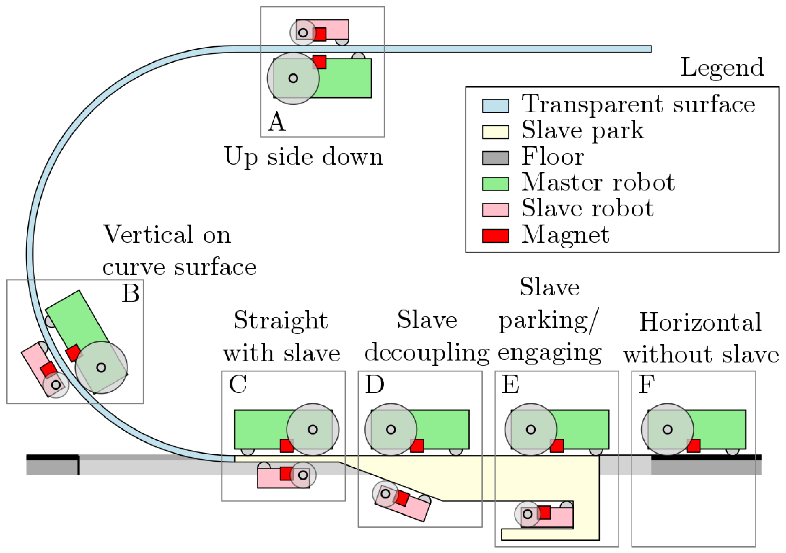
The system presented in this paper consists of a robot that is able to crawl and drive on nonmagnetic thin supports, arbitrarily oriented in space. The system, which is illustrated in Figure 1, is composed of two modules, the master and the slave or follower, which are kept magnetically coupled through permanent magnets at either side of the support sheet. This architecture allows for a high degree of mobility through the design of tracks and planes that let the robot climb vertically or even drive upside down. Furthermore, the robot can autonomously discard the slave cart in special slave park areas in order to be free to drive along the horizontal plane as a normal mobile robot would.
Envisioned applications of this type of architecture include highly compact storage environments such as greenhouses [32] or pharmaceutical warehouses, where complex transfer operations need to be carried out [33]. In these environments, pick-and-place operations and subsequent transfer to remote locations in the industrial floor are usually needed. Normally, these tasks would require at least two manipulators (serial, Delta, or Scara), one at the origin and one at the destination, along with a mobile system, e.g., a mobile robot or rover. On the other hand, the approach here only presented calls for a single mobile robot with climbing capabilities, which can possibly translate into a decrease in cost and complexity of the entire installation.
The proposed system can be described as the interaction between three entities, a robot, a passive cart, and the environment, in the form of the support sheet. These actors exchange magnetic forces, contact forces, and friction, and are subject to gravity. We can break down this complex interaction by analyzing the limited number of possible situations that the robot can encounter:
  • upside-down driving phase (A);
  • curved-surface driving phase (B);
  • slave-decoupling phase (D); and
  • slave parking/engaging (E).
Other phases exist that are either a composition or transitions between pairs of the above; furthermore, Phases C and F are considered trivial once the other phases are verified and, as such, need not be discussed in detail. In Figure 2, a diagram of the main phases and main constituents of the system is illustrated.
In the paper, the master robot is generally indicated using the letter “r”, while the slave or follower is indicated with “f”. The side on which the master drives is called master surface, whereas the opposite is referred to as slave surface. The model geometry is considered as 2D throughout the article, while the model itself can be considered 1D, only considering the misalignment between the master and slave. In order for the system to work correctly, the following conditions have to be satisfied:
  • the master robot always has to be pressed against the master surface;
  • the master robot has to be able to drive away from the influence of the magnetic field of the slave during parking; and
  • the slave robot has to always be pressed against the slave surface except when parked.
In the following section, the model is presented, starting from the magnetic model, and continuing with the pseudostatic model of the robotic system in its main phases, namely, planar and curved-surface driving, and parking.

3. Mathematical Model

In this section we present the mathematical model of the robot. We describe the model of the magnetic field and of the robot in the case of a planar surface, a cylindrical surface, and during parking and engaging. Finally, we analyze traction and the contact forces. In this preliminary work, a quasistatic model of the robotic system was taken into account.

3.1. Magnetic Model

Two magnetic dipole moments, m r and m f , related to the master robot and follower, respectively, and separated by a vector r , interact by exchanging a magnetic force F m and torque τ m [34], as follows:
F m = m f · B r τ m = m f × B r ,
where magnetic flux density B r of the first dipole moment is defined as follows:
B r = μ 4 π 3 r m r · r r 5 m r r 3 ,
where μ is magnetic permeability. Let the unit vector of r be r ^ = r / r ; using a truncated Taylor series, a more manageable form for the force was developed by Yung et al. [35]:
F m = 3 μ 4 π r 4 ( r ^ × m r ) × m f + r ^ × m f ) × m r 2 r ^ ( m r · m f ) + 5 r ^ ( ( r ^ × m r ) · ( r ^ × m f ) ) .
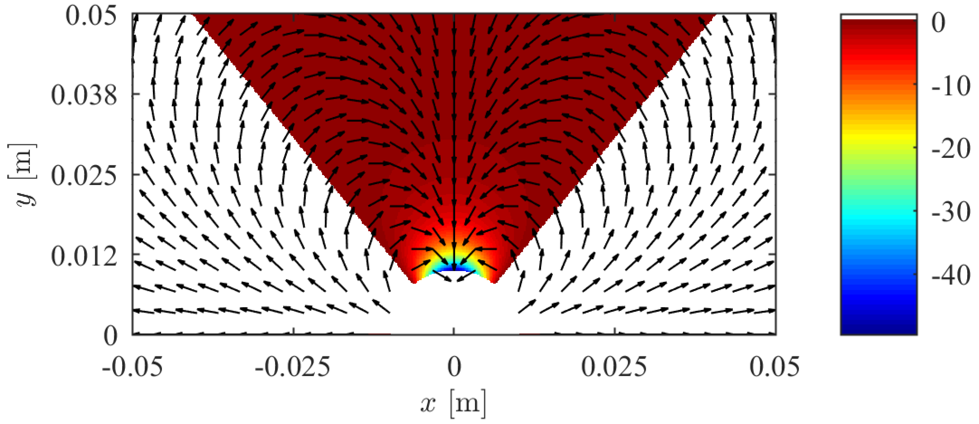
Despite this formulation being approximate, in that it neglects the higher-order Taylor terms, it is sufficiently adherent to the magnetic behavior found in the problem at hand. In Figure 3, the interaction between the two dipoles is shown.

3.2. Planar-Surface Model

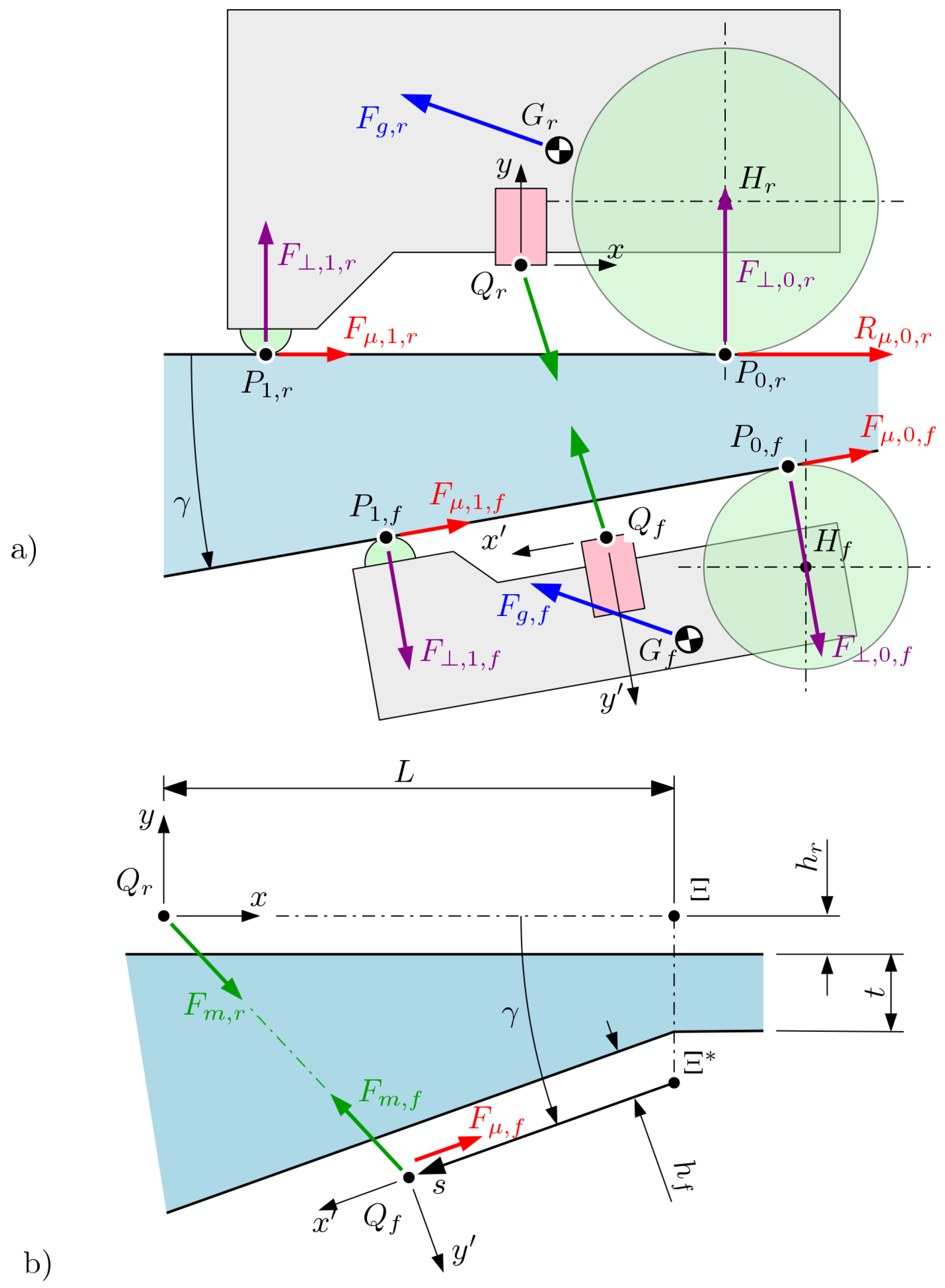
In the following, we describe the quasistatic model of the robotic system in the case of planar surface. The most fundamental geometric configuration is that in which the master and slave surfaces are straight and parallel to one another (see Phases A and C); for the sake of generality, we model the surfaces as not necessarily parallel, thus defining the inclination angle γ of the slave surface with respect to the master plane orientation. This can be seen in Figure 4. Based on the same figure, we assume the frame of reference as centered in point Q r and integral to the master robot. It is also assumed that the geometry of the master and slave actors is entirely known, and is defined by the following parameters: the contact point of the rear wheel P r , 0 , of the front one P r , 1 , the axis of the rear wheel H r , center of mass G r , and mass m r . It is useful to note that, in principle, the points of contact for cylindrical wheels depend on the shape of the surface; in case of a planar surface, their coordinates are trivial to calculate. The geometry and mechanical characteristics of the slave can be defined in the same way with respect to the slave frame of reference ( x , y ) in Q f by the following variables: P f , 0 , P f , 1 , H f , G f and m f . The pose of the slave with respect to the master can be defined by four variables: the two coordinates of point Ξ * , angle γ , and position s along the slave surface.
We consider, referring to Figure 4, quantities L, h r , t and h f the travel of the robot from the beginning of the ramp, the height of the magnet of the robot, the thickness of the support sheet before the ramp, and the height of the magnet of the follower, respectively; from geometrical considerations,
Ξ * = Q r + L 0 + 0 h r + 0 t + 0 h f cos γ ,
from which follows
Q f = Ξ * + s cos γ sin γ .
In order to determine the pose of the slave in the master frame of reference ( x , y ) , the following transformation matrix can be defined:
T = cos π + γ sin π + γ Q f , x sin π + γ cos π + γ Q f , y 0 0 1 ,
which allows the following:
P f , 0 = TP f , 0 P f , 1 = TP f , 1 H f = TH f G f = TG f .
At this point, from Equations (1)–(3), we can write F m , f f m r , m f , r and, similarly, F m , r , τ m , f and τ m , r . We introduce force of gravity F g , f = m f g ; if we call F , 0 , f and F , 1 , f the normal contact forces between the wheels of the slave and the slave surface, we can express the force equilibrium along direction y ^ , and the moment equilibrium, as follows:
1 1 M F 0 f M F 1 f F , 0 , f F , 1 , f = F g , f · y ^ F m , f · y ^ τ m , f · z ^ M F g ,
where, introducing z ^ = x ^ × y ^ , it occurs that M F 0 f = P 0 , f Q f × y ^ · z ^ , M F 1 f = P 1 , f Q f × y ^ · z ^ and M F g = P 1 , f Q f × F g , f · z ^ , which are the moments generated by forces F , 0 , f , F , 1 , f , and F g , f . The solution of the linear system in Equation (7) yields contact forces F , 0 , f and F , 1 , f , which can be used to compute the forces caused by friction, according to Coulomb’s law, in dynamic conditions:
F μ , 0 , f = μ 0 , f F , 0 , f F μ , 1 , f = μ 1 , f F , 1 , f x ^
where μ 0 , f and μ 1 , f are the equivalent dynamic coefficients of friction between the ground and, respectively, the wheel and the front skid of the follower. Variable s determines the position of the slave along the slave surface, as shown in Figure 4b, since the follower is not rigidly connected to the master. In fact, location s e q , where the slave is stable, is determined by the equilibrium of the external forces (magnetic, gravity, and friction) in direction x ^ of the support surface, as follows:
F ε f s e q = x ^ · F m , f + F g , f + F f , μ , 0 + F f , μ , 1 = 0 .
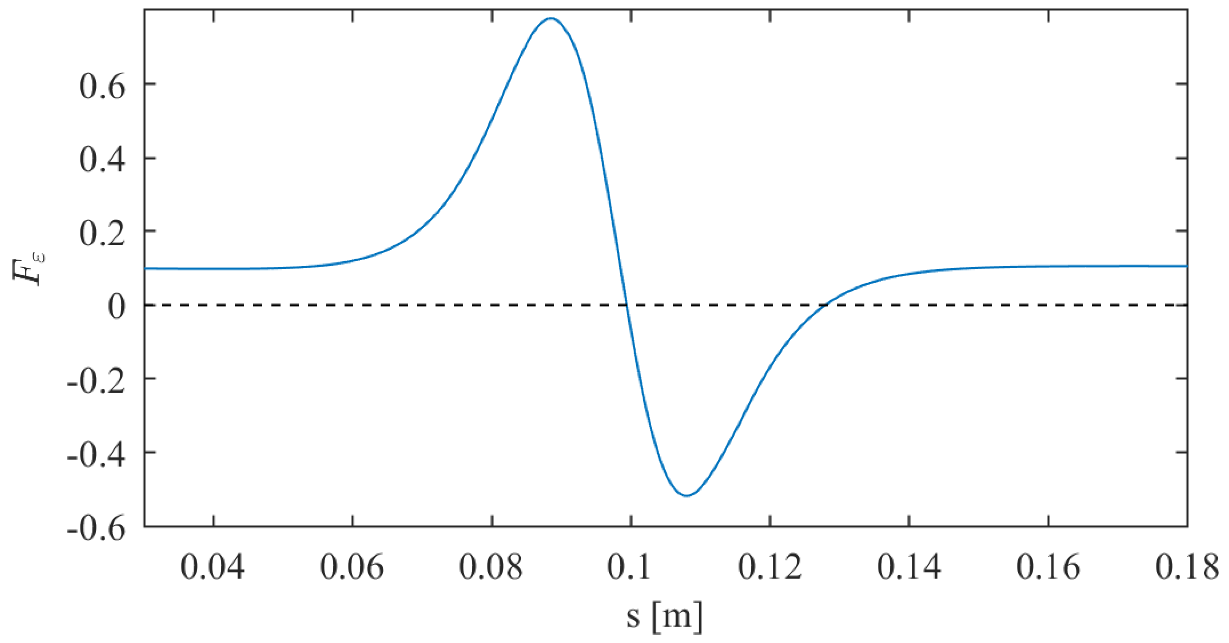
It is important to note that, while gravity force F g , f is constant, magnetic force F m , f as well as friction F f , μ , 0 and F f , μ , 1 depend on s, which renders Equation (8) implicit. In order to solve it, thus finding equilibrium point s e q , numerical methods have to be used. In Figure 5, the behavior of F ε ( s ) is plotted.
Once the location of the slave is known, the F m , r force vector can be calculated for the master robot, as well as F g , r . Hence, the force equilibrium can be stated as A r X r = B r , as follows:
A r = F ^ 0 r · x ^ F ^ 1 r · x ^ F ^ μ 1 r · x ^ R ^ μ 0 r · x ^ F ^ 0 r · y ^ F ^ 1 r · y ^ F ^ μ 1 r · y ^ R ^ μ 0 r · y ^ 0 μ r 1 1 0 M F 0 r M F 1 r M F μ 1 r M R μ 0
B r = F g + F m r · x ^ F g + F m r · y ^ 0 G r Q r × F g · z ^ τ m r · z ^
X r = F 0 r F 1 r F μ 1 R μ 0
where M F 0 r = P 0 r Q r × F ^ 0 r · z ^ , M F 1 r = P 1 r Q r × F ^ 1 r · z ^ , M F μ 1 r = P 1 r Q r × F ^ μ 1 r · z ^ and M R μ 0 = P 0 r Q r × R ^ μ 0 · z ^ . One should note that unit vectors F ^ 0 r , F ^ 1 r , F ^ μ 1 r and R ^ μ 0 are known based on the geometry of the contact surface.

3.3. Cylindrical Surfaces

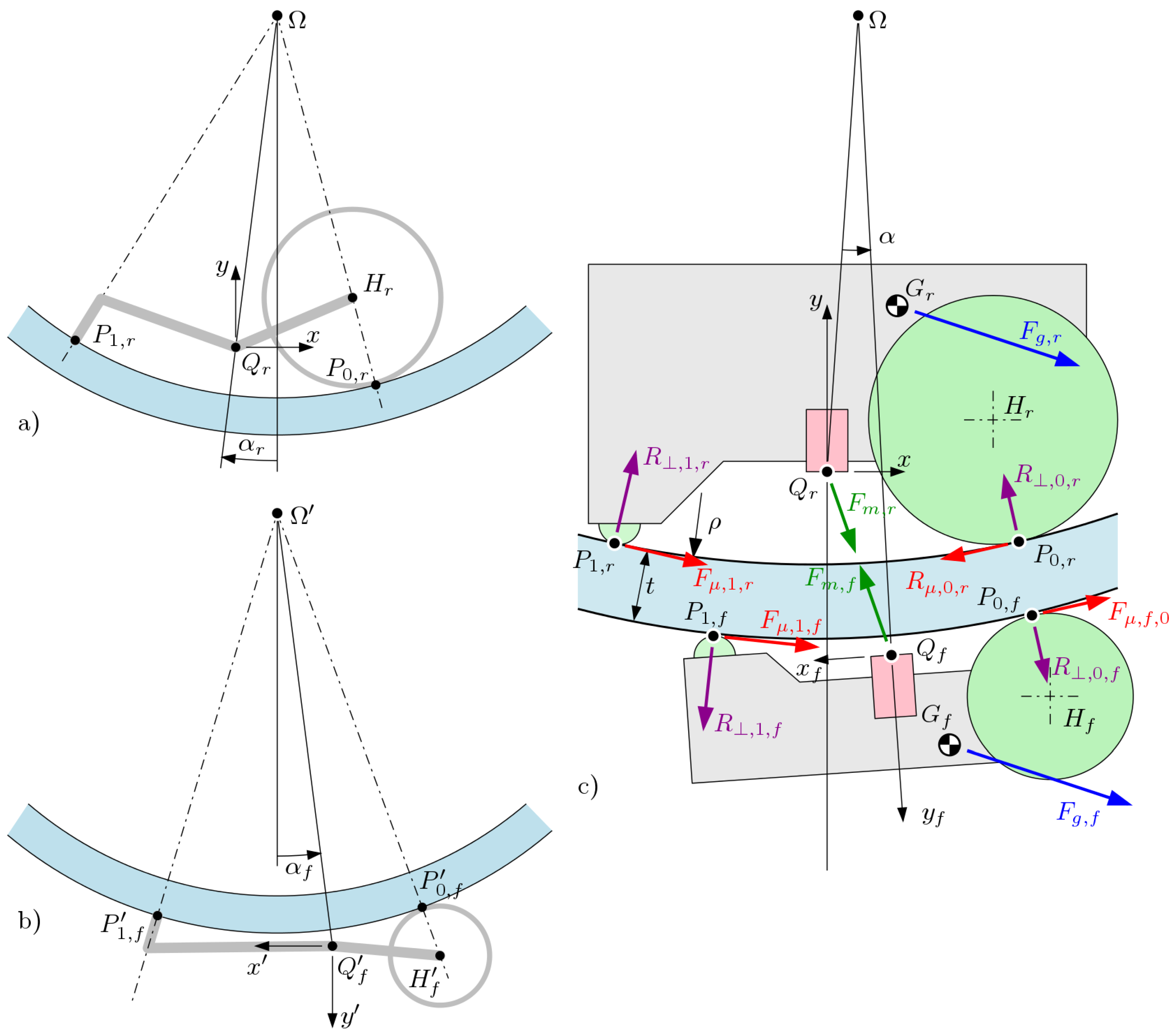
Similarly to the case of planar surfaces described in Section 3.2, by referring to Figure 6, we assume that frame of reference ( x , y ) is centered on Q r and aligned with the master robot. Contrary to the planar case, when the support surfaces are cylindrical, determining the position of the contact points of the wheels is less trivial. However, based on Figure 6, if we consider the front wheel or skid to be pointlike and described by P 1 , r , then, through simple geometrical considerations, projection point Ω can be calculated of the axis of the support surfaces; this allows remaining contact point P 0 , r to be located. If the frame of reference is ( x , y ) , then the same considerations apply to the slave for points P 0 , f and P 1 , f , and allow the determination of Ω .
The pose of the slave with respect to the master frame of reference is given by the geometry of the surfaces (i.e., thickness t and radius ρ ) and by angle α that constitutes the misalignment between the master and the slave, as shown in Figure 6c. In fact, in this case, variable α determines the position of the slave along the cylindrical surface in relation to the master. At this point, it is possible to write the transformation matrix from slave frame of reference ( x , y ) to master ( x , y ) :
T = 1 0 Ω r , x 0 1 Ω r , y 0 0 1 cos β sin β 0 sin β cos β 0 0 0 1 1 0 Ω f , x 0 1 Ω f , y 0 0 1 ,
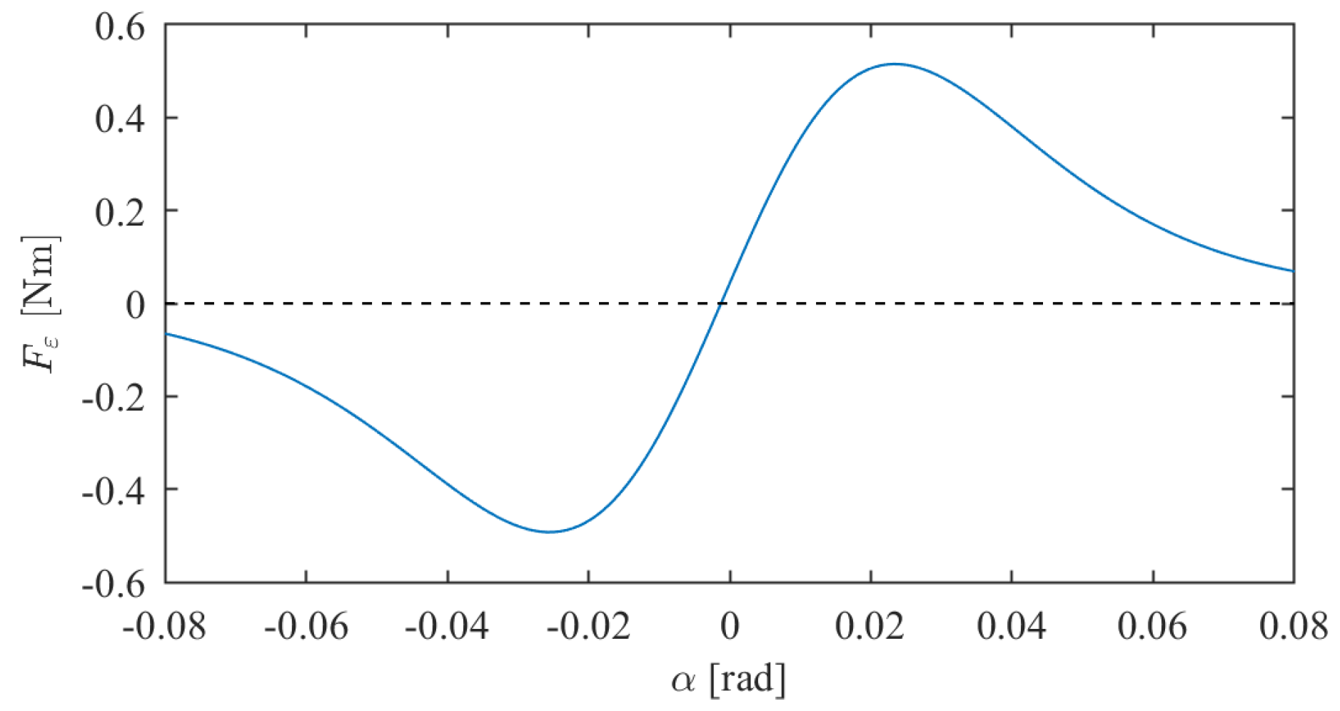
where β = π + α r α f . Therefore, using Equation (7), we can determine P f , 0 , P f , 1 , H f and G f in the ( x , y ) frame. In order to determine the equilibrium location of the slave robot, we introduce virtual force F ε , f , which is applied to point Q f . The slave robot is in equilibrium when F ε , f ( α e q ) = 0 . The linear system is defined as follows:
A f X f = B f
A f = F ^ 0 f · y ^ F ^ 1 f · y ^ F ^ μ 0 f · y ^ F ^ μ 1 f · y ^ F ^ ε f · y ^ F ^ 0 f · x ^ F ^ 1 f · x ^ F ^ μ 0 f · x ^ F ^ μ 1 f · x ^ F ^ ε f · x ^ μ 0 f 0 1 0 0 0 μ 1 f 0 1 0 M F 0 f M F ^ 1 f M F ^ μ 0 f M F ^ μ 1 f 0
B f = F m f + F g · y ^ F m f + F g · x ^ 0 0 τ m f M F g
X = F 0 f F 1 f F μ 0 f F μ 1 f F ε f
where the moments are M F ^ 0 f = P f 0 Q f × F ^ 0 f · z ^ , M F ^ 1 f = P f 1 Q f × F ^ 1 f · z ^ , M F ^ μ 0 f = P 0 f Q f × F ^ μ 0 f · z ^ , M F ^ μ 1 f = P f 1 Q f × F ^ μ 1 f · z ^ and M F g = G f Q f × F g · z ^ .
Solution X = A 1 B of the system, defined in Equation (10), yields information on the forces acting on the slave robot. The behavior of F ε f α can be seen in Figure 7; hence, point α e q , where the F ε f α line intersects with the dashed line, corresponds to equilibrium. The proper solution can be achieved by numerical methods.
Similarly to the case of planar surface, once the slave robot pose is known, it is possible to calculate the forces acting on the master, that is, F m , r . Contact forces can be calculated by balance, as for the planar case. Referring to Equations (11)–(13) related to the planar-surface case, the system for cylindrical surfaces is defined as A r X r = B r , with the only difference being the contact and friction force vectors.

3.4. Slave Parking/Engaging

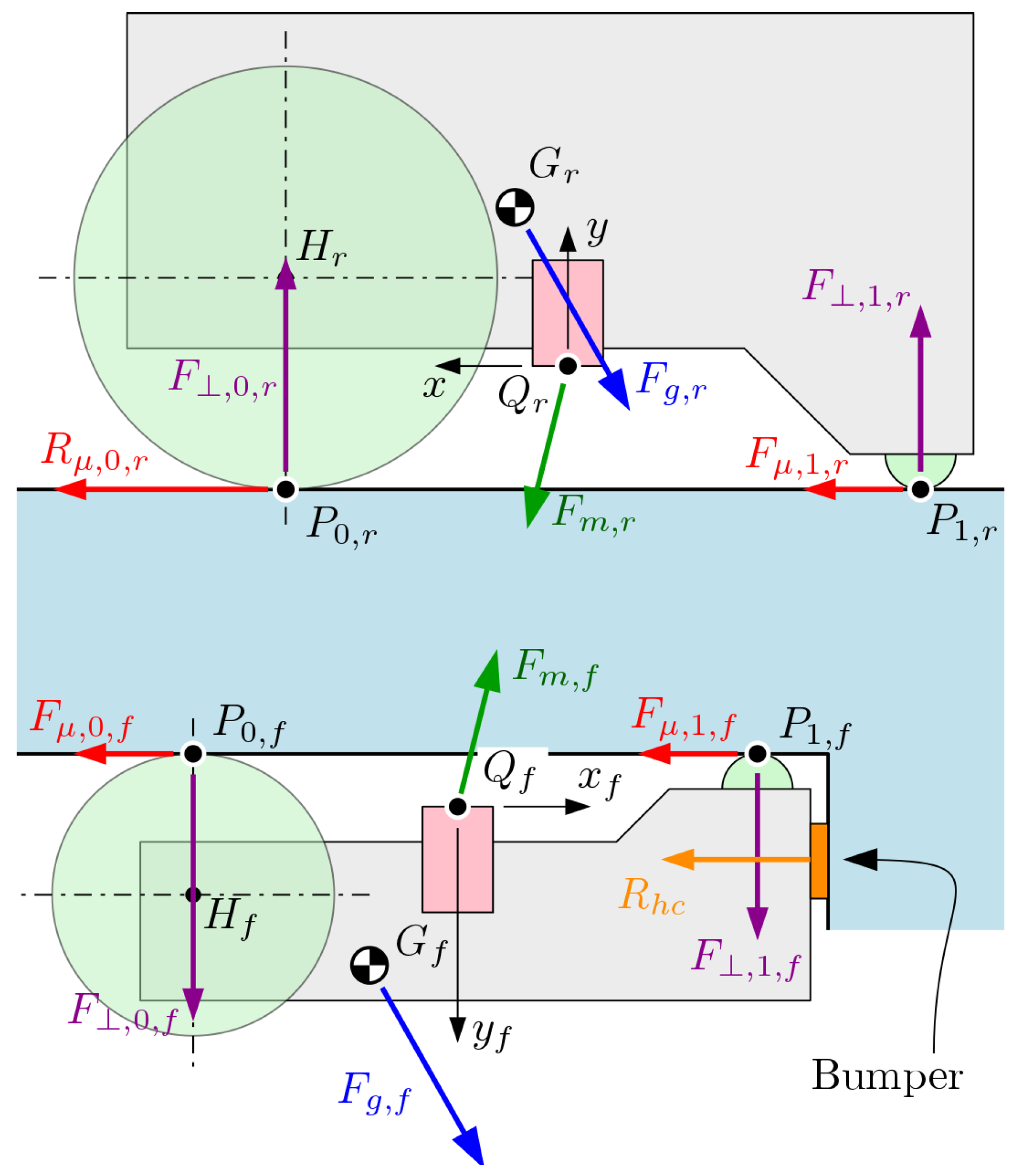
The last phase that is worth mentioning is the coupling and decoupling of the master from the slave. Referring to Figure 2, the reader can note that, during this procedure, the slave enters a slot on the support structure and is prevented to move horizontally. In fact, in Figure 8, a bumper is highlighted that implements this constraint. In order for the procedure to work, two prerequisites have to be satisfied:
  • Magnetic force F m , r acting on the master robot should be sufficiently small to allow it to drive away; indeed, maximum traction force F t r , 0 , r = μ w h e e l F , 0 , r of the master robot should be larger than R μ , 0 , r , i.e., the reaction force produced by the external forces on the wheel contact point;
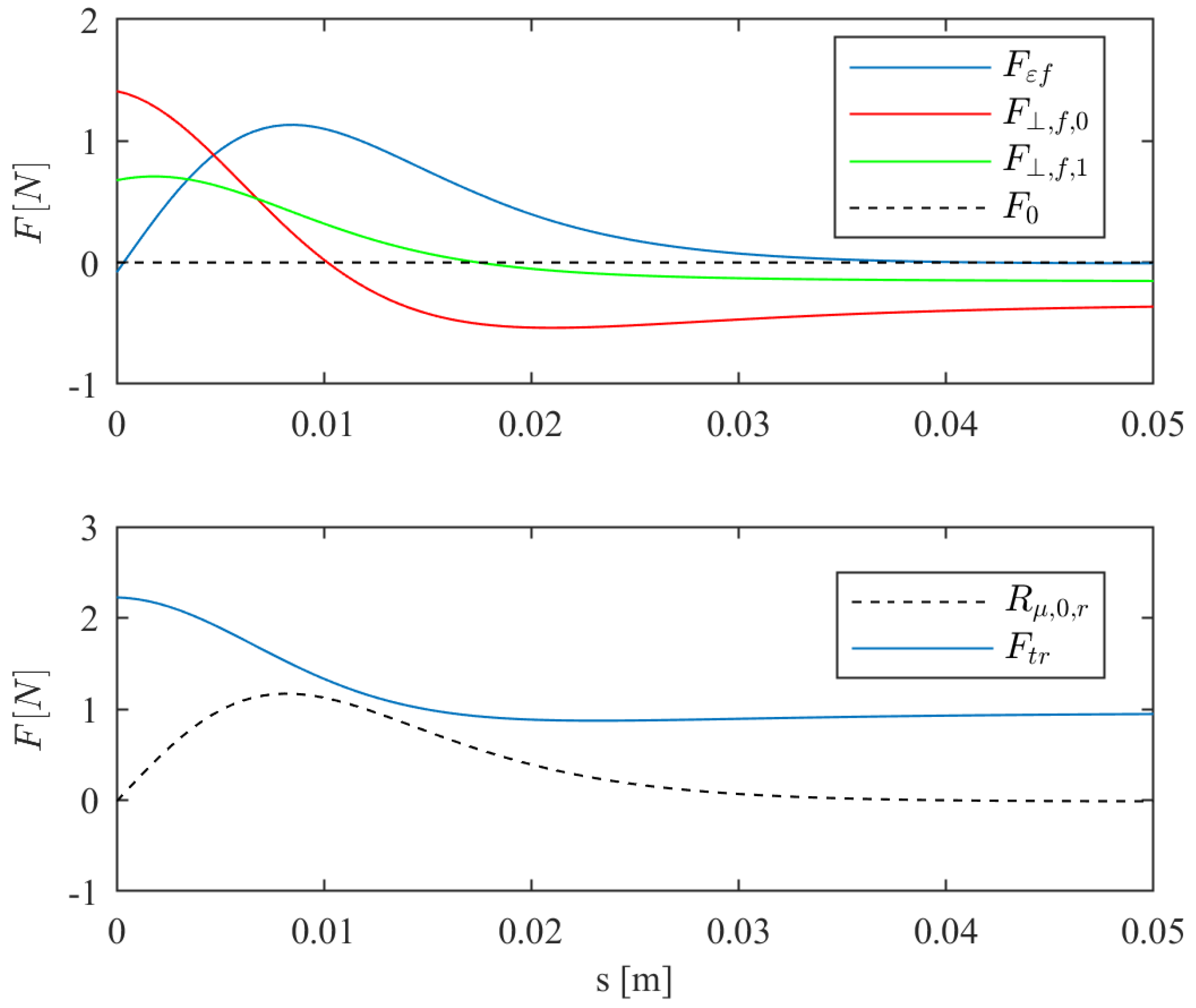
  • magnetic force F m , f acting on the slave robot should be sufficiently high (before contact with the bumper) to allow it to both be pulled along by the master robot and remain attached to the ceiling of the support surface; this is to say, and s : F ε f s < 0 R , 0 , f s > 0 R , 1 , f s > 0 .
The geometry of this case is much the same as that described in Section 3.2. We assume that L = 0 and γ = 0 ; we can also say that t = t p a r k . Therefore, we can conclude that, in this case, parameter s describes the horizontal misalignment between master robot and slave. Furthermore, it happens that R h c = F ε f . In Figure 9, a typical behavior of the main values that satisfies the prerequisites is plotted against coordinate s.

3.5. Traction Margin and Contact Forces

As seen in the previous sections, the master robot experiences a set of forces: magnetic, gravitational, and frictional, and their gross effect determines whether the robot is able to correctly perform. In fact, for the three general conditions expressed in Section 3 to be satisfied, the contact forces need to always be positive and, at the same time, the total tangential force on the master robot should be lower than the traction limit of the wheels. While contact forces R , 0 , r and R , 1 , r are already determined, it can be useful to define an index for the traction limit; we call this the traction margin and indicate it with T μ :
T μ = 1 R μ , 0 , r F t = 1 R μ , 0 , r μ 0 , r R , 0 , r ,
where R μ , 0 , r represents the net tangential force acting on the wheel contact interface as a result of the external forces, and F t = μ 0 , r F , 0 , r is the maximum traction force that can be transmitted through friction, represented by friction coefficient μ 0 , r . Index T μ = 1 , when there is no limit to traction, and T μ 0 , when traction is completely restrained; in this case, slip happens when the wheel turns.
Therefore, in order for Conditions i–iii, described in Section 3 to be satisfied, the following must hold for every equilibrium configuration:
T μ > 0 R , 0 , r > 0 R , 1 , r > 0 .

4. Numerical Implementation and Discussion

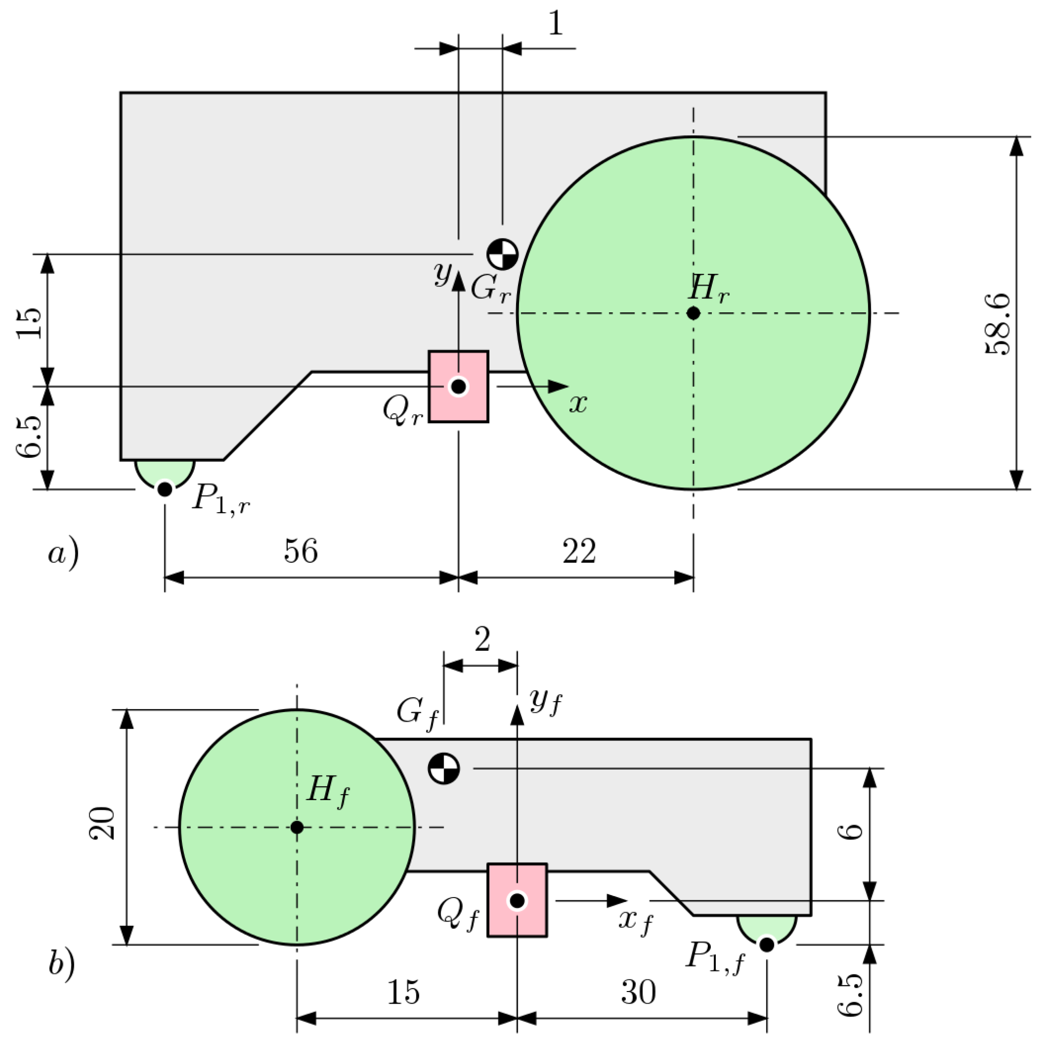
As was stated in Section 3, there are four main phases in the system operation. In order to show the behavior of the robot and to characterize the bounds of its geometrical design parameters, the model was implemented and the results are discussed. The fixed parameters are summarized in Table 1; geometrical parameters are shown in Figure 10. The main condition for operation is expressed in Equation (20).
The sheet that constitutes the main support surface is characterized mainly by its thickness t, curvature radius ρ , and the friction coefficient that emerges when coupled with the wheels and the skid of the master robot and slave. In the following, the results of traction margin T μ are presented in different combinations of parameters, namely, t, the mass of the master robot m m , the orientation of the gravity vector ϑ , and slope angle γ of the parking structure.
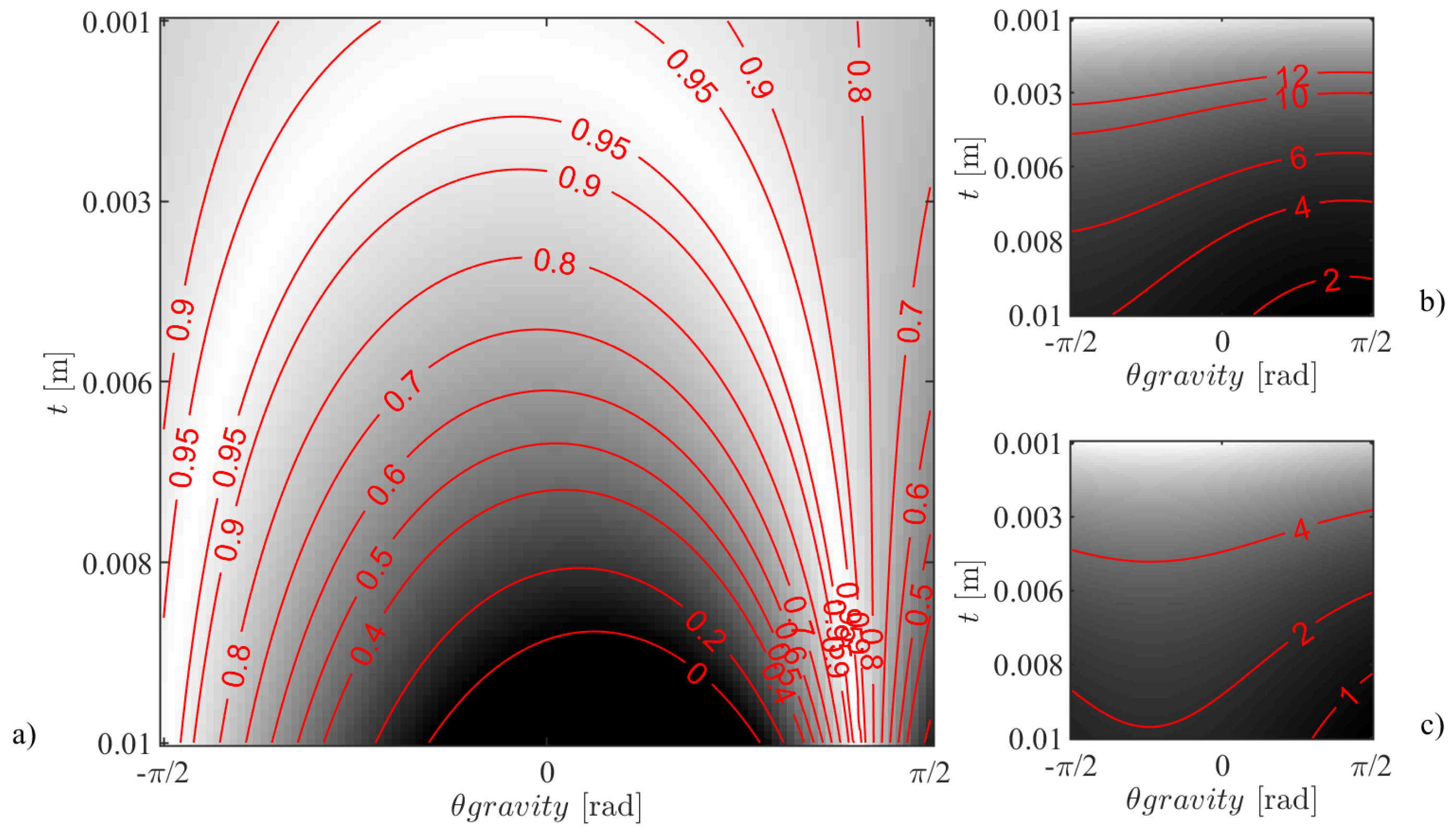
The first aspect that needs to be addressed is the one related to the curved portion of the support sheet. Indeed, as can be seen from Figure 2, the robot travels from an upright to an upside-down configuration by traveling along a cylindrical polycarbonate sheet. The chart in Figure 11 shows how the traction margin behaves for different sheet thicknesses t along the path around the cylinder, represented by gravity vector orientation ϑ . For design purposes, the selection of t can be done by making sure that Equation (20) is satisfied along the entire curved trajectory, i.e., when π / 2 ϑ π / 2 ; this guarantees that the robot operates correctly on the curved sheet.
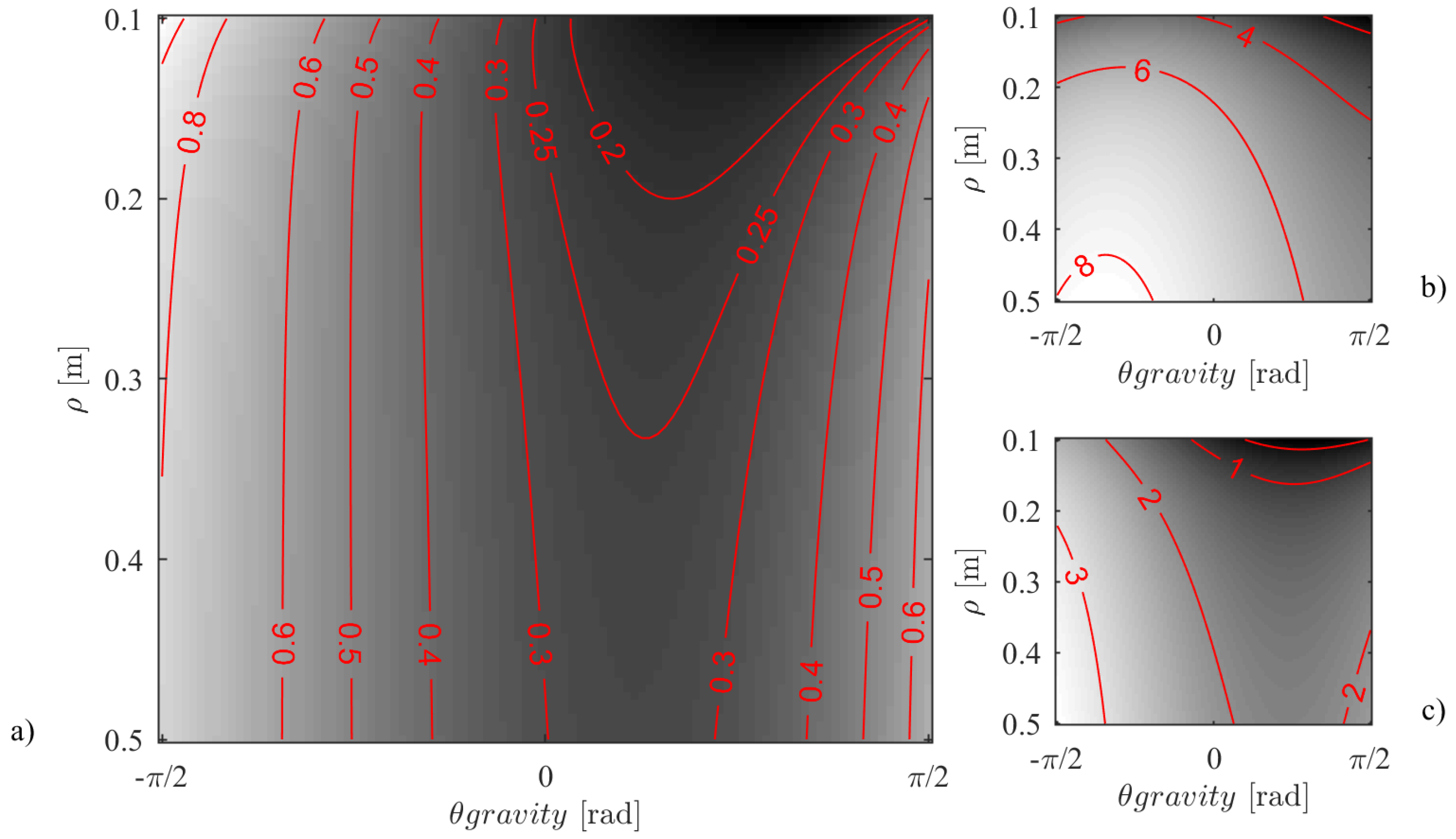
Curvature ρ of the cylindrical surface being the second main parameter, we can see the behavior of T μ against it in Figure 12 along with the contact forces. It is clear from the response surface, that the higher radius ρ is, the more diminished its influence becomes on the traction margin. Assuming that the robot has a larger footprint compared to that of the follower, the effect is explained by noting that, as ρ decreases, the distance between the magnets increases; the obvious consequence is a reduction in magnetic force.
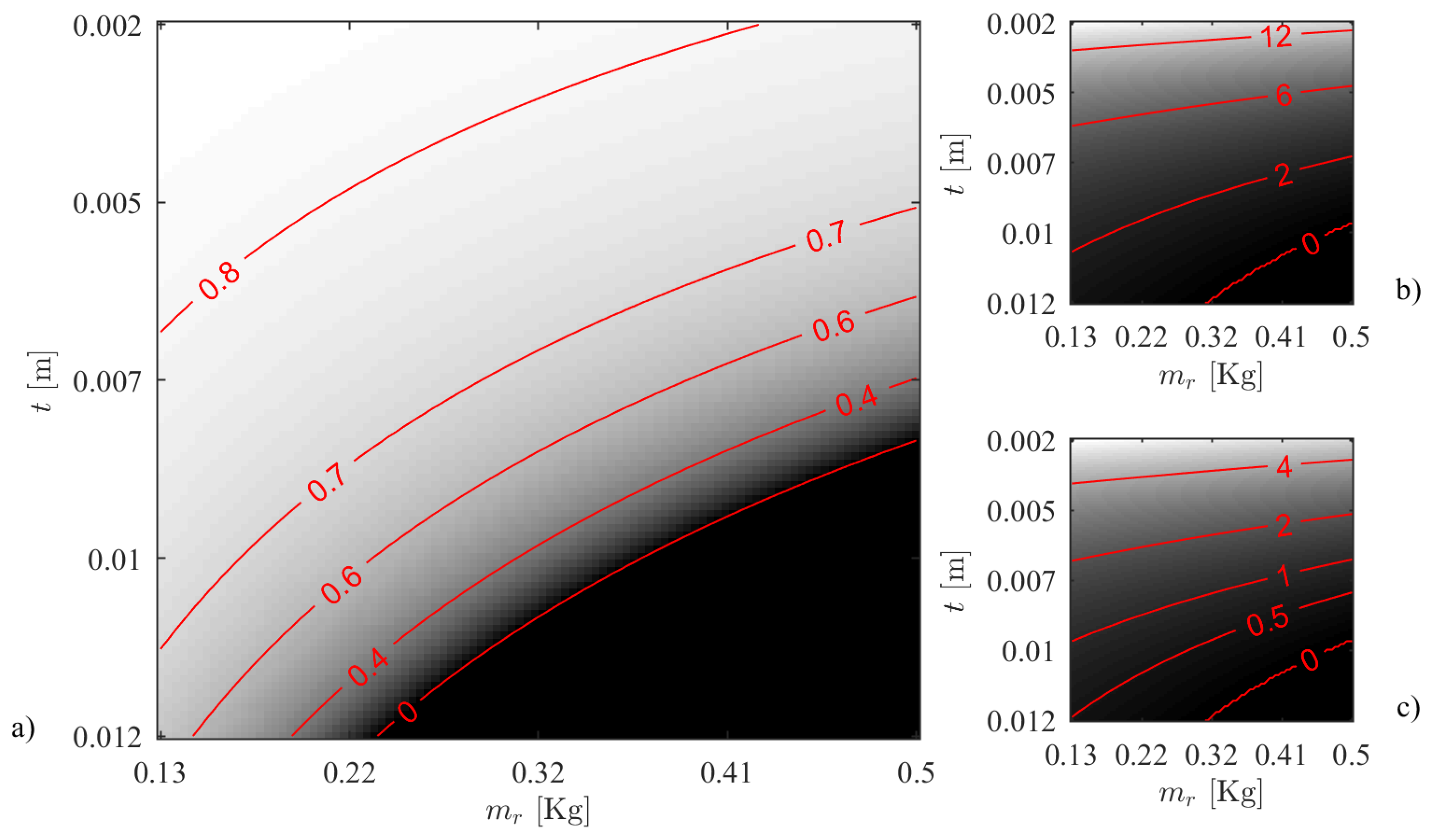
Ceiling operation, i.e., when the robot is overturned, depends on same Conditions (20); however, in this case, the support surface is planar and horizontal: ϑ = π / 2 . It is worth noting that the worst-case scenario is indeed when the surface is horizontal as opposed to otherwise oriented; in Figure 13, the traction margin is shown along with the contact forces: it can be seen that, for a fixed mass of m r = 0.200 kg, contact forces are lower than those existing at ϑ = 0 at the same thickness t, as seen in Figure 11. This observation is made assuming that the influence of curvature is negligible; in fact, as previously discussed, the curvature has a detrimental effect, which strengthens the thesis.
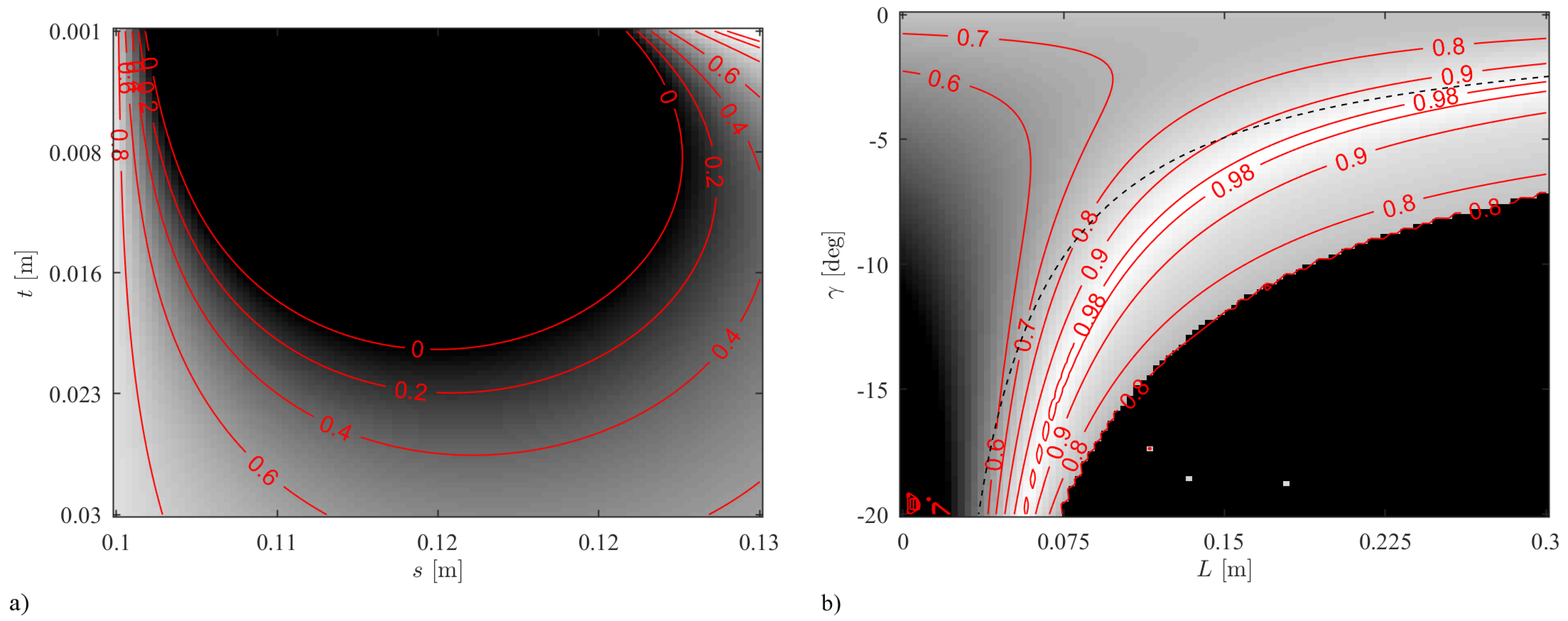
The last fundamental operating scenario is that of parking (Phases D and E). These phases are reversible, i.e., the system can transition F E D C (engaging with the follower cart) similarly to C D E F (parking); note that a certain hysteresis exists that stems from the friction of the follower cart, although this can safely be neglected. Based on the considerations put forth in Section 3.4, in order for coupling/decoupling to work correctly, Conditions i–ii in the same section should be satisfied. As the plot in Figure 14a shows, for small values of sheet thickness t that are otherwise either welcome or even necessary for the correct operation in a climbing phase or in upside-down situations (Figure 11 and Figure 13, respectively), traction margin is null or negative past a certain traveling distance (here shown by misalignment s, which happens because the follower cart is prevented from moving by the bumper in the park area). The direct consequence would be that wheel slip would occur and the robot would not be able to drive away. This effect justifies the ramp structure (Phase E); in Figure 14b, the relation between traction margin, travel length L, and ramp angle γ is shown. It can be seen that lower angles allow a larger traction margin, as expected. Furthermore, once a good candidate for t p a r k has been selected using Figure 14a, a ramp must be designed that reaches said thickness starting from sheet thickness t; to this intent, the dashed line in Plot b can be used. This provides the travel L = ( t p a r k t ) / sin γ required to reach parking thickness, and thus the value up to which the traction margin should be within limits to guarantee a successful operation.

5. Prototype and Experiment Validation

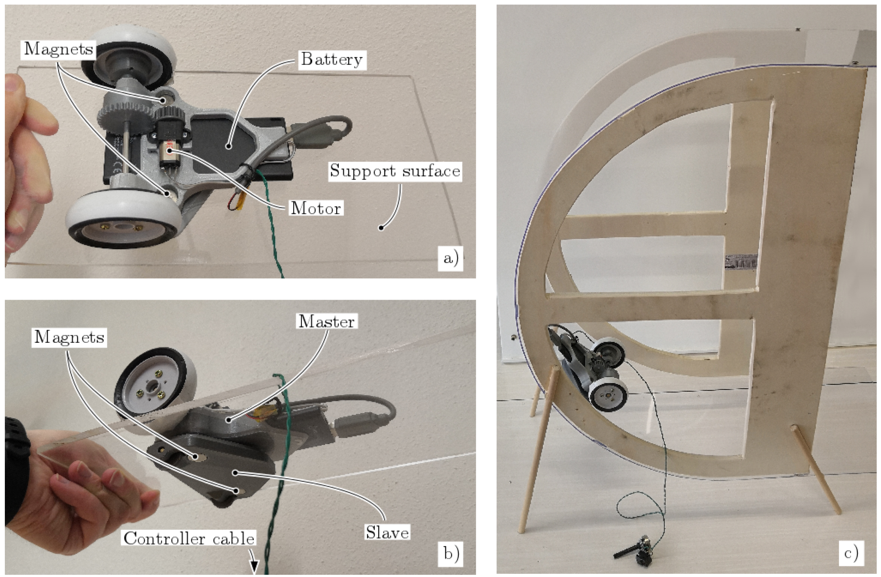
In order to provide an early validation on the model, a functional prototype was built based on the design parameters shown in Table 1. The system is visible in Figure 15. A small 5V DC motor with a 900:1 reduction gearbox was used to drive the wheels forward at varying speed. A 3000 mAh battery was used to provide power on board. Given the simple setup, the robot is capable of driving in the forward direction at speeds between 0 and approximately 0.05 m/s. The maximum torque output of 1.2 Nm (at the wheel) is capable of overcoming friction force F t even at t = 0 , i.e., when magnetic force is at its highest.
Two experiments were defined to provide a comprehensive validation of the model: Experiment 1 was performed to validate the parking phase (Phase E), and Experiment 2 represents motion on a curved surface (Phase B). A comparison with numerical data from the numerical model illustrated in Section 3 is provided. The friction coefficient was lowered artificially from the rubber-PMMA value of μ r , 0 0.90 to a value of μ r , 0 = 0.67 with the addition of a thin layer of white adhesive tape, which can be seen in Figure 15a,b. The rationale for this is to reduce the forces required to induce slip, which has the added benefit of reducing stick-slip events.

5.1. Experiment 1

The experiment consists of the measurement of minimum thickness t of the support sheet that allows the master robot to break free of the slave during the parking phase described in Section 3.4. Indeed, during this phase, the first prerequisite calls for magnetic force F m , r to be sufficiently small for the robot to drive away. This can indeed be seen in Figure 14, and was discussed in Section 4. The same measurement was repeated for several masses of the robot, namely, 0.2, 0.4, 0.6, and 1.2 kg, by adding commensurate additional weights to the robot close to its center of mass G r .
This type of experiment was selected because the mechanics of the parking phase include the most important complex phenomena that influence the behavior of the system, which are
  • friction of the master with respect to the support sheet and
  • magnetic interaction between master and slave.
Being these inherently complex phenomena, described and modeled in detail in Section 3.1, Section 3.2, and Section 3.4, the experimental validation of the parking phase was deemed the most adequate to provide insight on the adherence to reality of the model as a whole.
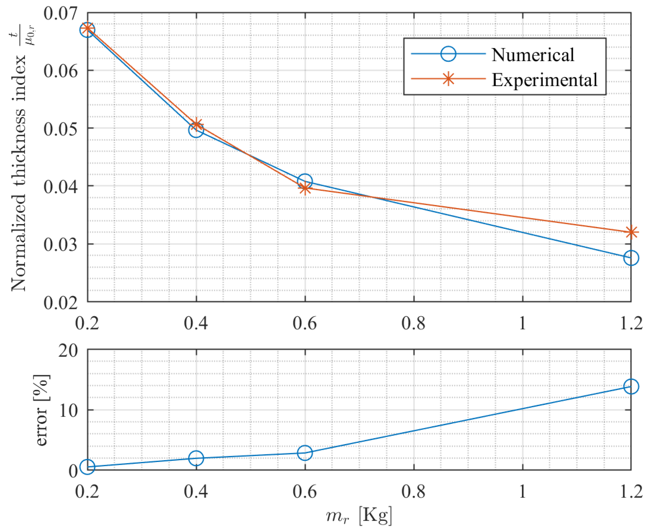
The results of the comparison between the numerical implementation of the model described in Section 3 and the experiment results are shown in Figure 16. It should be noted that a normalized thickness index is used in place of simple thickness value t of the support sheet; normalization allows, in principle, to compare systems with different friction coefficients, although in the present case, normalization is a simple scaling by value 1 / μ 0 , r .
It is apparent from the error plot shown on the bottom of the same figure that the error is comparatively small (from 0.5% to 3%) for large thicknesses and low masses of the master, while it becomes larger (approximately 14%) when thickness grows smaller following larger traction R μ , 0 , r associated with larger masses m r . This is likely due to both the approximate model of the magnetic field that is described in Section 3.1 and the rigid-body approach used for the robot. In fact, large magnetic forces F m arising from small thicknesses t tend to deform the rubber of the wheel, which decreases the distance of the master frame to the support sheet. The direct consequence of this is that the magnetic interaction deviates from its expected behavior. An additional possible source of error can be the model used for the friction; it assumes a linear relationship between force and frictional force. However, during deformation of the rubber due to increased mass m r and magnetic force F m , the footprint of the wheel increases in its area, which can have an unexpected influence on traction R μ , 0 , r and on traction margin T μ .

5.2. Experiment 2

Phase B was experimentally investigated by measuring the maximum travel of the robot from the bottom across the curved portion of the surface, before the wheels lose traction. The angle at which slip occurs, ϑ s l i p , is measured from the horizontal, coherently with the model presented in Section 3: the robot starts at ϑ = π / 2 and travels towards the top of the surface, which is located at ϑ = + π / 2 . Radius ρ of the curved sheet is 0.3 m. The test was performed for a set of four different masses m r of the robot and for a set of four different support-sheet thicknesses t. In particular, m r = [ 0.2 , 0.3 , 0.4 , 0.5 ] kg, while t = [ 0.002 , 0.003 , 0.004 , 0.005 ] m. This provides a total of 16 data points. The raw experimental measurements of ϑ s l i p , which were taken for each data point, varied from 3 to 5.
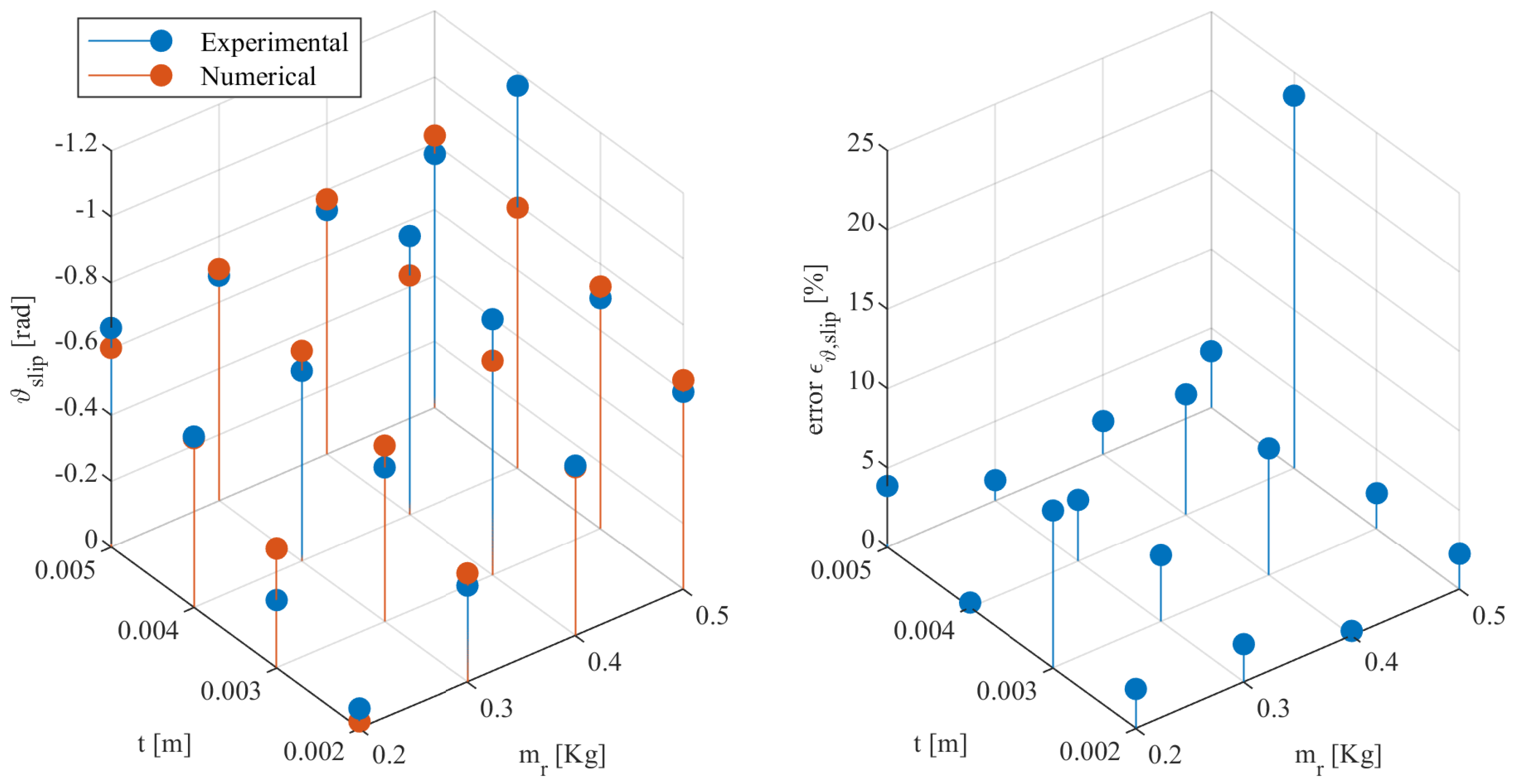
Results shown in Figure 17 show a close similarity in the topology of the surface determined by the variation of parameters m r and t. Results show that the larger the mass, the smaller the angle ϑ s l i p of slip becomes. This means that the robot slips early in its travel along the curved surface. Similarly, the larger thickness t is, the smaller angle ϑ s l i p is. This is expected, because thicker sheets increase the distance of the magnets, which then provide less adhesion force, which clearly translates in less of a traction margin. In order to better measure the error between numerical and experimental results, we define the following:
ε ϑ , s l i p = ( ϑ s l i p , n u m ϑ s l i p , e x p ) π / 2 .
This formulation measures the absolute error and is normalized against π / 2 , which is the travel from the horizontal to the vertical orientation of the robot. The comparison between numerical and experimental data, which is visible in both plots in Figure 17, shows that a comparatively small error is present in the measurements, with an average value of ε ϑ , s l i p = 5 %.
It is worth noting that the system appears nonfunctional in this configuration, although this is caused by the tape on the wheels, which considerably reduces traction. According to the now-validated model and to experimentation, the system is functional without the tape.

6. Conclusions

This paper discussed a type of climbing robot that takes advantage of a master–slave configuration that is connected through a magnetic interface. The master robot provides motion, while the slave component provides adhesion capabilities to the system even when the support sheet is nonmagnetic. Thanks to its design, once decoupled from the slave, the master robot is able to drive freely on horizontal ground.
In order to present a coherent framework, three conditions are defined that prove the feasibility of the specific design. The work envelope of the system is split in a set of phases, namely, driving on straight floor, vertical floor, curved surface, ceiling, and coupling and decoupling phases; each is characterized by its own challenges.
A Taylor expansion model was implemented to model the magnetic-field morphology, and a pseudostatic approach was used to model the master–slave robotic system to account for the inherently nontrivial interaction between the actors.
Comprehensive analysis was performed on the main variables of the master–slave system through numerical computation of the model in the operational envelope. Furthermore, experimental validation was performed both in the case of the parking phase, which is the most complex to model, and in the case of driving along a curved sheet. Both experiments showed that the numerical model had good adherence with reality, with errors around 3%–14% for the parking phase, and 5% for curved-surface driving.
Results clearly show the feasibility of the approach and provide some qualitative and quantitative insight. The experimental validation shows good accuracy of the model compared to reality. The design process of a working prototype can thus be successfully guided via the tools that are provided in the model and its analysis.

Author Contributions

Conceptualization, S.S., P.G.; methodology, S.S.; software, S.S.; validation, S.S.; formal analysis, P.G.; investigation, S.S., L.S.; resources, L.S.; data curating, S.S., L.S.; writing—original-draft preparation, S.S.; writing—review and editing, S.S., L.S., M.C., A.G.; visualization, S.S.; supervision, P.G., A.G.

Funding

This research received no external funding.

Conflicts of Interest

The authors declare no conflict of interest.

References

  1. Cesetti, A.; Scotti, C.; Di Buo, G.; Longhi, S. A service oriented architecture supporting an autonomous mobile robot for industrial applications. In Proceedings of the 18th IEEE Mediterranean Conference on Control and Automation (MED’10), Marrakech, Morocco, 23–25 June 2010; pp. 604–609. [Google Scholar]
  2. Bietresato, M.; Carabin, G.; D’Auria, D.; Gallo, R.; Ristorto, G.; Mazzetto, F.; Vidoni, R.; Gasparetto, A.; Scalera, L. A tracked mobile robotic lab for monitoring the plants volume and health. In Proceedings of the 12th IEEE/ASME International Conference on Mechatronic and Embedded Systems and Applications (MESA), Auckland, New Zealand, 29–31 August 2016. [Google Scholar]
  3. Vidoni, R.; Gallo, R.; Ristorto, G.; Carabin, G.; Mazzetto, F.; Scalera, L.; Gasparetto, A. ByeLab: An agricultural mobile robot prototype for proximal sensing and precision farming. In Proceedings of the ASME 2017 International Mechanical Engineering Congress and Exposition. American Society of Mechanical Engineers, Tampa, FL, USA, 3–9 November 2017. [Google Scholar]
  4. Palacín, J.; Palleja, T.; Valgañón, I.; Pernia, R.; Roca, J. Measuring coverage performances of a floor cleaning mobile robot using a vision system. In Proceedings of the 2005 IEEE International Conference on Robotics and Automation, Barcelona, Spain, 18–22 April 2005; pp. 4236–4241. [Google Scholar]
  5. Quaglia, G.; Bruzzone, L.; Bozzini, G.; Oderio, R.; Razzoli, R.P. Epi. q-TG: Mobile robot for surveillance. Ind. Robot Int. J. 2011, 38, 282–291. [Google Scholar] [CrossRef]
  6. Ristorto, G.; Gallo, R.; Gasparetto, A.; Scalera, L.; Vidoni, R.; Mazzetto, F. A Mobile Laboratory for Orchard Health Status Monitoring in Precision Farming. Chem. Eng. Trans. 2019, 58, 661–666. [Google Scholar]
  7. Carbone, G.; Tedeschi, F.; Gallozzi, A.; Cigola, M. A robotic mobile platform for service tasks in cultural heritage. Int. J. Adv. Robot. Syst. 2015, 12, 88. [Google Scholar] [CrossRef]
  8. Seriani, S.; Gallina, P.; Wedler, A. A modular cable robot for inspection and light manipulation on celestial bodies. Acta Astronaut. 2016, 123, 145–153. [Google Scholar] [CrossRef]
  9. Seriani, S.; Gallina, P.; Wedler, A. Dynamics of a tethered rover on rough terrain. In Advances in Italian Mechanism Science; Springer: New York, NY, USA, 2017; pp. 355–361. [Google Scholar]
  10. Seriani, S.; Scalera, L.; Gasparetto, A.; Gallina, P. Preloaded structures for space exploration vehicles. In Mechanisms and Machine Science; Springer: New York, NY, USA, 2018; pp. 129–137. [Google Scholar]
  11. Silva, M.F.; Machado, J.T.; Tar, J.K. A survey of technologies for climbing robots adhesion to surfaces. In Proceedings of the 2008 IEEE International Conference on Computational Cybernetics, Stara Lesna, Slovakia, 27–29 November 2008; pp. 127–132. [Google Scholar]
  12. Longo, D.; Muscato, G. Design of a single sliding suction cup robot for inspection of non porous vertical wall. In Proceedings of the (ISR 2004) 35th International Symposium on Robotics, Paris-Nord Villepinte, France, 23–26 March 2004. [Google Scholar]
  13. Gao, X.; Kikuchi, K. Study on a kind of wall cleaning robot. In Proceedings of the 2004 IEEE International Conference on Robotics and Biomimetics, Shenyang, China, 22–26 August 2004; pp. 391–394. [Google Scholar]
  14. Yoshida, Y.; Ma, S. Design of a wall-climbing robot with passive suction cups. In Proceedings of the 2010 IEEE International Conference on Robotics and Biomimetics, Tianjin, China, 14–18 December 2010; pp. 1513–1518. [Google Scholar]
  15. Sintov, A.; Avramovich, T.; Shapiro, A. Design and motion planning of an autonomous climbing robot with claws. Robot. Autom. Syst. 2011, 59, 1008–1019. [Google Scholar] [CrossRef]
  16. Balaguer, C.; Gimenez, A.; Jardón, A. Climbing robots’ mobility for inspection and maintenance of 3D complex environments. Autonom. Robot. 2005, 18, 157–169. [Google Scholar] [CrossRef]
  17. Seidl, T.; Vidoni, R. Adhesion to flat surfaces: From spiders to stickers. In Spider Ecophysiology; Springer: New York, NY, USA, 2013; pp. 463–473. [Google Scholar]
  18. Gasparetto, A.; Seidl, T.; Vidoni, R. A mechanical model for the adhesion of spiders to nominally flat surfaces. J. Bionic Eng. 2009, 6, 135–142. [Google Scholar] [CrossRef]
  19. Boscariol, P.; Henrey, M.A.; Li, Y.; Menon, C. Optimal gait for bioinspired climbing robots using dry adhesion: A quasi-static investigation. J. Bionic Eng. 2013, 10, 1–11. [Google Scholar] [CrossRef]
  20. Henrey, M.; Ahmed, A.; Boscariol, P.; Shannon, L.; Menon, C. Abigaille-III: A versatile, bioinspired hexapod for scaling smooth vertical surfaces. J. Bionic Eng. 2014, 11, 1–17. [Google Scholar] [CrossRef]
  21. Cai, J.; He, K.; Fang, H.; Chen, H.; Hu, S.; Zhou, W. The design of permanent-magnetic wheeled wall-climbing robot. In Proceedings of the 2017 IEEE International Conference on Information and Automation (ICIA), Macau, China, 18–20 July 2017; pp. 604–608. [Google Scholar]
  22. Howlader, M.O.F.; Sattar, T.P. Development of magnetic adhesion based climbing robot for non-destructive testing. In Proceedings of the 2015 7th Computer Science and Electronic Engineering Conference (CEEC), Colchester, UK, 24–25 September 2015; pp. 105–110. [Google Scholar]
  23. Howlader, M.O.F.; Sattar, T.P. Design and Optimization of Permanent Magnet Based Adhesion Module for Robots Climbing on Reinforced Concrete Surfaces. In Intelligent Systems and Applications; Springer: New York, NY, USA, 2016; pp. 153–171. [Google Scholar]
  24. Zhang, Y.; Dodd, T.; Atallah, K.; Lyne, I. Design and optimization of magnetic wheel for wall and ceiling climbing robot. In Proceedings of the IEEE International Conference on Mechatronics and Automation, Xi’an, China, 4–7 August 2010; pp. 1393–1398. [Google Scholar]
  25. Ishihara, H. Basic study on wall climbing root with magnetic passive wheels. In Proceedings of the IEEE International Conference on Mechatronics and Automation (ICMA), Takamatsu, Japan, 6–9 August 2017; pp. 1964–1969. [Google Scholar]
  26. Hu, S.; Peng, R.; He, K.; Li, J.; Cai, J.; Zhou, W. Structural design and magnetic force analysis of a new crawler-type permanent magnetic adsorption wall—Climbing. In Proceedings of the 2017 IEEE International Conference on Information and Automation (ICIA), Macau, China, 18–20 July 2017; pp. 598–603. [Google Scholar]
  27. Huang, H.; Li, D.; Xue, Z.; Chen, X.; Liu, S.; Leng, J.; Wei, Y. Design and performance analysis of a tracked wall-climbing robot for ship inspection in shipbuilding. Ocean Eng. 2017, 131, 224–230. [Google Scholar] [CrossRef]
  28. Milella, A.; Maglietta, R.; Caccia, M.; Bruzzone, G. Robotic inspection of ship hull surfaces using a magnetic crawler and a monocular camera. Sens. Rev. 2017, 37, 425–435. [Google Scholar] [CrossRef]
  29. Mao, J.; He, K.; Li, J.; Sun, X. Simulation and experimental verification of permanent magnet adsorption unit for wall-climbing robot. In Proceedings of the 2016 IEEE International Conference on Information and Automation (ICIA), Ningbo, China, 1–3 August 2016; pp. 1189–1194. [Google Scholar]
  30. Tummala, R.L.; Mukherjee, R.; Xi, N.; Aslam, D.; Dulimarta, H.; Xiao, J.; Minor, M.; Dangi, G. Climbing the walls. IEEE Robot. Autom Mag. 2002, 9, 10–19. [Google Scholar] [CrossRef]
  31. Seriani, S.; Scalera, L.; Gasparetto, A.; Gallina, P. A new family of magnetic adhesion based wall-climbing robots. In Proceedings of the 2nd International Conference of IFToMM ITALY, Cassino, Italy, 29–30 November 2018; pp. 223–230. [Google Scholar]
  32. Belforte, G.; Gay, P.; Aimonino, D.R. Robotics for improving quality, safety and productivity in intensive agriculture: Challenges and opportunities. In Industrial Robotics: Programming, Simulation and Applications; IntechOpen: London, UK, 2006. [Google Scholar]
  33. Fiorini, P.; Botturi, D. Introducing service robotics to the pharmaceutical industry. Intell. Serv. Robot. 2008, 1, 267–280. [Google Scholar] [CrossRef]
  34. Griffiths, D.J. Introduction to Electrodynamics, 3rd ed.; Benjamin Cummings: San Francisco, CA, USA, 1998. [Google Scholar]
  35. Landecker, P.B.; Villani, D.D.; Yung, K.W. Analytic solution for the torque between two magnetic dipoles. Magn. Electr. Sep. 1999, 10, 29–33. [Google Scholar] [CrossRef]
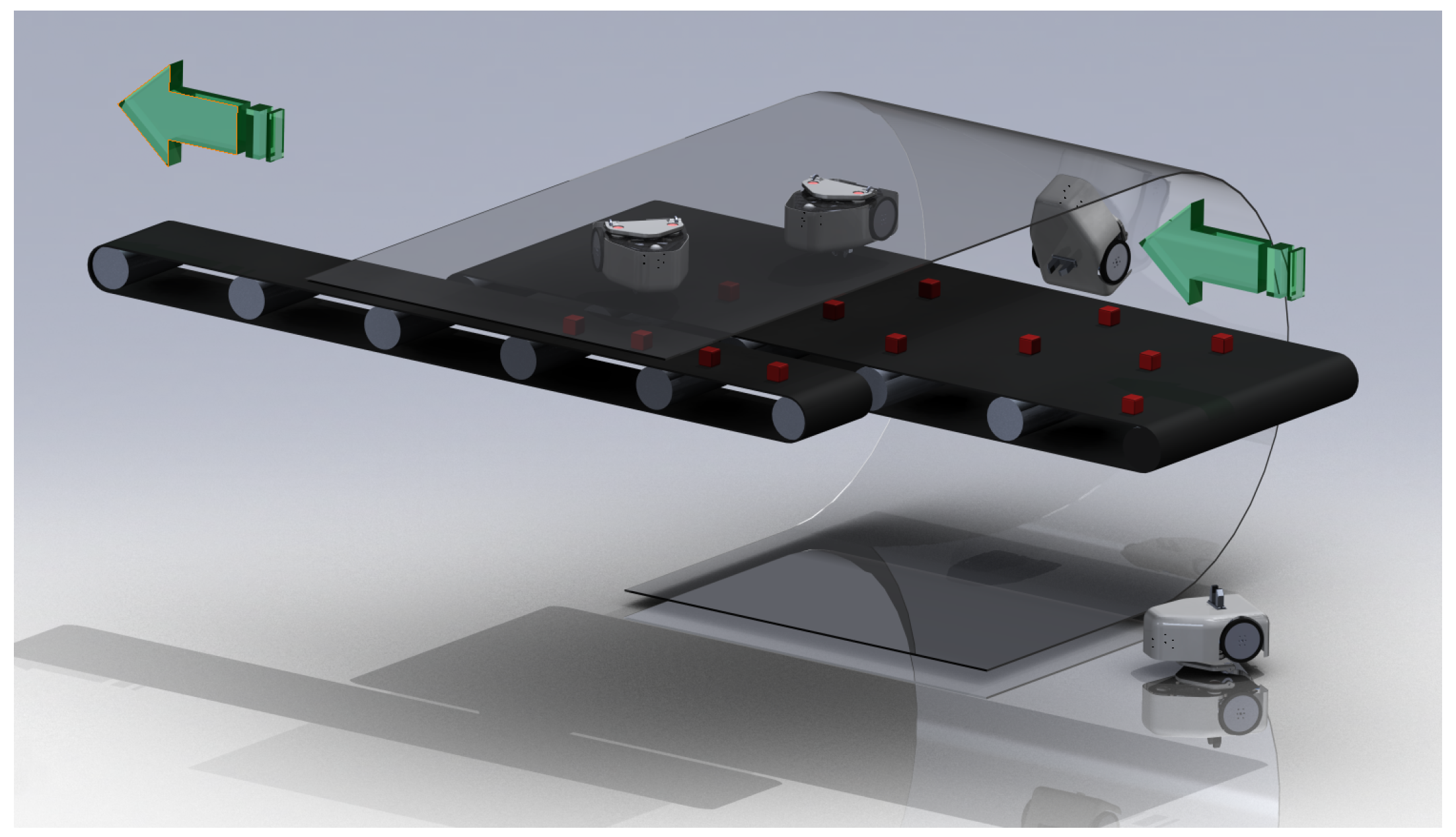
Figure 1. A conceptual illustration of the “upside-down robot” system in a real-world pick-and-place industrial application scenario.
Robotics 08 00041 g001
Figure 2. System description and illustration of different operation phases.
Robotics 08 00041 g002
Figure 3. Morphology of F m field. In the chart, magnetic moments m r and m f are vertically aligned. Moment m r is placed at coordinates ( 0 , 0 ) . Direction of force acting on the second dipole, shown with arrow plot; magnitude of vertical component of the same force, shown in color-coded chart. White area, upward vertical components (i.e., repulsive).
Robotics 08 00041 g003
Figure 4. Straight-surface master–slave interaction. (a) Physical implementation of the actors; (b) geometrical relation between forces and parameter s. Note that friction forces F μ , 0 , f and F μ , 1 , f are represented by a single vector F μ , f for simplicity.
Robotics 08 00041 g004
Figure 5. Behavior of F ε f in relation to master/slave misalignment distance s.
Robotics 08 00041 g005
Figure 6. Master robot and slave on a cylindrical support sheet. (a) Master with respect to axis Ω ; (b) slave in its local frame of reference; (c) whole system in the frame of reference of the master robot.
Robotics 08 00041 g006
Figure 7. Behavior of F ε f in relation to master/slave misalignment angle α .
Robotics 08 00041 g007
Figure 8. Engaging- or parking-phase configuration.
Robotics 08 00041 g008
Figure 9. Development of forces as a function of s during the parking or coupling phase. Dashed line: inferior limit for the curves.
Robotics 08 00041 g009
Figure 10. Geometry and dimensions of the robots. (a) Master and (b) slave.
Robotics 08 00041 g010
Figure 11. Traction margin T μ and contact forces on a curved surface against thickness t and angular position ϑ g r a v i t y along the curved path. (a) Traction margin; contact force for (b) the wheels in P 0 , r and (c) the skid in P 1 , r .
Robotics 08 00041 g011
Figure 12. Traction margin T μ and contact forces on a curved surface against curvature radius ρ and angular position ϑ g r a v i t y along the curved path; (a) Traction margin; contact force for (b) the wheels in P 0 , r and (c) the skid in P 1 , r .
Robotics 08 00041 g012
Figure 13. Traction margin T μ and contact forces during ceiling operation in upside-down condition against mass m r of the robot and thickness t of the support sheet. (a) Traction margin; contact force for (b) wheels in P 0 , r and (c) the skid in P 1 , r .
Robotics 08 00041 g013
Figure 14. Traction margin during parking; (a) T μ during proper parking phase (Phase E) against misalignment s and thickness t; (b) T μ during ramp overcoming (Phase D) against travel L and ramp angle γ ; dashed line: L = L ( t p a r k = 0.020 ) , i.e., the value that L should have to reach t p a r k = 0.020 mm.
Robotics 08 00041 g014
Figure 15. Functional prototype with nonmagnetic transparent support sheet. (a) Top view highlighting position of the master and its main component; (b) bottom view portraying the slave. The controller (a switch-potentiometer setup) is off-screen. (c) Experiment 2 setup, with robot located at approximately ϑ = π / 4 .
Robotics 08 00041 g015
Figure 16. Comparison between numerical and experiment results (Experiment 1). Top plot: data points for different robot masses m r ; below plot: relative error.
Robotics 08 00041 g016
Figure 17. Comparison between numerical results of the model and results from Experiment 2. Left plot: data points for different robot masses m r and for different thicknesses t for both the numerical and experimental campaigns; note that the z-axis is flipped. Right plot: relative error between numerical and experimental values, normalized with respect to π / 2 .
Robotics 08 00041 g017
Table 1. Fixed design parameters.
QuantitySymbolValueUnit
Magnetic permeability η 1.257 × 10 6 N/A 2
Magnetic moment (master) M ( m , r ) 0.9950 Am 2
Magnetic moment (slave) M ( m , f ) 0.9950 Am 2
Mass (master) m r 0.200 kg
Mass (slave) m f 0.045 kg
Frict. coeff. of wheel (master) μ ( 0 , r ) 0.67
Frict. coeff. of skid (master) μ ( 1 , f ) 0.05
Rolling resistance coeff. (slave) μ ( 0 , r ) 0.01
Skid coefficient of friction (slave) μ ( 1 , f ) 0.05