Author Contributions
Conceptualization, M.B. and G.S.; methodology, M.B., G.S., S.T., Y.D.S. and P.R.B.; software, M.B., G.S., S.T., Y.D.S., P.R.B. and S.A.; validation, M.B., G.S., S.T., Y.D.S. and P.R.B., formal analysis, M.B., G.S., S.T., Y.D.S. and P.R.B.; data curation, M.B., G.S., S.T., Y.D.S. and P.R.B.; writing—original draft preparation, M.B., G.S., S.T., Y.D.S. and P.R.B.; writing—review and editing: M.G., A.B. and P.S.; supervision, A.B. and P.S.; funding acquisition, P.S. All authors have read and agreed to the published version of the manuscript.
Appendix A. Comparison of Functionalities
In this appendix, we provide a brief description of some existing libraries and summarize the information in
Table A1.
Thunder_Dynamics: A high-performance C++/Python tool to create C++ libraries with Python bindings. Initially developed for adaptive control, now integrates kinematics, dynamics, and regressor formulations. The user can add symbolic custom functions in CasADi and use them in the generated library.
Pinocchio [7]: A high-performance C++ library with Python bindings, implementing state-of-the-art algorithms based on Featherstone’s recursive Newton–Euler method. Widely used for optimization and real-time control.
Orocos Kinematics and Dynamics Library (KDL): A modular C++ framework designed for real-time robotic applications with strong ROS integration. KDL focuses on kinematic chains and provides a clean, object-oriented interface for forward/inverse kinematics and dynamics computations.
iDynTree [23]: A C++ library with Python bindings specifically designed for free-floating robot dynamics. Originally developed for humanoid robotics, it handles complex multibody systems, including floating-base robots, and provides comprehensive tools for estimation and control.
Robotics Toolbox for Python [28]: A comprehensive Python library providing tools for both serial-link manipulators and mobile robots. It includes over 30 pre-built robot models, trajectory-planning algorithms, and visualization capabilities, making it excellent for education and rapid prototyping.
MATLAB Robotics System Toolbox: A commercial toolbox offering comprehensive support for both manipulator and mobile robot modeling with integrated simulation capabilities. It provides a high-level interface for robot modeling, control design, and simulation within the MATLAB/Simulink environment.
Table A1.
Summary of core features across libraries. “ID” denotes regressors for inertial parameter identification, as defined in (
5). “AD” refers to adaptive-control regressor
as defined in (
6).
Table A1.
Summary of core features across libraries. “ID” denotes regressors for inertial parameter identification, as defined in (
5). “AD” refers to adaptive-control regressor
as defined in (
6).
| Library | Language | Symbolic | Regressors |
|---|
| Thunder_Dynamics (our) | C++/Py | Yes | ID, AD |
| Pinocchio | C++/Py | Partial | ID |
| KDL | C++ | No | No |
| iDynTree | C++/Py | No | ID |
| Robotics Toolbox | Py/MAT | Partial | ID |
| MATLAB Robotics Toolbox | MAT | Partial | No |
Appendix B. Table of Functions
In
Table A2, we report some of the functions implemented in our library, which are available in the generated
Robot class.
Table A2.
Key Functions in Generated Thunder Dynamics Library (N = DoF, P = No. Parameters).
Table A2.
Key Functions in Generated Thunder Dynamics Library (N = DoF, P = No. Parameters).
| Function Name | Description | Output Type/Shape |
|---|
| get_T_0_ee() | End-effector homogeneous transformation | 4 × 4 Matrix |
| get_J_ee() | End-effector geometric Jacobian | 6 × N Matrix |
| get_J_ee_dot() | Time derivative of Jacobian | 6 × N Matrix |
| get_M() | Joint-space mass matrix | N × N Matrix |
| get_C() | Joint-space Coriolis/centrifugal matrix | N × N Matrix |
| get_G() | Joint-space gravity vector | N × 1 Vector |
| get_M_dot() | Time derivative of mass matrix | N × N Matrix |
| get_C_dot() | Time derivative of Coriolis matrix | N × N Matrix |
| get_G_dot() | Time derivative of gravity vector | N × 1 Vector |
| get_Yr() | Dynamics regressor matrix | N × P Matrix |
| get_par_DYN() | Get symbolic dynamic parameters | P × 1 Vector |
| set_par_DYN() | Set symbolic dynamic parameters | (Input: P × 1 Vector) |
| load_conf() | Load parameters from YAML file | (Input: File path) |
Appendix C. Example of Adaptive Control Code
We present an example of the Li–Slotine adaptive controller’s implementation using our framework. This implementation assumes the following variables are available: generalized coordinates q, generalized velocities , desired generalized coordinates , desired generalized velocities , and the initial estimate of the inertial .
auto dq_r = dq_d + LAMBDA ∗ (q_r − q);
auto s = dq_r − dq;
my_robot . setArguments (q, dq, dq_r, ddq_r);
auto Yr = my_robot . get_Yr ();
auto tau = Yr ∗ pi + KD ∗ s;
auto dpi = −Gamma ∗ Yr . transpose () ∗ s;
my_robot . set_par_DYN (pi + dpi ∗ dt);
return tau;
This code snippet represents a full control cycle of the adaptive controller, which includes both the torque control law and the parameter update. The thunder_robot class provides convenient data structures to store the dynamic parameters, allowing them to be accessed in the next control cycles.
Appendix D. Coriolis Matrix Computation Example
To explain the functioning of our approach in
Section 3.3, we apply the algorithm to a simple kinematic chain in an analytical way. For this purpose, we chose a two-DoF elbow robot.
All columns of the regressor are determined by
where
are the link lengths,
for
and
,
, and
Notably, we show how to determine
, step by step. Recalling (
11) leads to
We compute
and its derivative
Now, we use our new algorithm:
Gathering all components, we obtain the final result:
which is analogous to the definition reported at the beginning of this section. For all other matrices, the derivation is straightforward.
Appendix E. Axis-Angle Representation
Given a serial manipulator, the definition of orientation error and its derivatives can be determined in different ways. Our approach exploits the well-known axis-angle representation to define orientation error and orientation velocity error.
We define the frames , , and , as the fixed frame, current end-effector frame, and desired end-effector frame, respectively. We can straightforwardly define R, as the orientation matrices of relative to and relative to , respectively. The orientation matrix of relative to expressed in is defined as . The columns of orientation matrix are defined by orthogonal unit vectors, i.e., , , where .
For a more compact formulation, we recall the definitions of the
skew operator
and the
vect operator
from [
36], i.e.,
. In the following steps, we apply
to vectors and
to antisymmetric matrices. In these cases, the operators act as inverses of each other.
We define the orientation error
as
where
and
are the angle-axis parametrizations of
. As mentioned in [
49],
r and
can be extracted from the matrix
, i.e.,
where
is the element of the matrix
. The computation of
r with this formulation can lead to numerical problems. However,
means that there is no rotation error. In this sense, the concept of an axis becomes arbitrary, and we can solve the numerical problem by setting
r to any unit vector.
The orientation velocity error can be expressed as
where
,
are the current and desired angular velocity of the end-effector, and
Note that
, where
is the orientation part of the geometric Jacobian; we can write (
A3) as follows:
Appendix F. Adaptive Backstepping Stability Proofs
In this section, we report all the proofs about the Adaptive Backstepping stability..
Appendix F.1. Proof of Proposition 1
Proof. Taking the candidate Lyapunov function
with
, a positive-definite and time-invariant matrix, the time derivative is
Given that
is also a symmetric positive-definite matrix by definition,
is negative-definite. As
is positive-definite time-invariant and
is negative-definite, we can infer asymptotic stability from the Lyapunov theorem. □
It is worth noting that the simplification in the computation of is possible only if the Jacobian J is full rank. More precisely, if J is not full rank, is not definite, and no conclusions can be drawn about the asymptotic stability. However, J loses rank only if the manipulator reaches a singular configuration, and this condition being avoided is one of the assumptions made in this work.
Appendix F.2. Proof of Proposition 2
Proof. Take the time-variant Lyapunov candidate
where
is the Lyapunov function used in the proof of kinematics control, i.e., (
A6). Computing the derivative of (
A8) leads to
If matrix
C is written in Christoffel form,
is skew-symmetric and so
is null. At this point, we have
Applying Lyapunov’s theorem to a time-variant system, the system, in terms of variables
, has a time-variant positive-definite candidate,
that is limited by the
function, as shown in [
50], and its derivative
is time-invariant and negative-definite. Therefore, we can deduce the condition of asymptotic stability. □
Appendix F.3. Proof of Proposition 3
Proof. When choosing
as state-space coordinates, a new candidate Lyapunov function can be defined as
where
is the Lyapunov function used in the proof of dynamics control, i.e., (
A8). Computing the derivative, as in (
A10), we have
where, since the real parameters are fixed in time,
. Recalling Equation (
6), the system dynamics are linear in the dynamic parameters, and the control (
33) can be rewritten as follows:
where
is the control action (
32). Substituting (
A13) into (
A12), it becomes
Since exists
that holds
Using Theorem 8.4 from [
51], it holds that
. From this and (
A14),
and
. □
Figure 1.
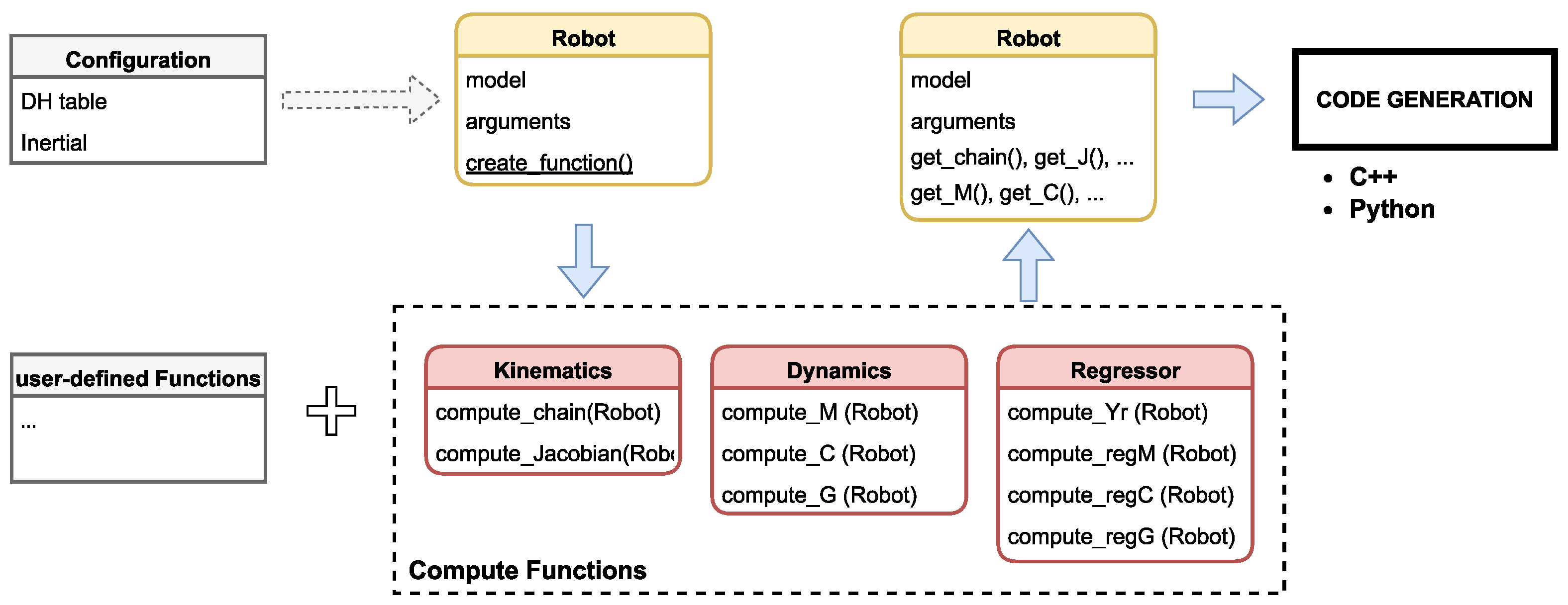
Simplified UML diagram of the framework. The main program takes a configuration file as input, creates the robot, and fills it with functions, both default (kinematics, dynamics) and user-defined. The resulting object is then included in a C++ library.
Figure 1.
Simplified UML diagram of the framework. The main program takes a configuration file as input, creates the robot, and fills it with functions, both default (kinematics, dynamics) and user-defined. The resulting object is then included in a C++ library.
Figure 2.
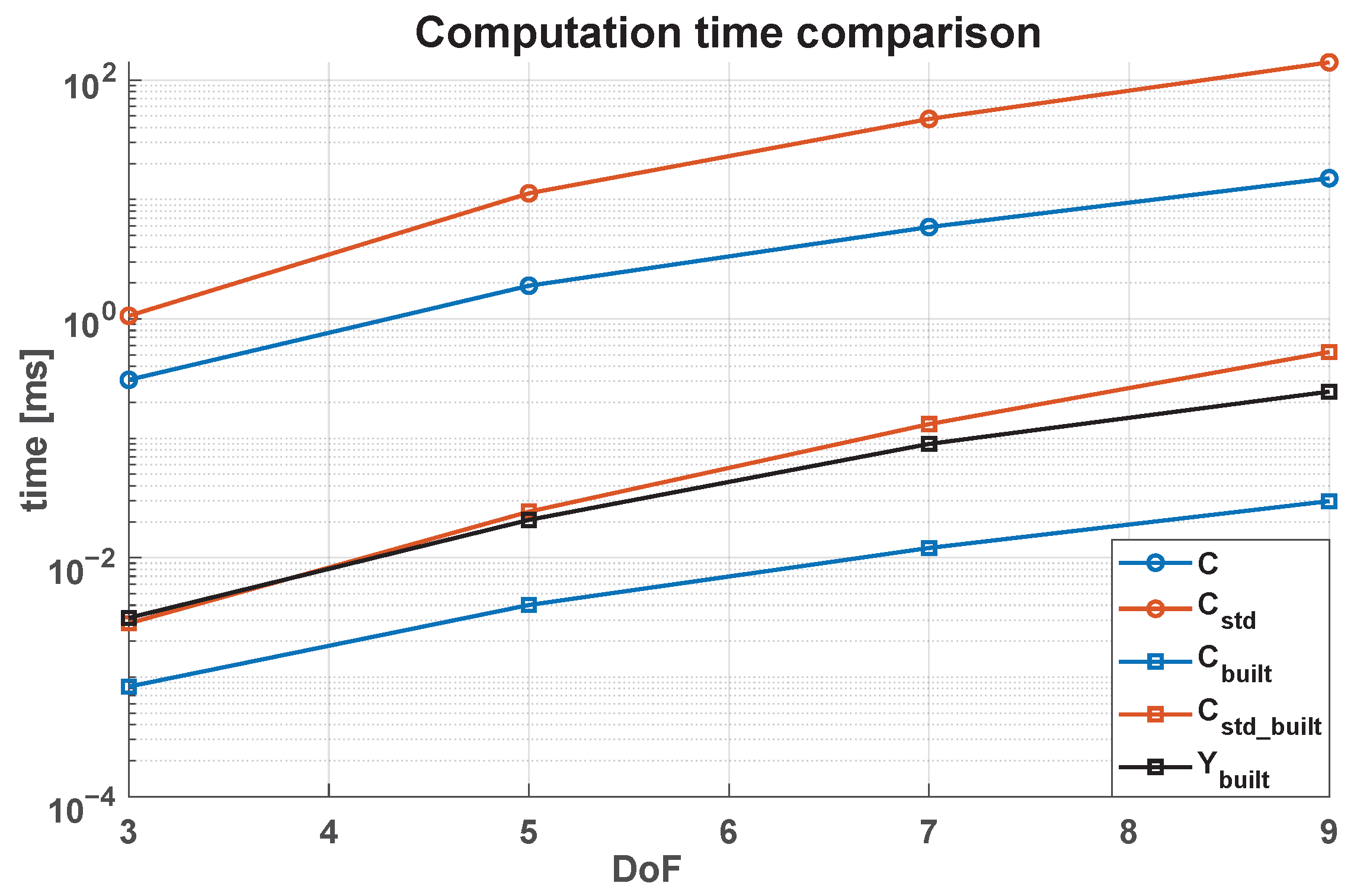
Execution time comparison of different algorithms. Our algorithm is generally faster and permits the real-time adaptive control of a 7-DoF manipulator.
Figure 2.
Execution time comparison of different algorithms. Our algorithm is generally faster and permits the real-time adaptive control of a 7-DoF manipulator.
Figure 3.
Overall scheme of the Adaptive Backstepping Control. The desired Cartesian trajectory serves as the input to the Inverse Kinematics block, which generates new joint references and new coordinates. These outputs are utilized by the Adaptive Law block for updating inertial parameters and by the Control block to ensure asymptotic stability. The Plant block completes the loop. All matrices are obtainable using the Thunder Dynamics Library.
Figure 4.
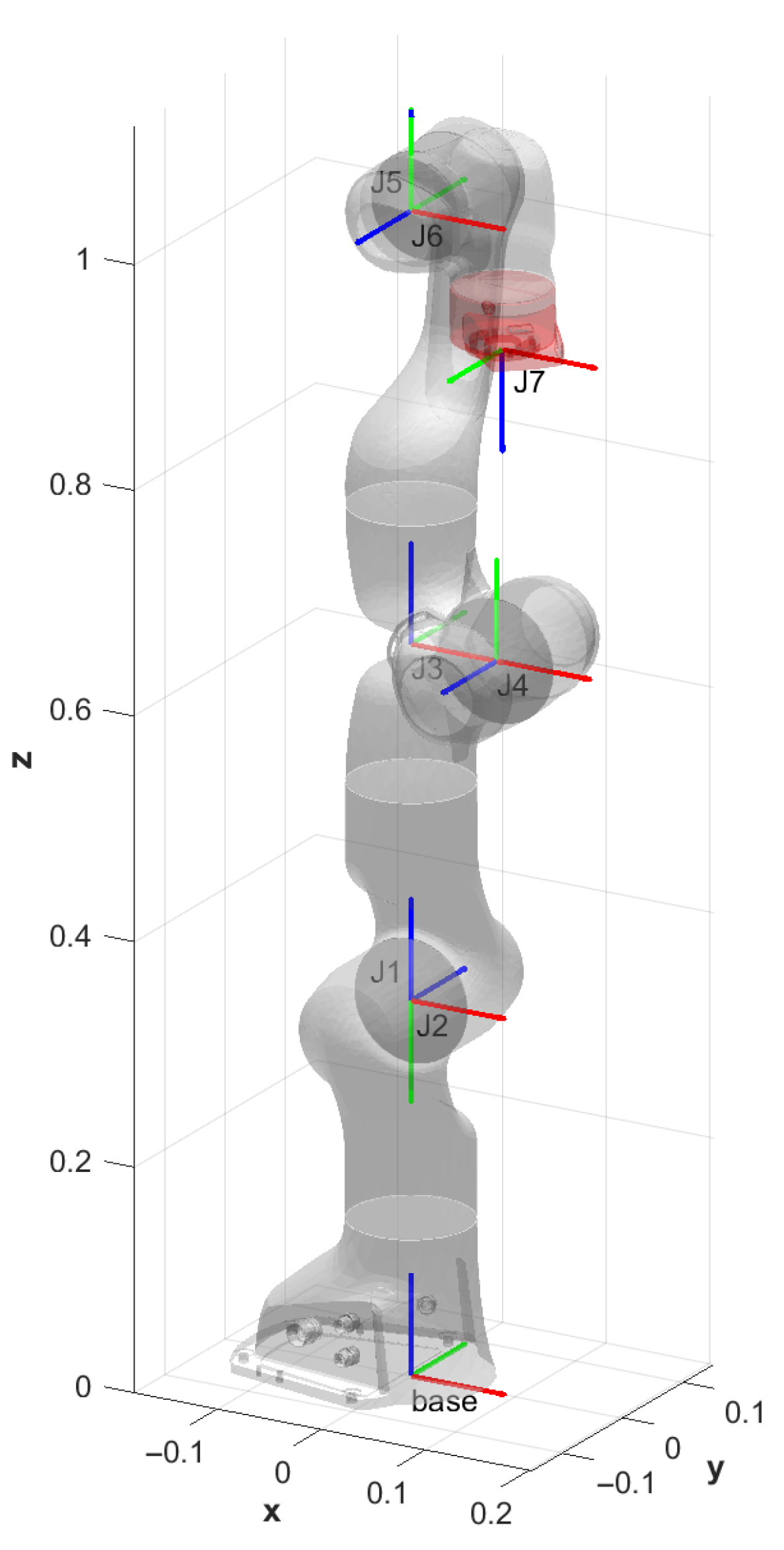
Frames obtained with Denavit–Hartenberg parametrization.
Figure 4.
Frames obtained with Denavit–Hartenberg parametrization.
Figure 5.
Lissajous trajectory used in the experimental validation.
Figure 5.
Lissajous trajectory used in the experimental validation.
Figure 6.
Error norm with respect to (simulation test): (Blue), (Red), (Yellow).
Figure 6.
Error norm with respect to (simulation test): (Blue), (Red), (Yellow).
Figure 7.
Parameters updated with respect to (simulation test): (Blue), (Red), (Yellow).
Figure 7.
Parameters updated with respect to (simulation test): (Blue), (Red), (Yellow).
Figure 8.
Norm-2 of error with respect to (laboratory test): (Yellow), (Red), (Blue).
Figure 8.
Norm-2 of error with respect to (laboratory test): (Yellow), (Red), (Blue).
Figure 9.
Parameter updates with respect to (laboratory test): (Yellow), (Red), (Blue).
Figure 9.
Parameter updates with respect to (laboratory test): (Yellow), (Red), (Blue).
Figure 10.
Norm-2 of error (laboratory test): no-adaptive controller (Red), adaptive controller (Blue).
Figure 10.
Norm-2 of error (laboratory test): no-adaptive controller (Red), adaptive controller (Blue).
Figure 11.
Franka Emika Panda with Softhand.
Figure 11.
Franka Emika Panda with Softhand.
Figure 12.
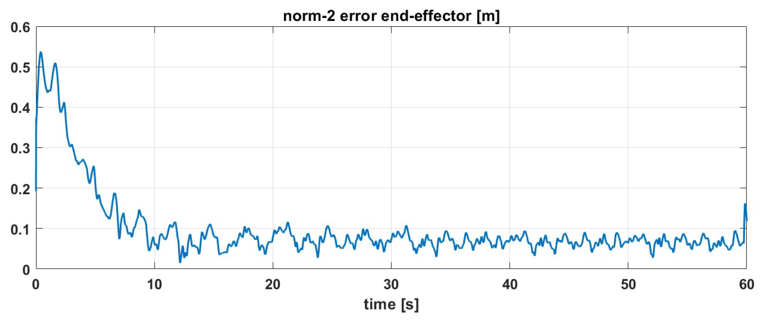
Norm-2 of error with Softhand on a 3D Lissajous trajectory.
Figure 12.
Norm-2 of error with Softhand on a 3D Lissajous trajectory.
Figure 13.
Parameter updates with Softhand on a 3D Lissajous trajectory.
Figure 13.
Parameter updates with Softhand on a 3D Lissajous trajectory.
Table 1.
Notation.
| element in i-th row and j-th column of matrix A. |
| element in i-th position of vector v. |
| i-th row of matrix A. |
| j-th column of matrix A. |
| derivative of matrix A with respect to v. |
| reorganize the elements of the matrix/vector in p rows and in q columns. |
Table 2.
Time comparison for the robot and library creation.
Table 2.
Time comparison for the robot and library creation.
| DoF | 3 | 5 | 7 | 9 | 15 | 30 |
|---|
| Robot creation [] | 23 | 81 | 326 | 954 | 5582 | 18,454 |
| Library creation [] | | | | | | |
Table 3.
Execution time statistics. The lowest values of computation time for each quantity are written in bold.
Table 3.
Execution time statistics. The lowest values of computation time for each quantity are written in bold.
| Library | J | | M | C | |
Y
|
|---|
| Our [] | 101 | 149 | 534 | 6003 | 1607 | 32,279 |
| Our () | 21.3 | 7.6 | 22.1 | 697 | 74.0 | 1834 |
| Our (CV [%]) | 21.2 | 4.4 | 4.2 | 12.0 | 4.6 | 6.1 |
| Pinocchio [] | 402 | 908 | 969 | 3444 | 5774 | 5197 |
Table 4.
Overall control law.
Table 4.
Overall control law.
| Variable | Definition | Reference |
|---|
| e | | (27) |
| | (30) |
| s | | (31) |
| | (33) |
| | (34) |
Table 5.
Denavit-Hartenberg Table.
Table 5.
Denavit-Hartenberg Table.
| Linki | | | | |
|---|
| 1 | 0 | 0 | 0.3330 | |
| 2 | 0 | − | 0 | |
| 3 | 0 | | 0.3160 | |
| 4 | 0.0825 | | 0 | |
| 5 | −0.0825 | − | 0.384 | |
| 6 | 0 | | 0 | |
| 7 | 0.088 | | 0.107 | |
Table 6.
Steady-state and rise time values of tracking errors for different values of .
Table 6.
Steady-state and rise time values of tracking errors for different values of .
| | Kd1 | Kd2 | Kd3 |
|---|
| Steady-state error | 0.0258 | 0.0219 | 0.0226 |
| Rise time [] | 15.102 | 19.612 | 15.961 |
Table 7.
Steady-state and rise time values of tracking error for different values of .
Table 7.
Steady-state and rise time values of tracking error for different values of .
| | | | |
|---|
| Steady-state error | 0.0136 | 0.0219 | 0.1204 |
| Rise time [] | 3.668 | 19.612 | 23.572 |
Table 8.
Estimation of Softhand + Link 7 parameters in .
Table 8.
Estimation of Softhand + Link 7 parameters in .
| | Mass [kg] | CoMx [m] | CoMy [m] | CoMz [m] |
|---|
| True | 1.5655 | 0.06170 | −0.0004 | 0.0009 |
| Estimate | 1.7542 | 0.0414 | −0.0039 | −0.0191 |
| Initial | 0.736 | 0.014 | −0.004 | −0.045 |


