Article

Untethered Origami Worm Robot with Diverse Multi-Leg Attachments and Responsive Motions under Magnetic Actuation

by
Manivannan Sivaperuman Kalairaj
1,
Catherine Jiayi Cai
1,2,
Pavitra S
1 and
Hongliang Ren
1,3,4,*
1
Department of Biomedical Engineering, National University of Singapore, Singapore 117575, Singapore
2
Singapore Institute of Manufacturing Technology, A*STAR Singapore, Fusionopolis Two, 4 Fusionopolis Way, Singapore 138635, Singapore
3
Department of Electronic Engineering, The Chinese University of Hong Kong, Hong Kong, China
4
Shun Hing Institute of Advanced Engineering, The Chinese University of Hong Kong, Hong Kong, China
*
Author to whom correspondence should be addressed.
Robotics 2021, 10(4), 118; https://doi.org/10.3390/robotics10040118
Submission received: 2 August 2021 / Revised: 27 October 2021 / Accepted: 27 October 2021 / Published: 1 November 2021
(This article belongs to the Special Issue Robotics: 10th Anniversary Feature Papers)

Abstract

:
Nowadays, origami folding in combination with actuation mechanisms can offer deployable structure design, yield compliance, and have several properties of soft material. An easy complex folding pattern can yield an array of functionalities in actuated hinges or active spring elements. This paper presents various cylinder origami robot designs that can be untethered magnetically actuated. The different designs are analyzed and compared to achieve the following three types of motion: Peristaltic, rolling, and turning in different environments, namely, board, sandpaper, and sand. The proposed origami robot is able translate 53 mm in peristaltic motion within 20 s and is able to roll one complete cycle in 1 s and can turn ≈180 in 1.5 s. The robot also demonstrated a peristaltic locomotion at a speed of ≈2.5 mm s 1 , ≈1.9 mm s 1 , and ≈1.3 mm s 1 in board, sandpaper, and sand respectively; rolling motion at a speed of 1 cycle s 1 , ≈0.66 cycles s 1 , and ≈0.33 cycles s 1 in board, sandpaper, and sand respectively; and turning motion of ≈180 , ≈83 , and ≈58 in board, sandpaper, and sand respectively. The evaluation of the robotic motion and actuation is discussed in detail in this paper.

1. Introduction

Origami-like folding [1,2,3] of papers widely have lightweight and low-cost structures with stiffness and flexibility simultaneously. The origami pattern used to fabricate the structure dominates the mechanical properties of the entire structure [4]. The origami folded structures used in this application are hollow or a shell, making it lightweight and flexible, and the folding pattern improves the structure’s stiffness. Alternating the crease patterns of the origami structures can be used to tune the mechanical behavior of the structure [4,5]. Origami-folded cylinders [6,7] are used for deployable structures in space [8], safety features in automobiles such as airbags [9], and in medical applications such as stents [10] where reduction and expansion of the structure are desirable due to the narrow navigation spaces. The shape and size transformation of the passive origami-folded structures opens a wide range of applications when a suitable actuation method is utilized.
Appropriate actuation mechanisms include tendon-driven [11], pneumatic [12], piezoelectric [13], magnetic [14], or shape memory alloys [15,16,17,18,19]. Tethered actuation mechanisms such as tendon-driven mechanism could be difficult to control when navigating through narrow complex pathways. Using tendon-driven mechanism to achieve peristaltic motion in origami robot demonstrated difficulties in achieving sharp turns to navigate through narrow pathways [1]. The possibility of leaking [4] in pneumatic actuation and the inability to detect it immediately reduces the actuation performance and makes it unsuitable for long-distance locomotion. Piezoelectric materials have limited strain and are brittle, making them ineffective for origami structures involving high strains. Although strain could be amplified [13] using advanced MEMS techniques, the cost of fabrication increases. Shape memory actuation is generally of a low frequency due to its slow response time and limited heat-dissipation capabilities [16,17,18,19], restricting its use in applications requiring faster locomotions of the robot. Magnetic fields have a relatively fast response time (0–0.1 s) [20,21], rendering it to be a more suitable actuation mechanism for this application. Either permanent magnets or electromagnets can generate magnetic fields. Electromagnetic systems are capable of exceptional remote control with external magnetic field generators, but utilizing them for small-scale applications by scaling down electromagnetics is insignificant due to high power consumption [22]. Typically, a large size and bulky setup are required by the electromagnetic field to operate successfully. On the other hand, external permanent magnets can be controlled easily. They can be scaled up or down to the required application easily, making it an appropriate actuation method for the origami-based robot.
Herein, we demonstrate an origami-based soft robot with different configurations of iron (paramagnetic) sheets actuated using a permanent magnet (ferromagnetic) to generate three different locomotions (peristaltic, rolling, and turning) in three different environments (board, sandpaper, and sand). We observed the displacement and velocity changes in the proposed designs and their impact on different environments during actuation using an external permanent magnet. Furthermore, we discuss methods to improve this design to facilitate the robot in biomedical applications such as endoscopy and colonoscopy.

2. Materials and Methods

The soft robot consists of a paper-based backbone with iron sheets (paramagnetic) attached. Different configurations of the iron sheets were assembled and their influences in locomotions were tested by actuating with a permanent magnet (ferromagnetic). The steps involved in the fabrication of the backbone of the soft robot are shown in Figure 1a and the three different configurations of iron sheets placements are shown in Figure 1b–d.

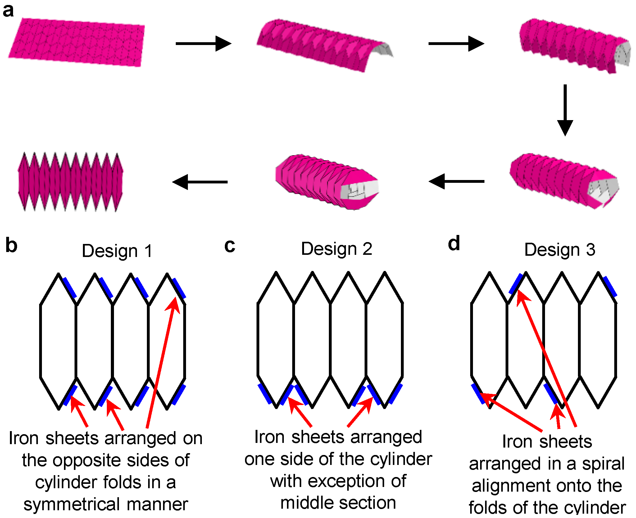
2.1. Fabrication of Soft Robot

The soft robot was fabricated using a popular origami-folded cylinder design inspired by the Miura design [15,23]. The Miura design allows expansion and compression in the horizontal direction without changing the vertical direction. This expansion and contraction motion mimics a peristaltic movement observed in earthworms. One of the Miura derivatives is the Arc-Miura pattern, which looks similar to the Miura pattern, altering the mountain and valley vertices. These vertices determine the consequent mountain and valley fold patterns that arise from these zig-zag crease patterns and are the foundation of the Arc-Miura cylinder design. The Arc-Miura pattern of an origami-folded cylinder does not have any curvature limitations [24], thus enabling the bending of the soft robot. The folded structure was an octagonal cylinder with a diameter of 15 mm and a fully contracted and expanded length of 20 mm and 50 mm respectively but the working range of the robot varies between ≈30 mm and ≈40 mm. The small diameter of the soft robot was selected to facilitate its motion in narrow spaces such as the GI tract or oral cavity for surveillance purposes. The crease lines for the Arc-Miura pattern were defined by embossing using Silhouette Curio™ on a 80 g m 2 paper and folded to an origami-folded cylinder as per the steps shown in Figure 1a. The design embossed in the paper consists of multiple squares of equal dimensions of 5 mm × 5 mm. The open edges of the cylinder were closed using PVA adhesive, forming the passive backbone of the soft robot.

2.2. Configuration of Iron Sheets in the Soft Robot

Paramagnetic material was coated to the origami-folded cylinder as an active component in the robot. Iron sheets from Titan™ Magnetics were used as the paramagnetic material for assembly in the robot. Iron sheets of size 3 mm × 4 mm and a thickness of 0.7 mm were then attached to squares of 5 mm × 5 mm on the folds of the origami-folded cylinder using UHU® adhesive. A number of iron sheets of the specified dimensions were arranged on the mountain folds of the paper backbone in three different configurations (design 1, design 2, and design 3). In design 1, the iron sheets were arranged on opposite sides of the folds in the symmetrically-folded cylinder, as shown in Figure 1b. In design 2, the iron sheets were arranged only on one side of the origami-folded cylinder except for the middle section, as shown in Figure 1c. In design 3, the iron sheets were arranged in a spiral alignment onto the folds of the origami-folded cylinder, as shown in Figure 1d. The three different configurations of the iron sheet arrangement allow different locomotion of the robot when actuated using a permanent magnet. Due to the paramagnetic nature of the iron sheets, changing the orientation (north pole or south pole) of the permanent magnet will have no change in the motion of the robot.

2.3. Actuating Magnet

A neodymium-iron-boron (NdFeB) alloy cube (20 mm × 20 mm × 20 mm) permanent magnet (ferromagnetic) from Titan™ Magnetics was used for actuating the soft robot. Changing the orientation of the permanent magnet does not have any effect on the iron sheet due to its paramagnetic nature. The soft robot was placed on a thin flat surface (thickness, ≈1 mm), and the permanent magnet (actuating or driving magnet) was moved in different paths to achieve different robotic motions.

3. Results and Discussions

The robot was actuated at three different pathways of the permanent magnet, and the corresponding locomotion (peristaltic, rolling, and turning) were compared for the three different configurations (design 1, design 2, and design 3) of the robot. The video of the actuation path and the locomotion of the robot were recorded and analyzed using Tracker 5.1.4 (Douglas Brown©). All three different motions were compared to different configurations in three different environments (board, sandpaper, and sand). The relative friction co-efficient of the three environments was observed. The corrugated board had the lowest co-efficient, and sand had the highest coefficient of friction, with sandpaper having the intermediate value. Initially, the actuating magnet was placed 50 mm away from the board and then brought closer to actuate the robot.

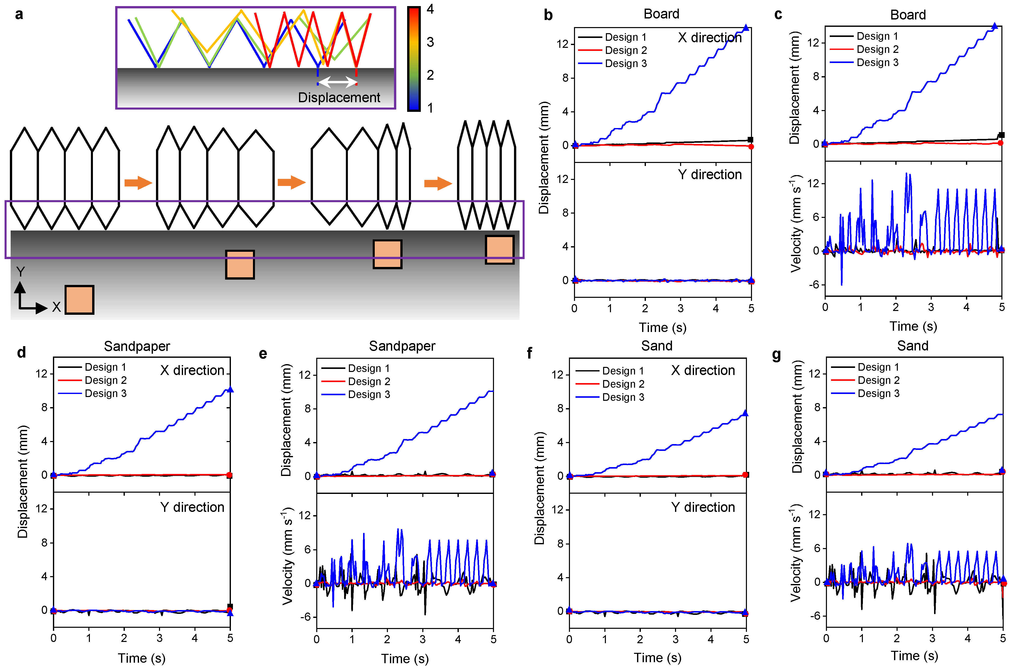
3.1. Peristaltic Motion

The robot demonstrates its ability to translate in a peristaltic motion with continuous contraction and expansion during a specific motion of the actuation magnet. This actuation mechanism of the robot is shown schematically in Figure 2a and the motion of the actuation magnet is shown in its X and Y position in Figure 2b. Initially, the actuating magnet is placed 50 mm away from the board and then raised ≈50 mm and displaced 5 mm along X-direction in ≈4 s. The actuating magnet is then dropped back to ≈50 mm with no changes in X-direction, completing one cycle. This cycle is then repeated for 20 s, and the corresponding robotic locomotion is recorded. The maximum displacement of the robot is observed when the actuating magnet is closest to the board. When the actuating magnet is closest to the board along the Y-direction and 5 mm along the X-direction, the expansion phase occurs, where the front end of the robot extends (body length = ≈ 45 mm) further in the forward direction (towards the actuating magnet) with a maximum displacement of 5 mm depending on the friction between the robot and surface. During the contraction phase, the rear end of the robot is moved towards the front end of the robot, thereby contracting its body (body length = ≈ 30 mm). Once the actuating magnet is moved away from the board, the rear end of the robot starts to relax and returns to its original state (body length = ≈ 40 mm).
Amongst the three configurations, design 3 shows the best peristaltic motion. The sequential pictures of the actuation of design 3 on board, sandpaper, and sand are shown in Figure 3a–c, respectively. The design 3 had the highest displacement and velocity in the board and the lowest in the sand. Thus, the peristaltic motion of design 3 on the surface with a lesser friction coefficient is faster than the surfaces with a higher coefficient of friction. The displacements of the three configurations of the origami-folded robot are obtained in its X and Y direction during actuation as per Figure 2b. The displacement along X and Y directions of the three configurations of the robot on board, sandpaper, and sand are shown in Figure 3a–c. No displacement was observed in the Y-direction for all the configurations in all environments (board, sandpaper, and sand). Peristaltic occurs on the surface smoothly without any vertical bending or lifting of the robot, and hence, there is no displacement along the Y-direction. Design 2 almost had negligible displacement along the X-direction (Figure 3d,f,h) too in all environments (board, sandpaper, and sand). During the cyclic actuation of the permanent magnet, dragging of the robot was observed in design 1 in the board, displaying a displacement of ≈6 mm in 20 s in the X-direction (Figure 3d). Almost negligible displacement was observed along the X-direction when design 1 is actuated in both sandpaper and sand (Figure 3f,g). Design 3 demonstrates a total displacement of ≈53 mm in 20 s along the X-direction when actuated on board (Figure 3d), ≈37 mm in 20 s on sandpaper (Figure 3f), and ≈28 mm in 20 s on sand (Figure 3h). Due to the cyclic actuation of the permanent magnet and the cyclic contraction and expansion of the robot (design 3), a step-shaped displacement is observed in all environments.
The overall displacement and velocity of the three configurations during peristaltic motion on board, sandpaper, and sand are shown in Figure 3e,g,i respectively. Design 2 shows negligible overall displacement (Figure 3e,g,i) in all environments (board, sandpaper, and sand), and Design 1 shows negligible overall displacement on sandpaper and sand (Figure 3f,g). Whereas, an overall displacement of ≈6 mm in 20 s is observed in Design 1 when actuated cyclically (Figure 3d). Design 3 shows an overall displacement of ≈53 mm in 20 s on board (Figure 3d), ≈37 mm in 20 s on sandpaper (Figure 3f), and ≈28 mm in 20 s on sand (Figure 3h).
The actuation of an individual segment (total number of individual segments is 10) of the robot was analyzed to observe the actuation mechanism more precisely. The actuation mechanism of the leg of the robot during peristaltic motion is shown schematically in Figure 4a. Design 3 shows an overall displacement of ≈10 mm in 5 s on board (Figure 4c), ≈7.2 mm in 5 s on sandpaper (Figure 4e), and ≈5 mm in 5 s on sand (Figure 4g). The displacement of the single leg of the robot in X and Y directions during actuation in different environments (board, sandpaper, and sand) are shown in Figure 4b,d,f. When three samples were tested under the same experimental conditions for the peristaltic motion, an error of less than 5 mm was observed in different environments.

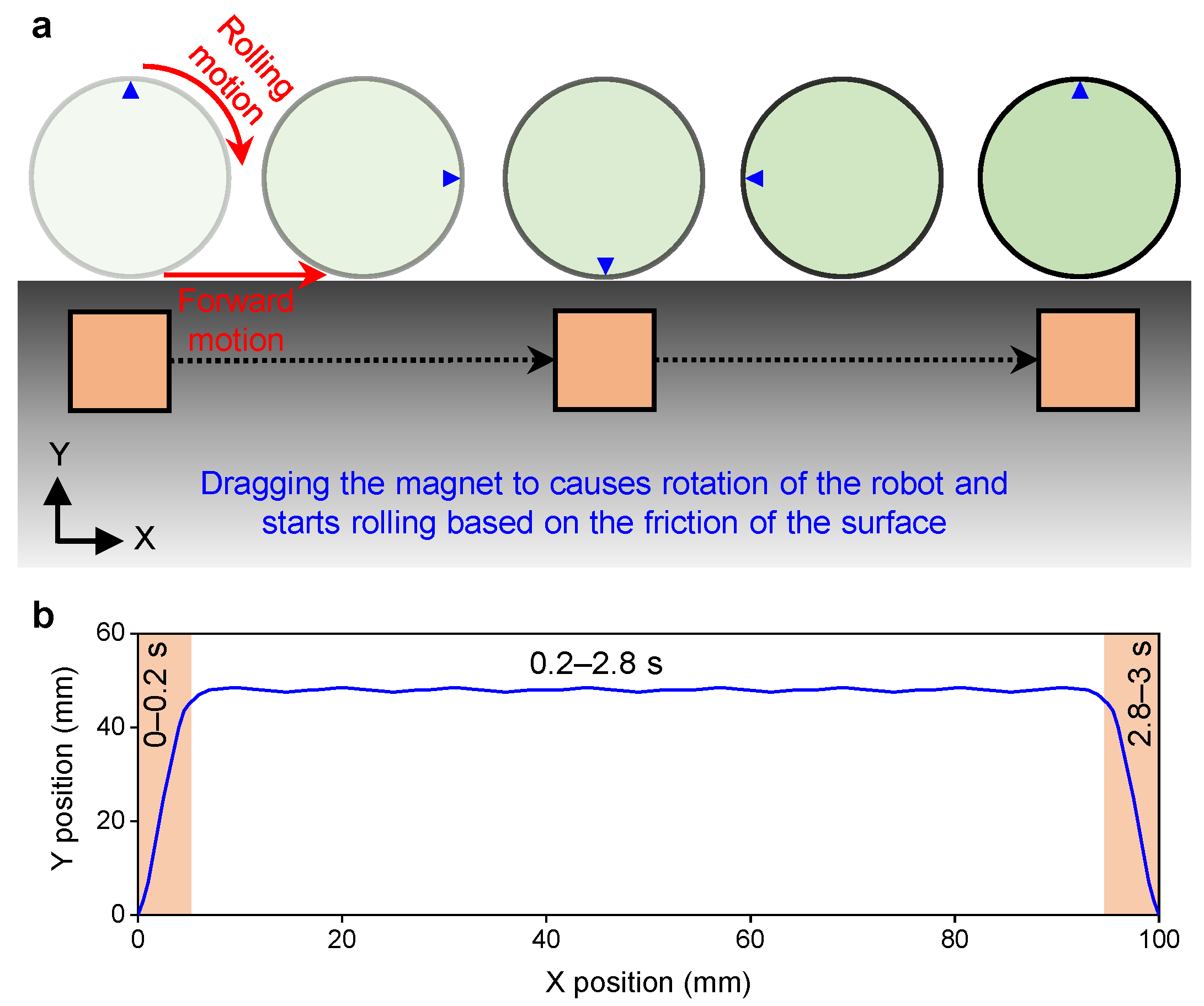
3.1.1. Rolling Motion

The robot can roll along its length by a specific motion of the actuation magnet. The schematic showing the actuation mechanism of the robot is shown in Figure 5a. The motion of the actuation magnet is shown in its X and Y position in Figure 5b. Initially, the actuating magnet is placed 50 mm away from the board and then raised ≈48 mm in ≈0.2 s. The actuating magnet is then displaced ≈90 mm along the X direction and then dropped 48 mm to inactivate the rolling motion. The displacement of the actuating magnet along the X-direction at ≈2 mm from the board occurs for ≈2.6 s, as shown in Figure 5b. When the actuating magnet is dragged along the X-direction, the robot rotates and rolls along the length of the robot (Figure 5a).
Amongst the three configurations, Design 3 shows the best rolling performance on board, sandpaper, and sand, and their time-lapse images are shown in Figure 6a–c respectively. The highest displacement and velocity of Design 3 is observed on board. In contrast, its lowest displacement and velocity are observed on sand, demonstrating the influence of the friction coefficient of the actuating substrate. The displacement along X and Y directions of the three configurations of the robot on board, sandpaper, and sand are shown in Figure 6d,f,h. Designs 1 and 2 indicate no displacement in both X and Y directions when actuated in all three environments (board, sandpaper, and sand), as shown in Figure 6d,f,h.
Design 3 demonstrates the ability to roll three cycles in 3 s when actuated on board, and one cycle in 3 s on sandpaper, and only 0.6 cycles in 3 s on sand. Since the X-direction is measured from the center of the robot. In contrast, Y-direction is measured from the base surface, the displacement values in X-direction varies from –5 mm to 5 mm. In comparison, the displacement values in the Y-direction vary from 0 mm to 10 mm, causing the displacement curve in X-direction to resemble a sine wave, while the displacement curve in Y-direction to resemble a rectified sine wave. The overall displacement and the velocities during the rolling motion of all three configurations on board, sandpaper, and sand are shown in Figure 6e,g,i. The overall displacement of Design 3 varies between 0 mm and 10 mm for all environments and shows a maximum velocity of ≈40 mm s 1 , ≈20 mm s 1 , and ≈10 mm s 1 on board, sandpaper, and sand, respectively. When three samples were tested under the same experimental conditions for the rolling motion, an error of ≈1 mm was observed in different environments.

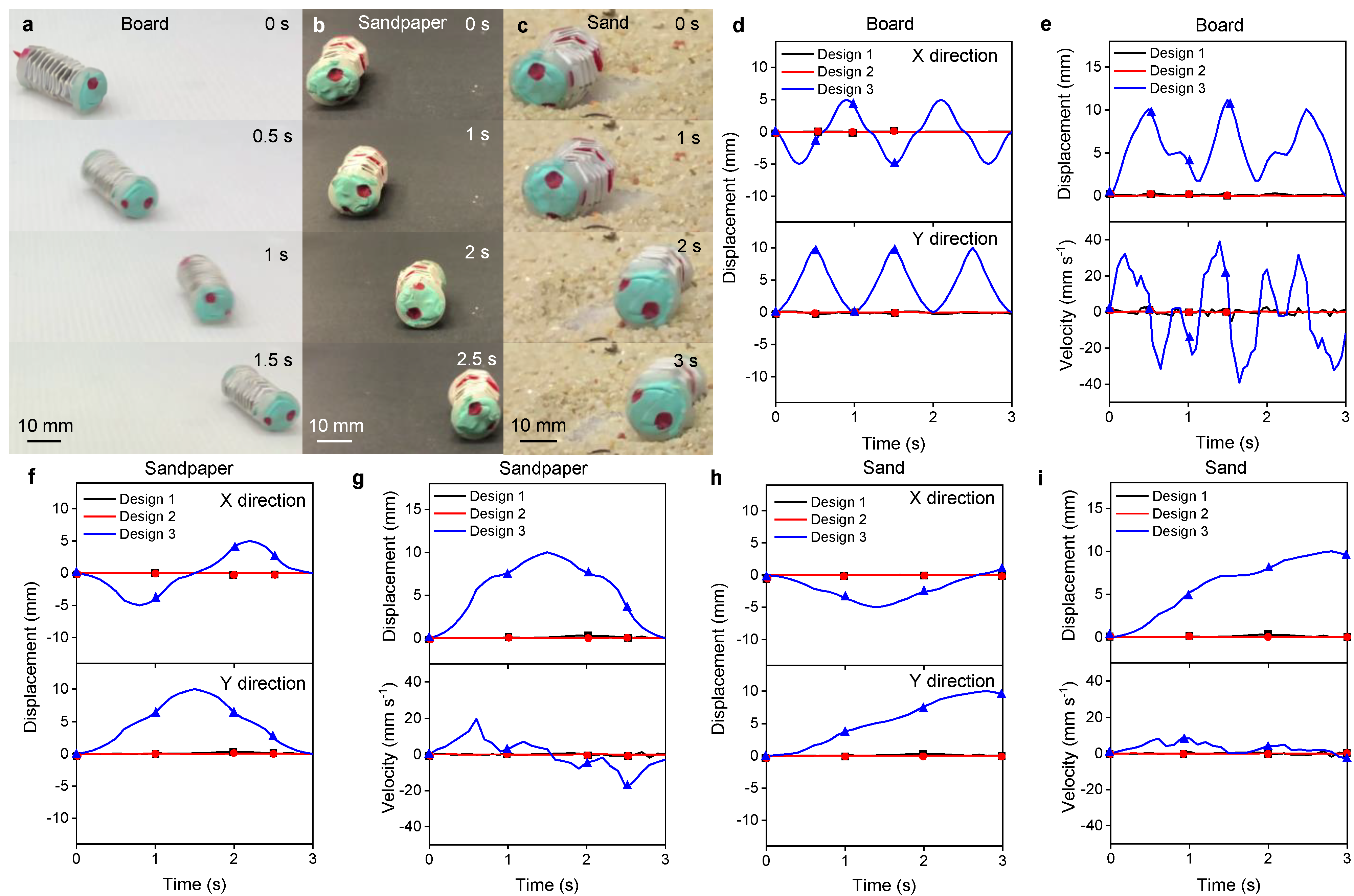
3.1.2. Turning Motion

The robot can bend or turn by actuating with a magnet in a specific motion. The schematic showing the actuation mechanism of the robot is shown in Figure 7a. The initial and final position of the robot and its overall displacement measurement are shown in Figure 7b. The path traced by the actuating magnet during actuation is shown in Figure 7c. Initially, the actuating magnet is placed 50 mm away from the board and then raised ≈50 mm in ≈2 s. During this, the actuating magnet is also moved 50 mm in the X-direction, as shown in Figure 7c. This movement of the actuating magnet in X and Y directions causes one end of the robot to move towards the magnet, displaying the turning or bending motion. The robot is placed on the base surface, and the displacement of the robot is observed in the X-Z direction instead of the X-Y direction.
Among the three configurations, Design 1 shows the best turning performance in all environments (board, sandpaper, and sand). The sequential pictures of the actuation of Design 1 on board, sandpaper, and sand are shown in Figure 8a–c, respectively. Design 1 shows its highest displacement and velocity on board. In contrast, its lowest displacement and velocity are observed on the sand, demonstrating the influence of the friction coefficient of the actuating substrate. The displacement along X and Y directions of the three configurations of the robot on board, sandpaper, and sand are shown in Figure 8d,f,h. All three configurations can perform turning motion in the three environments. Design 1 shows a displacement of ≈5.5 mm and ≈5.6 mm along the X-direction and Y-direction respectively when actuated on board, and ≈4.1 mm and ≈3.8 mm along the X-direction and Y-direction respectively when actuated in sandpaper, and ≈2.2 mm and ≈2.7 mm along the X-direction and Y-direction respectively when actuated in sand. Design 2 shows a displacement of ≈1.1 mm and ≈1.8 mm along X-direction and Y-direction respectively when actuated on board, and ≈0.2 mm and ≈0.3 mm along X-direction and Y-direction respectively on sandpaper, and no displacement in both X- and Y-direction on sand. Design 3 shows a displacement of ≈3.4 mm and ≈4.3 mm along X-direction and Y-direction respectively when actuated on board, and ≈0.1 mm and ≈1.2 mm along X-direction and Y-direction respectively on sandpaper, and ≈2.1 mm and ≈1.8 mm along the X-direction and Y-direction respectively on sand.
The overall displacement and velocity of the three configurations of the robot on three environments are shown in Figure 8e,g,i. Design 1 shows an overall displacement of ≈7.5 mm (≈180 ) and a maximum velocity of ≈62 mm s 1 when actuated on board, and an overall displacement of ≈6.9 mm (≈83 ) and a maximum velocity of ≈72 mm s 1 on sandpaper, and an overall displacement of ≈3.2 mm (≈58 ) and a maximum velocity of ≈28 mm s 1 on sand. Design 2 displays an overall displacement of ≈1.2 mm (≈10 ) and a maximum velocity of ≈13 mm s 1 when actuated on board, and an overall displacement of ≈1 mm (≈8 ) and a maximum velocity of ≈5.9 mm s 1 on sandpaper, and no overall displacement or velocity is observed on sand. Design 3 displays an overall displacement of ≈5.7 mm (≈70 ) and a maximum velocity of ≈44 mm s 1 when actuated on board, and an overall displacement of ≈1.9 mm (≈25 ) and a maximum velocity of ≈60 mm s 1 on sandpaper, and an overall displacement of ≈2.1 mm (≈32 ) and a maximum velocity of ≈30 mm s 1 on sand. When three samples were tested under the same experimental conditions for the turning motion, an error of less than 1 mm was observed in different environments.

4. Conclusions

We presented a magnetically actuated origami folded cylinder that can perform different locomotions (peristaltic, rolling, and turning) with the customized assembly of active materials. We compared the displacement and velocity profile of the proposed soft robot in different environments such as board, sandpaper, and sand. Based on the performance of different configurations, Design 1 is recognized to be the best for turning motion, while Design 3 proved to be the best for peristaltic and rolling movements. Design 3 also displayed promising results during turning motion, making it the best overall configuration. This is due to the spiral arrangement of the iron sheets, which improves its ability to be attracted by the permanent magnet regardless of its position (side or direction). Since understanding the details about the deformation in individual segments of the origami robot are difficult, more theoretical and force analysis will be performed in the future. The small size and the lightweight (≈1 g) of the robot facilitate deployment in narrow spaces. The untethered actuation mechanism also enables the robot to navigate through tortuous paths without any buckling. The size of the robot and the soft nature of the materials used in the fabrication of the robot restrains from damaging the tissues enabling its use in biomedical applications.
The developed robot demonstrates a maximum locomotion speed of ≈2.5 mm s 1 during peristaltic motion, which is significantly lesser than the other current bioinspired origami robots that showed a maximum speed of ≈13–23 mm s 1 [25,26] during peristaltic motion. Although the speed of the developed robot is lesser, this demonstrates different robotic motions which is not possible in the current high speed robots. Replacing the iron sheets (paramagnetic) with NdFeB materials (ferromagnetic) could increase the number of possible locomotions and improve navigation speed in specific complex pathways. Substituting the paper backbone with water-resistant materials such as PET (polyethylene terephthalate) or PEEK (polyether ether ketone) prepares it to be used in fluidic environments. In addition to water-resistant materials, incorporating biocompatible materials such as hydrogels can enable the device for utilization in biomedical applications. By attaching a small camera, the robot can be used as an endoscope for inspection, diagnosis, and treatment of oral cavities. The robot can carry a heavy load (up to 10 times its body weight) since the load-carrying capacity depends on the paper or backbone material used. However the actuation ability might be affected due to the addition of high stiffness material to the robot. The size of the robot can be further reduced by utilizing automated origami folding technologies for fabricating the robot. This can enable the robot to navigate through the small intestine in the GI (gastrointestinal) tract or nasal cavity and can also be used for biomedical applications due to the high contractibility and shape transformation characteristics of origami structures.

Author Contributions

Conceptualization, H.R.; methodology, H.R., M.S.K. and P.S.; validation, P.S., M.S.K. and H.R.; investigation, P.S.; resources, H.R; data curation, H.R., M.S.K. and P.S.; writing—original draft preparation, M.S.K., C.J.C., P.S. and H.R.; writing—review and editing, M.S.K., C.J.C. and H.R.; visualization, M.S.K., P.S. and H.R.; supervision, H.R.; project administration, H.R.; funding acquisition, H.R. All authors have read and agreed to the published version of the manuscript.

Funding

This work was supported by the Chinese University of Hong Kong (CUHK), Direct Grant 4055139 for research project on Multiphysics Study of Magnetically Deployable Robotic Collapsible Structures.

Institutional Review Board Statement

Not applicable.

Informed Consent Statement

Not applicable.

Data Availability Statement

Data available on request.

Conflicts of Interest

The authors declare no conflict of interest.

References

  1. Banerjee, H.; Pusalkar, N.; Ren, H. Single-motor controlled tendon-driven peristaltic soft origami robot. J. Mech. Robot. 2018, 10, 064501. [Google Scholar] [CrossRef] [Green Version]
  2. Yang, H.; Yeow, B.S.; Chang, T.H.; Li, K.; Fu, F.; Ren, H.; Chen, P.Y. Graphene Oxide-Enabled Synthesis of Metal Oxide Origamis for Soft Robotics. ACS Nano 2019, 13, 5410–5420. [Google Scholar] [CrossRef]
  3. Yang, H.; Yeow, B.S.; Li, Z.; Li, K.; Chang, T.H.; Jing, L.; Li, Y.; Ho, J.S.; Ren, H.; Chen, P.Y. Multifunctional metallic backbones for origami robotics with strain sensing and wireless communication capabilities. Sci. Robot. 2019, 4, 59. [Google Scholar] [CrossRef] [PubMed]
  4. Paez, L.; Agarwal, G.; Paik, J. Design and analysis of a soft pneumatic actuator with origami shell reinforcement. Soft Robot. 2016, 3, 109–119. [Google Scholar] [CrossRef]
  5. Zhai, Z.; Wang, Y.; Jiang, H. Origami-inspired, on-demand deployable and collapsible mechanical metamaterials with tunable stiffness. Proc. Natl. Acad. Sci. USA 2018, 115, 2032–2037. [Google Scholar] [CrossRef] [Green Version]
  6. Reid, A.; Lechenault, F.; Rica, S.; Adda-Bedia, M. Geometry and design of origami bellows with tunable response. Phys. Rev. E 2017, 95, 013002. [Google Scholar] [CrossRef] [Green Version]
  7. Wang, F.; Gong, H.; Chen, X.; Chen, C. Folding to curved surfaces: A generalized design method and mechanics of origami-based cylindrical structures. Sci. Rep. 2016, 6, 33312. [Google Scholar] [CrossRef] [PubMed] [Green Version]
  8. Schenk, M.; Viquerat, A.D.; Seffen, K.A.; Guest, S.D. Review of inflatable booms for deployable space structures: Packing and rigidization. J. Spacecr. Rocket. 2014, 51, 762–778. [Google Scholar] [CrossRef] [Green Version]
  9. Cowan, B.; Von Lockette, P.R. Fabrication, characterization, and heuristic trade space exploration of magnetically actuated Miura-Ori origami structures. Smart Mater. Struct. 2017, 26, 045015. [Google Scholar] [CrossRef]
  10. Kuribayashi, K.; Tsuchiya, K.; You, Z.; Tomus, D.; Umemoto, M.; Ito, T.; Sasaki, M. Self-deployable origami stent grafts as a biomedical application of Ni-rich TiNi shape memory alloy foil. Mater. Sci. Eng. A 2006, 419, 131–137. [Google Scholar] [CrossRef]
  11. Camarillo, D.B.; Milne, C.F.; Carlson, C.R.; Zinn, M.R.; Salisbury, J.K. Mechanics modeling of tendon-driven continuum manipulators. IEEE Trans. Robot. 2008, 24, 1262–1273. [Google Scholar] [CrossRef]
  12. Dong, S. Review on piezoelectric, ultrasonic, and magnetoelectric actuators. J. Adv. Dielectr. 2012, 2, 1230001. [Google Scholar] [CrossRef]
  13. Conway, N.J.; Traina, Z.J.; Kim, S.G. A strain amplifying piezoelectric MEMS actuator. J. Micromech. Microeng. 2007, 17, 781. [Google Scholar] [CrossRef]
  14. Bowen, L.; Springsteen, K.; Frecker, M.; Simpson, T. Trade space exploration of magnetically actuated origami mechanisms. J. Mech. Robot. 2016, 8, 031012. [Google Scholar] [CrossRef]
  15. Onal, C.D.; Wood, R.J.; Rus, D. An origami-inspired approach to worm robots. IEEE/ASME Trans. Mechatron. 2012, 18, 430–438. [Google Scholar] [CrossRef]
  16. Kalairaj, M.S.; Banerjee, H.; Lim, C.M.; Chen, P.Y.; Ren, H. Hydrogel-matrix encapsulated Nitinol actuation with self-cooling mechanism. RSC Adv. 2019, 9, 34244–34255. [Google Scholar] [CrossRef] [Green Version]
  17. Kalairaj, M.S.; Yeow, B.S.; Lim, C.M.; Ren, H. Nitinol actuated soft structures towards transnasal drug delivery: A pilot cadaver study. Med Biol. Eng. Comput. 2020, 58, 611–623. [Google Scholar] [CrossRef]
  18. Kalairaj, M.S.; Yeow, B.S.; Lim, C.M.; Ren, H. Needle-size bending actuators based on controlled nitinol curvatures and elastic structures. J. Mech. Robot. 2020, 12, 031015. [Google Scholar] [CrossRef]
  19. Banerjee, H.; Sivaperuman Kalairaj, M.; Chang, T.H.; Fu, F.; Chen, P.Y.; Ren, H. Highly Stretchable Flame-Retardant Skin for Soft Robotics with Hydrogel–Montmorillonite-Based Translucent Matrix. Soft Robot. 2021. [Google Scholar] [CrossRef] [PubMed]
  20. Zhang, S.; Ke, X.; Jiang, Q.; Ding, H.; Wu, Z. Programmable and reprocessable multifunctional elastomeric sheets for soft origami robots. Sci. Robot. 2021, 6, eabd6107. [Google Scholar] [CrossRef]
  21. Tang, D.; Zhang, C.; Sun, H.; Dai, H.; Xie, J.; Fu, J.; Zhao, P. Origami-inspired magnetic-driven soft actuators with programmable designs and multiple applications. Nano Energy 2021, 89, 106424. [Google Scholar] [CrossRef]
  22. Salerno, M.; Firouzeh, A.; Paik, J. A low profile electromagnetic actuator design and model for an origami parallel platform. J. Mech. Robot. 2017, 9, 041005. [Google Scholar] [CrossRef]
  23. Cai, C.J.; Xiao, X.; Kalairaj, M.S.; Lee, I.J.J.; Mugilvannan, A.K.; Yeow, B.S.; Tan, J.H.; Huang, H.; Ren, H. Diversified and untethered motion generation via crease patterning from magnetically actuated caterpillar-inspired origami robot. IEEE/ASME Trans. Mechatron. 2020, 26, 1678–1688. [Google Scholar] [CrossRef]
  24. Xiang, X.; Lu, G.; Ruan, D.; You, Z.; Zolghadr, M. Large deformation of an arc-Miura structure under quasi-static load. Compos. Struct. 2017, 182, 209–222. [Google Scholar] [CrossRef]
  25. Fang, H.; Zhang, Y.; Wang, K. Origami-based earthworm-like locomotion robots. Bioinspir. Biomimet. 2017, 12, 065003. [Google Scholar] [CrossRef] [PubMed]
  26. Zhang, Q.; Fang, H.; Xu, J. Yoshimura-origami Based Earthworm-like Robot With 3-dimensional Locomotion Capability. Front. Robot. AI 2021, 8, 271. [Google Scholar] [CrossRef]
Figure 1. (a) Steps involved in the folding of the origami robot. (b) Design 1 arrangement of iron sheets in origami robot. (c) Design 2 arrangement of iron sheets in origami robot. (d) Design 3 arrangement of iron sheets in origami robot.
Robotics 10 00118 g001
Figure 2. (a) Schematic showing the actuation mechanism of peristaltic motion of the soft robot actuated by a permanent magnet. (b) Pathway of the actuating magnet to generate the peristaltic motion of the robot.
Robotics 10 00118 g002
Figure 3. Performance of the peristaltic motion. (a) Time-lapse images of the peristaltic motion of the Design 3 origami robot inboard. (b) Time-lapse images of the peristaltic motion of the Design 3 origami robot in sandpaper. (c) Time-lapse images of the peristaltic motion of the Design 3 origami robot in the sand. (d) Time-resolved displacement in X and Y directions of the origami robot on board. (e) Time-resolved displacement and velocity of the origami robot on board. (f) Time-resolved displacement in X and Y directions of the origami robot in sandpaper. (g) Time-resolved displacement and velocity of the origami robot in sandpaper. (h) Time-resolved displacement in X and Y directions of the origami robot in sand. (i) Time-resolved displacement and velocity of the origami robot in sand.
Robotics 10 00118 g003
Figure 4. Performance of the individual segment during peristaltic motion. (a) Time-lapse images of the peristaltic motion of the Design 3 origami robot on board. (b) Time-lapse images of the peristaltic motion of the Design 3 origami robot in sandpaper. (c) Time-lapse images of the peristaltic motion of the Design 3 origami robot in the sand. (d) Time-resolved displacement in X and Y directions of the origami robot on board. (e) Time-resolved displacement and velocity of the origami robot on board. (f) Time-resolved displacement in X and Y directions of the origami robot in sandpaper. (g) Time-resolved displacement and velocity of the origami robot in sandpaper. (h) Time-resolved displacement in X and Y directions of the origami robot in the sand. (i) Time-resolved displacement and velocity of the origami robot in sand.
Robotics 10 00118 g004
Figure 5. (a) Schematic showing the actuation mechanism of the rolling motion of the robot. (b) Pathway of the actuating magnet to generate the rolling motion of the robot.
Robotics 10 00118 g005
Figure 6. Performance of the rolling motion. (a) Time-lapse images of rolling motion of the Design 3 origami robot on board. (b) Time-lapse images of rolling motion of the Design 3 origami robot in sandpaper. (c) Time-lapse images of rolling motion of the Design 3 origami robot in sand. (d) Time-resolved displacement in X and Y directions of the origami robot on board. (e) Time-resolved displacement and velocity of the origami robot on board. (f) Time-resolved displacement in X and Y directions of the origami robot in sandpaper. (g) Time-resolved displacement and velocity of the origami robot in sandpaper. (h) Time-resolved displacement in X and Y directions of the origami robot in the sand. (i) Time-resolved displacement and velocity of the origami robot in sand.
Robotics 10 00118 g006
Figure 7. (a) Schematic showing the actuation mechanism of turning motion of the soft robot actuated by a permanent magnet. (b) Schematic showing the displacement in the body of the robot during turning motion. (c) Pathway of the actuating magnet to generate the turning motion of the robot.
Robotics 10 00118 g007
Figure 8. Performance of the turning motion. (a) Time-lapse images of turning motion of the Design 1 origami robot on board. (b) Time-lapse images of turning motion of the Design 1 origami robot in sandpaper. (c) Time-lapse images of turning motion of the Design 1 origami robot in sand. (d) Time-resolved displacement in X- and Y-directions of the origami robot on board. (e) Time-resolved displacement and velocity of the origami robot on board. (f) Time-resolved displacement in X- and Y-directions of the origami robot in sandpaper. (g) Time-resolved displacement and velocity of the origami robot in sandpaper. (h) Time-resolved displacement in X- and Y-directions of the origami robot in the sand. (i) Time-resolved displacement and velocity of the origami robot in sand.
Robotics 10 00118 g008
Publisher’s Note: MDPI stays neutral with regard to jurisdictional claims in published maps and institutional affiliations.

