Article

Monte Carlo FLUKA Simulation of Gamma Backscattering for Rebar Detection in Reinforced Concrete with Basaltic Aggregates

by
Alexandre Osni Gral Iori
and
Emerson Mario Boldo
*
Center of Exact and Technological Sciences, State University of Western Paraná–UNIOESTE, Cascavel 85819-110, Paraná, Brazil
*
Author to whom correspondence should be addressed.
Atoms 2025, 13(7), 67; https://doi.org/10.3390/atoms13070067
Submission received: 8 April 2025 / Revised: 5 July 2025 / Accepted: 7 July 2025 / Published: 9 July 2025
(This article belongs to the Section Nuclear Theory and Experiments)

Abstract

Compton backscattering is a versatile non-destructive technique for material characterization and structural evaluation in reinforced concrete. This methodology enables a single-sided inspection of large structures—which is particularly useful where only one side of the material is accessible for examination—is relatively inexpensive, and can be made portable for field applications. This study aims to assess the influence of basaltic coarse aggregates on the accurate localization and dimensioning of rebar in reinforced concrete using the gamma-ray Compton backscattering technique at two distinct incident photon energies—59.5 keV and 1170 keV. The analysis was performed through Monte Carlo simulations using the FLUKA code, providing insights into the feasibility and limitations of this non-destructive method for structural evaluation. Both photon energies successfully detected the rebar embedded at a 3 cm depth in mortar, achieving a good spatial resolution and contrast, despite the presence of a significant amount of iron oxide within the aggregate. Among the evaluated sources, 60Co yielded the highest contrast and count values, demonstrating its potential for rebar detection at greater depths within concrete structures. The single-sided Compton scattering technique proved to be effective for the investigated application and presents a promising alternative for the non-destructive assessment of real-world reinforced concrete structures.

1. Introduction

Concrete is composed of cement, coarse aggregate, fine aggregate, water, and (when required) chemical additives. Structurally, it is characterized by a high compressive strength but a low tensile strength [1]. Due to concrete’s inherent weakness in tension, a steel reinforcement is added to form a composite material (reinforced concrete) that combines the compressive strength of concrete with the tensile strength of steel.
Reinforced concrete structures are extensively employed in civil engineering, particularly in the construction of large buildings [2]. These structures are frequently exposed to various environmental degradation factors, which can ultimately lead to the development of pathologies that significantly compromise their durability and mechanical performance [3,4]. Among these pathologies, reinforcement corrosion stands out as one of the most critical and prevalent issues, affecting both the esthetic and structural integrity of reinforced concrete structures [5].
Therefore, conducting periodic inspections of these structural elements is essential to detect this pathology at an early stage and prevent structural compromise. Given that, in the absence of an intervention, corrosion progresses continuously in nearly all cases, and timely identification and mitigation measures are crucial to preserving the integrity of the structure.
Gamma-ray Compton scattering can be a viable technique for this application. This physical phenomenon constitutes one of the fundamental interaction mechanisms between ionizing radiation and matter. The process occurs when an incident photon undergoes inelastic scattering with a bound atomic electron, resulting in a scattered photon with a reduced energy and modified trajectory [6].
In a standard implementation of this technique, a well-collimated gamma-ray beam is directed onto the target sample, while a detector positioned at a fixed angle registers the backscattered photons originating from Compton interactions within the target material [7]. The intensity of the detected signal depends on the electronic density of the material volume intersected by the incident beam and detector. While this approach typically requires longer acquisition times compared to transmission-based radiography (X-ray/gamma) and necessitates point-by-point signal reconstruction, it offers distinct advantages: a relatively low cost, the effective penetration of gamma-rays into matter, and single-sided access requirements enabling the in situ structural evaluation of large structures [8].
Recent studies have employed Compton scattering to detect flaws, inhomogeneity, voids, cracks, and inclusions in concrete [9,10,11,12,13,14]. However, the samples analyzed in these studies were composed of mortar (a mixture of cement, sand, and water) without the addition of coarse aggregates. Coarse aggregates, such as gravel, are essential components of reinforced concrete. These crushed stones, often of a basaltic origin, contain heavy metals such as iron and titanium. The presence of metallic components can significantly attenuate both the incident and scattered radiation, depending on the energy of the incident radiation. This attenuation may compromise the accuracy of the rebar localization and dimensional assessment—a critical first step in a corrosion evaluation, as the cross-sectional area reduction serves as a primary indicator of steel deterioration [15]. The only study that incorporated aggregates into the concrete base of the samples utilized a high-energy gamma-ray source (137Cs) [16]. Despite the good results in locating the steel reinforcement bars, the use of high-energy sources can hinder the feasibility of applying the technique in a portable manner, as they require extensive radiation shielding for operator safety. To address this limitation while maintaining the inspection capability, this work evaluates two strategic energy extremes: 241Am (59.5 keV) for its reduced shielding needs and field applicability and 60Co (1170 keV) as a benchmark for deeper penetration scenarios. Therefore, the objective of this work was to evaluate the influence of crushed stone aggregates on reinforced concrete rebar detection using Compton backscattering at these optimized energies. This study was carried out using a Monte Carlo simulation.

2. Physical Basis of Compton Scattering

In the energy range encompassing most nuclear transitions, specifically between 0.01 and 10 MeV, an incident photon interacts with matter primarily through three mechanisms: the photoelectric effect, scattering (either coherent or incoherent), and pair production. Within the range of 150 keV to 3 MeV, incoherent scattering—commonly referred to as Compton scattering—predominates, particularly in target materials with low to intermediate atomic numbers, such as soil, concrete, metals, and biological tissues.
In this process, an incident photon undergoes an inelastic collision with an orbital electron, transferring a portion of its energy and scattering into a specific solid angle. Given that the photon’s energy significantly exceeds the typical binding energies of electrons in atoms, the electron is treated as free and at rest. As a result of this interaction, the electron is ejected from the atom, with its direction of motion governed by the conservation laws of relativistic energy and momentum.
The energy of the scattered photon E is exclusively related to the energy of the incident photon E0 and the angle θ of scattering by [17]
E = E 0 1 + E 0 m 0 c 2 ( 1 c o s θ )
where m0c2 is the electron’s rest energy with a value equal to 511 keV.
As previously discussed, a typical experiment employing Compton backscattering consists of directing a well-collimated gamma radiation beam toward a sample and detecting the photons that are backscattered by the material. These scattered photons are then counted by a detector, with both the radiation source and the detector positioned on the same side of the sample. A simplified schematic of the experimental setup is presented in Figure 1.
The scattering volume, also referred to as the inspection volume (VOL), is the region in which the fields of view of both the radiation source and the detector overlap. The size of this volume is a key factor influencing the spatial resolution of the experiment. As the VOL is systematically scanned across the sample, with both the source and detector moving in unison, the number of backscattered photons from the regions of interest within the material is recorded by the detector.
According to the single scattering model [18], photons are subject to continuous attenuation (primarily via Compton scattering and photoelectric absorption) before undergoing a definitive interaction within the volume of interest. Upon interaction, they are scattered within the VOL and subsequently attenuated as they travel toward the detector. This scattering process primarily involves electron–photon interactions governed by the Compton mechanism, where incident photons transfer energy to atomic electrons and emerge with reduced energy at a scattering angle θ. Photons will be deflected at a certain angle and scattering energy. The angular and energy distribution of these scattered photons is characterized by the differential cross-section per solid angle (dσ/dΩ), described by the Klein–Nishina formula [19]:
d σ d Ω = Z r 0 2 2 1 + c o s 2 θ 1 1 + α ( 1 c o s θ ) 2 1 + α 2 ( 1 c o s θ ) 2 ( 1 + α ( 1 c o s θ ) ( 1 + c o s 2 θ )  
where Z is the atomic number, α = E/m0c2, r0 is the classical electron radius (2.82 fm), and θ is the scattered photon angle.
The intensity of the signal captured by the detector (Nc) can be obtained using the following Equation (3) [20]:
N C = I 0 t ε exp x 1 μ 1 ( E ) d x exp x 2 μ 2 ( E ) d x ρ e d σ d Ω Δ Ω V + M ,
where I0 is the intensity of the incident beam with energy E, t is the time in seconds of the counting period, ε is the detector efficiency for the scattered photon energy, x1 and x2 are the paths taken inside the material by the incident and scattered photons, respectively, µ1 and µ2 are linear attenuation coefficients for the respective paths taken, ρe is the electronic density of the material, / is the electron differential cross-section of the Compton effect as shown in Equation (2), ΔΩ is the solid sample–detector angle, and V is the radiated voxel volume (VOL), which is defined by the overlap of the solid angles of the beam and the detector collimation. Finally, the term M quantifies the contribution of multiple scattering events, where photons undergo successive Compton interactions outside the inspection volume before reaching the detector. The proper collimation of the source and detector significantly reduces this contribution [21]. Additionally, the multiple scattering contribution can be further mitigated by a spectral analysis if only photons within the Compton peak energy window were integrated, systematically excluding the low-energy tail formed by multiply-scattered photons [22].
Therefore, the total contribution of photons scattered by the Compton effect is dependent on the electron density of the target material (ρe). The electron density, i.e., the number of electrons per cm3, is given by
ρ e = ρ N A Z A  
where ρ is the density of the material (g/cm3), NA is Avogadro’s number, Z is the atomic number, and A is the atomic weight. For materials with a low atomic number, (Z/A) ≅ 1/2 (except hydrogen and hydrogenous material), and then Equation (4) can be written as
ρ e N A 2 ρ  
in other words, ρe is directly proportional to ρ.
This principle enables a density-selective inspection, where localized variations in density (e.g., voids or inclusions) modulate the scattered photon intensity.
We can then define what we will call the Density Contrast between two materials [23]. It is the fractional change in the flux of scattered photons due to inhomogeneity in the sample and can be determined mathematically by the following equation:
C A B = ( A ¯ B ¯ ) A ¯ × 100 %
where CAB is the contrast between material A in relation to material B; A ¯ and B ¯ are the averages of the integrated counts recorded by the detector at the points where the VOL intersects material A and B, respectively.
The contrast value can also assess the experiment’s ability to distinguish between materials of different densities within the sample. The experimental setup should be optimized to obtain the highest possible Density Contrast values.

3. Materials and Methods

3.1. Monte Carlo Simulation

FLUKA (FLUktuierende KAskade) version 4-3.0, installed on Ubuntu 20.04.6 LTS, was used to perform the simulations in this study [24,25]. FLUKA is a fully integrated Monte Carlo simulation package designed for particle transport through matter, making it particularly well-suited for scattering problems. It accurately simulates the interaction and propagation of photons in matter, with incident energies starting at 1 keV. Specifically, for the Compton effect, the software accounts for atomic bonding when calculating scattering probabilities, employing inelastic Hartree–Fock form factors [26]. The results obtained with FLUKA have been previously evaluated against both experimental data and theoretical predictions from other simulation codes, demonstrating excellent agreement between them [27,28,29].
Additionally, FLUKA incorporates an advanced user interface, FLAIR [30], which facilitates the editing of input files, the construction of simulation geometries, the execution of computational codes, and the generation of graphical outputs using the Gnuplot utility. This functionality enhances the visualization and analysis of output data.
In FLUKA, simulation parameters are defined using input cards. The energy of the gamma-ray source and the characteristics of the incident beam are specified using the BEAM and BEAMPOS cards, respectively. The GEOMETRY card defines the simulation’s spatial configuration, including the shape and positioning of the sample, collimator, and detector. The material composition of all simulated objects is assigned using the MATERIAL, COMPOUND, and ASSIGNMA cards. To quantify backscattered photons, the FLUKA USRBDX card was configured for one-way current scoring across the detector boundary. This implementation records only particles crossing into the detector volume. The USRBDX scoring inherently provides normalized result outputs to per-primary-particle units (after post-processing conducted in FLAIR), integrating automatically over energy and angle. The last card used in the simulations of this work is the USRBIN, which scores photon fluence distribution in a regular spatial structure (binning detector) independent from the geometry.

3.2. Study Case

The sample modeled in the simulation consists of a cement column (with dimensions of 8.0 × 20.0 × 20.0 cm and a density of 2300 kg/m3), containing a centrally positioned steel rebar (7850 kg/m3), with a diameter of 1.0 cm, embedded at a depth of 3 cm from the surface, as illustrated in Figure 2. In this initial study, we modeled a single rectangular coarse aggregate measuring 2.0 × 1.0 cm, centered on the rebar. Although this is a simple model, the rectangular shape maximizes the dimensions of a real irregular coarse aggregate and captures key scattering effects allowing analysis of aggregate interference. Furthermore, given its dimensions, this size is commonly used in various structural elements—such as columns, beams, and slabs—in the construction of large buildings [31].
Additionally, the selected gravel is of basaltic origin, one of the most commonly used types in civil construction [32]. In most countries, the majority of aggregates used in crushed concrete are derived from igneous rocks, which are formed through the cooling and solidification of magma [33]. These rocks are primarily composed of oxides of silicon, iron, aluminum, calcium, magnesium, sodium, titanium, and potassium [34]. Basaltic gravel used in this paper has a density of 2800 kg/m3, and its chemical composition is presented in Table 1 [35].
While Fe2O3 constitutes 15.5% of the aggregate’s composition (Table 1)—less abundant than SiO2—its influence on photon attenuation is disproportionately high due to iron’s atomic number (Z = 26 vs. Z = 14 for silicon). At source energies used in this work, the photoelectric cross-section scales as Z4–5 [36], making Fe2O3’s attenuation contribution greater than SiO2’s per unit mass, despite the lower concentration.
The collimator is composed of a cylindrical lead shell with an outer radius of 1.5 cm, an inner radius of 0.5 cm, and a height of 3 cm. Its primary function is to reduce the size of the inspection volume (VOL), thereby enhancing the spatial resolution of the experiment. Additionally, the collimator suppresses the detection of photons from multiple scattering events within the sample, as such photons deviate from their original trajectory and are absorbed by the lead shielding—a high-Z material with superior attenuation properties.
Positioned inside the collimator is a cylindrical cadmium telluride (CdTe) crystal with an approximate volume of 1.18 cm3, which functions as a detector by absorbing the backscattered photons incident upon it. For the purposes of the simulation, the detection crystal is assumed to operate with 100% efficiency—that is, every photon that reaches the crystal is recorded. The detector is positioned 10 cm from the center of the steel rebar and oriented at an angle of 135° relative to the direction of beam incidence. This angle maximizes the differential cross-section for Compton scattering, particularly for our lower-energy source (59.5 keV), as the Klein–Nishina formula (Equation (2)) predicts higher scatter probability at backward angles (>90°) while maintaining sufficient source–detector clearance. A 10 cm detector distance balanced signal intensity with practical setup limitations (equipment size, shielding, and sample accessibility), ensuring feasibility for real-world implementation.

3.3. Beam Energies and Scanning Positions

The sources used in the simulation were as follows: Americium 241 (59.51 keV) and Cobalt 60 (1170 and 1332 keV). The selection of these isotopes was based on findings from our previous study [37], which demonstrated superior contrast values for these isotopes in backscatter imaging of dense materials compared to 57Co (122.1 keV), 133Ba (356 keV), and 137Cs (662 keV). While 137Cs (662 keV) represents the widely adopted source for backscatter applications, its predominant use in the literature reflects a compromise between the excessive shielding requirements of high-energy sources like 60Co and the limited penetration of lower-energy alternatives. However, this work also targets field applications where minimizing radiological protection is critical, by validating 241Am as an effective low-energy source, which reduces shielding requirements. Such reduction in radiological protection needs addresses critical barriers to real-world implementation, particularly for mobile or resource-constrained inspection scenarios, while maintaining sufficient detection capability for near-surface features. Also, these two gamma sources possess long half-lives, ensuring extended operational durability.
The scan points selected for the incidence of the cylindrical “pencil” beam with a diameter of 1.0 mm are illustrated in Figure 3. At each point, 1.0 × 10⁶ photons were emitted. Considering a Cartesian coordinate system with the center of the rebar defined as the origin, the beam was directed at points ranging from −1.5 cm to 1.5 cm along one axis, with an interval of 0.3 cm between consecutive points. This configuration ensures that at least three scan points are located within each material composing the sample.

4. Results and Discussion

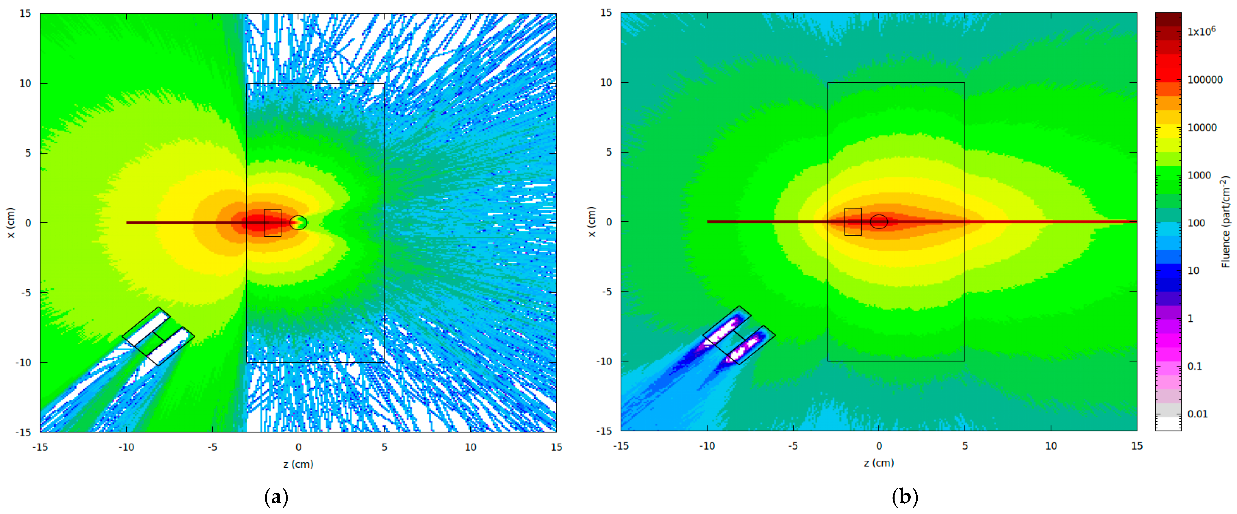
Using fluence maps generated by the USRBIN estimator in FLUKA, it is possible to analyze the scattering pattern of the beam upon its interaction with the target after the complete incidence of particles, as well as the attenuation effects that occur when the beam interacts with materials of different densities within the sample. Figure 4 presents the fluence distributions (binning x = 300, z = 300) for both beam energies employed in this study, corresponding to the central incidence on the sample (at coordinate x = 0 cm).
The scattering pattern and the number of photons scattered per unit solid angle depend on the energy of the incident photons, as described by the differential Compton cross-section given by the Klein–Nishina equation (Equation (2)). At low photon energies (i.e., when α = E/mc2 << 1), the Klein–Nishina cross-section approaches the classical Thomson scattering limit. In this regime, the scattering is essentially elastic, and the angular distribution becomes approximately symmetric around 90°, indicating an equal likelihood of forward and backward scattering. However, as the photon energy increases (α ˃˃ 1), the cross-section becomes increasingly asymmetric, with a marked reduction in the probability of backscattering.
The fluence maps illustrate this behavior, along with the attenuation effects caused by the interaction of the beam with materials of varying densities within the sample. For instance, it can be observed that the lower-energy beam emitted by the 241Am source undergoes almost a complete attenuation upon intersecting with the steel rebar.
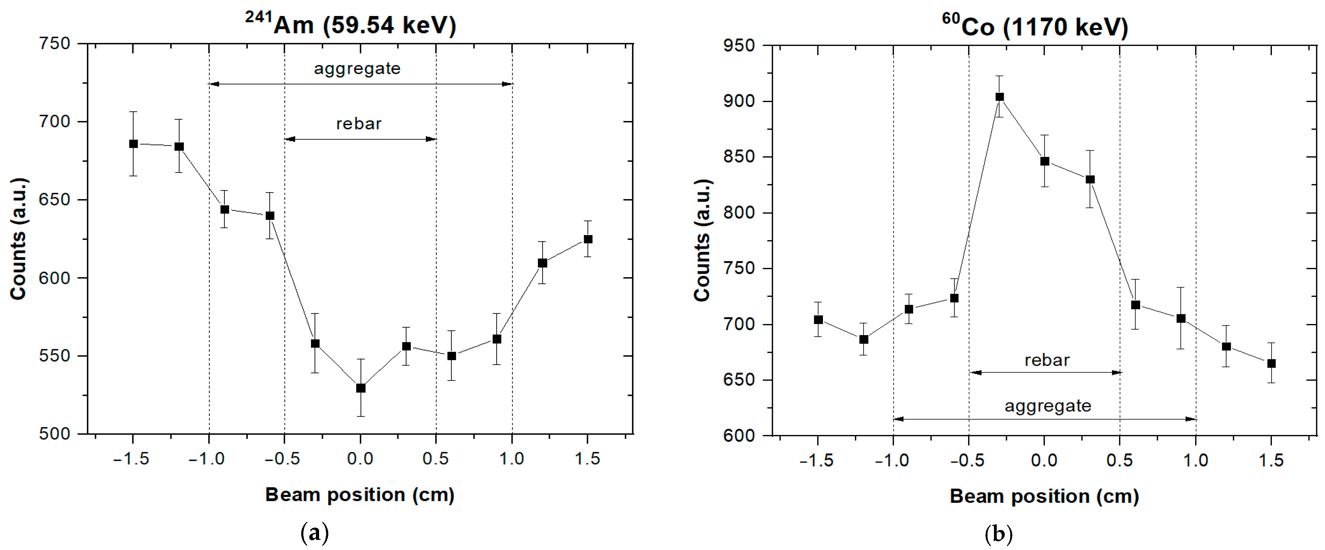
The backscattered photon counts obtained from the scans using the two radioactive sources, 241Am and 60Co, are presented in Figure 5. Each data point in the graph represents the integrated net count of the Compton photopeak corresponding to the respective scan positions previously indicated in Figure 3.
For the 241Am energy case (Figure 5a), when the inspection volume (VOL) intersects the aggregate region within the sample, a slight decrease in the number of scattered photons is observed between the cement matrix and the aggregate. Although the density difference between these two materials is relatively small (2300 and 2800 kg/m3, respectively), the low-energy beam emitted by the americium source demonstrated sensitivity to this variation due to attenuation. When the beam is focused on the region containing the steel rebar, a noticeable drop in photon counts occurs due to the attenuation of both the incident and scattered beams within the denser material. The three scan points with the lowest counts clearly indicate the location and approximate size of the rebar, despite its position behind an aggregate that contains a high percentage of Fe2O3—a component with a high density (5240 kg/m3). The reduced counts observed at the scan positions on the positive side (from 0.5 to 1.5 cm) can be attributed to the attenuation experienced by the photons as they return to the detector after scattering within the inspection volume. The asymmetry in the photon counts between the negative and positive scan positions represents a significant limitation of this experimental configuration, as it compromises the spatial resolution and hinders the accurate determination of the inclusion size. As the VOL moves away from the inclusion, this effect gradually diminishes. Eventually, both the incident and scattered beams propagate exclusively through the cement matrix, and the photon counts return to their initial levels.
In the case of 60Co (Figure 5b), the differentiation of the material densities based on the number of backscattered photons is also observed. However, unlike the lower-energy case, the higher-density steel rebar now produces a more pronounced scattering signal, as evidenced by the increased counts at the three scan points located between positions −0.5 and 0.5 cm. Due to the high energy of the gamma beam emitted by this isotope, the scattering phenomenon becomes predominant over attenuation. This behavior can be attributed to the fact that, at higher photon energies, Compton scattering becomes the dominant interaction mechanism, and the probability of scattering increases with the electron density. As a result, in this case, dense materials like the steel rebar produce a stronger backscattered signal than concrete [38]. While the 60Co source enables an accurate rebar localization due to its high penetration capability, its effectiveness in distinguishing between cement and gravel is limited by two fundamental factors at these energies: (1) the Compton scattering cross-section becomes less dependent on the atomic number (Z), reducing the sensitivity to the modest electron density difference between these materials, and (2) the mass attenuation coefficients of the cement and aggregate converge at MeV energies, minimizing the contrast in transmitted or backscattered signals [39,40]. Variations in photon counts between adjacent positions within the same material are attributed to statistical fluctuations inherent in Poisson-distributed radiation detection. For detected counts (Nc), the relative standard deviation (RSD) of counts is expected to be 1/√NC [19].
The Density Contrast values obtained for this test are presented in Table 2. These values are consistent with the observations from the direct analysis of the graphs, indicating that the presence of the basaltic coarse aggregate in front of the reinforcement does not significantly hinder the identification of its position—particularly when using the higher-energy 60Co source. In the simulated configuration, the sample includes a 2.5 cm cement cover, and the presence of the coarse aggregate along the path of the incident beam did not substantially interfere with the localization of the reinforcement, even when using the lower-energy 241Am source, which is more susceptible to attenuation by basaltic aggregates.
These findings demonstrate that low-energy sources such as 241Am can be effectively used to detect dense inclusions at shallow depths, which is particularly advantageous for the development of portable inspection systems. Meanwhile, 60Co yielded a slightly higher contrast value, as its high-energy photons are less attenuated by the elements present in the aggregate composition, further reinforcing its effectiveness in deeper or more challenging detection scenarios.

5. Conclusions

This study evaluated the influence of basaltic coarse aggregates on the detection and localization of steel reinforcements within concrete structures using the Compton backscattering technique. This investigation was conducted through Monte Carlo simulations performed with the FLUKA code. The two photon energies analyzed (59.51 keV and 1170 keV) successfully detected the rebar obscured by the basaltic aggregate, achieving satisfactory spatial resolution and contrast values, despite the aggregate’s high iron oxide content.
Among the sources studied, 60Co yielded a slightly higher contrast along with superior backscattered photon counts. While the contrast difference was small under these simulated conditions, this result, combined with the deeper penetration capability of its high-energy photons, supports its potential suitability for applications involving reinforcements located farther from the surface. However, its high-energy emissions necessitate robust radiation shielding—a critical consideration for field deployment. On the other hand, the lower-energy 241Am source demonstrated promising results for shallower inspections, suggesting its viability in portable, field-deployable systems.
The results confirm that the one-sided Compton scattering technique is effective for the problem under consideration and presents itself as a promising non-destructive testing method for the evaluation of reinforced concrete structures in real-world scenarios, where the routine monitoring of structural health and the diagnosis of infrastructure aging are required.
Future work should focus on the experimental validation of the simulation results, as well as on investigating the influence of different types of aggregates, more complex aggregate and rebar distributions, and alternative geometries for the radiation source and collimation system.

Author Contributions

A.O.G.I.: Writing—original draft, Visualization, Investigation, Methodology, Formal analysis, Data curation; E.M.B.: Conceptualization, Writing—review and editing, Data curation, Supervision. All authors have read and agreed to the published version of the manuscript.

Funding

This research received no external funding.

Data Availability Statement

The original contributions presented in this study are included in the article. Further inquiries can be directed to the corresponding author.

Conflicts of Interest

The authors declare no conflicts of interest. This research did not receive any specific grant from funding agencies in the public, commercial, or not-for-profit sectors.

Abbreviations

The following abbreviations are used in this manuscript:
VOLinspection volume

References

  1. Rodrigues, R.; Gaboreau, S.; Gance, J.; Ignatiadis, I.; Betelu, S. Reinforced concrete structures: A review of corrosion mechanisms and advances in electrical methods for corrosion monitoring. Constr. Build. Mater. 2021, 269, 121240. [Google Scholar] [CrossRef]
  2. Elsener, B.; Angst, U. Corrosion of steel in concrete: New challenges. In Encyclopedia of Interfacial Chemistry Surface Science and Electrochemistry; Elsevier: Amsterdam, The Netherlands, 2017; pp. 183–191. [Google Scholar] [CrossRef]
  3. Chamasemani, N.F.; Kelishadi, M.; Mostafaei, H.; Najvani, M.A.D.; Mashayekhi, M. Environmental impacts of reinforced concrete buildings: Comparing common and sustainable materials: A case study. Constr. Mater. 2024, 4, 1–15. [Google Scholar] [CrossRef]
  4. Li, H.; Wu, X.; Nie, Q.; Yu, J.; Zhang, L.; Wang, Q.; Gao, Q. Lifetime prediction of damaged or cracked concrete structures: A review. Structures 2025, 71, 108095. [Google Scholar] [CrossRef]
  5. Fonseca, B.S.; Castela, A.S.; Silva, M.A.; Duarte, R.G.; Ferreira, M.G.S.; Montemor, M.F. Influence of GFRP confinement of reinforced concrete columns on the corrosion of reinforcing steel in a salt water environment. J. Mater. Civ. Eng. 2014, 27, 04014107. [Google Scholar] [CrossRef]
  6. Bichsel, H.; Schindler, H. The interaction of radiation with matter. In Particle Physics Reference Library: Detectors for Particles and Radiation; Fabjan, C.W., Schopper, H., Eds.; Springer: Geneva, Switzerland, 2020; Volume 2, pp. 5–44. [Google Scholar]
  7. Sharaf, J.M. Practical aspects of Compton scatter densitometry. Appl. Radiat. Isot. 2001, 54, 801–809. [Google Scholar] [CrossRef]
  8. Harding, G.; Harding, E. Compton scatter imaging: A tool for historical exploration. Appl. Radiat. Isot. 2010, 68, 993–1005. [Google Scholar] [CrossRef]
  9. Tuzi, S.; Sato, O. Determination of positions of reinforcing bars in reinforced concrete by backscattered gamma rays—II. Experimental and Monte Carlo results. Appl. Radiat. Isot. 1993, 44, 1279–1284. [Google Scholar] [CrossRef]
  10. Hussein, E.M.; Whynot, T.M. A Compton scattering method for inspecting concrete structures. Nucl. Instrum. Methods A 1989, 283, 100–106. [Google Scholar] [CrossRef]
  11. Sharma, A.; Sandhu, B.S.; Singh, B. A gamma ray tomographic densitometer system for the investigation of concrete structures. J. Korean Phys. Soc. 2011, 59, 2880–2883. [Google Scholar] [CrossRef]
  12. Priyada, P.; Ramar, R. Application of gamma ray scattering technique for non-destructive evaluation of voids in concrete. Appl. Radiat. Isot. 2013, 74, 13–22. [Google Scholar] [CrossRef]
  13. Boldo, E.M.; Appoloni, C.R. Inspection of reinforced concrete samples by Compton backscattering technique. Radiat. Phys. Chem. 2014, 95, 392–395. [Google Scholar] [CrossRef]
  14. Lopez-Villaverde, E.R.; Vul, S.N.; Nguyen, M.K.; Noumowé, A. A new Compton Scattered Tomography Modality and Its Application to Material Non-Destructive Evaluation. Int. Refer. J. Eng. Sci. 2015, 4, 13–19. [Google Scholar]
  15. Ali, M.; Shams, M.A.; Bheel, N.; Almaliki, A.H.; Mahmoud, A.S.; Dodo, Y.A.; Benjeddou, O. A review on chloride induced corrosion in reinforced concrete structures: Lab and in situ investigation. RSC Adv. 2024, 14, 37252–37271. [Google Scholar] [CrossRef]
  16. Margret, M.; Menaka, M.; Venkatraman, B.; Chandrasekaran, S. Compton back scatter imaging for mild steel rebar detection and depth characterization embedded in concrete. Nucl. Instrum. Methods Phys. Res. B 2015, 343, 77–82. [Google Scholar] [CrossRef]
  17. Cooper, M.; Mijnarends, P.; Shiotani, N.; Sakai, N.; Bansil, A. X-Ray Compton Scattering, 1st ed.; Oxford University Press: New York, NY, USA, 2004; pp. 5–10. [Google Scholar]
  18. Ball, A.J.; Solomon, C.J.; Zarnecki, J.C. The response of gamma backscatter density gauges to spatial inhomogeneity—An extension of the single scattering model. Nucl. Instrum. Methods Phys. Res. B 1998, 140, 449–462. [Google Scholar] [CrossRef]
  19. Knoll, G.F. Radiation Detection and Measurement, 2nd ed.; John Wiley & Sons Inc.: New York, NY, USA, 1989. [Google Scholar]
  20. Salgado, C.M.; Salgado, W.L.; de Freitas Dam, R.S.; Conti, C.C. Calculation of scales in oil pipeline using gamma-ray scattering and artificial intelligence. Measurement 2021, 179, 109455. [Google Scholar] [CrossRef]
  21. Singh, M.; Singh, G.; Sandhu, B.S.; Singh, B. Effect of detector collimator and sample thickness on 0.662 MeV multiply Compton-scattered gamma rays. Appl. Radiat. Isot. 2006, 64, 373–378. [Google Scholar] [CrossRef]
  22. Shi, C.; Xiao, Y.; Dong, M.; Ouyang, X.; Shen, M.; Lan, D.; Ma, P. Multiple scattering correction with Monte Carlo simulations for Compton backscatter tomography. Nucl. Instrum. Methods Phys. Res. A 2025, 1075, 170411. [Google Scholar] [CrossRef]
  23. Van Wart, J.A.; Hussein, E.M.; Waller, E.J. Detection and localization of money bills concealed behind wooden walls using Compton scattering. Nucl. Technol. 2005, 150, 196–202. [Google Scholar] [CrossRef]
  24. Fasso, A.; Ferrari, A.; Ranft, J.; Sala, P.R. FLUKA: A Multi-Particle Transport Code. CERN-2005-10 2005, SLAC-R-773, 24–28. Available online: https://www.slac.stanford.edu/pubs/slacreports/reports16/slac-r-773.pdf (accessed on 1 March 2025).
  25. Ahdida, C.; Bozzato, D.; Calzolari, D.; Cerutti, F.; Charitonidis, N.; Cimmino, A.; Coronetti, A.; D’aLessandro, G.L.; Servelle, A.D.; Esposito, L.S.; et al. New capabilities of the FLUKA multi-purpose code. Front. Phys. 2022, 9, 788253. [Google Scholar] [CrossRef]
  26. Battistoni, G.; Boehlen, T.; Cerutti, F.; Chin, P.W.; Esposito, L.S.; Fassò, A.; Ferrari, A.; Lechner, A.; Empl, A.; Mairani, A.; et al. Overview of the FLUKA code. Ann. Nucl. Energy 2015, 82, 10–18. [Google Scholar] [CrossRef]
  27. Malano, F.; Mattea, F.; Geser, F.A.; Pérez, P.; Barraco, D.; Santibáñez, M.; Figueroa, R.; Valente, M. Assessment of FLUKA, PENELOPE and MCNP6 Monte Carlo codes for estimating gold fluorescence applied to the detection of gold-infused tumoral volumes. Appl. Radiat. Isot. 2019, 151, 280–288. [Google Scholar] [CrossRef]
  28. Oranj, L.M.; Bakhtiari, M.; Kye, Y.U.; Jung, N.S.; Lee, A.; Lee, H.S. Benchmarking FLUKA, PHITS, MCNPX, and MARS15 codes with product yields of 209Bi (p, x) reactions. Nucl. Instrum. Methods Phys. Res. B 2020, 462, 154–162. [Google Scholar] [CrossRef]
  29. Hugo, G.; Ahdida, C.; Bozzato, D.; Calzolari, D.; Cerutti, F.; Ciccotelli, A.; Cimmino, A.; Devienne, A.; Servelle, A.D.; Dyrcz, P.K.; et al. Latest FLUKA developments. EPJ Nucl. Sci. Technol. 2024, 10, 20. [Google Scholar] [CrossRef]
  30. Donadon, A.; Hugo, G.; Theis, C.; Vlachoudis, V. FLAIR3–recasting simulation experiences with the Advanced Interface for FLUKA and other Monte Carlo codes. EPJ Web Conf. 2024, 302, 11005. [Google Scholar] [CrossRef]
  31. NBR 7211; Aggregates for Concrete—Specification. Brazilian Association of Technical Standards (ABNT): Rio de Janeiro, Brazil, 2005; 12p.
  32. Sunny, J.E.; Varghese, R.A.; Sagar, S.; John, S.; Kassim, R. Application of basalt and its products in civil engineering. Int. J. Eng. Res. Technol. 2020, 9, 511–515. [Google Scholar] [CrossRef]
  33. Almeida, M.P.B.; Gomes, L.D.S.S.; Silva, A.R.; Tamashiro, J.R.; Paiva, F.F.G.; Silva, L.H.P.; Kinoshita, A. Basalt Rock Powder in Cementitious Materials: A Systematic Review. Resources 2025, 14, 86. [Google Scholar] [CrossRef]
  34. Babievskaya, I.Z.; Drobot, N.F.; Fomichev, S.V.; Krenev, V.A. Calculation of the mineral composition of basaltic rocks. Inorg. Mater. 2009, 45, 916–918. [Google Scholar] [CrossRef]
  35. Thomaz, W.D.A. Contribuição ao Estudo do Módulo de Elasticidade Estático e Dinâmico de Concretos Contendo Agregados Basálticos: Análise Experimental e Proposta de Modelo de Correlação. Master’s Thesis, Universidade Federal da Integração Latino-Americana, Foz do Iguaçu, Brazil, 2020. [Google Scholar]
  36. Hubbell, J.H. Photon mass attenuation and energy-absorption coefficients. Int. J. Appl. Radiat. Isot. 1982, 33, 1269–1290. [Google Scholar] [CrossRef]
  37. Iori, A.O.G.; Kassahara, L.N.; Boldo, E.M. Non-destructive evaluation of reinforced concrete using the Compton backscattering technique. In Proceedings of the 71ª Reunião Anual da SBPC, Campo Grande, Brazil, 21–27 July 2019; Available online: http://reunioessbpc.org.br/campogrande/inscritos/resumos/5085_144336c66f38804c3c225795c3be9c503.pdf (accessed on 1 June 2025).
  38. Scannavino, F.; Cruvinel, P. A graphical tool for an analytical approach of scattering photons by the Compton effect. Nucl. Instrum. Methods Phys. Res. A 2012, 674, 28–38. [Google Scholar] [CrossRef]
  39. Obaid, S.S.; Sayyed, M.I.; Gaikwad, D.K.; Pawar, P.P. Attenuation coefficients and exposure buildup factor of some rocks for gamma ray shielding applications. Radiat. Phys. Chem. 2018, 148, 86–94. [Google Scholar] [CrossRef]
  40. Salisu, A.M.; Abaleni, J.I.; Aisha, A.S. Determination of shielding effectiveness of concretes with different aggregate and cement composition. Phys. Access 2023, 2, 78–81. [Google Scholar] [CrossRef]
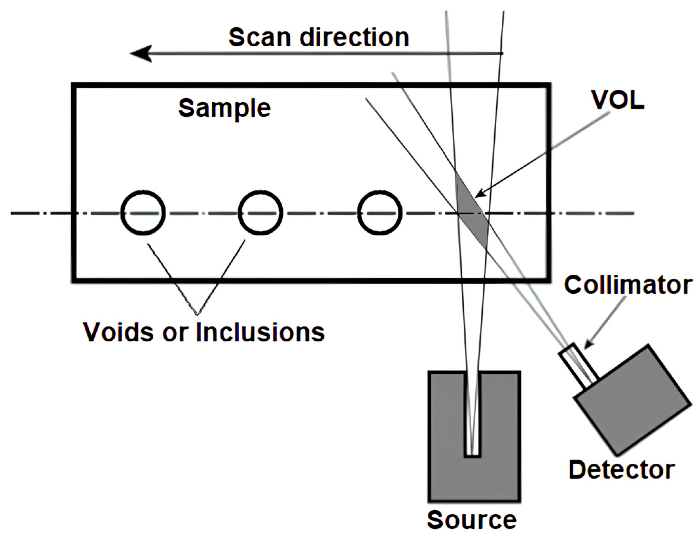
Figure 1. Schematic representation of Compton backscattering geometry.
Atoms 13 00067 g001
Figure 2. The top view of the column. The concrete (light gray), rebar (red), and crushed stone (dark gray). Units in centimeters.
Atoms 13 00067 g002
Figure 3. Incidence locations of the photon beam corresponding to each scan point on the sample.
Atoms 13 00067 g003
Figure 4. Examples of the photon fluence distribution to (a) 59.51 keV (241Am) and (b) 1170 keV (6°Co), for the central incidence of the beam (at coordinate x = 0 cm).
Atoms 13 00067 g004
Figure 5. Backscattered photon counts as a function of the incident beam’s scanning position. (a) 241Am and (b) 60Co.
Atoms 13 00067 g005
Table 1. Chemical composition of basaltic gravel.
Oxid.SiO2Fe2O3Al2O3CaOMgONa2O3TiO2K2OP2O5MnOSrOZnOZrO2
%50.515.514.210.04.12.51.31.00.30.20.10.10.1
Table 2. Density Contrast values associated with the different constituent materials of the sample.
Density Contrast (%)
241Am60Co
Cement/Aggregate6.313.31
Aggregate/Steel Rebar20.0220.13
Disclaimer/Publisher’s Note: The statements, opinions and data contained in all publications are solely those of the individual author(s) and contributor(s) and not of MDPI and/or the editor(s). MDPI and/or the editor(s) disclaim responsibility for any injury to people or property resulting from any ideas, methods, instructions or products referred to in the content.