Article

Elastic e-Atom Scattering Using Multi-Configuration Dirac–Fock Partial Wave Analysis

Department of Physics, Indian Institute of Technology Patna, Bihta 801103, India
*
Author to whom correspondence should be addressed.
Atoms 2025, 13(5), 39; https://doi.org/10.3390/atoms13050039
Submission received: 22 February 2025 / Revised: 18 April 2025 / Accepted: 27 April 2025 / Published: 30 April 2025

Abstract

:
A novel scattering formalism, the multi-configuration Dirac–Fock partial wave analysis (MCDF-PWA), is presented in this study. This approach extends the conventional Dirac partial wave analysis by incorporating multiple atomic configurations of the target scatterer. The newly formulated methodology is employed to compute the cross-sections in elastic e-atom scattering. The analysis is performed for a few atomic targets like Mg, Ca, and Ba.

1. Introduction

Scattering is a fundamental process that describes how particles, such as electrons, protons, neutrons, etc., interact with target systems -such as atoms, ions, or molecules. By analyzing the projectile–target interaction, scattering processes provide valuable insights into the structural and dynamic properties of the target system. For instance, the foundational understanding of atomic nuclei and their properties was derived from experiments conducted in the early 1900s by Ernest Rutherford, along with their assistants H. Geiger and E. Marsden [1]. Building on their success, numerous experiments were subsequently conducted, providing valuable insights into the properties of atoms and molecules [2]. For example, in 1914, Frank and Hertz showed that electron scattering can be used in spectroscopic studies, revealing important information about energy levels and transition states in atoms [3]. Their pioneering work validated the Bohr theory of discrete energy levels in atoms.
The development of scattering theory goes back to the early 1930s [4,5]. Since then, it has progressed significantly, both theoretically and experimentally. Significant breakthroughs in atomic and molecular physics were made concurrently with the development of quantum physics. The concept of the wave–particle duality of matter cleared the comprehension and acceptance of the uncertainty limits of the measuring process. This radical idea suggested a critical limit to the accuracy that can be achieved in experiments, the limit that emerges from the behavior of particles in the quantum domain. The advances made in the field of quantum physics also helped the development of quantum technology [6]. These developments made further probing and understanding of the micro world possible.
Some of the important parameters analyzed in scattering studies are the scattering phase shift ( δ ), differential cross-section (DCS), total cross-section (TCS), time delay, etc. The scattering phase shift ( δ ) is the fundamental quantity that describes how the presence of a scattering potential (the target atom) modifies the wavefunction of an incoming projectile. Note that δ is the “real” scattering phase shift in elastic scattering. However, when the incident projectile energy exceeds the first excitation threshold, inelastic scattering channels must be included for an accurate description of the scattering process [7]. In a theoretical formulation, these inelastic scattering channels can be accounted for by using a complex absorption potential. This results in complex scattering phase shifts [7,8]. The DCS is defined as the number of particles scattered in a given direction per unit solid angle ( d Ω ) [8,9]. The TCS gives the effective area of the target that interacts with the incoming projectile [8,9]. A comparison of theoretical cross-sectional data with experiment measurements is a critical test for the accuracy of the interaction potential form used in the theoretical model. Such comparisons help refine theoretical modeling to obtain better agreement between experiments and theory, leading to a more accurate understanding of the underlying physics. A significant challenge in the experimental DCS measurement in the earlier days was quantifying the entire scattering range from 0 ° to 180 ° . But, with the development of techniques such as the magnetic angle-changing method [10,11], the experimental measurement of the complete scattering cross-section range became possible.
The basic idea in scattering studies is to consider single particle collisions between the projectile and the target. A multi-configurational treatment of the atomic target is required because their ground state cannot be accurately defined with a single configuration. This reasoning necessitates a multi-configurational treatment, which includes the multiple configurations of the scatterer in the initial state. Similarly, the final state correlation effects can be included by writing the outgoing electron as a linear combination of scattering from each of the individual configurations considered. Thus, within the partial wave formalism [8,12], the cross-section calculation has to be modified to include the contributions from multiple atomic configurations. Hence, the present study extends the Dirac partial wave analysis to include multi-configurational initial state in its formulation. This approach is particularly valid for atomic systems where the first excited state energy level is very close to the ground state energy level, such as in alkali and alkaline earth atoms. So, in this work, we considered a few alkali earth atoms (Mg, Ca, and Ba) and conducted the cross-section analysis. Accurate cross-section data for electron scattering from neutral atoms and ions are crucial for various applications, including thermonuclear fusion and plasma diagnostics in astrophysics [13,14]. In addition, elastic electron scattering data plays importance in modeling various phenomena such as galaxy evolution, interstellar clouds, and biophysical studies of metabolic processes [15,16,17].
In the present study, we investigated electron elastic scattering from Mg, Ca, and Ba atoms. The extensive cross-section database (refer to [18,19] and references therein) provided a valuable resource for verifying the cross-sections computed for these atomic targets. Our analysis focuses on low projectile energies, where the initial state correlation effects are more significant. For comparison, we primarily rely on experimental data, supplemented by a few theoretical calculations. For Mg, the experimental results by Predojević et al. [20] and Williams and Trajmar [21] are considered. Additionally, for the comparison of theoretical cross-sections, we selected calculations by Zatsarinny et al. [22] using the B-spline R-matrix (BSR) method. Milisavljević et al. [23] carried out both experimental and theoretical studies of e-Ca scattering for energies 10 eV, 20 eV, 40 eV, 60 eV, and 100 eV. In their work, theoretical calculation was performed using non-relativistic Hartree–Fock core-polarization potential (HFCP) method. Theoretical calculations by S. Bharti et al. [24] using the relativistic coupled-cluster singles and doubles partial wave analysis (RCCSD-PWA) method was also considered for Ca cross-section comparison. In addition, theoretical results using Quasi relativistic Hartree-Fock (QRHF) and Hartree-Fock (HF) methods by J. Yuan [25] in the very low-energy range are considered for cross-section comparison from Ca and Ba. For Ba, calculations using the Convergent Close-Coupling (CCC) scheme with 115 states (CCC(115)) by Fursa et al. [26] were also considered. Jensen et al. [27] investigated experimental elastic scattering from Ba atoms at incident energies of 20 eV, 30 eV, 40 eV, 60 eV, 80 eV, and 100 eV. Furthermore, Wang et al. [28] studied experimental e-Ba elastic scattering at 15 eV and 20 eV.
Section 2 outlines the theoretical approach adopted in this study, followed by Section 3, which presents the results and discussion. Finally, a brief conclusion is provided in Section 4.

2. Theory

The current work focuses on extending the relativistic partial wave analysis to take into account the target scatterer’s multiple atomic configurations in the initial state. Attention is given to elastic e-atom scattering with cross-section as the prime parameter analyzed. Section 2.1 describes the atomic potential model used in the study, and Section 2.2 explains the formulation of multi-configuration Dirac–Fock partial wave analysis (MCDF-PWA).

2.1. Potential Details

Formulating an appropriate interaction potential to represent the e-atom/molecule scattering is a key aspect in the collision study. In the present e-atom scattering analysis, the interaction potential is formulated using the well-established optical model potential [29]:
V ( r ) = V s t ( r ) + V e x ( r ) + V c p ( r ) + i V a b s ( r ) .
Here, V s t , V e x , and V c p represent the static, exchange interaction, and correlation–polarization potentials, respectively. A complex absorption potential, V a b s , is also used to account for the possible inelastic scattering channels. The static potential, V s t , represents the combined effect of the electrostatic potential from the electron cloud and the point nuclear potential model considered. Its form at a general point r can be calculated as:
V s t ( r ) = Z e 2 r e r 0 r 4 π ρ e ( r ) r 2 d r + r 4 π ρ e ( r ) r d r ,
where ρ e ( r ) is the electron charge density and Z is the atomic number of the atom under consideration.
In e-atom collisions, it is essential to consider the possibility of rearrangement collisions, where the incoming projectile exchanges positions with the atomic electrons. Here, we adopted the exchange potential formulation proposed by Furness and McCarthy [30]. The exchange potential form used, V e x , is obtained directly from the formal expression of the non-local exchange interaction by applying a WKB-like approximation to the wave functions [29]:
V e x ( r ) = 1 2 [ E V s t ( r ) ] 1 2 ( E V s t ( r ) ) 2 + 4 π a 0 e 4 ρ e ( r ) 1 / 2 .
Here, E represents the impact energy of the incident electron, and a 0 is the Bohr radius. Bransden et al. [31] used the suggested exchange potential to study electron scattering from hydrogen and helium atoms, and concluded that it accurately described exchange effects, thus justifying its use in the present calculation.
When the projectile electron interacts with the target atom, the electric field of the incoming electron can distort the atomic electron cloud, necessitating the inclusion of a polarization potential. In addition, correlation effects also need to be included. We discuss the formulation of correlation–polarization potential, V c p , below using V p o l and V c o which are the polarization and correlation potentials, respectively. In the present study, the Buckingham polarization potential is used to model the long-range polarization interaction. It is defined as [7,29]:
V p o l ( r ) = α d e 2 2 r 2 + d 2 2 .
Here, α d denotes the dipole polarizability of the target atom [32], and d is the cut-off parameter introduced to prevent divergence at r = 0 . The corresponding α d values for Mg, Ca, and Ba are 1.01 × 10 23 cm 3 , 2.28 × 10 23 cm 3 , and 3.97 × 10 23 cm 3 , respectively, [32]. The α d values are obtained from experimental data [32]. The cut-off parameter, d, can be expressed as [33]:
d 4 = 1 2 α d a 0 Z 1 / 3 b p o l 2 ( E ) ,
where Z is the atomic number of the target atom. In the theoretical works of S. Seltzer [33], the value of b p o l is suitably adjusted to agree with the experimental DCS data at small scattering angles for noble gases and mercury; the same formalism is adopted for other atoms as well [29]. The specific form of the energy-dependent adjustable parameter b p o l used is [29,33]:
b p o l 2 ( E ) = m a x { ( E 50 eV ) / ( 16 eV ) , 1 } .
Additionally, to account for more complex interactions, such as the mutual repulsion between electrons, a correlation potential, V c o , is also required. The correlation potential form used in the present study is derived within local-density approximation (LDA) under the assumption that the projectile at position r experiences the same correlation energy as it would if moving in a free electron gas with a density equal to the local atomic electron density, ρ e ( r ) [29]. A density parameter r s is introduced in order to define correlation potential, V c o , which takes the form [29]:
r s 1 a 0 3 4 π ρ e ( r ) 1 / 3 .
The parameter r s , expressed in Bohr radius, a o , represents the sphere’s radius that, on average, contains one electron of the gas. As suggested in the work of Perdew and Zunger, when electrons are used as projectiles, the correlation potential can be parametrized as [34]:
V c o ( r ) = e 2 a 0 ( 0.0311 ln ( r s ) 0.0584 + 0.00133 r s ln ( r s ) 0.0084 r s ) , for r s < 1 , e 2 a 0 β 0 1 + ( 7 / 6 ) β 1 r s 1 / 2 + ( 4 / 3 ) β 2 r s ( 1 + β 1 r s 1 / 2 + β 2 r s ) 2 , for r s 1 ,
where β 0 = 0.1423, β 1 = 1.0529, and β 2 = 0.3334. The correlation-–polarization potential, V c p , which combines the Buckingham polarization potential (Equation (4)) with the correlation potential (Equation (8)), is expressed as [29]:
V c p ( r ) = m a x [ V c o ( r ) , V p o l ( r ) ] i f r < r c p , V p o l ( r ) i f r r c p ,
where r c p is taken as the outer radius at which correlation potential, V c o , and polarization potential, V p o l , cross.
To accurately define the interaction potential form, it is essential to account for the possibility of loss of flux from the elastic scattering channel due to transitions into inelastic channels. In this study, we employ the absorption potential form proposed by Salvat [33], which is given by:
V a b s ( r ) = 2 ( E L + m e c 2 ) 2 m e c 2 ( E L + 2 m e c 2 ) × A a b s 2 [ ν L ρ e ( r ) σ b c ( E L , ρ e , Δ ) ] .
Here, m e is the electron mass. For an incident projectile energy E, the local kinetic energy E L is expressed as E L ( r ) = E V s t ( r ) V e x ( r ) . The local velocity, ν L , given by ν L = ( 2 E L / m e ) 1 / 2 describes the interaction of the projectile as if it were moving within a homogeneous gas of electron density ρ e ( r ) . The term σ b c ( E L , ρ e , Δ ) represents the cross-section for collisions where the energy transfer exceeds the energy gap Δ (the first excitation energy of the atom considered). Finally, the empirical parameter A a b s is set to 2, as suggested in the works of Salvat [33]. For electron scattering, inelastic channels are open only when the energy of the projectile is larger than the first excitation threshold Δ [33].
In the present study, electron densities are computed using multi-configuration Dirac–Fock (MCDF) [35] and single-configuration Dirac–Fock (DF) [36] formalisms. In the MCDF approach, the initial state wave function Ψ , is expressed as linear combinations of configuration state functions (CSFs), Φ i [35]:
Ψ = i C i Φ i ,
where Φ i are Slater determinants built from Dirac spinors and C i are configuration mixing coefficients, determined by solving the relativistic configuration interaction (RCI) equations. These coefficients are normalized such that:
i | C i | 2 = 1
These CSFs are constructed from the anti-symmetric products of Dirac one-electron orbitals, ensuring that the total wavefunction satisfies the Pauli exclusion principle while incorporating relativistic effects. Using the GRASP92 package [37], the MCDF and DF electron densities of free atomic targets are calculated. The optimized level (OL) calculations are performed for MCDF targets using the GRASP92 package.

2.2. Multi-Configuration Dirac–Fock Partial Wave Analysis

The optical model potential, V ( r ) (from Equation (1)), is used to represent e-atom interaction. In this study, the scattering parameters are computed using relativistic partial wave formalism [12]. To implement the Dirac partial wave analysis for calculating the scattering parameters, the ELSEPA package [29] is used. For a given interaction potential, V ( r ) , the Dirac equation describing e-atom scattering is [38]:
c α . p + β m e c 2 + V ( r ) Ψ E κ m ( r ) = E Ψ E κ m ( r ) .
Here, p = k is the momentum vector for a given relativistic wave number k of the projectile electron. α and β are the 4 × 4 Dirac matrices and c is the speed of the light in vacuum. The relativistic quantum number, κ , is defined using orbital angular momentum quantum number, , and total angular momentum quantum number, j, as κ = ( j ) ( 2 j + 1 ) . The relativistic wave function Ψ E κ m is labeled by E, κ , and magnetic quantum number m. It can be resolved into radial and angular components as [38]:
Ψ E κ m = 1 r P E κ ( r ) Ω κ , m ( r ^ ) i Q E κ ( r ) Ω κ , m ( r ^ ) ,
where P E κ ( r ) and Q E κ ( r ) are, respectively, the large and small component of the radial wave function and Ω κ , m ( r ^ ) are the spherical spinors which represent the angular part. P E κ ( r ) in the asymptotic region can be approximated as:
P E κ ( r ) s i n k r π 2 + δ κ .
Here δ κ represents the scattering phase shift which contains all the information of the e-atom interactions. The relativistic phase shift, δ κ , contains two parts: spin-up component δ + = δ κ = 1 and spin-down component δ = δ κ = . The phase shift is obtained from the radial wave functions which are solved by power series method using the subroutine package RADIAL [39]. From the scattering phase shift, scattering amplitudes: direct, f ( k , θ ) and spin-flip, g ( k , θ ) , scattering amplitudes are obtained. It takes the form [40]:
f ( k , θ ) = 1 2 i k = 0 { ( + 1 ) [ e x p ( 2 i δ + ) 1 ] + [ e x p ( 2 i δ ) 1 ] } P ( c o s θ ) ,
and
g ( k , θ ) = 1 2 i k = 0 { e x p ( 2 i δ ) e x p ( 2 i δ + ) } P 1 ( c o s θ ) ,
where P ( c o s θ ) and P 1 ( c o s θ ) denote Legendre polynomial and associated Legendre polynomial of order . The DCS can be obtained using the above scattering amplitude expression as [12,40]:
d σ d Ω = | f ( k , θ ) | 2 + | g ( k , θ ) | 2 .
For an accurate theoretical representation, it is essential to include multiple atomic configurations to represent the initial state of the target. In the newly proposed formulation-MCDF-PWA, the initial state is modeled as a superposition of ground and excited configurations of the target atom having the same J and parity value. From each of these atomic configurations, individual interaction with the projectile is considered. This means that the possibility of electron scattering from each of the atomic configurations is accounted for while calculating the scattered electron wavefunction. To incorporate these multiple configurations in the calculation, we extend the well-established Dirac partial wave analysis to include both ground and excited states in the calculation. For a given incident energy E, the scattered wave function Ψ E κ m (from Equation (13)) can be expressed as a weighted sum of the scattering contributions from multiple configurations:
Ψ E κ m = i C i Ψ E κ i m i
where Ψ E κ i m i represents the scattering wave function associated with the i-th configuration (ground or excited states) and C i denotes the configuration weight corresponding to the fractional contribution from each atomic state wave function. The quantity | C i | 2 represents the CSF weight for a specific atomic configuration, as given in Equation (11). Note that the C i ’s are the same coefficient used to represent the initial state. In this approach, one reasonably approximate that the scattered electrons from each atomic configurations is also weighted by the same factor as in the initial state. The resulting scattering amplitudes obtained after interaction with each configuration are then weighted by the corresponding configuration weight factor ( C i ). Specifically, by substituting the modified radial solution (from Equation (19)) into the Dirac Equation (Equation (13)) and solving the direct and spin-flip scattering amplitudes from Equations (16) and (17) is modified as follows:
f ˜ ( k , θ ) = i C i f i ( k , θ ) ,
and
g ˜ ( k , θ ) = i C i g i ( k , θ ) .
Using the modified scattering amplitudes, the DCS changes as:
d σ d Ω = | f ˜ ( k , θ ) | 2 + | g ˜ ( k , θ ) | 2 = | i C i f i ( k , θ ) | 2 + | i C i g i ( k , θ ) | 2 .
Detailed derivations of the MCDF partial wave equations are given in the Appendix A. The modified DCS expression explicitly represents the coupling between scattering from the target atom’s different configurations. In this study, the cross-section computed using partial wave analysis by including multiple atomic configurations (MCDF density method), as described by Equation (22), is labeled as MCDF-PWA and those from a single atomic configuration (DF density method), as given by Equation (18), is labeled as DF-PWA in the upcoming section. Using the DCS, the integrated elastic cross-sections (ICS) can be written as [12]:
σ I C S = d σ d Ω d Ω = 2 π 0 π d σ d Ω s i n θ d θ .

3. Results

In this study, cross-sectional analyses using MCDF-PWA and DF-PWA methods are conducted, focusing on alkali earth atoms-Mg, Ca, and Ba, as scattering targets. As previously discussed, the MCDF-PWA methodology is particularly well suited for atomic systems where the energy separation between the ground state and the first excited state is relatively small. The ample availability of experimental [20,21,23,27,28] and other theoretical [22,23,24,25,26,27] case studies further supports the selection of these atomic targets. For comparison, cross-section calculations using the DF-PWA method is also performed. Section 3.1 presents the cross-sectional analysis from the multi-configurational initial states of the atomic targets with J = 0 and even parity. Section 3.2 extends the cross-section analysis where atoms are modeled in the excited states ( J = 1 ).

3.1. Electron Scattering from Multi-Configurational Initial States

Alkali earth atoms have two valence electrons in the ground-state configuration, which are occupied in the ns-subshell (n is the principal quantum number). In the proposed MCDF-PWA methodology, the formulation of the target atom’s initial state wavefunction includes not only the ns-subshell configuration but also contributions from higher orbitals, such as np and nd. For example, the ground state configuration of Mg is [ N e ] 3 s 1 / 2 2 . Under the j-j coupling scheme, this configuration exhibits even parity and J value of 0 (i.e., J = 0 + ). In the MCDF initial state, along with the [ N e ] 3 s 1 / 2 2 additional configurations [ N e ] 3 p 1 / 2 2 , [ N e ] 3 p 3 / 2 2 , [ N e ] 4 s 1 / 2 2 , and [ N e ] 3 d 3 / 2 2 are included. All these additional configurations satisfy the J = 0 and even parity conditions, same as that of the ground state of the Mg-atom. Therefore, it is valid to adopt this extended approach to include additional configurations satisfying the J = 0 + condition for a more realistic representation of the initial state of the target atom. The total ground state energy obtained from the DF calculation is −5440.51 eV and that from MCDF calculation is −5441.46 eV. Due to the inclusion of correlations, the total energy is altered in the MCDF model. This energy difference highlights the impact of correlation on the atomic structure. In the MCDF calculations, the configurations considered, and the corresponding configuration weights, C i , are given in Table 1.
The probability conservation validates the condition that for a given J, the total weights of CSFs sum to unity. The condition i | C i | 2 = 1 must always be satisfied. Hence, configuration weights, C i , can take both positive and negative values. Table 1 shows that the [ N e ] 3 s 1 / 2 2 configuration has the highest C i value, contributing 0.9629 to the total wave function. This is followed by [ N e ] 3 p 3 / 2 2 and [ N e ] 3 p 1 / 2 2 configurations with contributions of 0.2185 and 0.1511, respectively. The C i values are small and negative, for [ N e ] 4 s 1 / 2 2 and [ N e ] 3 d 3 / 2 2 configurations with values of −0.0425 and −0.0194, respectively. The analysis is limited to five doubly occupied valence configurations listed in Table 1, as the contributions from other higher configurations were negligible. Hence, only 5 doubly occupied configurations (
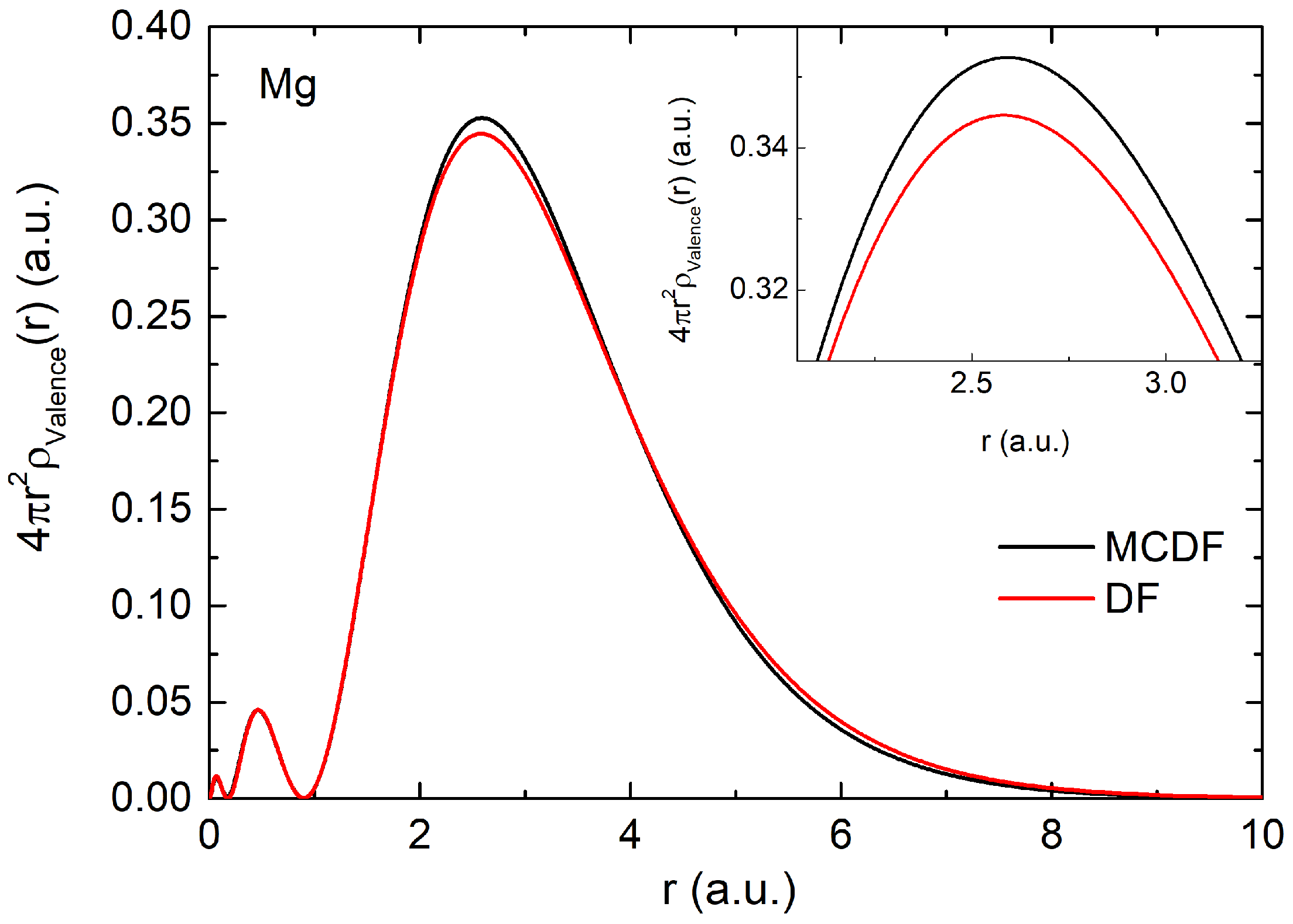
Table 1) are considered in the present analysis. The respective atomic densities are calculated for each of the configurations considered and Figure 1 shows the electronic density of valence orbitals in the DF ( 3 s 1 / 2 2 ) and MCDF ( | C 1 | 2 3 s 1 / 2 2 + | C 2 | 2 3 p 1 / 2 2 + | C 3 | 2 3 p 3 / 2 2 + | C 4 | 2 4 s 2 + | C 5 | 2 3 d 3 / 2 2 ) approaches. Note that the difference due to the initial state correlation effect is incremental on the electronic density. This means that the changes in the scattering dynamics are expected to be less significant in the high energies. However, for low energies, the difference is expected to be significant as the projectile electron spends a larger amount of time near the target’s vicinity in the low-energy cases. Hence, the focus is on low-energy scattering in the present study.
Scattering amplitudes are determined using each atomic density obtained, and the cross-section in the MCDF-PWA method is computed by weighting the scattering amplitudes of each configuration with their respective configuration weights, C i values, as described using Equations (11) and (19). The DCS calculation using MCDF-PWA methodology is performed for a few sets of incident energies (20 eV, 10 eV, 0.1 eV, and 0.05 eV), and the results are presented in Figure 2. For comparison, the DF-PWA results are also plotted to highlight the differences and validate the extended multi-configurational approach. In the DF case, the configuration of Mg is considered in its ground state: [ N e ] 3 s 1 / 2 2 . Figure 2 shows that the DCSs using the MCDF-PWA and DF-PWA methods have similar qualitative behavior; however, they are a little different in magnitude.
In the low-energy range for e-Mg elastic scattering, as mentioned earlier, experimental results are available from the works of Predojevi’c et al. [20] and Williams and Trajmar [21]. For theoretical cross-section comparison, we used the results by Zatsarinny et al. [22] obtained using the BSR method. In Figure 2a, for incident energy 20 eV, the MCDF-PWA data shows good agreement with the experimental results of Williams and Trajmar [21] in the low- and mid-scattering angle range. At 120 ° and 150 ° , the MCDF-PWA near the minimum has a good quantitative agreement with the experimental results of Predojevi et al. [20]. As expected, the DF-PWA results closely align with the MCDF-PWA since the 3 s subshell contributes significantly to the overall cross-section. However, the MCDF-PWA shows an increased cross-section magnitude compared to the DF-PWA due to the inclusion of additional configurations with J = 0 + considered in the MCDF-PWA calculations.The MCDF-PWA aligns qualitatively well with the experimental data of Predojevi et al. [20]. The theoretical calculations using the BSR method [22] show agreement with the MCDF-PWA and DF-PWA results but deviate from experimental data at around 50 ° . For 10 eV incident energy, in Figure 2b, both the MCDF-PWA and DF-PWA data have good agreement with experimental results [20,21] in the low scattering angle range. However, a slightly better agreement is noted in this range for DF-PWA over MCDF-PWA. In the mid-angle range, MCDF-PWA shows strong consistency with the experimental data of Williams and Trajmar [21], but only a qualitative agreement is noted with the experimental results of Predojevi’c et al. [20]. Here also, the cross-section using BSR method [22] has an off behavior at around 60 ° when compared with the experimental results [20,21]. The current analysis is also extended to very low-energy ranges. With 0.1 eV in Figure 2c and 0.05 eV in Figure 2d, both MCDF-PWA and DF-PWA exhibit a similar qualitative behavior in the cross-section. However, the MCDF-PWA results consistently show higher cross-section magnitudes compared to the DF-PWA data. As discussed earlier, this increase is attributed to the inclusion of multiple initial-states in the MCDF-PWA calculations.
The ground state configuration of Ca is [ A r ] 4 s 1 / 2 2 , where 4 s is the valence subshell. This state alone is considered in the DF density formulation. For MCDF analysis, in addition to [ A r ] 4 s 1 / 2 2 configuration, additional adjacent configurations [ A r ] 3 d 3 / 2 2 , [ A r ] 3 d 5 / 2 2 , [ A r ] 4 p 1 / 2 2 and [ A r ] 4 p 3 / 2 2 are also considered. The configurations and their respective C i values are provided in Table 2. Here, as expected, a maximum configuration weightage of 0.9581 is noted for [ A r ] 4 s 1 / 2 2 configuration, followed by [ A r ] 4 p 3 / 2 2 and [ A r ] 4 p 1 / 2 2 configurations with values 0.2283 and 0.1633, respectively. The contributions from [ A r ] 3 d 5 / 2 2 and [ A r ] 3 d 3 / 2 2 are small and negative, with values −0.0438 and −0.0354, respectively. 
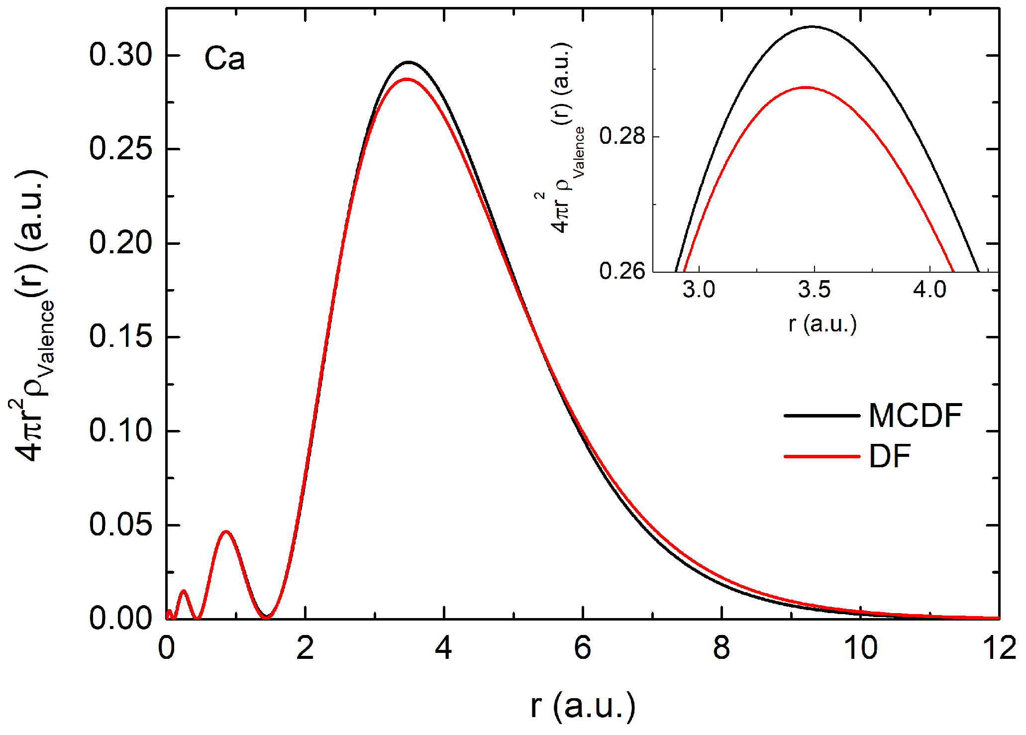
Figure 3 shows the electron density of valence orbitals using the MCDF ( | C 1 | 2 4 s 1 / 2 2 + | C 2 | 2 3 d 3 / 2 2 + | C 3 | 2 3 d 5 / 2 2 + | C 4 | 2 4 p 1 / 2 2 + | C 5 | 2 4 p 3 / 2 2 ) and DF ( 4 s 1 / 2 2 ) methods. The MCDF valence density is slightly higher than the DF valence density. This increase arises due to the contributions from additional configurations, which are considered in the MCDF approach but absent in the DF method. The ground state total energy obtained from DF and MCDF calculations are −18,495.86 eV and −18,496.42 eV, respectively.
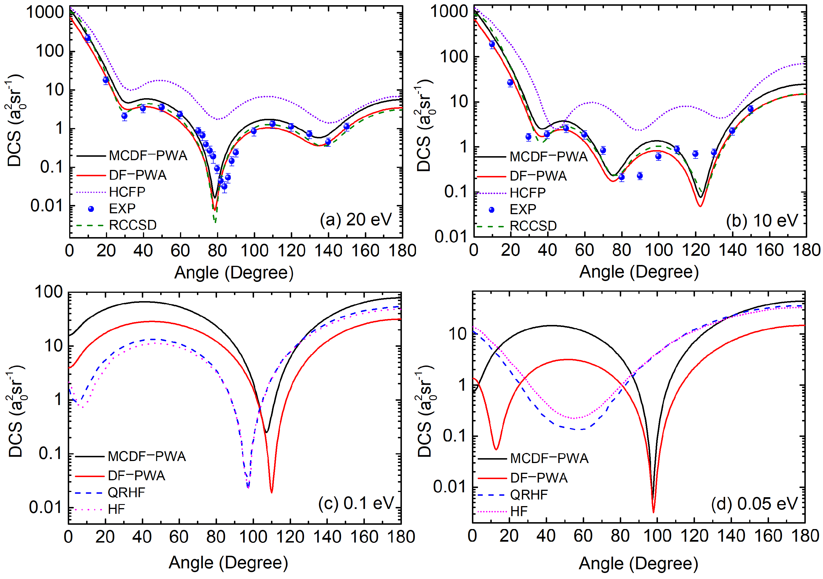
Figure 4 depicts the e-Ca cross-section using MCDF-PWA and DF-PWA methods for the energies 20 eV, 10 eV, 0.1 eV, and 0.05 eV. For 20 eV and 10 eV energies, experimental results by Milisavljević et al. [23] are available. Also, for the considered energies comparisons using HFCP [23] and RCCSD-PWA [24] are also employed. In Figure 4a for 20 eV, the MCDF-PWA results show good agreement with experiment data [23] in the forward scattering angle range. A significant quantitative improvement is observed in the cross-section dip at 80 ° when using MCDF-PWA over DF-PWA approaches. Although the MCDF-PWA data slightly deviate from the experimental data in this angular range, it still demonstrates strong quantitative agreement. Also, in this range, MCDF-PWA results have a greater agreement than the highly sophisticated RCCSD-PWA method [24]. In the high-angle range, the MCDF-PWA continues to align well with the experimental data, while the HFCP theoretical results deviate considerably, showing behavior far off from the experimental observations. In Figure 4b for 10 eV, the cross-section results from both MCDF-PWA and DF-PWA methods show good agreement with the experimental data [23], with the DF-PWA exhibiting a slightly better match than MCDF-PWA. In the angle range of 40 ° 140 ° , MCDF-PWA has a better alignment with the experimental results, with the cross-section curve passing through some of the experiment data points. The present MCDF-PWA results also agree with the RCCSD-PWA calculations [24], further solidifying the new formalism. However, a larger disagreement is noted with the HFCP results [23]. No experimental data are available for comparison in the very low-energy range (for 0.1 eV and 0.05 eV case studies). However, theoretical results by J. Yuan [25] using QRHF and HF methods are available. For 0.1 eV (Figure 4c), both MCDF-PWA and DF-PWA exhibit a single dip in the cross-section at around 110 ° , whereas the QRHF and HF results show a dip at 100 ° . Similarly, for 0.05 eV (Figure 4d), the cross-section dip in the QRHF and HF results appears shifted to the left compared to the MCDF-PWA and DF-PWA calculations. Notably, the MCDF-PWA shows a higher cross-section magnitude compared with DF-PWA. Also, the cross-section computed using both methods has a dip at around 100 ° . Additionally, a second dip in the DF-PWA is noted at around 10 ° , which is absent in MCDF-PWA. The present very low-energy analysis shows that the MCDF-PWA results produces qualitative differences compared to the DF-PWA calculations.
The ground state configuration of Ba is [ X e ] 6 s 1 / 2 2 , with 6 s being the valence subshell. Only this configuration is considered in the DF density formulation. In the MCDF analysis, additional configurations [ X e ] 4 f 5 / 2 2 , [ X e ] 4 f 7 / 2 2 , [ X e ] 5 d 3 / 2 2 and [ X e ] 5 d 5 / 2 2 are considered. These configurations also satisfy the J = 0 + condition. The C i values for each of the configurations considered are detailed in Table 3. The dominant contribution to the initial state wave function comes from the [ X e ] 6 s 1 / 2 2 configuration, with a C i value of 0.9789. From Table 3, it is noted that the contributions from all other considered configurations are small compared to the 6 s subshell. The second largest contribution to the wave function arises from [ X e ] 5 d 5 / 2 2 configuration, with a weight of −0.1572, followed by [ X e ] 5 d 3 / 2 2 configuration with −0.1287 contribution. The least contributions are from [ X e ] 4 f 7 / 2 2 and [ X e ] 4 f 5 / 2 2 configurations with C i values 0.0146 and 0.0126, respectively. 
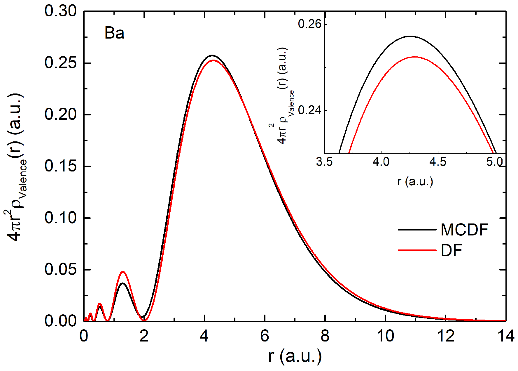
Figure 5 presents the valence shell electron density computed using both the DF ( 6 s 1 / 2 2 ) and MCDF ( | C 1 | 2 6 s 1 / 2 2 + | C 2 | 2 4 f 5 / 2 2 + | C 3 | 2 4 f 7 / 2 2 + | C 4 | 2 5 d 3 / 2 2 + | C 5 | 2 5 d 5 / 2 2 ) approaches. A prominent density peak is observed at around 4 a.u., with the MCDF valence density exhibiting a higher magnitude compared with the valence DF density. Here, the ground-state total energy obtained from DF and MCDF calculations are, respectively, −221,382.26 eV and −221,382.69 eV.
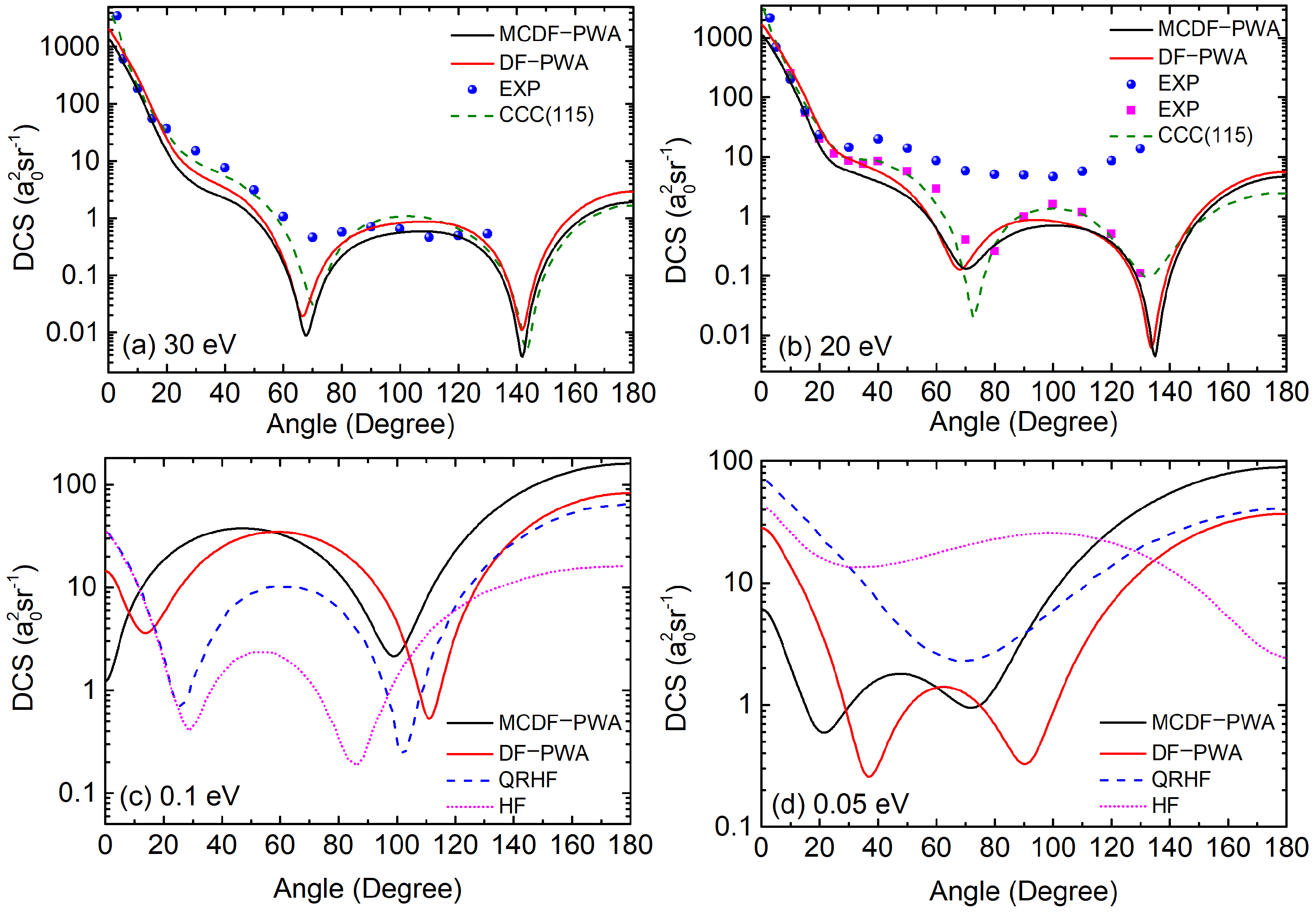
Analysis using MCDF-PWA and DF-PWA methodologies for a few low and very low incident energy cases (30 eV, 20 eV, 0.1 eV, and 0.05 eV) are presented in Figure 6. For 30 eV and 20 eV, experimental results by Jensen et al. [27] are available. The theoretical cross-section comparison at 30 eV and 20 eV, is performed using CCC(115) results [26] and for energies of 0.1 eV and 0.05 eV using QRHF and HF methods [25]. At an incident energy of 30 eV (Figure 6a), the MCDF-PWA results show excellent agreement with the experimental data in the forward scattering region. Compared to DF-PWA, MCDF-PWA yields slightly lower cross-section values, primarily due to the configurational coupling effects and the negative C i coefficients associated with the configurations [ X e ] 5 d 5 / 2 2 and [ X e ] 5 d 3 / 2 2 , as detailed in Table 3. These negative contributions reduce the dominant influence of the 6 s subshell, reducing the overall cross-section magnitude for MCDF-PWA. Moreover, both DF-PWA and MCDF-PWA closely align with the CCC(115) results, further validating the accuracy of the present analysis. Similarly, for the 20 eV (Figure 6b), the MCDF-PWA demonstrates good agreement with the experimental results of Jensen et al. [27] in the forward scattering region. However, at higher scattering angles, a notable deviation from the experimental data [27] is observed. In comparison with the experimental results of Wang et al. [28], the MCDF-PWA exhibits good qualitative agreement. Additionally, a comparable level of agreement is noted between MCDF-PWA and CCC(115) results [26]. For very low-energy cases, at 0.1 eV (Figure 6c), the MCDF-PWA shows a single dip, whereas the results from DF-PWA, QRHF, and HF methods exhibit two dips in the cross-section. At an incident energy 0.05 eV (Figure 6d), both MCDF-PWA and DF-PWA exhibit two dips in the cross-section. The MCDF-PWA dips appear at approximately 20 ° and 70 ° , while the DF-PWA exhibits lower magnitudes with right-shifted dips at around 40 ° and 90 ° . The QRHF cross-section features a single dip at around 70 ° , whereas the HF cross-section does not show any sharp dips.
In addition to DCS analysis using MCDF-PWA and DF-PWA methods, the present study also performed calculations to obtain the ICS (using Equation (23)) for all atomic cases. Table 4 presents a comparison of the ICS results in the low-energy range for Mg, Ca, and Ba, obtained using the MCDF-PWA and DF-PWA methods. A few low-energy cases are considered, and the results are compared with other existing calculations [22,24,26] and experimental results [20,23,28]. The cross-section magnitudes are observed to be larger in calculations using the MCDF-PWA compared to the DF-PWA method for Mg and Ca atoms and on the contrary in Ba. The ICS in Mg shows similar qualitative behavior in all the compared methodologies; however, quantitatively, they differ. An encouraging comparison of the MCDF-PWA and RCCSD-PWA approach [24] is seen in Ca. This shows that the current MCDF-PWA include the correlations at par with RCCSD-PWA method which is worthwhile to report. At 20 eV, the experimental results for Ca and Ba show good agreement with both the MCDF-PWA and DF-PWA methods, falling within the experimental error bars. In contrast, for Mg, the experimental data align more closely with the DF-PWA results than with those from the MCDF-PWA approach.

3.2. Electron Scattering from the Excited States

The MCDF-PWA formalism can also be applied to analyze scattering from atoms in excited states. This theoretical approach of modeling atomic samples in the excited configuration effectively demonstrate experimental scenarios where atomic samples are prepared in excited states [41,42]. Here, in the excited state scattering, the density of the target atom’s electron are calculated for the excited configurations and then the interaction potential is computed (refer Equation (1)). In the theoretical formulation of the interaction potential, we considered the absorption potential to account for the possible inelastic scattering channels (refer Section 2.1). The used absorption potential form (Equation (9)) depends on the first excitation threshold, Δ , and a global strength factor A a b s . The inelastic channels are considered only when the incident energy is greater than Δ . In scattering calculations where the atomic samples are prepared in the excited states, the Δ values are calculated from the energy difference between considered excited configuration and its nearby excited state. Note that the absorption accounts only for excitations, not for the flux loss owing to de-excitation. This omission is one of the practical limitations of this method. With the formulated interaction potential, the scattering parameters can be obtained by employing relativistic partial wave analysis (refer to Section 2.2). A key advantage of this theoretical methodology is its flexibility: it can be extended to any given J value and any spin state.
In the present e-atom cross-section analysis, alkali earth atoms are considered as the target. These atoms have close-shelled structures in the ground state, with a fully occupied valence n s -subshell. However, when considering excited-states, the closed-shell symmetry is disrupted as electrons are redistributed into higher-energy orbitals. As an example, an analysis is performed for Ba for J = 1 , with a focus given to the very low-energy limit (0.1 eV, 0.15 eV, and 0.2 eV) as the impact of configurational coupling is expected to be prominent in the very low-energy range.
For obtaining the excited states of Ba, the two valence electrons from the ground state [ X e ] 6 s 1 / 2 2 , are considered to undergo single excitation to higher adjacent subshells, specifically 6 s 1 / 2 , 4 f 5 / 2 , 5 d 3 / 2 , 5 d 5 / 2 , and 6 p 1 / 2 . The excited states that give J = 1 are listed in Table 5. In the present analysis, the only configuration that gives a convergent wavefunction in the MCDF framework are considered [35]. There are four configurations that satisfy this criterion while also producing a convergent wave function in the MCDF analysis. The considered configurations are [ X e ] 6 s 1 / 2 1 6 p 1 / 2 1 , [ X e ] 4 f 5 / 2 1 5 d 3 / 2 1 , [ X e ] 4 f 5 / 2 1 5 d 5 / 2 1 and [ X e ] 5 d 5 / 2 1 6 p 1 / 2 1 . The C i values of these states are listed in Table 5. For the DF-PWA analysis, the DF density is computed from [ X e ] 6 s 1 / 2 1 6 p 1 / 2 2 configurations. From Table 5, the highest C i of 0.9474 is associated with the configuration [ X e ] 6 s 1 / 2 1 6 p 1 / 2 1 , followed by [ X e ] 5 d 5 / 2 1 6 p 1 / 2 1 having a negative C i value of −0.3160. Among the excited states listed in Table 5, the minimum contribution to the excited state wave function are from configurations [ X e ] 4 f 5 / 2 1 5 d 3 / 2 1 and [ X e ] 4 f 5 / 2 1 5 d 5 / 2 1 
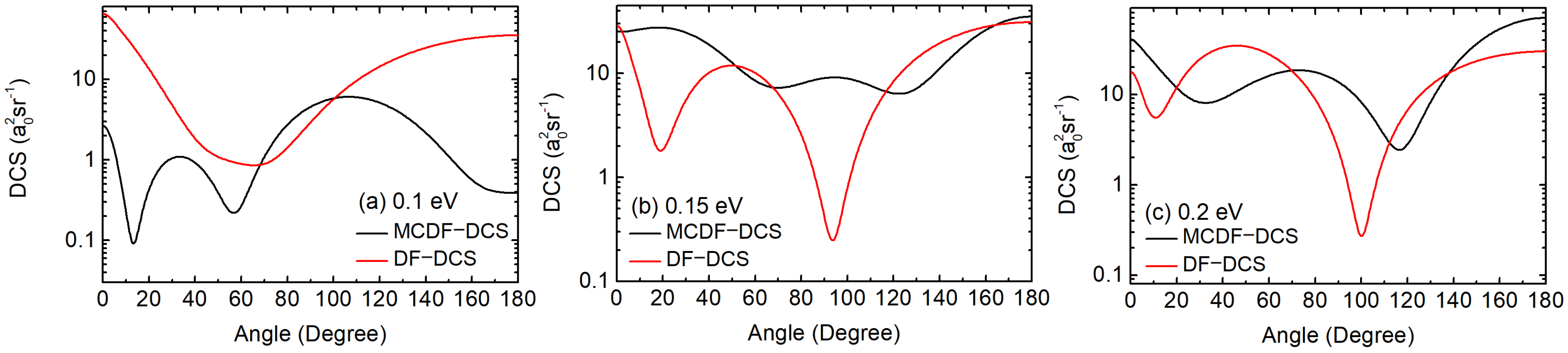
with a contribution of 0.0194 and −0.0457, respectively. Cross-section analysis using MCDF-PWA and DF-PWA methods are carried out and is shown in Figure 7. A sharp contrast in the cross-section profile between the MCDF-PWA and DF-PWA methods is observed for all the considered low-energy cases. This depicts the multi-configurational coupling effect in MCDF-PWA calculations, which is absent in DF-PWA analysis. For 0.1 eV, Figure 7a, DF-PWA exhibits a single shallow dip in the cross-section, whereas MCDF-PWA have two distinct sharp dips at approximately 10 ° and 60 ° . At 0.15 eV (Figure 7b) and 0.2 eV (Figure 7c), both DF-PWA and MCDF-PWA results display two cross-section minima. For 0.15 eV, MCDF-PWA shows dips at around 60 ° and 120 ° , while DF-PWA presents a smaller dip in the forward scattering region followed by a sharper minimum at around 90 ° . Similarly, for 0.2 eV, DF-PWA exhibits a smaller dip in the forward scattering range, followed by a sharper minimum at 100 ° . In contrast, MCDF-PWA shows a pronounced dip at 120 ° and a shallower minimum at around 30 ° .
The majority of the e-atom works have focused on elastic as well as electron-impact excitation cross-section calculations [43,44]. For instance, Wang et al. reported detailed cross-section data for electron elastic scattering, electron impact excitation, and ionization processes for boron [43] and nitrogen [44]. However, in the present study, we focused on electron scattering from atoms in an excited state, using Ba as a representative example. This study illustrates the possibility of carrying out analyses in experiments where samples are prepared in the excited state. To the best of our limited knowledge, no experimental or theoretical scattering studies have been conducted where Ba atoms are considered in the excited state alone. Thus, a direct comparison with other methods and experiments is not possible. Hence, we omit presenting the detailed analysis of the excited-state scattering of other targets and restricting only to a few energies of Ba as a specimen. A detailed analysis will follow in a subsequent communication with a robust comparison with other theoretical/experimental results wherever applicable.

4. Conclusions

For an accurate theoretical formulation, it is necessary to consider more atomic configurations to represent the initial state. The MCDF density approach is a good choice to model the atomic target considering its feasibility to include multiple atomic configurations. The Dirac partial wave analysis in the present study has been modified to incorporate the multi-configurational correlations effects. This extended approach, MCDF-PWA, allows for a more comprehensive understanding of the scattering process by considering scattering contributions from the multiple atomic configurations of the target atom. This method is particularly applicable for atomic systems where the energy gap between the ground and first excited states is small, such as in alkali and alkali earth atoms. For atomic targets, Mg, Ca, and Ba, cross-section analysis using the MCDF-PWA method is performed and discussed in detail. To contrast to the modification of the new formulation, a cross-section analysis using the simpler DF-PWA method is also carried out.
The MCDF-PWA methodology can be extended to study the scattering from the excited atoms. This flexibility enables investigating the scattering processes under more diverse conditions. However, a fundamental limitation of this approach is its inability to combine contributions from different J states, as this restriction is intrinsic to the quantum mechanical wave function. Another limitation of the new formulation is that the absorption potential form used does not account for flux loss due to possible de-excitation processes.
A significant feature of the MCDF-PWA approach is the multi-configurational coupling, which is the most prominently observed in the low-energy scattering regime, where the finer details of the interaction become more evident. This highlights the capability of the MCDF-PWA method to provide deeper insights into the scattering process compared to DF-PWA analysis. However, since no experimental cross-section results are currently available in the low-energy region, a direct comparison between theoretical calculations and experimental measurements was not feasible. This limitation highlights the need for further experimental efforts to validate and refine the theoretical models.

Author Contributions

Conceptualization, R.A. and J.J.; methodology, R.A.; software, R.A.; validation, R.A. and J.J.; formal analysis, R.A.; investigation, R.A.; resources, R.A. and J.J.; data curation, R.A.; writing—original draft preparation, R.A.; writing—review and editing, R.A. and J.J.; visualization, R.A. and J.J.; supervision, J.J.; project administration, J.J.; funding acquisition, J.J. All authors have read and agreed to the published version of the manuscript.

Funding

This research is supported by DST-SERB-CRG Project No: CRG/2022/000191, India (J.J.).

Data Availability Statement

The original contributions presented in the study are included in the article.

Conflicts of Interest

The authors declare no conflict of interest.

Appendix A

To formulate a wave equation consistent with special relativity, Dirac proposed that an electron possesses four degrees of freedom ( Ψ λ ( x , y , z , t ) , ( λ = 1 , 2 , 3 , 4 ) ) [12,38]. The MCDF method represents the N-electron wave function as a superposition of contributions from different possible atomic configurations. Building on these concepts, in the proposed MCDF-PWA methodology, for an incoming projectile traveling along the z axis and interacting with an atomic target, the asymptotic form of the scattered wave function Ψ —which consists of four components ( Ψ 1 , Ψ 2 , Ψ 3 , Ψ 4 ) —can be expressed as:
Ψ λ = a λ e i k z + i C i u λ i ( θ , ϕ ) e i k r r ( λ = 1 , 2 , 3 , 4 ) .
Here, for a given wave vector k, a λ and u λ represent the amplitude of the incident and scattered wave functions, respectively. The second term explicitly describes the scattering amplitude weighted by the mixing coefficients C i (given by Equations (11) and (19)), quantifying the scattering contribution from different atomic configurations. The DCS using this new formalism is given by:
d σ d Ω = λ = 1 4 i | C i u λ i | 2 λ = 1 4 | a λ | 2 .
Among the four-wave functions ( Ψ λ ) , Ψ 3 , and Ψ 4 dominate, making them the large components, while Ψ 1 and Ψ 2 , with lesser contributions, are the small components [12]. Hence, the DCS can be approximated as:
d σ d Ω i | C i u 3 i | 2 + | C i u 4 i | 2 | a 3 | 2 + | a 4 | 2 .
The asymptotic forms of the wave functions Ψ 3 and Ψ 4 are given by [12]:
Ψ 3 e i k z + i C i f 1 i ( θ , ϕ ) e i k r r , Ψ 4 i C i g 1 i ( θ , ϕ ) e i k r r ,
and
Ψ 3 i C i g 2 i ( θ , ϕ ) e i k r r , Ψ 3 e i k z + i C i f 2 i ( θ , ϕ ) e i k r r ,
where Equations (A4) and (A5) describe the spin-parallel and spin-antiparallel cases, respectively, relative to the incident direction. The functions f 1 , f 2 , g 1 , and g 2 are derived from the solutions obtained by Darwin [45] for the set of simultaneous differential equations that the four-wave functions, Ψ λ , satisfy [12,45].
As a case study, consider the spin parallel case (Equation (A4)). Based on the solution set proposed [45], the asymptotic forms of the wave functions ( Ψ 3 and Ψ 4 ) are given by [12]:
Ψ 3 = ( + 1 ) e i δ G + e i δ 1 G 1 i P ( c o s θ ) , Ψ 4 = e i δ G + e i δ 1 G 1 i P 1 ( c o s θ ) e i ϕ ,
where δ is the phase shift for a given t h partial wave and P ( c o s θ ) , and P 1 ( c o s θ ) are, respectively, Legendre polynomials and associated Legendre polynomials. The parameters G and G 1 are obtained from the solution set proposed by Darwin, which have the asymptotic forms [12]:
G s i n k r π 2 + δ k r , G 1 s i n k r π 2 + δ 1 k r ,
as ( + 1 ) remains fixed as 1 . Also, using the partial wave analysis, the asymptotic forms of Ψ 3 and Ψ 4 can be expanded as [12]:
Ψ 3 = 1 2 i k r i ( 2 + 1 ) [ e i ( k r π 2 ) e i ( k r π 2 ) ] P ( c o s θ ) + i C i f 1 i ( θ , ϕ ) e i k r r Ψ 4 = i C i g 1 i ( θ , ϕ ) e i k r r .
Substituting Equation (A7) in Equation (A6) and comparing the outgoing wave functions with Equation (A8), the scattering amplitude expressions are obtained. A similar set of scattering amplitudes is derived when considering the anti-parallel spin case (Equation (A5)) (for further details, see [12]). Defining the effective scattering direct and spin-flip terms, respectively, as f ˜ ( k , θ ) = i C i f i ( k , θ ) , and g ˜ ( k , θ ) = i C i g i ( k , θ ) , the scattering amplitudes can be generalized as:
direct scattering amplitude,
f ˜ ( k , θ ) = 1 2 i k = 0 { ( + 1 ) [ e 2 i δ 1 1 ] + [ e 2 i δ 1 ] } P ( c o s θ ) ,
spin-flip scattering amplitude,
g ˜ ( k , θ ) = 1 2 i k = 0 { e 2 i δ e 2 i δ 1 } P 1 ( c o s θ ) .
Using the so-obtained scattering amplitudes, the DCS can be formulated as:
d σ d Ω = | f ˜ ( k , θ ) | 2 + | g ˜ ( k , θ ) | 2 = | i C i f i ( k , θ ) | 2 + | i C i g i ( k , θ ) | 2 .

References

  1. Rutherford, E. The scattering of α and β particles by matter and the structure of the atom. Philos. Mag. 2012, 92, 379–398. [Google Scholar] [CrossRef]
  2. Mason, N.J.; Gingell, J.; Jones, N.C.; Kaminski, L. Experimental studies on electron scattering from atoms and molecules: The state of the art. Philos. Trans. R. Soc. Lond. Ser. A Math. Phys. Eng. Sci. 1999, 357, 1175–1200. [Google Scholar] [CrossRef]
  3. Gearhart, C.A. The Franck-Hertz Experiments, 1911–1914 Experimentalists in Search of a Theory: With an appendix,“On the History of our Experiments on the Energy Exchange between Slow Electrons and Atoms” by Gustav Hertz. Phys. Perspect. 2014, 16, 293–343. [Google Scholar] [CrossRef]
  4. Massey, H.S.W. Scattering of fast electrons and nuclear magnetic moments. Proc. R. Soc. Lond. Ser. A Contain. Pap. A Math. Phys. Character 1930, 127, 666–670. [Google Scholar]
  5. Mott, N.F. The scattering of electrons by atoms. Proc. R. Soc. Lond. Ser. A Contain. Pap. A Math. Phys. Character 1930, 127, 658–665. [Google Scholar]
  6. Schleich, W.P.; Ranade, K.S.; Anton, C.; Arndt, M.; Aspelmeyer, M.; Bayer, M.; Berg, G.; Calarco, T.; Fuchs, H.; Giacobino, E.; et al. Quantum technology: From research to application. Appl. Phys. B 2016, 122, 1–31. [Google Scholar] [CrossRef]
  7. Bransden, B.H.; Joachain, C.J. Physics of Atoms and Molecules; Pearson Education India: New Delhi, India, 2019. [Google Scholar]
  8. Joachain, C.J. Quantum Collision Theory; North Holland publishing company: New York, NY, USA, 1975. [Google Scholar]
  9. Thijssen, J. Computational Physics; Cambridge University Press: Cambridge, UK, 2007. [Google Scholar]
  10. Read, F.; Channing, J. Production and optical properties of an unscreened but localized magnetic field. Rev. Sci. Instrum. 1996, 67, 2372–2377. [Google Scholar] [CrossRef]
  11. Zubek, M.; Gulley, N.; King, G.C.; Read, F.H. Measurements of elastic electron scattering in the backward hemisphere. J. Phys. B At. Mol. Opt. Phys. 1996, 29, L239. [Google Scholar] [CrossRef]
  12. Mott, N.F.; Massey, H.S.W. Theory of Atomic Collisions; Clarendon Press: Oxford/London, UK, 1933. [Google Scholar]
  13. Itikawa, Y.; Takayanagi, K.; Iwai, T. Annotated bibliography on electron collisions with atomic positive ions: Excitation and ionization. At. Data Nucl. Data Tables 1984, 31, 215–274. [Google Scholar] [CrossRef]
  14. Itikawa, Y. Annotated bibliography on electron collisions with atomic positive ions: Excitation and ionization, 1995–1999. At. Data Nucl. Data Tables 2002, 80, 117–146. [Google Scholar] [CrossRef]
  15. Barklem, P.S. Accurate abundance analysis of late-type stars: Advances in atomic physics. Astron. Astrophys. Rev. 2016, 24, 1–54. [Google Scholar] [CrossRef]
  16. Holweger, H. The solar abundance of calcium and collision broadening of Ca i-and Ca ii-Fraunhofer lines by hydrogen. Sol. Phys. 1972, 25, 14–29. [Google Scholar]
  17. Chmielewski, Y. The infrared triplet lines of ionized calcium as a diagnostic tool for F, G, K-type stellar atmospheres. Astron. Astrophys. 2000, 353, 666–690. [Google Scholar]
  18. Adibzadeh, M.; Theodosiou, C.E.; Harmon, N.J. Elastic electron scattering from Be, Mg, and Ca. Atoms 2024, 12, 33. [Google Scholar] [CrossRef]
  19. Adibzadeh, M.; Theodosiou, C.E. Elastic electron scattering from Ba and Sr. Phys. Rev. A—At. Mol. Opt. Phys. 2004, 70, 052704. [Google Scholar]
  20. Predojević, B.; Pejčev, V.; Filipović, D.; Šević, D.; Marinković, B. Elastic electron scattering by a magnesium atom. J. Phys. B At. Mol. Opt. Phys. 2007, 40, 1853. [Google Scholar] [CrossRef]
  21. Williams, W.; Trajmar, S. Electron impact excitation of magnesium at 10, 20 and 40 eV impact energies. J. Phys. B At. Mol. Phys. 1978, 11, 2021. [Google Scholar] [CrossRef]
  22. Zatsarinny, O.; Bartschat, K.; Gedeon, S.; Gedeon, V.; Lazur, V.; Nagy, E. Cross sections for electron scattering from magnesium. Phys. Rev. A At. Mol. Opt. Phys. 2009, 79, 052709. [Google Scholar] [CrossRef]
  23. Milisavljević, S.; Šević, D.; Chauhan, R.; Pejčev, V.; Filipović, D.; Srivastava, R.; Marinković, B. Differential and integrated cross sections for the elastic electron scattering by calcium atom. J. Phys. B At. Mol. Opt. Phys. 2005, 38, 2371. [Google Scholar]
  24. Bharti, S.; Sharma, L.; Sahoo, B.; Malkar, P.; Srivastava, R. Application of relativistic coupled cluster theory to elastic scattering of electrons from confined Ca atoms. J. Phys. B At. Mol. Opt. Phys. 2019, 52, 185003. [Google Scholar] [CrossRef]
  25. Yuan, J. Intra-atomic relativistic effects on the spin polarization in low-energy electron scattering from Ca, Sr, Ba, and Yb atoms. Phys. Rev. A 1995, 52, 4647. [Google Scholar] [CrossRef]
  26. Fursa, D.V.; Bray, I. Calculation of electron scattering from the ground state of barium. Phys. Rev. A 1999, 59, 282. [Google Scholar] [CrossRef]
  27. Jensen, S.; Register, D.; Trajmar, S. Elastic and inelastic (51D, 61P) electron scattering cross sections for barium. J. Phys. B At. Mol. Phys. 1978, 11, 2367. [Google Scholar]
  28. Wang, S.; Trajmar, S.; Zetner, P. Cross sections for electron scattering by ground state Ba: Elastic scattering and excitation of the…6s6p 1P1 level. J. Phys. B At. Mol. Opt. Phys. 1994, 27, 1613. [Google Scholar] [CrossRef]
  29. Salvat, F.; Jablonski, A.; Powell, C.J. ELSEPA—Dirac partial-wave calculation of elastic scattering of electrons and positrons by atoms, positive ions and molecules. Comput. Phys. Commun. 2005, 165, 157–190. [Google Scholar] [CrossRef]
  30. Furness, J.; McCarthy, I. Semiphenomenological optical model for electron scattering on atoms. J. Phys. B At. Mol. Phys. 1973, 6, 2280. [Google Scholar] [CrossRef]
  31. Bransden, B.; McDowell, M.; Noble, C.; Scott, T. Equivalent exchange potentials in electron scattering. J. Phys. B At. Mol. Phys. 1976, 9, 1301. [Google Scholar] [CrossRef]
  32. Lide, D.R. CRC Handbook of Chemistry and Physics; CRC Press: Boca Raton, FL, USA, 2004; Volume 85. [Google Scholar]
  33. Salvat, F. Optical-model potential for electron and positron elastic scattering by atoms. Phys. Rev. A 2003, 68, 012708. [Google Scholar] [CrossRef]
  34. Perdew, J.P.; Zunger, A. Self-interaction correction to density-functional approximations for many-electron systems. Phys. Rev. B 1981, 23, 5048. [Google Scholar] [CrossRef]
  35. Grant, I.P. Relativistic Quantum Theory of Atoms and Molecules: Theory and Computation; Springer: New York, NY, USA, 2007. [Google Scholar]
  36. Johnson, W.R. Atomic Structure Theory; Springer: Berlin/Heidelberg, Germany; New York, NY, USA, 2007. [Google Scholar]
  37. Parpia, F.A.; Fischer, C.F.; Grant, I.P. GRASP92: A package for large-scale relativistic atomic structure calculations. Comput. Phys. Commun. 1996, 94, 249–271. [Google Scholar] [CrossRef]
  38. Rose, M.E.; Holladay, W. Relativistic Electron Theory; Wiley: New York, NY, USA, 1961. [Google Scholar]
  39. Salvat, F.; Fernández-Varea, J.; Williamson, W., Jr. Accurate numerical solution of the radial Schrödinger and Dirac wave equations. Comput. Phys. Commun. 1995, 90, 151–168. [Google Scholar] [CrossRef]
  40. Mott, N.F.; Sneddon, I.N. Wave Mechanics and Its Applications; Oxford at the Clarendon Press: London, UK, 1948; p. 393. [Google Scholar]
  41. Rafiq, M.; Hussain, S.; Saleem, M.; Kalyar, M.; Baig, M. Measurement of photoionization cross section from the 3s3p 1P1 excited state of magnesium. J. Phys. B At. Mol. Opt. Phys. 2007, 40, 2291. [Google Scholar] [CrossRef]
  42. Baig, M.A. Measurement of photoionization cross-section for the excited states of atoms: A review. Atoms 2022, 10, 39. [Google Scholar] [CrossRef]
  43. Wang, K.; Zatsarinny, O.; Bartschat, K. Electron-impact excitation and ionization of atomic boron at low and intermediate energies. Phys. Rev. A 2016, 93, 052715. [Google Scholar] [CrossRef]
  44. Wang, Y.; Zatsarinny, O.; Bartschat, K. B-spline R-matrix-with-pseudostates calculations for electron-impact excitation and ionization of nitrogen. Phys. Rev. A 2014, 89, 062714. [Google Scholar] [CrossRef]
  45. Darwin, C.G. The wave equations of the electron. Proc. R. Soc. Lond. Ser. A Contain. Pap. A Math. Phys. Character 1928, 118, 654–680. [Google Scholar]
Figure 1. Mg valence shell electron density using MCDF (black solid line) and DF (red solid line) methods. In the MCDF approach, all the valence shell configurations mentioned in Table 1 are considered. Inset shows magnified density peak.
Atoms 13 00039 g001
Figure 2. DCSs of e-Mg elastic scattering are presented using MCDF-PWA (black solid line) and DF-PWA (red solid line) methods for energies (a) 20 eV, (b) 10 eV, (c) 0.1 eV, and (d) 0.05 eV. For energies 10 eV and 20 eV, the DCS results are compared with the experimental data of Predojević et al. [20] (blue dots) and Williams and Trajmar [21] (magenta squares). Additionally, the cross-sections are compared with the theoretical calculations using the BSR method by Zatsarinny et al. [22] (green dash line).
Atoms 13 00039 g002
Figure 3. Ca valence shell electron density using MCDF (black solid line) and DF (red solid line) methods. In the MCDF approach, all the valence shell configurations mentioned in Table 2 are considered. Inset shows a magnified density peak.
Atoms 13 00039 g003
Figure 4. DCSs of e-Ca elastic scattering are presented using MCDF-PWA (black solid line), DF-PWA (red solid line) methods for energies (a) 20 eV, (b) 10 eV, (c) 0.1 eV, and (d) 0.05 eV. The cross-section results for the energies 10 eV and 20 eV are compared with the experimental results of Milisavljević et al. [23] (blue dots). Also, a comparison is presented with the cross-section computed using the HFCP [23] (violet dot lines) and RCCSD-PWA [24] (green bash line) methods. For energies of 0.05 eV and 0.1 eV, a comparison is performed with the theoretical calculations of J. Yuan [25] using QRHF (blue dash line) and HF methods (magenta dot line).
Atoms 13 00039 g004
Figure 5. Ba valence shell electron density using MCDF (black solid line) and DF (red solid line) methods. In the MCDF approach, all the valence shell configurations mentioned in Table 3 are considered. Inset shows a magnified density peak.
Atoms 13 00039 g005
Figure 6. DCSs of e-Ba scattering are presented using MCDF-PWA (black solid line), DF-PWA (red solid line) methods for energies (a) 30 eV, (b) 20 eV, (c) 0.1 eV, and (d) 0.05 eV. The cross-section calculations for energies 30 eV and 20 eV are compared with the experimental data of Jensen et al. [27] (blue dots) and with the results of Wang et al. [28] (magenta squares). A comparison is also presented with the cross-section computed using CCC(115) calculations [26] (green bash line). For energies 0.05 eV and 0.1 eV, a comparison is performed with the theoretical calculations of J. Yuan [25] using QRHF (blue dash line) and HF methods (magenta dot line).
Atoms 13 00039 g006
Figure 7. Excited state cross-section of e-Ba elastic scattering for incident energies (a) 0.1 eV, (b) 0.15 eV, and (c) 0.2 eV. The analysis is performed using MCDF-PWA (black solid line) and DF-PWA (red solid line) formalisms.
Atoms 13 00039 g007
Table 1. Configuration weight and initial state configurations considered in MCDF-PWA calculation for Mg.
Atomic Configurations ( J = 0 + ) Configuration Weight ( C i )
[ N e ] 3 s 1 / 2 2 0.9629
[ N e ] 3 p 1 / 2 2 0.1511
[ N e ] 3 p 3 / 2 2 0.2185
[ N e ] 4 s 1 / 2 2 −0.0425
[ N e ] 3 d 3 / 2 2 −0.0194
Table 2. Configuration weight and initial state configurations considered in the MCDF-PWA calculation for Ca.
Atomic Configurations ( J = 0 + ) Configuration Weight ( C i )
[ A r ] 4 s 1 / 2 2 0.9581
[ A r ] 3 d 3 / 2 2 −0.0354
[ A r ] 3 d 5 / 2 2 −0.0438
[ A r ] 4 p 1 / 2 2 0.1633
[ A r ] 4 p 3 / 2 2 0.2283
Table 3. Configuration weight and initial state configurations considered in MCDF-PWA calculation for Ba.
Atomic Configurations ( J = 0 + ) Configuration Weight ( C i )
[ X e ] 6 s 1 / 2 2 0.9789
[ X e ] 4 f 5 / 2 2 0.0126
[ X e ] 4 f 7 / 2 2 0.0146
[ X e ] 5 d 3 / 2 2 −0.1287
[ X e ] 5 d 5 / 2 2 −0.1572
Table 4. Comparison of ICS in a 0 2 computed using MCDF-PWA and DF-PWA methods with other methods for Mg, Ca and Ba for a few low-energy cases.
AtomEnergyMCDF-PWA (Present Study)DF-PWAOther Methods (Present Study)Experiments
BSR [22]Exp [20]
Mg20 eV83.3253.2640.3839.49 ± 9.69
30 eV62.1339.7328.39
RCCSD-PWA [24]Exp [23]
Ca10 eV132.1382.20134.3379.45 ± 33.65
20 eV99.9661.3899.0979.88 ± 31.03
30 eV90.7655.8987.63
CCC(115) [26]Exp [28]
Ba10 eV121.73173.43109.54
20 eV72.55111.47104.4495.48 ± 23.16
Table 5. Configuration weight and initial state configurations considered in the MCDF-PWA calculation for Ba.
Atomic Configurations ( J = 1 ) Configuration Weight ( C i )
[ X e ] 6 s 1 / 2 1 6 p 1 / 2 1 0.9474
[ X e ] 4 f 5 / 2 1 5 d 3 / 2 1 0.0194
[ X e ] 4 f 5 / 2 1 5 d 5 / 2 1 −0.0457
[ X e ] 5 d 5 / 2 1 6 p 1 / 2 1 −0.3160
Disclaimer/Publisher’s Note: The statements, opinions and data contained in all publications are solely those of the individual author(s) and contributor(s) and not of MDPI and/or the editor(s). MDPI and/or the editor(s) disclaim responsibility for any injury to people or property resulting from any ideas, methods, instructions or products referred to in the content.

