Abstract
To meet the demand for modern communication technology, the development of satellite communications has been consistently investigated. In this article, a rectangle-type SRR is attached to circular-type SRR for obtaining two frequencies in X-band operation. The designed structure exhibits negative metamaterial properties (Epsilon, mu and refractive index are negative) and the design was fabricated on a polyimide dielectric material with a 10 × 10 mm2 size. The polyimide dielectric material is chosen with a thickness of 0.1 mm and a dielectric constant of 0.0027. The proposed unit cell is designed and simulated by using one of the numerical simulation tools, CSTMW studio, in which the frequency limit is chosen from 7 to 12 GHz. From the results, we can observe that the proposed design resonates at two X-band frequencies at 9.84 GHz and 11.46 GHz and the measurement results of the proposed design resonate at 9.81 GHz and 11.61 GHz. It is worth noting that the simulation and measurement findings both obtain the same X-band frequencies, with only a minor difference in the frequency values. Thus, the recommended design is very much useful for X-band applications.
MSC:
78A50
1. Introduction
In recent decades, researchers from across the world have concentrated their efforts on the application of metamaterials for a variety of potential future applications. At first, in 1968 Victor Veselago proposed the concept of a meta-material that does not exist in nature and shows extreme influence over the E and H fields by employing different orientations, polarization angles and physical shape of the structure. The meta-materials have extraordinary features, such as negative permittivity (ENG) [1], negative permeability (MNG) [2] and negative refractive index [3], as well as electromagnetic (EM) absorption [4], and can be used in many applications like enhancing antenna performance [5], shielding applications [6], satellite communication applications [7], energy harvesters [8], filters [9] and sensors [10].
The 6G era will be characterized by the combination of satellite and ground-based communication networks. Using radars, numerous uses are available, including estimating climate change in advance, navigation, communications, defense application, remote sensing, traffic management between the air and the ground and so on. All radar- and satellite-based applications mostly operate in the X-frequency band. Over the last few decades, numerous authors have proposed metamaterial structures to write articles on x-band frequency applications. SRRs were discovered to be the most important aspect in displaying the basic mode, and physical designs have an impact on its frequency of operation. Numerous articles have been published previously for X-band applications. In the year 2022, Ali et al. [11] proposed a polarization insensitive absorber using metamaterial properties for c- and x-band applications. Additionally, Idrus IN et al. [12] offer an Oval-Square Shaped Split Ring Resonator designed specifically for radar and satellite communication applications. A thin octagonal-shaped SRR was proposed by AbouelnagaTG et al. [13] in 2020 for enhancing the functionality of an antenna that operates in the X and Ku frequency bands. An L-shaped metamaterial was designed by Faruque MR [14] in 2019, with left-handed metamaterial properties based on NiAl2O4 material for X-band applications, and in the same year, Ramachandran [15] designed a circular split ring resonator with metamaterial properties by focusing on satellite and radar-based applications. In 2018, Hasan M.M. [16] suggested an S-shaped unit cell with parametric analysis to be carried out on various substrates for x-band applications. In the same year, Alam T [17] constructed a flexible metamaterial on the paper substrate for broadband applications operating in the x-frequency band. Nguyen TT [18] developed a circular patch absorber with metamaterial properties for x-band applications with a wide-angle incidence in the year 2017. Additionally, a circular metamaterial-based electric split ring resonator was designed by Hua Liu, Li-Xin Guo et al. [19] for x-band and Ku-band applications. The proposed structure depicts a circular type SRRs and rectangular type SRRs combination for satellite as well as radar applications. Furthermore, for multiband operations, a symmetric square-shaped metamaterial structure [20] and multi-split based square split ring resonator structures [21] have been investigated for S-, C-, X- and Ku-band applications.
In this paper, the proposed design was printed on a 10 × 10 mm2-sized polymide dielectric substrate material. Two X-band frequencies 9.89 GHz and 11.95 GHz were produced with the proposed metamaterial architecture. Both operating frequencies incorporate metamaterial features in this case. Except for the introduction part, the article starts with array analysis and unit cell design, with the simulation part given in Section 2. The measurement, parametric analysis and E-H and current distributions were clearly explained in Section 3 to decide the structure performance. Finally, we compare the present work with existing X-band metamaterial structures and end with a conclusion.
2. Unit Cell Array Analysis with FEM Approach
The proposed unit cell structure with different array sizes is shown in Figure 1. Here, the red-colored SRRs indicate radiating patch and the yellow color indicates polyimide substrate material. The radiating patch contains two types of SRRs, and the complete unit cell’s dimensions are given in Table 1. Not only is unit cell analysis insufficient for evaluating performance, but array analysis is also required to assess the effectiveness of the suggested structure. The CST tool was used to simulate the various sizes of arrays, such as 1 × 1, 1 × 2 and 2 × 2, as shown in Figure 1, and the simulation setup for the unit cell in CST tool is given in Figure 2. The numerical simulations were done using CSTMW Studio, which uses FEM as a method for problem solving that needs accurate as well as quick responses. The CST time domain solver has a great benefit, as the scaling of resource requirements is done linearly with the number of mesh nodes. As a result, big radiating structures such as arrays can be handled using this CST tool. The problem can be solved in three different stages: unit cell analysis, array analysis and result analysis. By utilizing the FD solver in the CSTMW Studio software, the unit cell analogy and metamaterial array structure were numerically performed. Since it can calculate all the ports at once, the FD solver is a powerful solver with exceptional computation effectiveness for simulating multi-port systems such as array structures. On the other hand, the ports were arranged along both positive and negative z-axes using a TEM wave with no electric or magnetic fields along the propagating wave. While doing the simulation in CST studio first, the frequency range is chosen, and then in the simulation setup, ideal magnetic and electric conditions are set towards X- and Y-directions for determining S-parameters, in order to calculate the effective parameters of the medium, like epsilon, mu and n.
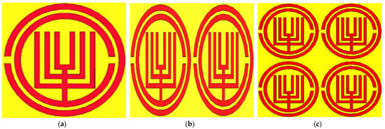
Figure 1.
Geometrical arrangement for the (a) unit cell, (b) 1 × 2 and (c) 2 × 2 array cells.

Table 1.
Dimensions of the unit cell.
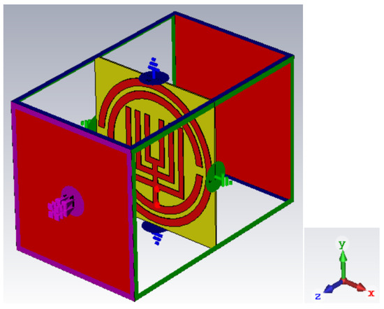
Figure 2.
Simulation set up for the proposed unit cell structure.
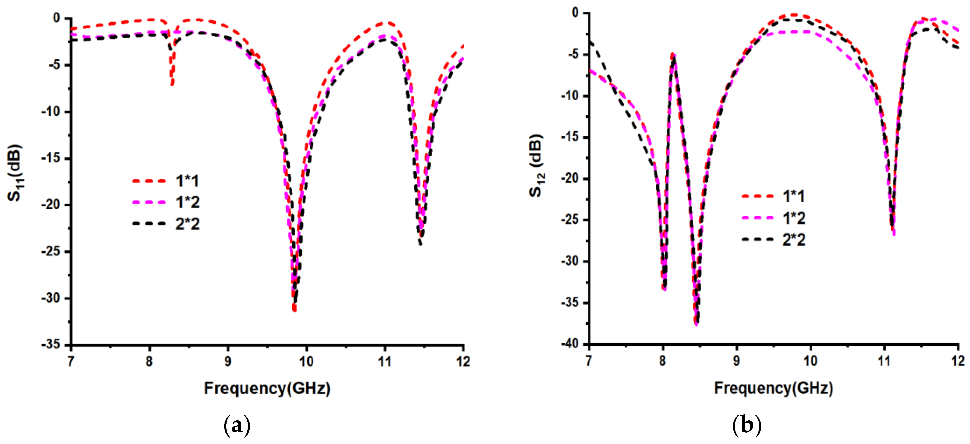
When the S11 magnitude is minimum, then the magnitude of S21 at that resonant frequency is maximum. From Figure 3a, we can conclude that for the proposed unit cell, the S11 parameter resonates at 9.84 GHz and 11.46 GHz frequencies with magnitudes −31.68 dB and −23.13 dB, respectively, and S21 for the proposed unit cell, resonated at 8 GHz, 8.435 GHz and 11.11 GHz frequencies with magnitudes of −33.20 dB, −37.13 dB and −25.89 dB, respectively. Similarly, for the 1 × 2 sized array, the S11 parameter resonates at 9.82 GHz and 11.47 GHz frequencies with magnitudes of −28.83 dB and −22.62 dB, respectively, and the S12 for the proposed unit cell was resonated at 8 GHz, 8.44 GHz and 11.10 GHz frequencies, with magnitudes of −33.20 dB, −37.59 and −26.31 dB, respectively. Finally, for the 2 × 2 sized array, the S11 parameter resonates at 9.85 GHz and 11.45 GHz frequencies with magnitudes of −30.23 dB and −24.18 dB, respectively, and the S12 for the proposed unit cell resonated at 8 GHz, 8.44 GHz and 11.09 GHz frequencies with magnitudes of −32.56 dB, −37.25 and −25.77 dB, respectively. We can thus conclude that the return loss parameter (S11) and transmission loss (S12) of various array topologies was exactly the same, with just a slight variation in the resonance frequency and its magnitude. Consequently, any size of the array structure in this suggested design yields the same response as a unit cell.
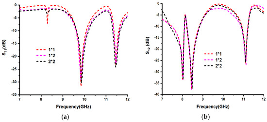
Figure 3.
(a) S11 and (b) S12 parameter results for different array sizes of the unit cell.
Validation of the Unit Cell
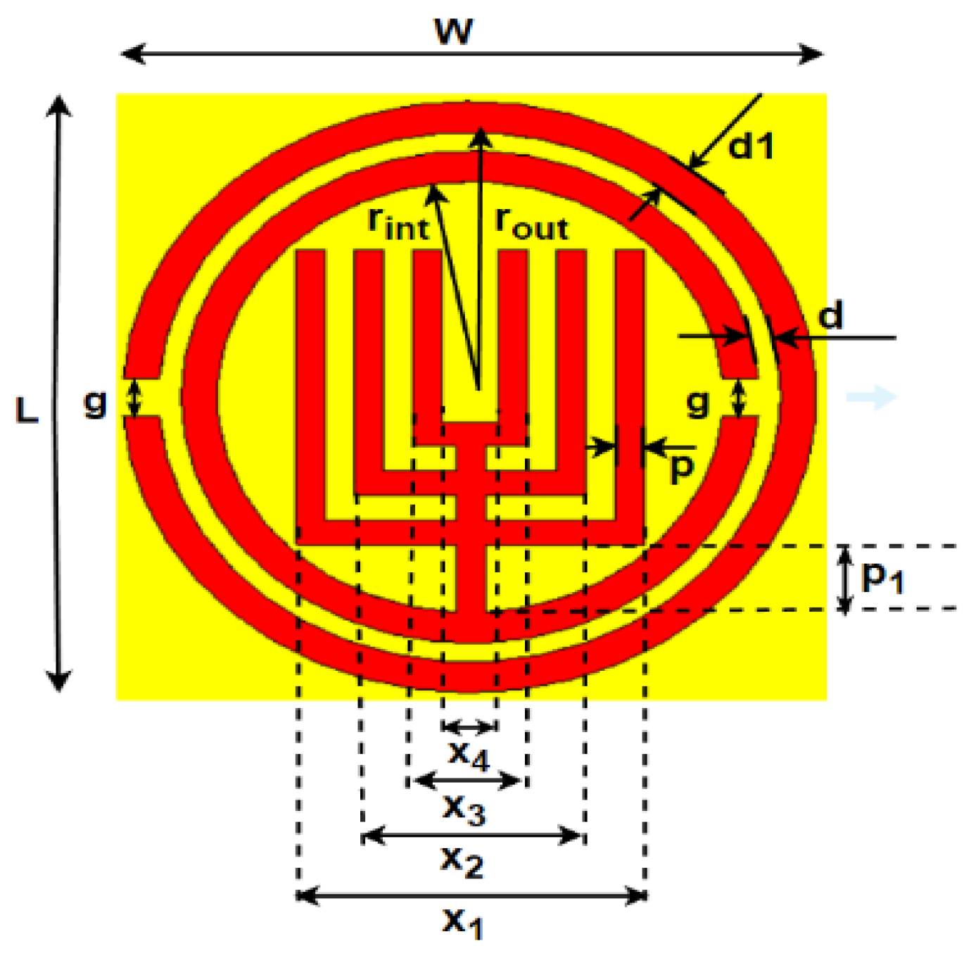
The proposed unit cell is shown in Figure 4, and its dimensions are given in Table 1. The NRW method [22,23] is chosen to verify the electromagnetic (EM) properties of the unit cell numerically. The following formulae indicate the steps to calculate and obtain the metamaterial properties by using MATLAB software.
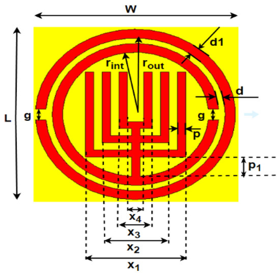
Figure 4.
Proposed structure with dimensions.
The Reflection coefficient can be written as
where Z is normalized relative impedance for S11 and S12, and can be written as the following:
The Return loss can be represented as the following equation:
The Transmission loss can be represented as the following equation:
The relative permittivity can be represented as the following equation:
The relative permeability can be represented as the following equation:
The resonant frequency of the proposed unit cell can be written as the following
where, the equivalent inductance in nH can be calculated as the following equation:
The equivalent capacitance can be calculated using the following basic capacitance equation:
Normalized relative impedance can be represented in terms of S11 and S12
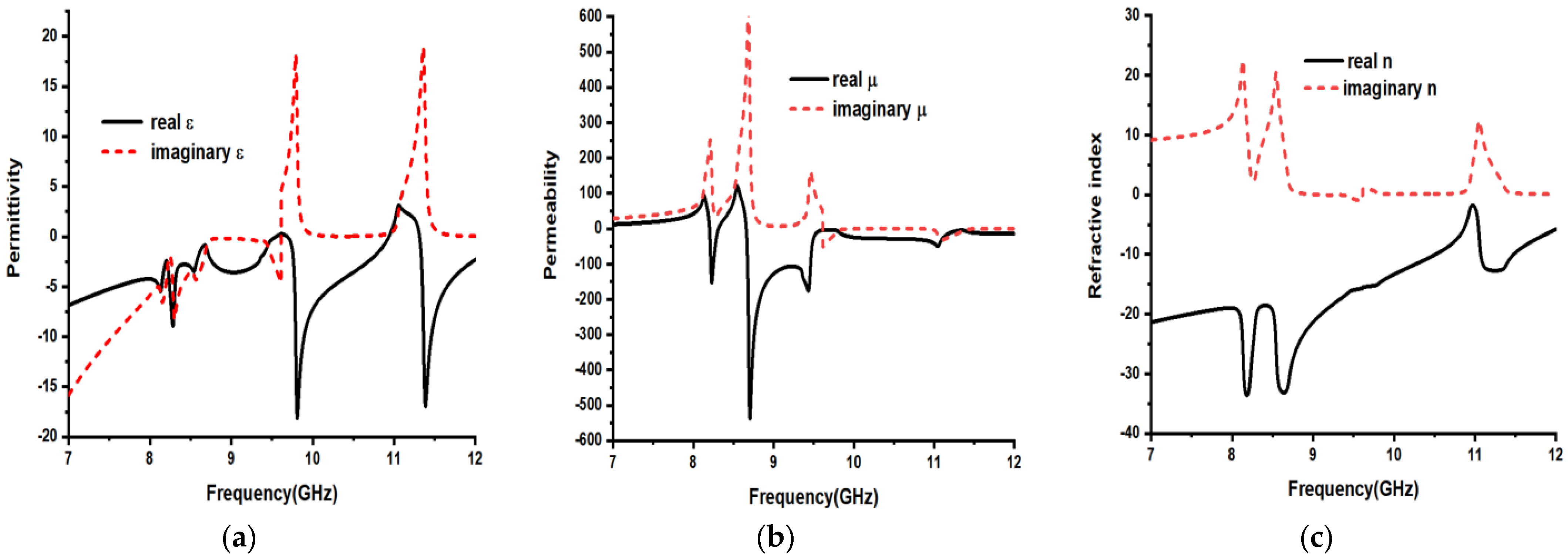
where ‘d’ is the height of the structure, ‘f’ is the resonant frequency and ‘c’ is the speed of light. The copper material strips present on the unit cell can be represented as effective inductance, and the gap present between the material strips represents capacitance. The equations from 10 to 12 can be utilized to estimate the resonant frequency, where x, y and h are the length, width and thickness of the strip, respectively. Table 2 indicates that for the unit cell’s S-parameters resonating frequency bands, the effective medium parameters like epsilon, mu and n have negative amplitudes. Finally, from Figure 5 and Table 2, we can conclude that the unit cell exhibits metamaterial properties for the corresponding frequencies.
Table 2.
Effective medium parameters frequency band operation.
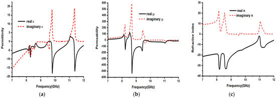
Figure 5.
The unit cell’s effective medium parameters (a) epsilon, (b) mu and (c) refractive index.
3. Measurement and Result Analysis
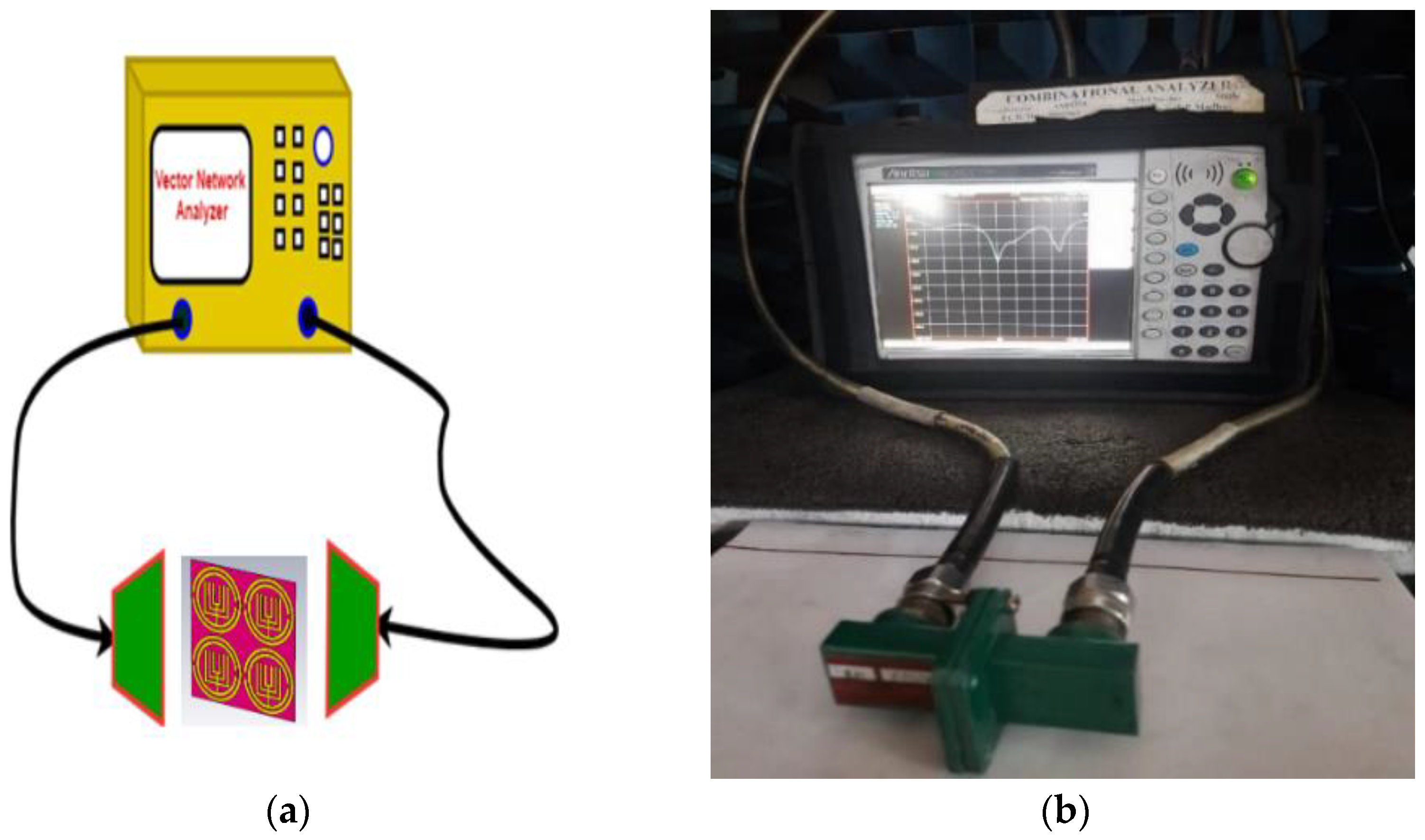
Once the S-parameters of the proposed unit cell and array were simulated using a simulation tool, such as CSTMW studio, the measurement setup for the prototype is done by placing the unit cell or meta surface array between the waveguide ports of a VNA, which is as shown in Figure 6. From the numeric simulation results, finally a 2 × 2 sized array is chosen and fabricated by using a polymide substrate, as shown in Figure 6. The polymide material has 0.1-mm thickness and a dielectric constant (εr) of 3.5. As shown in Figure 7, the measuring setup contains VNA and waveguide ports. The FSS is placed between the waveguide ports of VNA to measure scattering parameters like S11 and S12 experimentally.
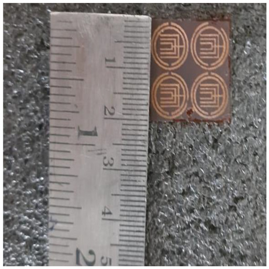
Figure 6.
Fabricated model for 2 2 array-sized FSS.
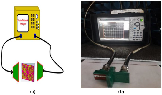
Figure 7.
Measurement setup for experimentation of FSS. (a) Measurement process. (b) Experimental setup of FSS.
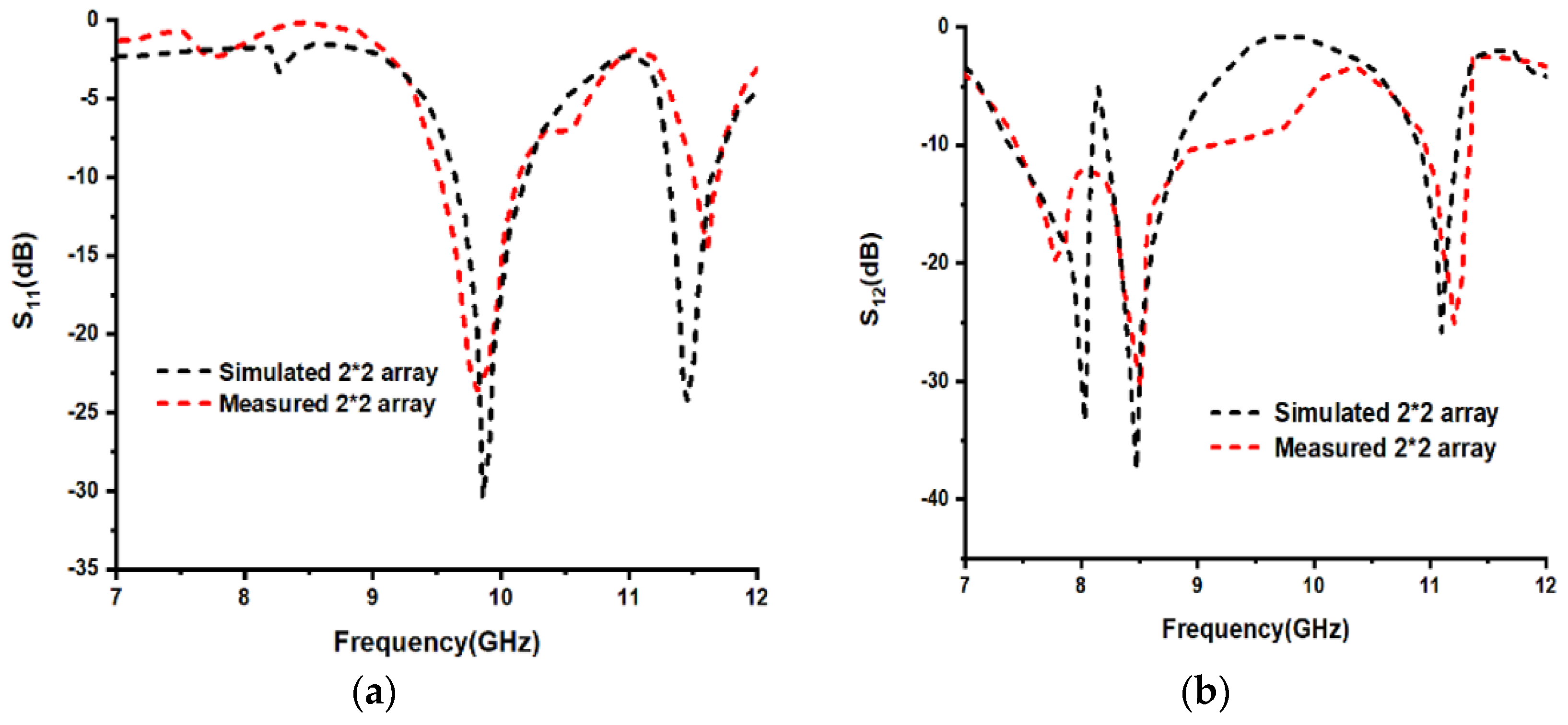
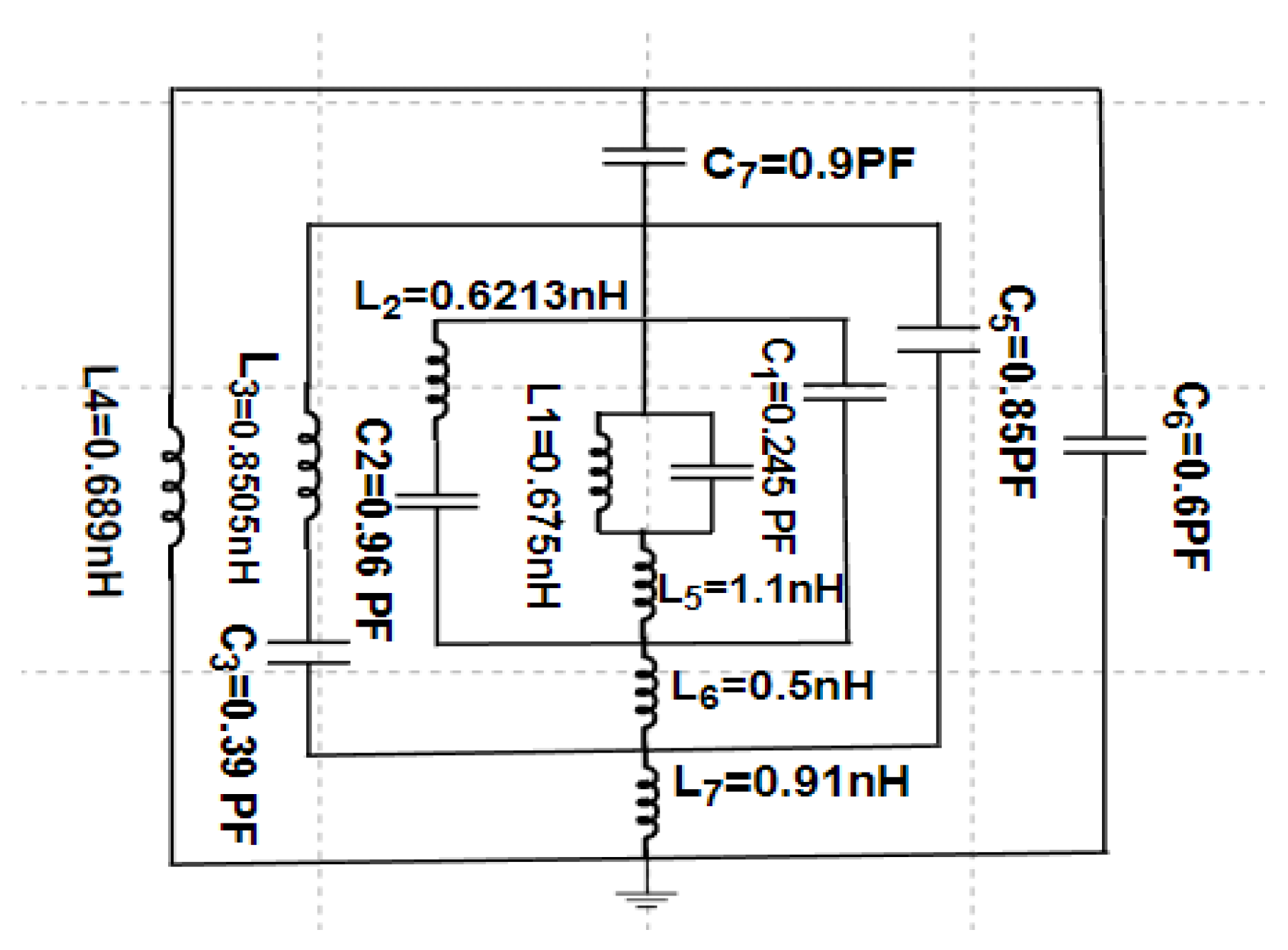
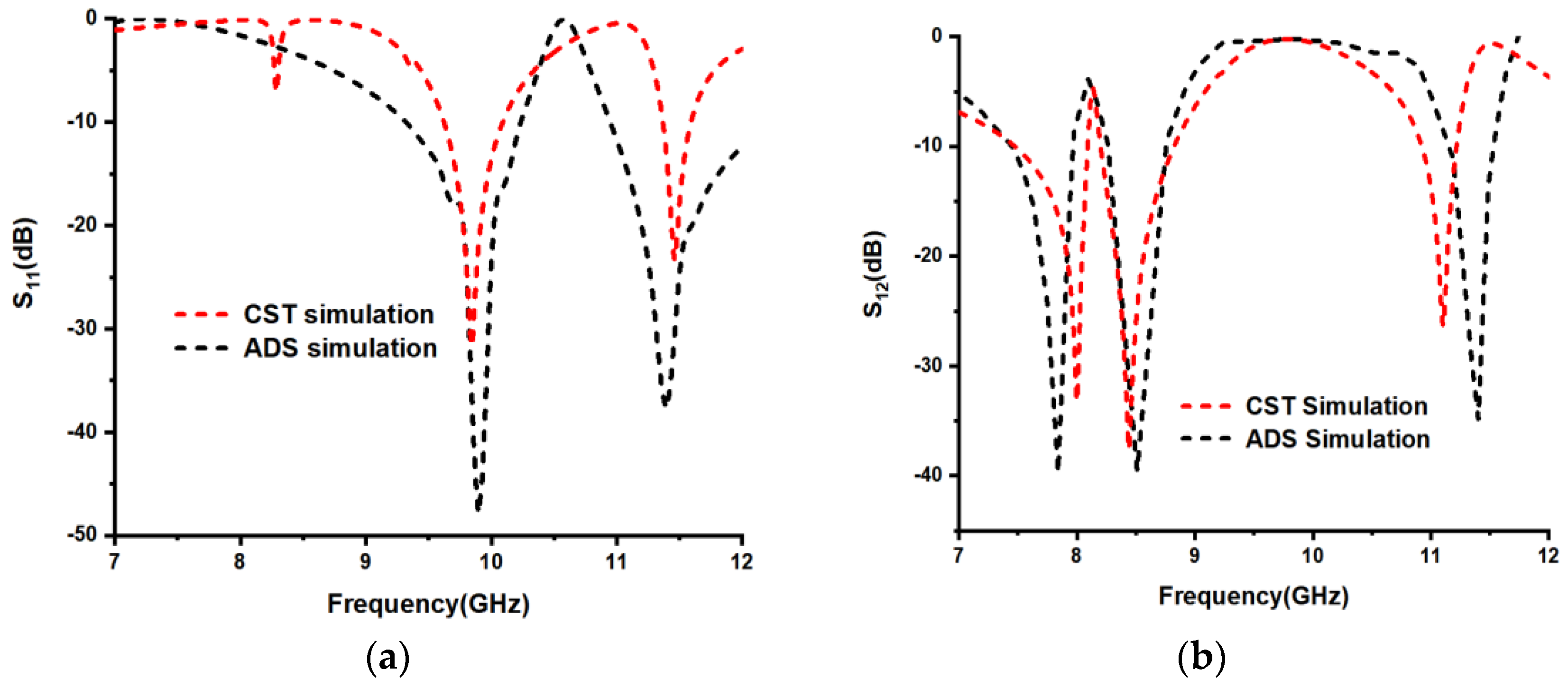
To validate the proposed unit cell, ADS software is used in this article. Figure 8 depicts the s-parameters comparison among simulated and measured results. The equivalent circuit diagram for the proposed unit cell radiating patch was drawn in the ADS tool, which is shown clearly in Figure 9. For the circuit diagram, both the input side and output sides 50 ohms are connected to provide impedance matching and to obtain the desired output. Each SRR is represented by the combination of inductance and capacitance. The proposed unit cell contains two SRRs, namely square-type SRR and circular-type SRR. In the square-type split ring resonator, the inner SRR is represented by the L1 and C1 combination, as shown in Figure 9. The middle square-type SRR, which is between inner and outer square SRRs, is represented by L2 and C2, and the outer square-type SRR is represented by L3 and C3. The strips which are present between the square-type SRRs are represented by equivalent inductances like L6 and L7, the strip present between square-type SRR and circular SRR is represented by L8 and the gaps between lower to middle square-type SRR and middle to higher square-type SRR are represented by C4 and C5, correspondingly. Finally, the gap between square-type SRR and circular SRR is represented by C7. Once the circuit is designed in ADS software, the start and stop frequencies are selected as 7 GHz and 12 GHz, correspondingly, in the S-parameters section of the ADS tool with a step size of 100 MHz. By using the tuning option, in the ADS tool, the lumped parameters were tuned and obtained the return loss plot, as shown in Figure 10. For the CST-based unit cell simulation, the reflection coefficient resonates at 9.84 GHz and 11.46 GHz frequencies, with reflection coefficient values of −31.68 dB and −23.13 dB, correspondingly, and the transmission coefficient resonates at 8 GHz, 8.435 GHz and 11.11 GHz frequencies, with transmission coefficient values of −33.20 dB, −37.13 and −25.89 dB, correspondingly. By using ADS simulation, the reflection coefficient resonates at 9.9 GHz and 11.4 GHz, with reflection coefficient amplitudes of −47.82 dB −37.57 dB, correspondingly, and the transmission coefficient resonates at 7.83 GHz, 8.51 GHz and 11.40 GHz frequencies, with transmission coefficient amplitudes of −39.72 dB, −39.56 dB and −34.81 dB, correspondingly. The proposed FSS-fabricated model is shown in Figure 6, and the measuring process for measuring S-parameters for fabricated FSS is shown clearly in Figure 7. From Figure 8, it is seen that in the CST-simulated results for a 2 × 2 array-sized unit cell, the return loss plot resonates at 9.85 GHz and 11.45 GHz frequencies, with reflection coefficients of −30.23 dB and −24.18 dB, correspondingly, and the transmission coefficient resonates at 8 GHz, 8.44 GHz and 11.09 GHz frequencies, with transmission coefficient values of −32.56 dB, −37.25 and −25.77 dB, correspondingly, and after measuring the proposed FSS, it resonates at 9.81 GHz and 11.61 GHz frequencies, with reflection coefficients of −23.55 dB and −14.36 dB, correspondingly, and the transmission coefficient resonates at 7.77 GHz, 8.51 GHz and 11.20 GHz frequencies, with transmission coefficients of −19.72 dB, −30.54 and −25.02 dB, correspondingly.
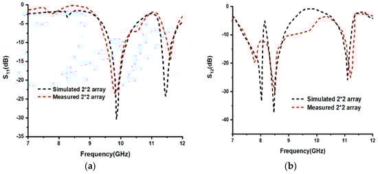
Figure 8.
Simulated and measured plots for (a) S11 (b) S12 parameters.
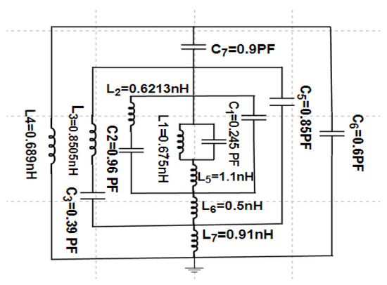
Figure 9.
The equivalent circuit diagram for the unit cell designed in the ADS tool.

Figure 10.
Unit cell’s (a) S11 and (b) S12 simulated plots for both CST and ADS tools.
3.1. Parametric Analysis for the Radiating Patch
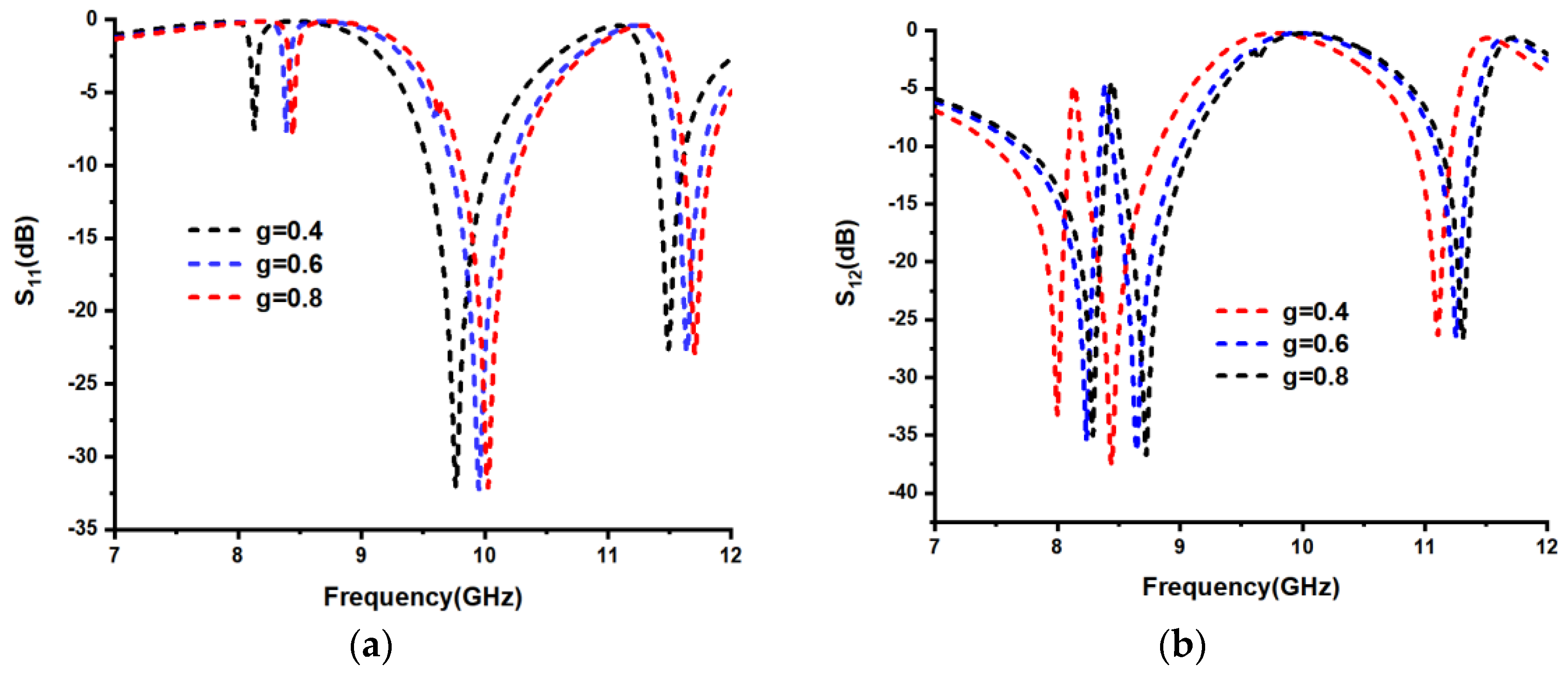
The split gap is one of the essential criteria to evaluate the effectiveness of any metamaterial-based structure. The frequency of any structure depends on inductance and capacitance values. The inductance value depends on the length, width and thickness of the metal, and the capacitance value depends on a split gap (g) in the design. Depending on the split gap, the capacitance values are changed. It should be noted that the split can be represented as a capacitance. As the split gap of any SRR grows, the frequency also increases due to a decrease in capacitance value. Parametric analysis for the split gap of the proposed circular type SRR with a lower limit of 0.4 mm and an upper limit of 0.8 mm with 0.2 mm step width is shown in Figure 11 and Figure 12.
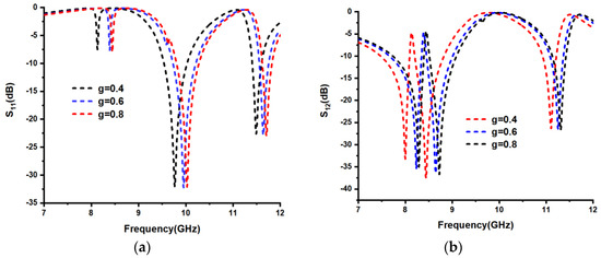
Figure 11.
(a) S11 and (b) S12 parameters plots for the variation of split gap (g) of the proposed unit cell.
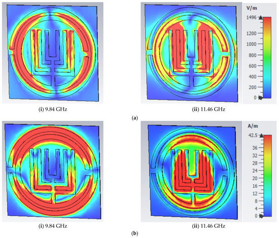

Figure 12.
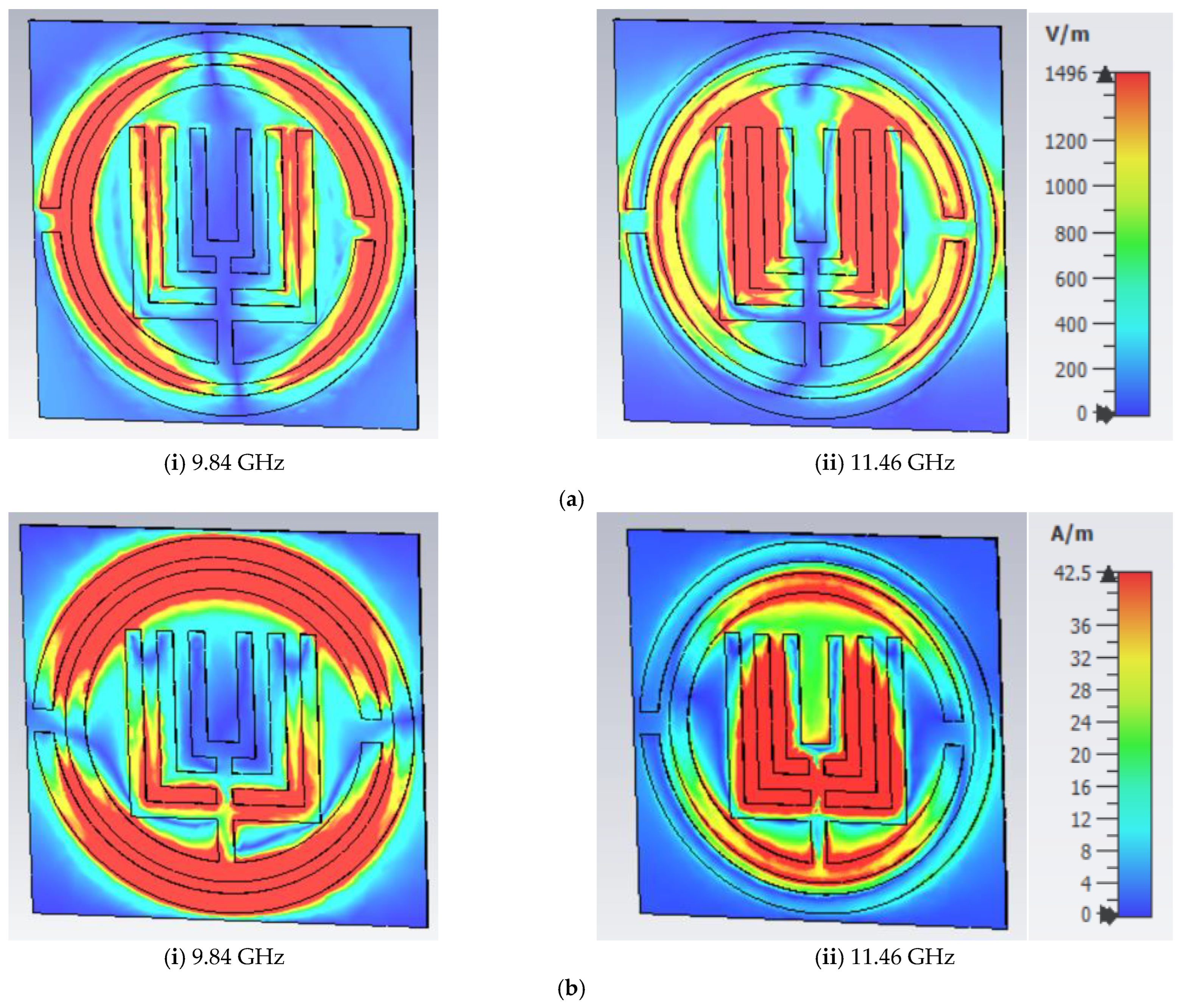
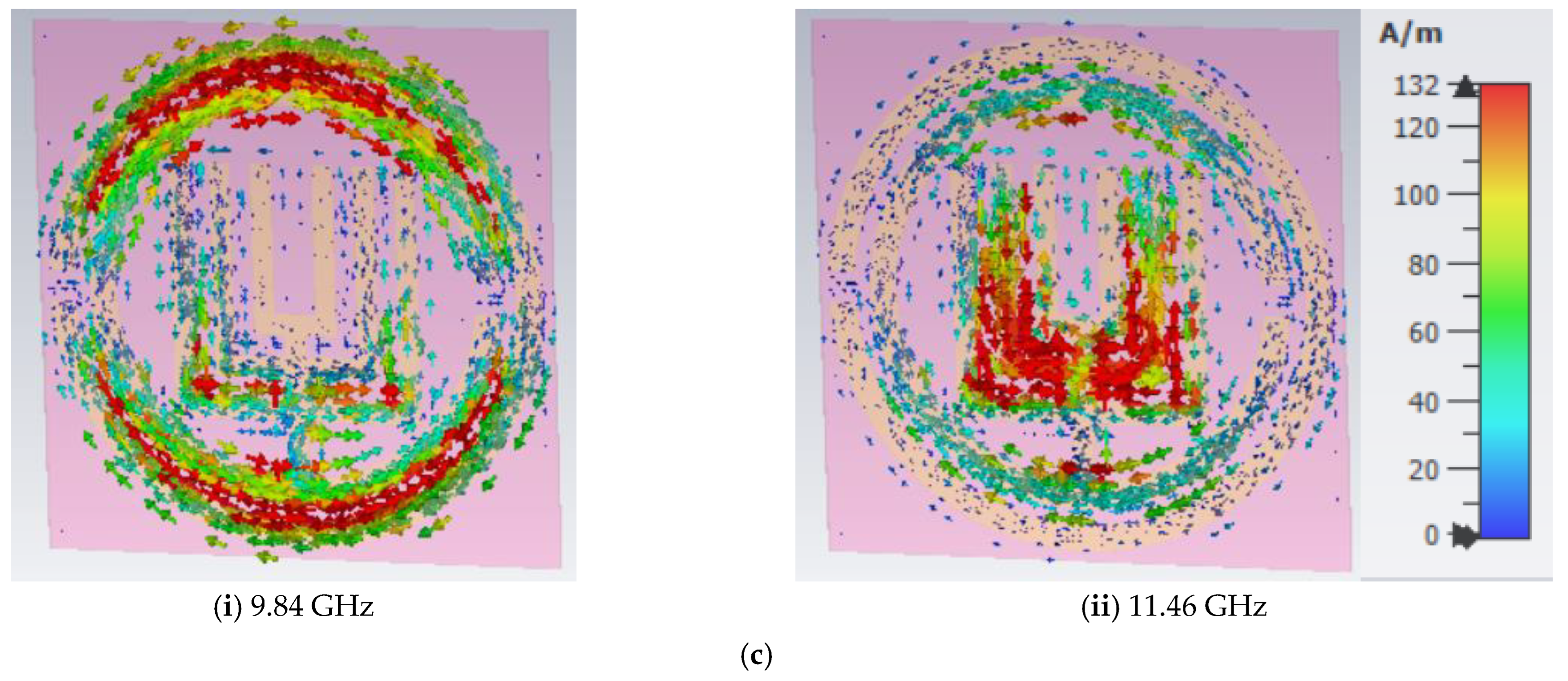
(a) E-field distribution, (b) H-field distribution and (c) surface current distributions of proposed structure at 9.84 GHz and 11.46 GHz frequencies.
When the split gap of the proposed unit cell is varied for the split gaps 0.4, 0.6 and 0.8 mm, the corresponding return loss plot resonates at two different frequencies. For a 0.4 mm gap, the S11 resonates at 9.77 GHz with a magnitude of −31.97 dB. For 0.6 mm, the S11 resonates at 9.95 GHz with a magnitude of −32.12 dB, and for the 0.8 mm gap, the S11 resonates at 10.02 GHz with a magnitude of −32.11 dB. Similarly, the second S11 frequency for 0.4, 0.6 and 0.8 mm split gaps resonates at 11.48 GHz, 11.63 GHz and 11.71 GHz with −22.42 dB, −22.74 dB and −22.81 dB, correspondingly. The unit cell transmission coefficient (S12) possesses three different frequencies. For a 0.4 mm split gap, the S12 resonates at 8 GHz, 8.44 GHz and 11.10 GHz frequencies with amplitudes of −33.20 dB,−37.25 dB and −26.31 dB, correspondingly. For a 0.6 mm gap, the S12 resonates at 8.23 GHz, 8.64 GHz and 11.25 GHz frequencies with S12 amplitudes of −35.44 dB,−35.86 dB and −26.25 dB, correspondingly. For a 0.8 mm gap, S12 resonates at 8.29 GHz, 8.72 GHz and 11.31 GHz frequencies with S12 amplitudes of −34.99 dB, −36.50 dB and −26.64 dB, correspondingly. According to X-band frequency applications, a final split gap of 0.2 mm was selected for the proposed unit cell.
3.2. E, H and Zurface Current Analysis of the Proposed Structure
Fundamentally, the unit cell’s radiating patch includes two SRRs, and each of them corresponds to a frequency. From Figure 12, we can say that the radiating patch of the proposed unit cell resonates at two different frequencies: 9.84 GHz and 11.46 GHz, correspondingly. The E-field is stronger on the circular-typed SRR, which corresponds to the 9.84 GHz frequency, and similarly, a strong E-field is formed on the square-typed SRR, which corresponds to the 11.46 GHz frequency. Finally, we can conclude that both E and H-fields for two frequencies are excited in the opposite direction, which is the principle satisfying the Maxwell equations.
3.3. Bending Analysis for the Proposed Design
Bending analysis is required to justify the structure performance with bending angles [24,25] and to talk about the flexibility of the dielectric material. Due to the small unit cell size and similar responses between the unit cell and 2 × 2 array-sized FSS, we have considered a 2 × 2 fabricated model for the bending analysis of the structure.
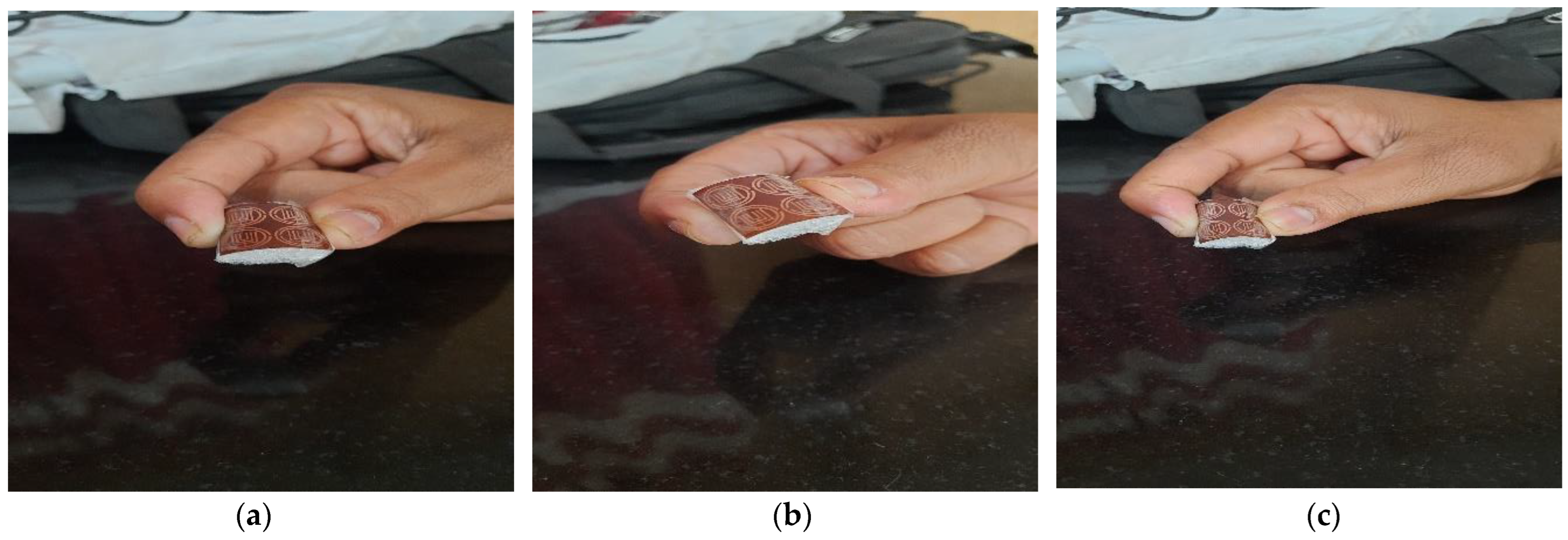
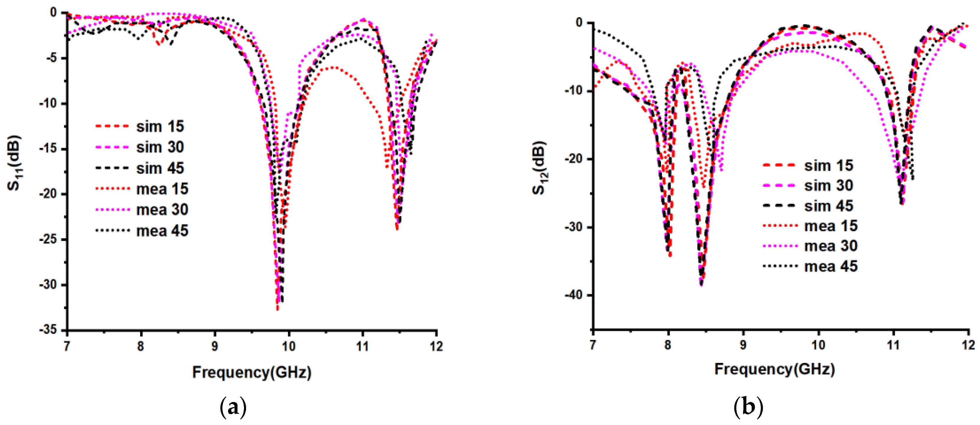
As shown in Figure 13, the proposed unit cell is bent with three different bending angles 15, 30 and 45 degrees, using the simulation tool, and Figure 14 explains the fabricated 2 × 2 array-sized model with three different bending angles like 15, 30 and 45 degrees. The corresponding S-parameters were calculated for both simulation and measurement, and are clearly shown in Figure 15. From Figure 15, we can observe that with the simulation of a 15-degree bent unit cell, the frequencies obtained for S11 are 9.84 GHz and 11.50 GHz, with S11 amplitudes of −32.69 dB and −23.30 dB, correspondingly, while the obtained frequencies for the S12 are 8.02 GHz, 8.46 GHz and 11.09 GHz, with S12 amplitudes of −34.17 dB, −37.46 dB and −26.55 dB, correspondingly. For a 30-degree bent unit cell, the frequencies for S11 are 9.86 GHz and 11.50 GHz with S11 amplitudes of −31.81 dB and −23.30 dB, correspondingly, while the obtained frequencies for the S12 are 7.99 GHz, 8.43 GHz and 11.09 GHz, with S12 amplitudes of −33.37 dB, −38.30 dB and −26.53 dB, correspondingly. For a 45-degree bent unit cell, the obtained frequencies for S11 are 9.91 GHz and 11.50 GHz with S11 amplitudes of −32.05 dB and −23.30 dB, correspondingly, and the obtained frequencies for the S12 are 7.99 GHz, 8.43 GHz and 11.09 GHz, with S12 amplitudes of −33.37 dB, −38.30 dB and −26.55 dB, correspondingly. Whereas for the measurement process for the fabricated prototype, which is shown in Figure 14, the corresponding S11 obtained frequencies for the 15-degree bent prototype are 9.94 GHz and 11.32 GHz with S11 amplitudes of −23.66 dB and −17.23 dB, correspondingly, while the frequencies obtained for the S12 are 7.88 GHz, 8.46 GHz and 11.16 GHz, with S12 amplitudes of −21.96 dB, −24.21 dB and −15.28 dB, correspondingly. For the 30-degree bent for the proposed prototype, the corresponding S11 frequencies are 9.88 GHz and 11.43 GHz with S11 amplitudes of −17.65 dB and −18.45 dB, correspondingly, and the obtained frequencies for the S12 are 7.96 GHz, 8.70 GHz and 11.08 GHz, with S12 amplitudes of −17.78 dB, −21.68 dB and −24.02 dB, correspondingly, and for the 45-degree bend for the proposed prototype, the corresponding S11 frequencies are 9.74 GHz and 11.65 GHz with S11 amplitudes of −15.81 dB and −15.53 dB, correspondingly, while the obtained frequencies for S12 are 7.96 GHz, 8.60 GHz and 11.25 GHz, with S12 amplitudes of −17.29 dB, −19.16 dB and −23.06 dB, correspondingly. From Figure 16, Figure 17 and Figure 18, we can say that the field distributions are also not much affected even with the bending of the substrate material. From Table 3, it can be noted that the present work is based on a polyimide dielectric substrate material, which is a flexible and lightweight dielectric material. This work is exactly suitable for x-band applications.
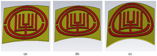
Figure 13.
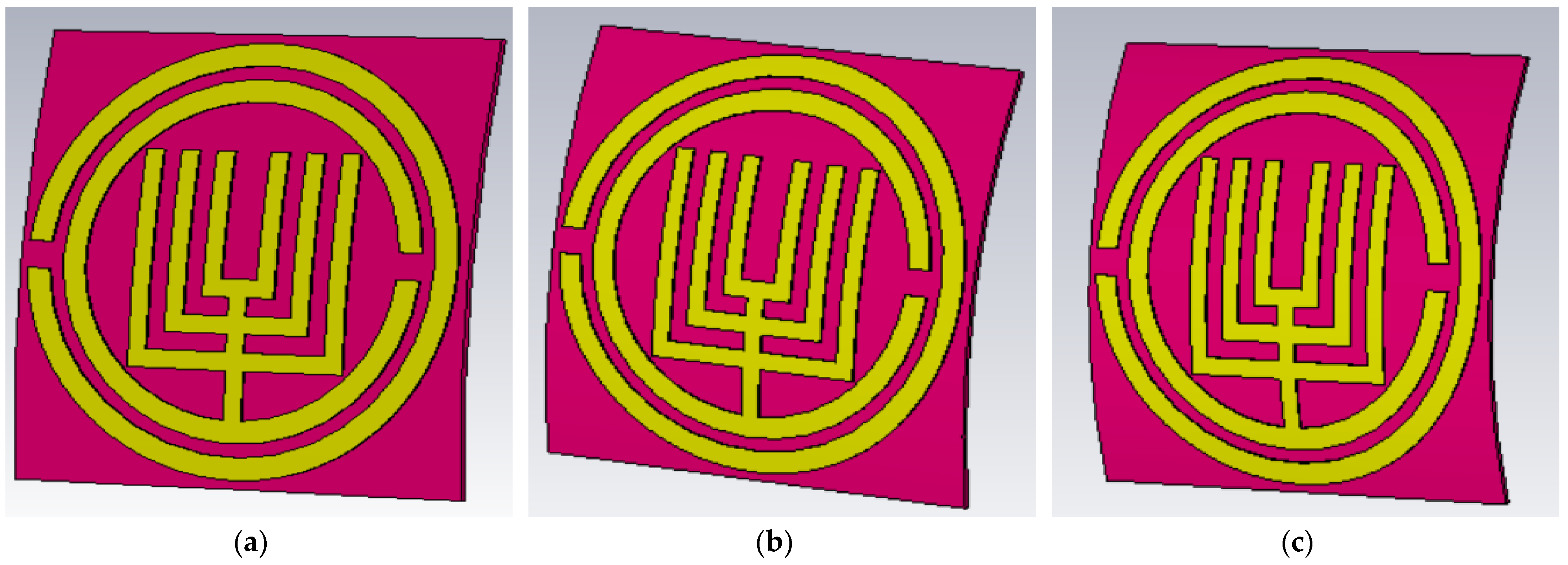
Proposed structure using simulation for (a) 15, (b) 30 and (c) 45 degrees horizontal bending case.

Figure 14.
The fabricated 2 × 2 array size for horizontal bending angles for (a) 15, (b) 30 and (c) 45 degrees.
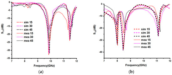
Figure 15.
The simulated and measured S-parameters (a) S11 and (b) S12 for horizontal bending angles (in degrees).
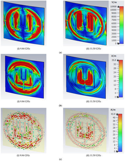
Figure 16.
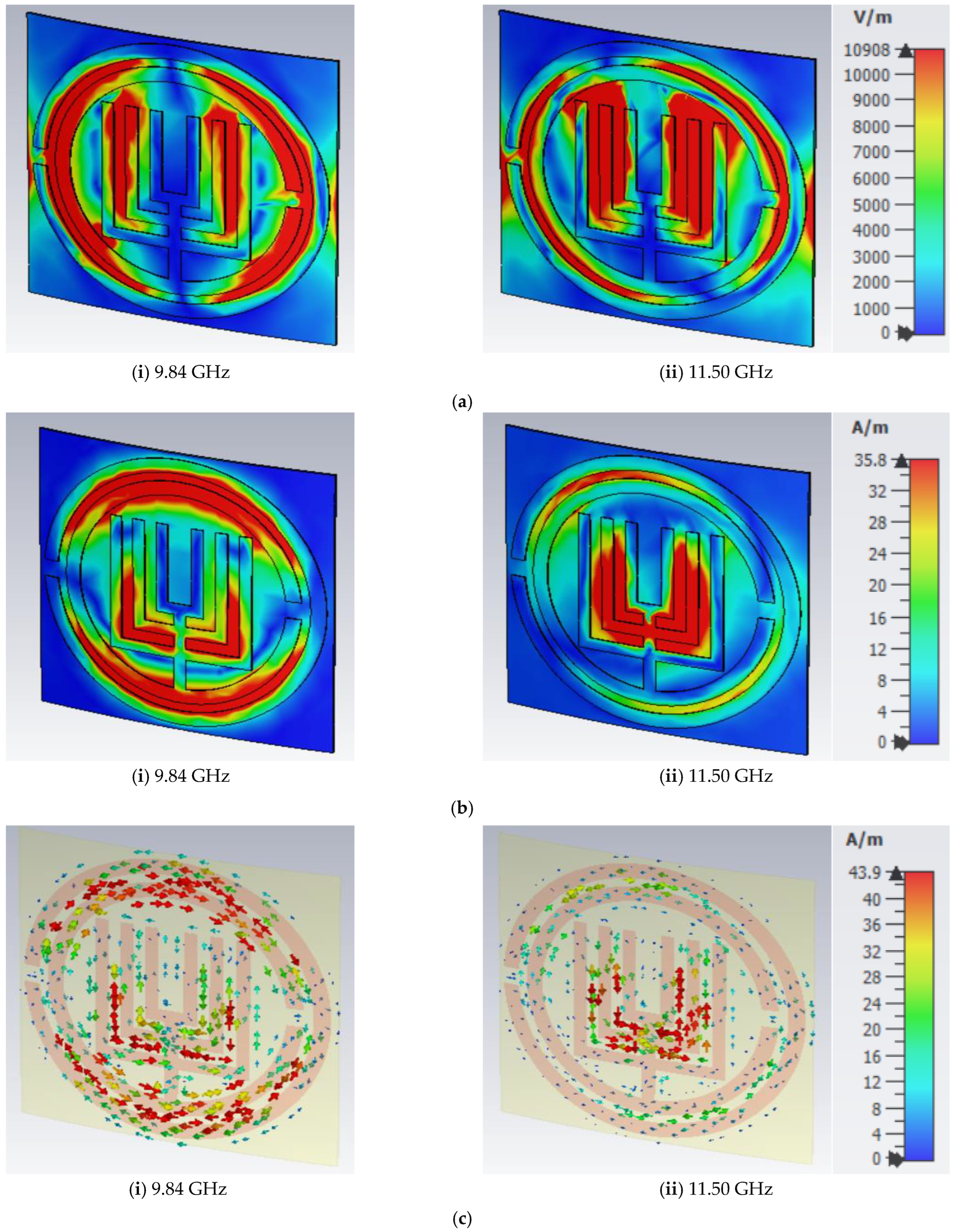
(a) E-field distribution, (b) H-field distribution and (c) surface current distributions of proposed structure at 9.84 GHz and 11.50 GHz frequencies with 15° horizontal bending.
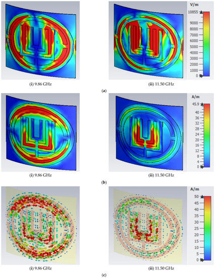
Figure 17.
(a) E-field distribution, (b) H-field distribution and (c) surface current distributions of proposed structure at 9.86 GHz and 11.50 GHz frequencies with 30° horizontal bending.

Figure 18.
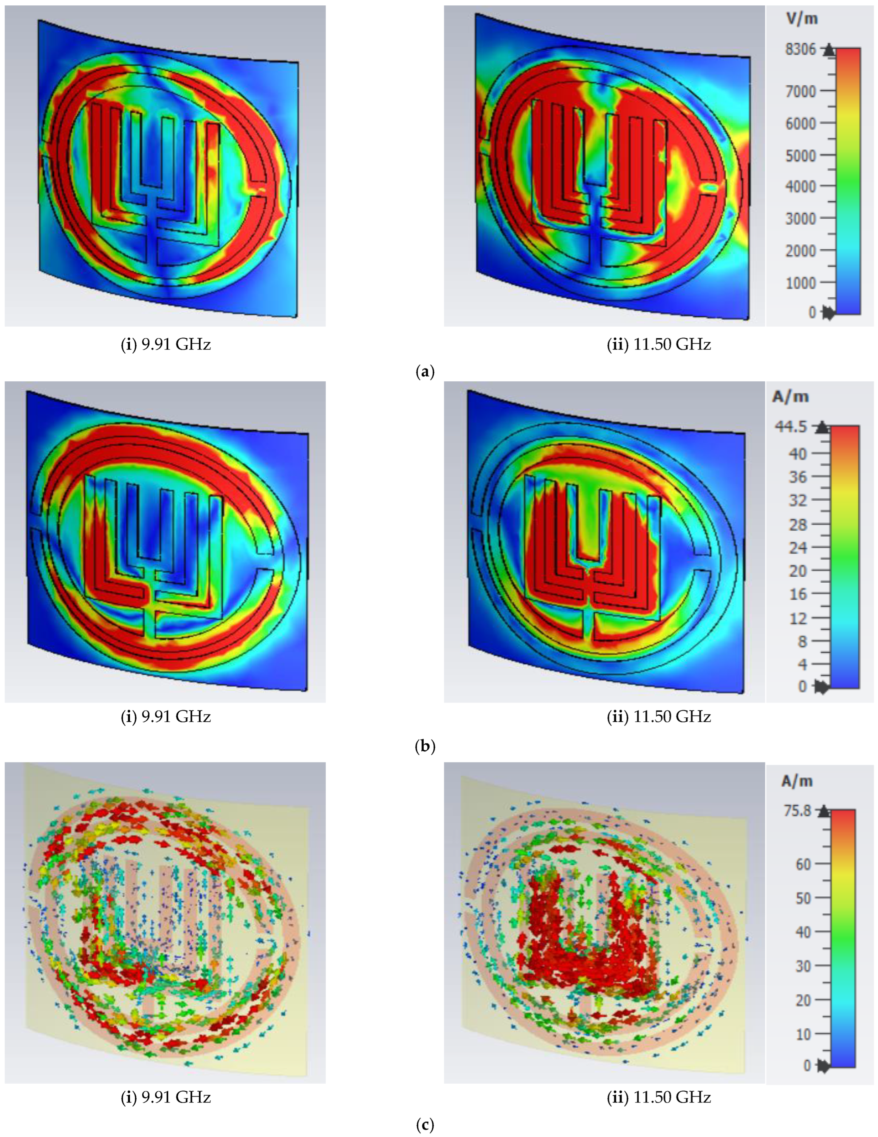
(a) E-field distribution, (b) H-field distribution and (c) surface current distributions of proposed structure at 9.91 GHz and 11.50 GHz frequencies, respectively, with 45° horizontal bending.
Table 3.
Comparison table with existing work.
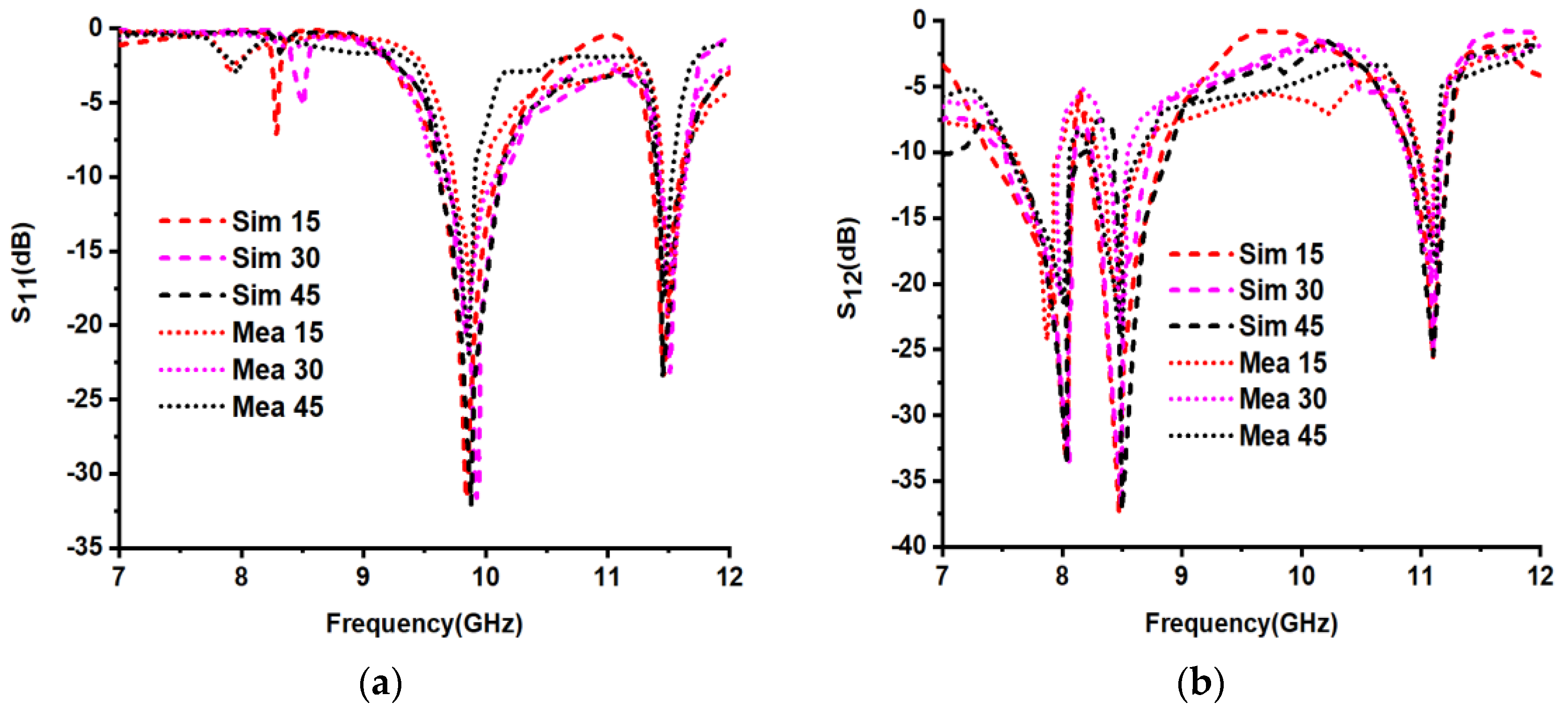
As shown in Figure 19 explains about the fabricated 2 × 2 array-sized model with three different bending angles, 15, 30 and 45 degrees. While Figure 20 shows the proposed unit cell is bent vertically with three different bending angles 15, 30 and 45 degrees using the simulation tool. The corresponding current distribution and S-parameters were calculated for both simulation and measurement, and are clearly shown in Figure 21, Figure 22, Figure 23 and Figure 24. From Figure 24, we can observe that with the simulation of a 15-degree bent unit cell, the obtained frequencies for S11 are 9.83 GHz and 11.47 GHz, with S11 amplitudes of −30.98 dB and −21.90 dB, correspondingly, while the obtained frequencies for the S12 are 8.01 GHz, 8.47 GHz and 11.09 GHz, with S12 amplitudes of −33.41 dB, −37.51 dB and −26.79 dB, correspondingly. For a 30-degree bent unit cell, the frequencies for S11 are 9.92 GHz and 11.46 GHz with S11 amplitudes of −31.60 dB and −23.13 dB, correspondingly, while the obtained frequencies for the S12 are 8.02 GHz, 8.46 GHz and 11.10 GHz, with S12 amplitudes of −33.41 dB, −37.13 s dB and −25.42 dB, correspondingly. For a 45-degree bent unit cell, the obtained frequencies for S11 are 9.87 GHz and 11.46 GHz with S11 amplitudes of −31.68 dB and −23.29 dB, correspondingly, and the obtained frequencies for the S12 are 8.02 GHz, 8.5 GHz and 11.09 GHz, with S12 amplitudes of −33.40 dB, −37.23 dB and −25.79 dB, correspondingly. In the measurement process for the fabricated prototype, which is shown in Figure 19, the corresponding S11 obtained frequencies for the 15-degree vertically bent prototype are 9.88 GHz and 11.31 GHz with S11 amplitudes of −17.25 dB and −16.78 dB, correspondingly, while the obtained frequencies for the S12 are 7.87 GHz, 8.51 GHz and 11.16 GHz, with S12 amplitudes of −24.31 dB, −20.78 dB and −15.28 dB, correspondingly. A 30-degree bent for the proposed prototype, the corresponding S11 frequencies are 9.88 GHz and 11.43 GHz with S11 amplitudes of −17.25 dB and −17.32 dB, correspondingly, and the obtained frequencies for the S12 are 7.99 GHz, 8.68 GHz and 11.09 GHz, with S12 amplitudes of −16.90 dB, −20.57 dB and −24.02 dB, correspondingly, and for a 45-degree bend for the proposed prototype, the corresponding S11 frequencies are 9.72 GHz and 11.41 GHz with S11 amplitudes of −16.02 dB and −15.78 dB, correspondingly, while the obtained frequencies for S12 are 7.99 GHz, 8.50 GHz and 11.33 GHz, with S12 amplitudes of −16.93 dB, −20.05 dB and −20.06 dB, correspondingly. From Figure 21, Figure 22 and Figure 23, we can say that the field distributions are also not much affected even with the vertical bending of the structure. From Table 3, it can be noted that the present work is based on a polyimide dielectric substrate material, which is a flexible and lightweight dielectric material. This work is exactly suitable for X-band applications.
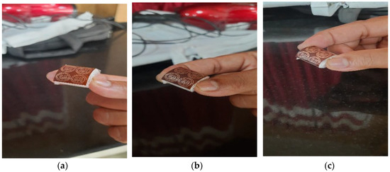
Figure 19.
Proposed 2 × 2 array sized fabricated structure for (a) 15, (b) 30 and (c) 45 degrees vertical bending case.
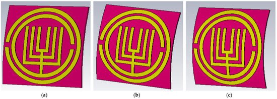
Figure 20.
The simulated unit cell for vertical bending angles (a) 15, (b) 30 and (c) 45 degrees.
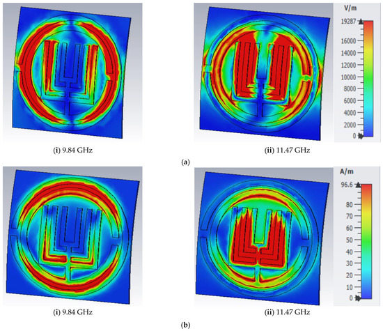
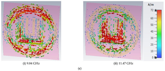
Figure 21.
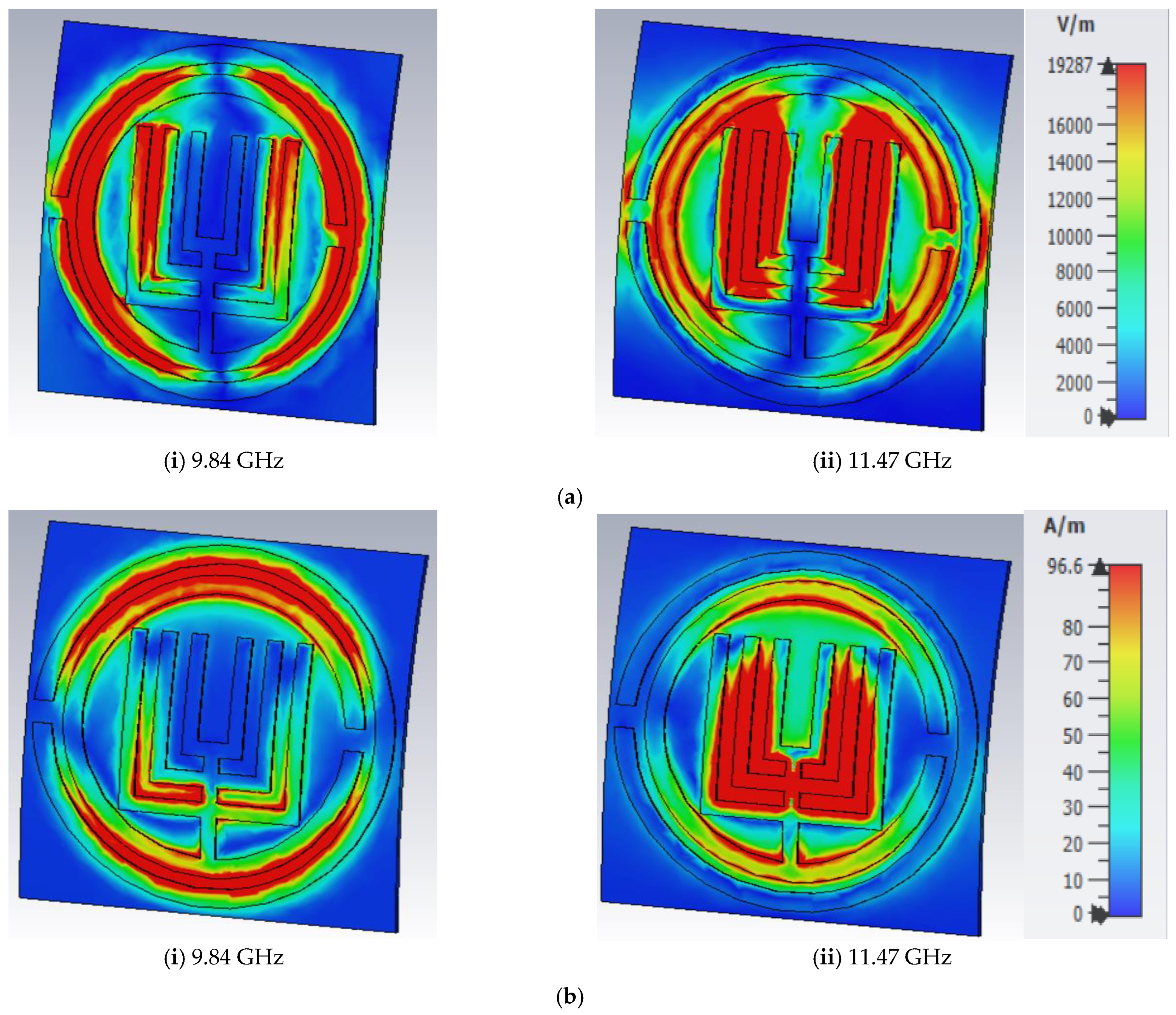
(a) E-field distribution, (b) H-field distribution and (c) surface current distributions of the proposed structure at 9.84 GHz and 11.47 GHz with 15° vertical bending.

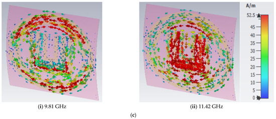
Figure 22.
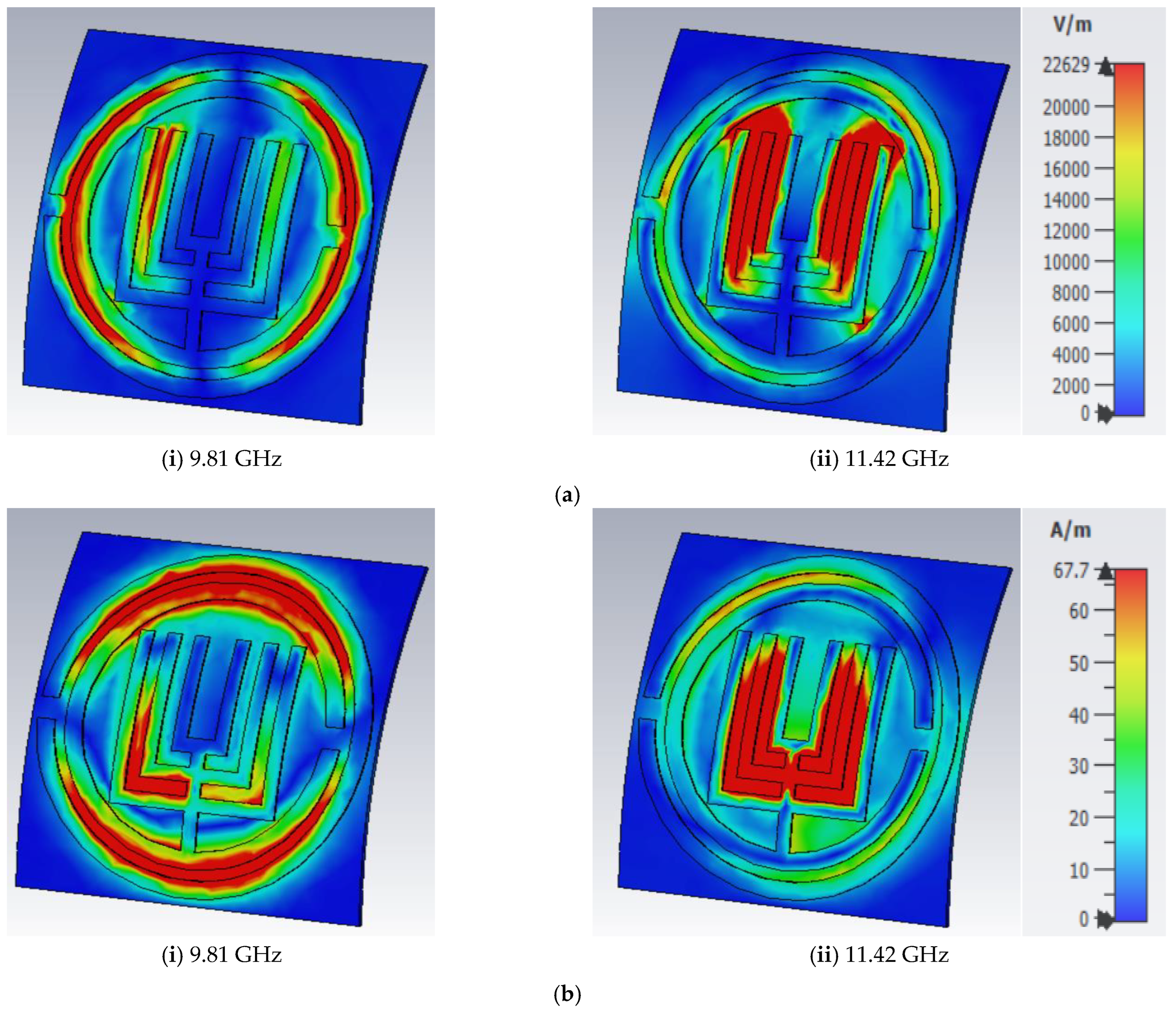
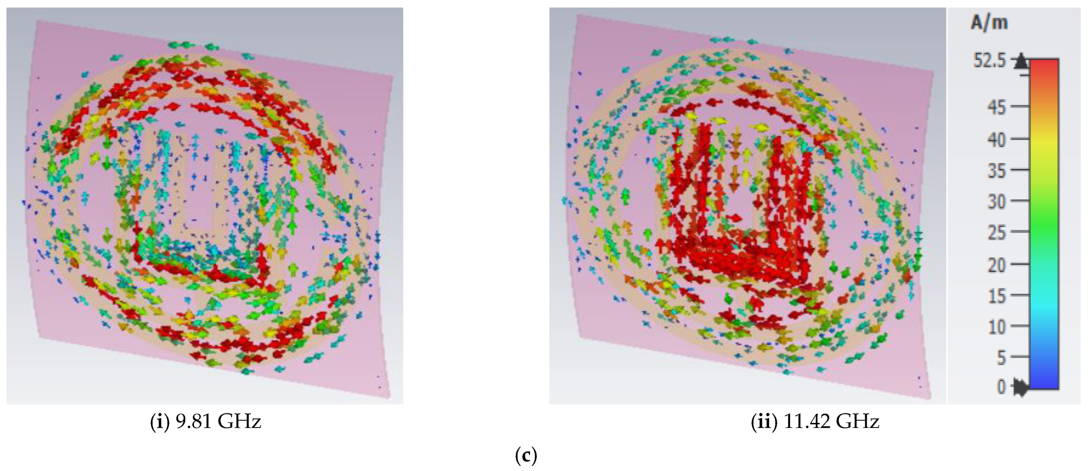
(a) E-field distribution, (b) H-field distribution and (c) surface current distributions of the proposed structure at 9.81 GHz and 11.42 GHz with 30° vertical bending.
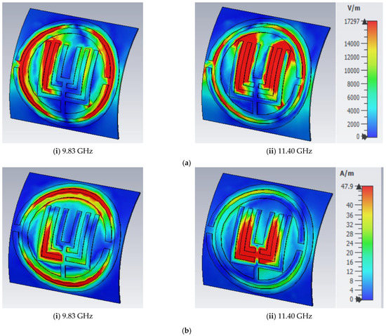
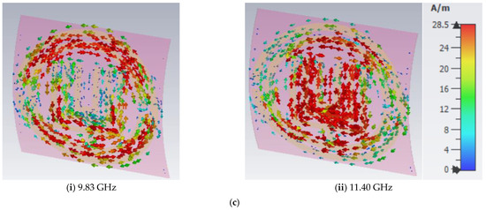
Figure 23.
(a) E-field distribution, (b) H-field distribution and (c) surface current distributions of the proposed structure at 9.83 GHz and 11.40 GHz with 45° vertical bending.
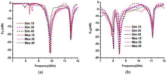
Figure 24.
The simulated and measured S-parameters (a) S11 and (b) S12 for vertical bending angles (in degrees).
4. Discussion
Mostly all the radar applications, like weather forecasting, military, navigation, remote sensing and so on, operate within the X-band frequency range. Metamaterials allow for the extreme downsizing of existing devices. From the given comparison table, we can deduce that the proposed structure is well suited for X-band applications with flexible and light-thickness polymide dielectric substrate material, rather than that of FR4, Rogers and etc. From [6], we can observe that the unit cell size is taken as 12 × 12 mm2, and produces only a single resonant frequency within the X-frequency band. Similarly, from [18], we can observe that the absorber is working at a single frequency within the X-band frequency. We may also deduce from the entire comparison table that no dual frequencies were present in the X-band, which is a significant benefit over all other methods of producing dual bands. In addition, in contrast to previous studies, the proposed design demonstrated left-handed metamaterial characteristics at two resonant frequencies within the X-band. Nowadays, other flexible materials are also available, such as paper, jeans and so on, with less thickness and less dielectric constant values, rather than this polymide substrate material to design the FSS. Furthermore, we are interested in designing metamaterial structures with less thickness.
5. Conclusions
The circular and square-shaped SRRs with left-handed metamaterial properties were demonstrated in this work. For the CST-based unit cell simulation, the reflection coefficient resonates at 9.84 GHz and 11.46 GHz frequencies, and the transmission coefficient resonates at 8 GHz, 8.43 GHz and 11.11 GHz frequencies, correspondingly, and using ADS simulation, the reflection coefficient resonates at 9.9 GHz and 11.40 GHz and the transmission coefficient resonates at 7.83 GHz, 8.51 GHz and 11.40 GHz frequencies, correspondingly. From both simulations (ADS and CST), the S-parameters frequency values are almost similar, with a small variation in frequencies. The simulated return loss frequencies for a 2 × 2 array-sized unit cell are 9.85 GHz and 11. 45 GHz, and the transmission coefficient resonates at 8 GHz, 8.44 GHz and 11.09 GHz, correspondingly. Similarly, for the 2 × 2 array-sized fabricated model, the return losses are at 9.81 GHz and 11.61 GHz and the transmission coefficient resonates at 7.77 GHz, 8.51 GHz and 11.20 GHz, correspondingly. According to the results and discussion, the S-parameters (S11 and S12) of the proposed design experimental results were matched to the simulated data with a slight change. Hence, the proposed FSS is exactly suitable for X-band applications with flexible and compact-sized polymide substrate.
Author Contributions
Conceptualization, N.P., P.P. and B.T.P.M.; methodology, N.P., P.P. and S.D.; software, N.P., P.P. and N.H.; validation, B.T.P.M. and S.D.; writing—original draft preparation, N.P., P.P. and B.T.P.M.; writing—review and editing, S.D., W.A.A. and N.H.; supervision, B.T.P.M. and S.D.; project administration, N.H. and funding acquisition, W.A.A. and N.H. All authors have read and agreed to the published version of the manuscript.
Funding
This research received no external funding.
Institutional Review Board Statement
Not applicable.
Informed Consent Statement
Not applicable.
Data Availability Statement
The data presented in this research are available on request from the corresponding author.
Conflicts of Interest
The authors declare no conflict of interest.
References
- Islam, M.T.; Islam, M.R.; Islam, M.T.; Hoque, A.; Samsuzzaman, M. Linear regression of sensitivity for meander line parasitic resonator based on ENG metamaterial in the application of sensing. J. Mater. Res. Technol. 2021, 10, 1103–1121. [Google Scholar] [CrossRef]
- Galaydych, V.; Azarenkov, M. Slow surface electromagnetic waves on a mu-negative medium. Appl. Phys. B 2022, 128, 132. [Google Scholar] [CrossRef]
- Hakim, M.L.; Alam, T.; Soliman, M.S.; Sahar, N.M.; Baharuddin, M.H.; Almalki, S.H.; Islam, M.T. Polarization insensitive symmetrical structured double negative (DNG) metamaterial absorber for Ku-band sensing applications. Sci. Rep. 2022, 12, 1–8. [Google Scholar]
- Zhou, Q.; Xue, B.; Gu, S.; Ye, F.; Fan, X.; Duan, W. Ultra broadband electromagnetic wave absorbing and scattering properties of flexible sandwich cylindrical water-based metamaterials. Results Phys. 2022, 38, 105587. [Google Scholar] [CrossRef]
- Esmail, B.A.; Koziel, S.; Szczepanski, S. Overview of planar antenna loading metamaterials for gain performance enhancement: The two decades of progress. IEEE Access 2022, 10, 27381–27403. [Google Scholar] [CrossRef]
- Mishra, R.K.; Gupta, R.D.; Datar, S. Metamaterial microwave absorber (MMA) for electromagnetic interference (EMI) shielding in X-band. Plasmonics 2021, 16, 2061–2071. [Google Scholar] [CrossRef]
- Alam, M.J.; Faruque, M.R.; Allen, T.; Abdullah, S.; Islam, M.T.; Maulud, K.N.; Ahamed, E. Depiction and analysis of a modified theta shaped double negative metamaterial for satellite application. Open Phys. 2018, 16, 839–847. [Google Scholar] [CrossRef]
- Elwi, T.A.; Al-Saegh, A.M. Further realization of a flexible metamaterial-based antenna on indium nickel oxide polymerized palm fiber substrates for RF energy harvesting. Int. J. Microw. Wirel. Technol. 2021, 13, 67–75. [Google Scholar] [CrossRef]
- Yang, W.; Lin, Y.S. Tunable metamaterial filter for optical communication in the terahertz frequency range. Opt. Express 2020, 28, 17620–17629. [Google Scholar] [CrossRef]
- Ma, L.; Chen, D.; Zheng, W.; Li, J.; Zahra, S.; Liu, Y.; Zhou, Y.; Huang, Y.; Wen, G. Advanced electromagnetic metamaterials for temperature sensing applications. Front. Phys. 2021, 9, 657790. [Google Scholar] [CrossRef]
- Ali, H.O.; Al-Hindawi, A.M.; Abdulkarim, Y.I.; Nugoolcharoenlap, E.; Tippo, T.; Alkurt, F.Ö.; Altintaș, O.; Karaaslan, M. Simulated and experimental studies of a multi-band symmetric metamaterial absorber with polarization independence for radar applications. Chin. Phys. B 2022, 31, 058401. [Google Scholar] [CrossRef]
- Idrus, I.N.; Faruque, M.R.; Abdullah, S.; Khandaker, M.U.; Tamam, N.; Sulieman, A. An Oval-Square Shaped Split Ring Resonator Based Left-Handed Metamaterial for Satellite Communications and Radar Applications. Micromachines 2022, 13, 578. [Google Scholar] [CrossRef]
- Abouelnaga, T.G.; Tayel, M.B.; Desouky, A.F. High Gain UWB Four Elements Antenna Array for C-Band and X-Band Application. Open J. Antennas Propag. 2020, 8, 19. [Google Scholar] [CrossRef]
- Faruque, M.R.; Ahamed, E.; Rahman, M.A.; Islam, M.T. Flexible nickel aluminate (NiAl2O4) based dual-band double negative metamaterial for microwave applications. Results Phys. 2019, 14, 102524. [Google Scholar] [CrossRef]
- Ramachandran, T.; Faruque, M.R.; Ahamed, E. Composite circular split ring resonator (CSRR)-based left-handed metamaterial for C-and Ku-band application. Results Phys. 2019, 14, 102435. [Google Scholar] [CrossRef]
- Hasan, M.M.; Faruque, M.R.; Islam, M.T. Improved square-Z-shaped DNG meta-atom for C-and X-band application. Curr. Sci. 2018, 114, 2518–2524. [Google Scholar] [CrossRef]
- Alam, T.; Ashraf, F.B.; Islam, M.T. Flexible paper substrate based wide band NRI metamaterial for X-band application. Microw. Opt. Technol. Lett. 2018, 60, 1309–1312. [Google Scholar] [CrossRef]
- Nguyen, T.T.; Lim, S. Bandwidth-enhanced and Wide-angle-of-incidence Metamaterial Absorber using a Hybrid Unit Cell. Sci. Rep. 2017, 7, 14814. [Google Scholar] [CrossRef]
- Liu, S.H.; Guo, L.X.; Li, J.C. Left-handed metamaterials based on only modified circular electric resonators. J. Mod. Opt. 2016, 63, 2220–2225. [Google Scholar] [CrossRef]
- Ramachandran, T.; Faruque, M.R.; Islam, M.T. Symmetric square shaped metamaterial structure with quintuple resonance frequencies for S, C, X and Ku band applications. Sci. Rep. 2021, 11, 4270. [Google Scholar] [CrossRef]
- Siddiky, A.M.; Faruque, M.R.; Islam, M.T.; Abdullah, S. A multi-split based square split ring resonator for multiband satellite applications with high effective medium ratio. Results Phys. 2021, 22, 103865. [Google Scholar] [CrossRef]
- Faruque, M.R.; Siddiky, A.M.; Ahamed, E.; Islam, M.T.; Abdullah, S. Parallel LC shaped metamaterial resonator for C and X band satellite applications with wider bandwidth. Sci. Rep. 2021, 11, 1–5. [Google Scholar] [CrossRef] [PubMed]
- Islam, S.S.; Khan, M.S.; Faruque, M.R. Design and analysis of modified-split-H-shaped DNG metamaterial for microwave application. Mater. Res. Express 2020, 6, 125808. [Google Scholar] [CrossRef]
- Bilal, M.; Saleem, R.; Abbasi, Q.H.; Kasi, B.; Shafique, M.F. Miniaturized and flexible FSS-based EM shields for conformal applications. IEEE Trans. Electromagn. Compat. 2020, 62, 1703–1710. [Google Scholar] [CrossRef]
- Ghosh, J.; Dutta, R.; Sarkhel, A.; Abbasi, Q.H. Design of miniaturize flexible wideband frequency selective surface for electromagnetic shielding application. Waves Random Complex Media 2022, 1–21. [Google Scholar] [CrossRef]


Disclaimer/Publisher’s Note: The statements, opinions and data contained in all publications are solely those of the individual author(s) and contributor(s) and not of MDPI and/or the editor(s). MDPI and/or the editor(s) disclaim responsibility for any injury to people or property resulting from any ideas, methods, instructions or products referred to in the content. |
© 2023 by the authors. Licensee MDPI, Basel, Switzerland. This article is an open access article distributed under the terms and conditions of the Creative Commons Attribution (CC BY) license (https://creativecommons.org/licenses/by/4.0/).