1. Introduction
In recent years, due to the access of nonlinear loads in the power system, the power quality control technology with power electronic converters as the core has attracted increasing attention. Increasing scholars and research teams believe that integrating reactive power compensation functionality with bidirectional rectifiers that exist in practice to construct multifunctional power electronic rectifiers in the distributed generation system is a more reasonable and cost-effective solution [
1,
2,
3]. These multifunctional power rectifiers can not only realize their functions, but also complete the reactive power compensation for the grid. [
4] has pointed out that the multifunctional power rectifiers are essential to employed in the smart grid and modular multicell converter to feature a two-way flow of electricity between production and consumption. [
5,
6] has pointed out that the Vienna rectifier and bridgeless rectifier and can be a multifunctional power rectifier with a power-quality added function. The advantage of the multifunctional power rectifier is that reactive power can be processed locally and distributed, thereby the loss of reactive power on power transmission line is reduced. In addition, realizing reactive power compensation requires almost no additional hardware costs [
4,
5,
6].
The cascaded H-bridge rectifier is a bidirectional rectifier used in many practical applications, such as the static synchronous compensators [
7], grid-connected photovoltaic inverters [
8], solid-state transformers [
9], high-frequency isolated cascaded medium/high voltage converters [
10], energy storage systems [
11] and has the advantages of low switching loss, low stress, simple structure, easy modularization and redundant operation. However, the insulated gate bipolar transistor (IGBT) of the cascaded H-bridge rectifier is very fragile and has a high failure rate, which can be roughly classified as short-circuit faults and open-circuit faults [
12]. Short-circuit faults can be eliminated by adding hardware [
13]. Although open-circuit faults will not immediately shut down the system [
14], they can distort the input current and even cause serious economic losses to the power grid—especially when reactive power needs to be injected into the power grid to maintain bus-voltage stability [
15]. When open-switch faults happen, the first step is to do fault detection and localization [
16,
17]. The second step is to take measures to make the faulty converter run normally. As the number of cascaded H-bridge modules increases, the fault tolerance of the high component count of the multilevel rectifier can enable the overall availability increase. Fault-tolerant control of the cascaded H-bridge rectifiers has been studied by many researchers [
18,
19,
20]. One technique of fault-tolerant control is to bypass the fault power-switching devices or modules so that the cascaded H-bridge rectifier can continue to operate at reduced capacity. Generally speaking, it is best to reduce the capacity rather than completely shut down. Another technique of fault-tolerant control is to provide redundant fault power-switching devices or modules beyond the minimum number required. In this case, this rectifier can withstand at the minimum of one fault without capacity loss. This method is usually applied to critical applications. However, it has the disadvantages of increasing costs and reducing efficiency [
21].
However, the above-mentioned fault-tolerant methods are only aimed at a single-function cascaded H-bridge rectifier—for example, only for active power transmission or only performing reactive power compensation. Until now, there has been no paper studying fault-tolerant methods for multifunctional cascaded H-bridge rectifiers. Therefore, adopting the fault-tolerant control to keep the multifunctional power rectifier in its original state is a key issue. Inspired by [
22], this paper presents a new fault-tolerant operating mode for multifunctional cascaded H-bridge rectifiers. In practical circuits, one or two switches in the H-bridge module have a much higher probability of failure than three or more switches [
16], so this paper only analyzes the fault-tolerant method for open-circuit switch faults of one or two. In this case, the faulty H-bridge module can be switched to bridgeless operation modes (including the boost bridgeless mode, the symmetric boost bridgeless mode, the totem-pole bridgeless mode and the symmetry totem-pole bridgeless mode) and cooperate with the normally operated H-bridge modules. Below, this mode is defined as the hybrid cascaded rectifier mode, which is not only able to achieve active power transmission, but also still provide continuous leading to lagging reactive power. However, due to the unidirectional characteristics of the bridgeless mode in the faulty modules, the input current will become distorted [
23,
24], resulting in the limited reactive power [
25]. Therefore, in the case where the reactive power is required, it is imperative to calculate the adjustable power factor angle to provide a basis for switching to the proposed hybrid rectifier operating mode. The fault-tolerant design approach posed in this paper fully utilizes normally operating switching devices in the fault modules, ensuring this multifunctional cascaded rectifier will still have the same reactive power-compensation capability within a certain range in case of the fault. Thus, it not only reduces the influence of the faulty switch tube on the circuit, but also further improves the reliability of the multifunctional cascaded H-bridge rectifier.
The rest of this paper is shown as follows:
Section 2 presents the proposed hybrid cascaded rectifier mode for the multifunctional cascaded H-bridge rectifier under open-circuit fault. The reason the proposed hybrid cascaded rectifier mode has the limited reactive power-compensation capability is presented in
Section 3. The adjustable power factor angle range of the hybrid cascaded rectifier mode is given in
Section 4. Based on the above analysis,
Section 5 presents the control strategy of the multifunctional rectifier under the faulty condition and normal operation. Experimental results are given in
Section 6. Finally, the conclusions are recapitulated in
Section 7.
3. Analysis of Input Current Distortion for Hybrid Cascaded Rectifier Operation Mode
When the faulty cascaded H-bridge rectifier switches to the hybrid cascaded rectifier operation mode composed of
m boost bridgeless modules and
n H-bridge modules, which is shown in
Figure 2, the input current distortion mechanism should be analyzed first. The output DC-side equivalent resistance for bridgeless modules is
Ri (
i = 1, …
m) and the output DC-side equivalent resistance for H-bridge modules is
Rj (
j =
m + 1, …
m +
n).
udci (
i = 1, …
m) and
udcj (
j =
m + 1, …
m +
n) are the DC-side voltages for bridgeless modules and H-bridge modules, respectively.
ucon_BR and
ucon_H are the AC-side voltage of bridgeless modules and AC-side voltage of H-bridge modules, respectively. It should be noted that the following analysis are also suitable for the
m symmetry boost bridgeless modules, totem pole bridgeless modules or symmetry totem pole bridgeless modules and
n H-bridge modules.
Based on the assumption that the hybrid cascaded rectifier operates under the unity power factor, the steady-state AC-side phasor diagram is shown in
Figure 3a. It is apparent that the power supply voltage
Us is in phase with the command input current
Is* and inductor voltage
UL is orthogonal to
Is*. According to the triangle law of vector addition, the AC-side reference voltage of the hybrid cascaded rectifier
is lagging
Is* than
γ. The AC-side reference voltage of bridgeless modules
is lagging
Is* than
α and the AC-side reference voltage of H-bridge modules
Ucon_H* is lagging
Is* than
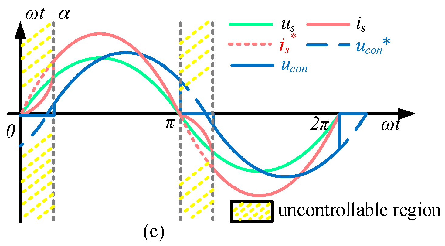
ψ. The unidirectional power transmission characteristics of the bridgeless modules will cause serious distortion in the period between the zero-crossing point of the input current
is and the zero-crossing point of the
ucon [
23]. To make the bridgeless modules input current not distorted, the best way is to make
in phase with
Is*as shown in
Figure 3b [
21,
23]. In this case, bridgeless modules cannot provide the required reactive power of inductor
L [
22]. Moreover, it will be fully undertaken by the H-bridge modules. In the case of the AC-side reference voltage of the H-bridge module reaches its maximum value. However, the desired reactive power consumed by
L that the H-bridge module should provide is not reached, the remaining reactive power consumed by
L must be provided by the bridgeless module. In this case, the steady-state AC-side phasor diagram changes to
Figure 3a. From the aforementioned analysis, input current will be distorted as shown in
Figure 3c. Especially when injecting reactive power from the power grid, this distortion will greatly increase. Moreover, the adjustable power factor angle range that hybrid cascaded rectifier operation mode can provide will be limited. It is therefore important to calculate the adjustable power factor angle range to provide a basis for switching to the hybrid cascaded rectifier operation mode when the open-circuit fault happens.
4. Analysis of Adjustable Power Factor Angle in the Hybrid Cascaded Rectifier Operation Mode
In the hybrid cascaded rectifier operation mode,
is always kept in phase with
Is* to provide the active power required by DC-side loads, and the H-bridge modules provide the reactive power required by the AC-side and the active power required by the DC-side loads simultaneously. The AC-side phasor diagrams under lagging power factor and leading power factor are shown in
Figure 4. The voltage across the input inductor
UL is orthogonal to
Is and the AC-side reference voltage
is lagging
Us than
φ. In the case of lagging power factor,
φ <
θ and
φ ≥
θ may occur according to the different power, voltage level and power factor. The input current
Is* is lagging grid voltage
Us than
θ. On the condition of leading power factor, the input current
Is* is leading grid voltage
Us than
θ. The following relationships exist:
where
(
i = 1, ...,
m) and
(
j =
m + 1, ...
m +
n) are the AC-side reference voltage for each bridgeless module and H-bridge module, respectively.
Each module’s DC-side output voltage is
Udc. The maximum output voltages
Uconmax in rms of each cascaded module can be expressed as [
24,
26]:
Assuming the bridgeless modules can provide rms of the maximum AC-side reference voltage. the step-up ratio
k is defined as:
Considering that the DC-side voltages can be balanced in steady-state, the input current is derived by:
Base on the analysis of
Section 3. The AC-side voltage of the
n H-bridge modules
should not exceed the maximum total AC-side reference voltage, which can be expressed as:
In the case of
φ <
θ of lagging power factor operation, applying geometric relationship in ∆
HPC yields:
Substituting Equation (2), (3), (4), and (6) into (5) yields:
On the condition of
φ ≥
θ of lagging power factor operation, applying the geometric relationship in ∆
HDC yields:
Due to the AC-side voltage of
n H-bridge modules
satisfies (5), Substituting (3), (4), and (8) into (5) yields:
In the case of leading power factor operation, hybrid cascaded rectifier’s AC-side reference voltage
can be expressed as:
where the rms value of
and the corresponding lagging angle
φ are derived by:
Applying the law of cosines in Δ
OHC, the AC-side reference voltage of the
n H-bridge modules
can be expressed as:
Substituting (3), (4), (11) and (12) into (5) yield:
Equation (7), (9) and (13) shows that the adjustable lagging power factor angle and leading power factor angle θ is related to the step-up ratio k, inductance L and load resistance Ri and Rj. In most cases, the voltage drop on the boost inductor is usually small, so φ < θ is the common lagging power factor operation mode. By drawing the curve of the left Equation of (7) and (13) versus power factor angle θ and the curve of the right Equation of (7) and (13), respectively, the intersection point is the maximum lagging power factor angle θlag_acmax and the maximum leading power factor angle θlead_acmax that this hybrid cascaded rectifier operation mode can operate. In this case, the adjustable lagging power factor angle range and the adjustable leading power factor angle range are (0, θlag_acmax) and (θlead_acmax, 0), respectively.
The adjustable power factor angle of the hybrid cascaded rectifier operation mode is not only affected by whether the AC-side voltage of the H-bridge modules can reach the maximum value which has been analyzed above, but also by the limit of the rated power
S of the cascaded H-bridge rectifier. Then the maximum adjustable power factor angle can be expressed as:
where
P is the active power of the cascaded H-bridge rectifier. The adjustable lagging power factor angle range and the adjustable leading power factor angle range are (0,
θra_max) and (−
θra_max, 0), respectively. Based on the above-mentioned two qualifications, the adjustable lagging power factor angle range is the interaction between the set of (0,
θra_max) and (0,
θlag_acmax). Moreover, the adjustable leading power factor angle range is the interaction between the set of (−
θra_max, 0) and (−
θlead_acmax, 0).
For example, based on the parameters presented in
Table 2,
Figure 5 depicts the curves of AC-side voltage of the H-bridge modules
at different power factor angle
θ with the various number of bridgeless modules
m and H-bridge modules
n under the same step-up ratio
k or with various step-up ratio
k under the same number of bridgeless modules
m and H-bridge modules
n in the lagging power factor operation and leading power factor operation. The solid line shows the left Equation of (7) and (13) versus
θ. The dotted line depicts the right Equation of (7) and (13) versus
θ. The intersection points (K, S, T, U, W, X, Y, Z) between the solid line and the dotted line is the maximum power factor angle that this hybrid cascaded rectifier operation mode can operate. Considering the limit of the rated power, the adjustable lagging power factor angle range and the adjustable leading power factor angle range are (0, 58°) and (−58°, 0°), respectively. The calculation results corresponding to
Figure 5 and the final adjustable lagging power factor angle range and the final adjustable leading power factor angle range when considering the rated power restriction are shown in
Table 3. Based on the above analysis, when the total number of cascaded modules is determined, the adjustable lagging power factor angle range and the adjustable leading power factor angle range that the hybrid cascaded rectifier operation mode can operate will increase with the increase of the number of H-bridge modules
n or with the decrease of the step-up ratio
k.
5. Control Strategy
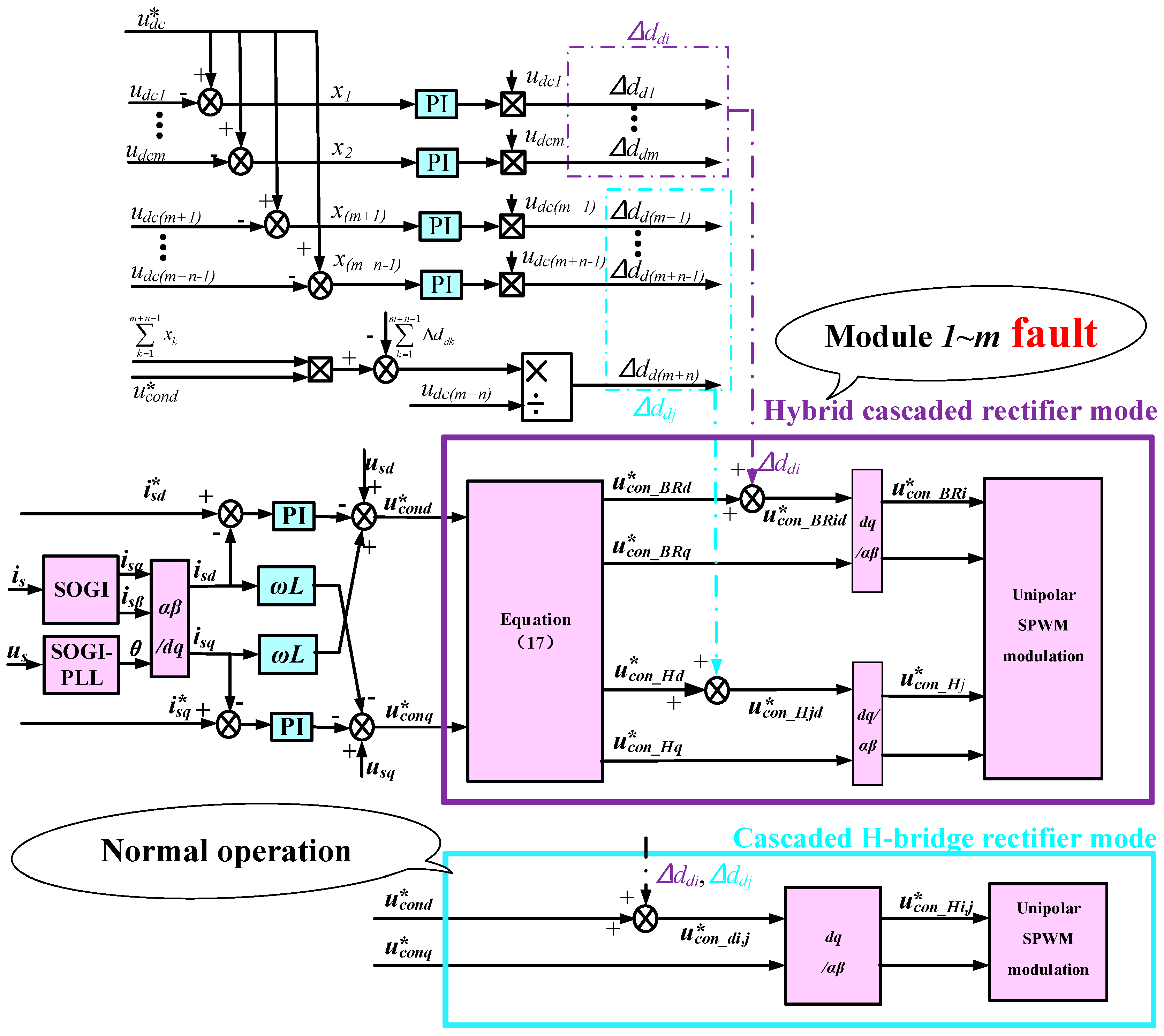
The multifunctional rectifier operates in the hybrid cascaded rectifier mode when one or two switches are faulty while it operates normally when there is no fault. The voltage and current double closed-loop control strategy can be used to achieve the control strategy. The active current reference
in the current loop is derived by (15).
where
KiP and
KiI are the proportional coefficient and Integral coefficient, respectively. The reactive current reference
depends on the desired reactive power. In this case, the power factor angle
θ can also be defined as:
By adopting the dq decoupling control, the active component and reactive component of the total AC-side reference voltage of the multifunctional cascaded rectifier, i.e.,
and
, are obtained. In the case of the hybrid cascaded rectifier mode,
needs to be always in phase with
is to avoid input current zero-crossing distortion. The AC-side reference voltage of bridgeless modules
and
, as well as the AC-side reference voltage of the H-bridge modules
and
can be expressed as:
If the system is unbalanced, the total input active power should be redistributed according to the different active power required by each bridgeless module and H-bridge module. The active-duty cycle should be modified by adding the voltage balance controller [
26]. Then the new AC-side reference voltage of bridgeless module
, as well as the new AC-side reference voltage of H-bridge module
can be expressed as:
where ∆
ddi (
i = 1
,...,m)
and ∆
ddj (
j =
m + 1
,...,m + n) are the active regulation component and the reactive regulation component of duty cycles for the bridgeless modules and the H-bridge modules, respectively. By employing
m +
n inverse dq transformations, the final AC-side reference voltages,
and
, can be obtained. In the case of normal operation and when the system is unbalanced, the AC-side reference voltage
(
k = 1, ...,
m +
n) for the cascaded H-bridge rectifier module is the sum of
and ∆
ddi and the sum of
and ∆
ddj. By employing
m +
n single-phase inverse dq transformations, the final AC-side reference voltages
can be obtained. Then the unipolar modulation is adopted for the multifunctional cascaded H-bridge rectifier. This is because it possesses the merit of smaller switching loss and lower DC voltage ripple compared with bipolar modulation [
27]. The control diagram of the multifunctional cascaded H-bridge rectifier under normal operation and the faulty condition is shown in
Figure 6.
6. Experiment Results
An experimental platform as shown in
Figure 7 was established; its specifications are shown in
Table 4. In the experimental tests, Modules 1 and 2 worked in bridgeless mode, while Module 3 works in H-bridge mode. REN-DSP28335 is selected as the core controller. First, considering the limit of rated power, the adjustable lagging and leading power factor angle range were 0°–58° and −58°–0°, respectively. Then it was essential to verify the calculated maximum power factor angle range when the cascaded H-bridge rectifier operated in the hybrid cascaded rectifier mode. Based on the analysis in
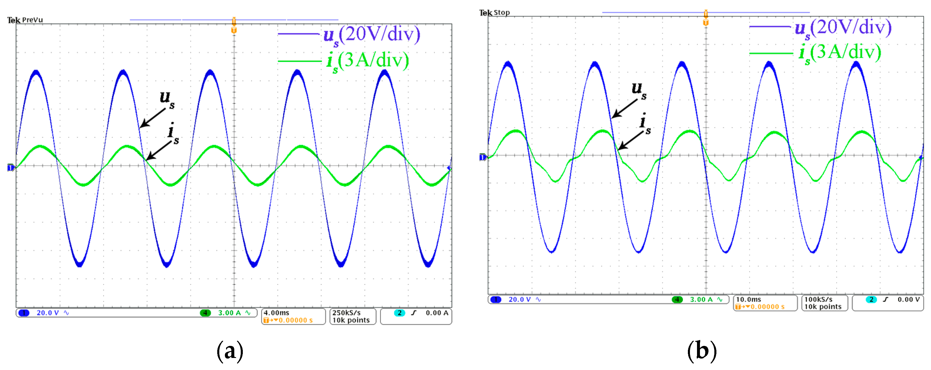
Section 4, the adjustable lagging and leading power factor angle at which the hybrid cascaded rectifier operation mode could theoretically operate was 0°–25° and −27°–0°, respectively, which were in the range of the adjustable power factor angle ranges when considering the rated power. On the condition of the lagging power factor angle of the hybrid cascaded rectifier operation mode was 18°,
Figure 8a shows that the input current was sinusoidal and showing a satisfactory current quality. However, when the lagging power factor angle of the hybrid cascaded rectifier operation mode beyond the range of the adjustable power factor angle and was set as 35°,
Figure 8b shows that the input current becomes seriously distorted, which means this hybrid cascaded rectifier operation mode cannot provide such a large reactive power. In the case of the leading power factor angle of the hybrid cascaded rectifier operation mode was −24°,
Figure 9a shows that the input current was sinusoidal and showing a satisfactory current quality. However, when the leading power factor angle of the hybrid cascaded rectifier operation mode beyond the range of the adjustable power factor angle that the hybrid cascaded rectifier operation mode could operate and was set as -36°,
Figure 9b shows that the input current becomes distorted seriously, which means this rectifier cannot provide such a large reactive power. It is evident in
Figure 8;
Figure 9 that the input current was approximately sinusoidal within the range of the calculated adjustable power factor angle while the input current was seriously distorted beyond the calculated adjustable power factor angle in the hybrid cascaded rectifier operation mode.
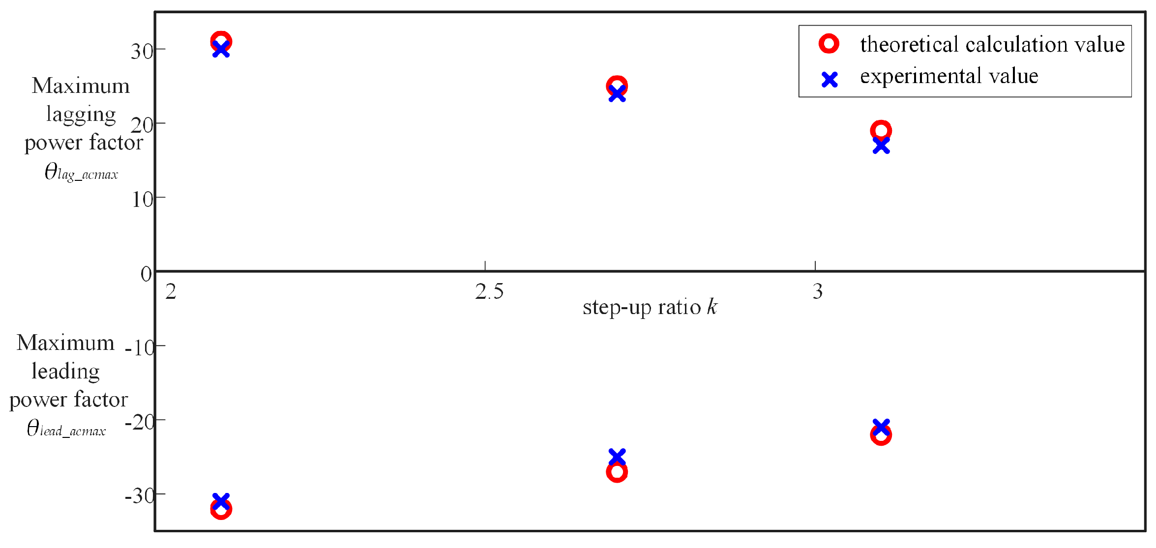
Figure 10 shows the maximum adjustable power factor comparison between the theoretical calculation values and experimental values under different step-up ratio
k. It can be seen in
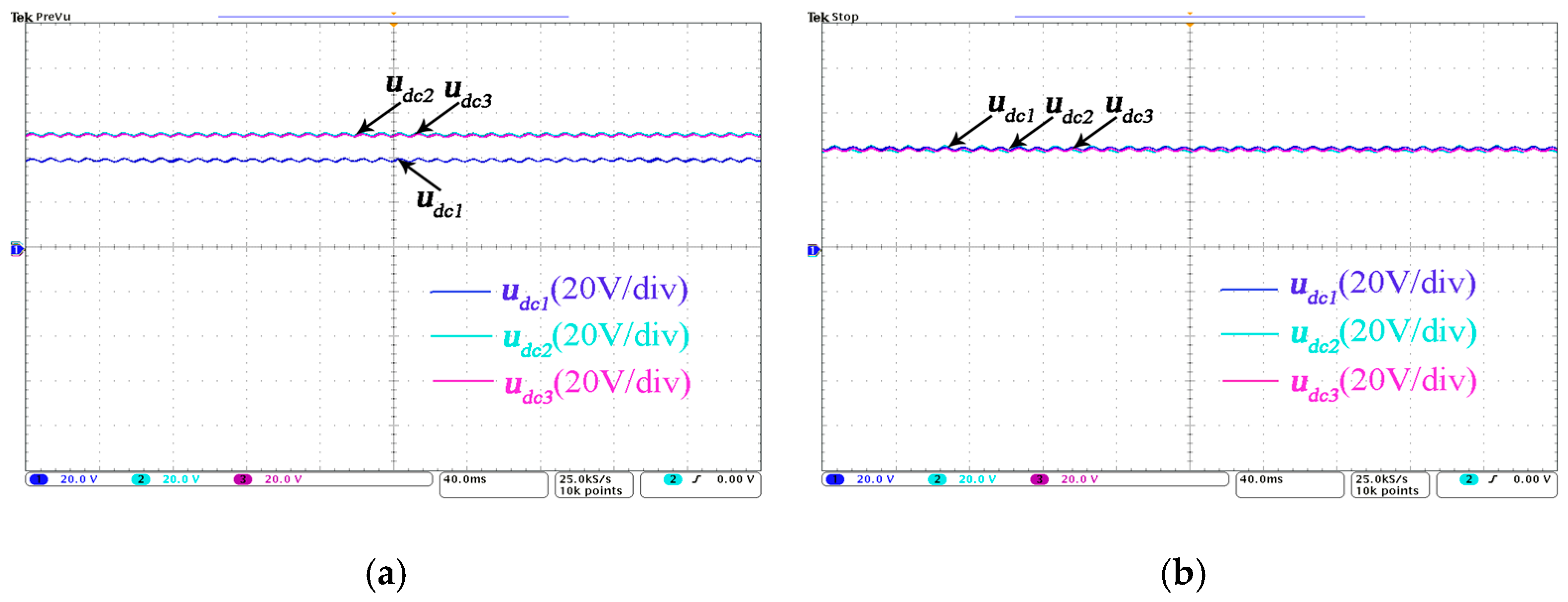
Figure 10 that the experimental values were close to the theoretical calculation values. The waveforms of the DC-side voltage are shown in
Figure 11. It is clear that under the voltage balance control presented in this paper, all the DC voltages were balanced, which proves the feasibility of the presented method.


