Article

Real Time-Based under Frequency Control and Energy Management of Microgrids

by
Muhammed Y. Worku
1,*,
Mohamed A. Hassan
1 and
Mohamed A. Abido
2,3
1
Center for Engineering Research, Research Institute, King Fahd University of Petroleum and Minerals, Dhahran 31261, Saudi Arabia
2
Electrical Engineering Department, King Fahd University of Petroleum and Minerals, Dhahran 31261, Saudi Arabia
3
Senior Researcher at K. A. CARE Energy Research & Innovation Center, Dhahran 31261, Saudi Arabia
*
Author to whom correspondence should be addressed.
Electronics 2020, 9(9), 1487; https://doi.org/10.3390/electronics9091487
Submission received: 16 August 2020 / Revised: 4 September 2020 / Accepted: 8 September 2020 / Published: 10 September 2020
(This article belongs to the Special Issue Emerging Technologies in Power Systems)

Abstract

:
In this paper, an efficient under frequency control and the energy management of a distributed energy resources (DERs)-based microgrid is presented. The microgrid is composed of a photovoltaic (PV), double-fed induction generator (DFIG)-based wind and diesel generator with critical and non-critical loads. The system model and the control strategy are developed in a real time digital simulator (RTDS). The coordination and power management of the DERs in both grid-connected and islanded operation modes are implemented. During power imbalances and frequency fluctuations caused by fault or islanding, an advanced automatic load shedding control is implemented to regulate and maintain the microgrid frequency at its rated value. One distinct feature implemented for the load shedding operation is that highly unbalanced critical loads are connected to the microgrid. The diesel generator provides the required inertia in the islanded mode to maintain the microgrid rated frequency by operating in the isochronous mode. The International Council on Large Electric Systems (CIGRE) medium voltage (MV) test bench system is used to implement the DERs and their controller. The proposed control approach has potential applications for the complete operation of microgrids by properly controlling the power, voltage and frequency in both grid-connected and island modes. The real time digital simulator results verify the effectiveness and superiority of the proposed control scheme in grid connected, island and fault conditions.

1. Introduction

A small-scale power grid with distributed storage, distributed generation (DG) and loads connected to each other with a clear electrical boundary is a microgrid [1,2]. Microgrids are operated either in grid connected mode where power is exchanged with the main grid based on demand and supply [3,4], or in islanded mode where the microgrid acts as a power hub supplying the loads connected to it [5,6]. In 2011, IEEE approved a standard called IEEE 1547.4-2011 that will guide the design and operation of islanded systems with a high penetration of DG when integrated with the main electric power system [7]. A microgrid control must regulate the power, voltage, and frequency when in grid-connected or islanded operation within specified thresholds of power quality and reliability.
Microgrid control structures are classified as centralized and decentralized. In the centralized microgrid control, the central control unit coordinates the microgrid control and protection functions by sending operating commands to the local control units and circuit breakers [8,9]. In the decentralized microgrid control structures, each component is independently controlled by its local control unit, and does not coordinate with other local control units [10,11]. Typically, due to the widespread topology of power system networks and electrical coupling between power system components, microgrid implementations are a combination of centralized and decentralized control structures. A significant challenge to microgrid implementation is the stable control of voltage and frequency during grid-connected and islanded operation modes.
On the other hand, microgrid control should switch from grid-connected mode to autonomous mode with minimum voltage and frequency fluctuations. Managing the power balance between supply and demand is one of the most important evaluating criteria for the successful operation of the microgrid in both operating modes. The utility grid maintains the balance in the grid-connected mode [12,13], whereas, in the islanded mode, the microgrid has to do this, either by increasing generation or load shedding [14,15]. Load shedding schemes must be designed for cases where the power available from the distributed energy resources (DERs) is insufficient to supply the loads in the islanded microgrid [16,17]. Load shedding control should operate rapidly to restore the power balance in the microgrid to avoid voltage and frequency collapse [18,19,20,21]. Energy management of hybrid energy systems consisting of battery energy storage system is presented in [22,23]. The authors proposed a controller to ensure thermal safety and the reduction of overall driving cost. A review of the methods used to optimize the uncertainties involved in renewable sources such as wind and photovoltaic (PV) and the optimal power flow of those sources with energy storage is discussed in [24,25].
To cope with potential power deficits caused by microgrid islanding, a two-stage load shedding scheme is presented in [26]. However, the research focused on the curtailments of the loads in each stage and the impact of fault in island mode was not addressed. Adaptive distribution state estimator based under frequency load shedding controller is addressed in [27]. However, the distribution state estimator requires costly measuring devices which are uneconomical for practical applications. The authors in [28] proposed a controller to regulate frequency and bus voltages simultaneously within the permissible values, using load shedding schemes considering power and power factor of various load types. However, inverter based autonomous microgrids have low effective inertia and fail to regulate the frequency under severe fault conditions. A Monte Carlo simulation to continuously monitor load flow for the verification of the frequency and the voltage of all buses to design a global and local strategies of load shedding is presented in [29]. However, the authors focused only on the steady state analysis, and the transient response of the microgrid from grid connected to island mode was not addressed. Under voltage-frequency load shedding strategy using four variable/dimensional (4D) piecewise linear curves to determine the proper load shedding location and amount of load rejection in multi-bus microgrids is proposed in [30]. However, the communication protocol required for the proposed controller hinders it from practically implementation.
The load shedding operation in the islanded mode and the microgrid transient response during islanding have not been extensively studied in the previous research. In this paper, an efficient automatic load shedding control strategy for microgrids supplying critical and non-critical loads is proposed and implemented. The microgrid is based on PV, doubly fed induction generator (DFIG) based wind system and a diesel generator. The PV and the DFIG based wind sources are interfaced to the point of common coupling (PCC), using a voltage source converter (VSC) with decoupled d–q current control strategy. The main contributions of the paper are:
  • The coordination and power management between DERs during grid-connected and island modes is addressed.
  • During intentional islanding or fault, with insufficient DER power, an automatic under frequency load shedding is activated to disconnect the non-critical loads until the system frequency is restored.
  • The transient and load shedding operation under highly unbalanced loads connected to the microgrid is also investigated.
  • In island mode of operation, the DERs supply the loads and a controller is proposed and implemented for the diesel generator to control the frequency in isochronous mode, by maintaining a constant speed regardless of the load.
The rest of the paper is organized as follows. The proposed microgrid system structure is presented in Section 2. Section 3 describes the proposed controller. Results and discussions are presented in Section 4, while Section 5 concludes the paper.

2. System Configuration

The microgrid structure consisting of three DERs of PV, diesel generator and DFIG based wind system is shown in Figure 1. The eleven bus CIGRE medium voltage (MV) benchmark test system [31] is used for this study. However, due to the real time digital simulator (RTDS) node limitation, the system is reduced to seven bus, while maintaining the original structure. The 13.2 kV microgrid is connected to the 138 kV utility grid through a 138 kV/13.2 kV transformer. The point of common coupling (PCC) is at Bus 1 on the LV side of the transformer, and the microgrid is interconnected using a static switch (S1). The 5.5 MVA diesel generator is connected to the microgrid at Bus 7 and performs the frequency and voltage control of the microgrid during the islanded operation. The 1.74 MW PV system is connected to the microgrid at Bus 3 and the 2 MW DFIG wind turbine generator is connected to Bus 5. The total balanced and unbalanced loads connected to the microgrid are provided in Table 1 and Table 2 respectively. The PV and DFIG sources are interfaced to their corresponding buses using voltage source converters (VSC) with decoupled d–q current control strategy.
Dynamic models of the main components of the microgrid were developed using RSCAD. Under normal operation, the static switch S1 is closed and the microgrid and the main grid operate in parallel supplying the loads together. The grid maintains the voltage and frequency at their corresponding rated values. In the islanded mode, the DERs supply the loads, and if the generated power from the DERs is insufficient to supply the loads or during fault events, an automatic load shedding control is activated to regulate the frequency to its nominal rated value by removing the non-critical loads. In this operating mode, the frequency is controlled and maintained at the rated 60 Hz by the diesel generator in isochronous mode, by keeping the original speed set point after a disturbance.

3. Proposed Control Scheme

Each DER is equipped with its own proposed and implemented controller. The DERs supply constant P–Q during grid connected mode, however, during islanded mode, the diesel generator maintains the system voltage and frequency at the rated nominal value. The details of the PV control can be found in [12]. The proposed controller for each component of the microgrid described in Section 2 and the load shedding scheme is provided in Section 3.1, Section 3.2 and Section 3.3.

3.1. Diesel Generator Model and Control

Diesel generators are used as backup power supply during power outages, or to generate power in off-grid applications, such as in remote locations or on large ships. Diesel generators are also used to control voltage, frequency and load regulation.
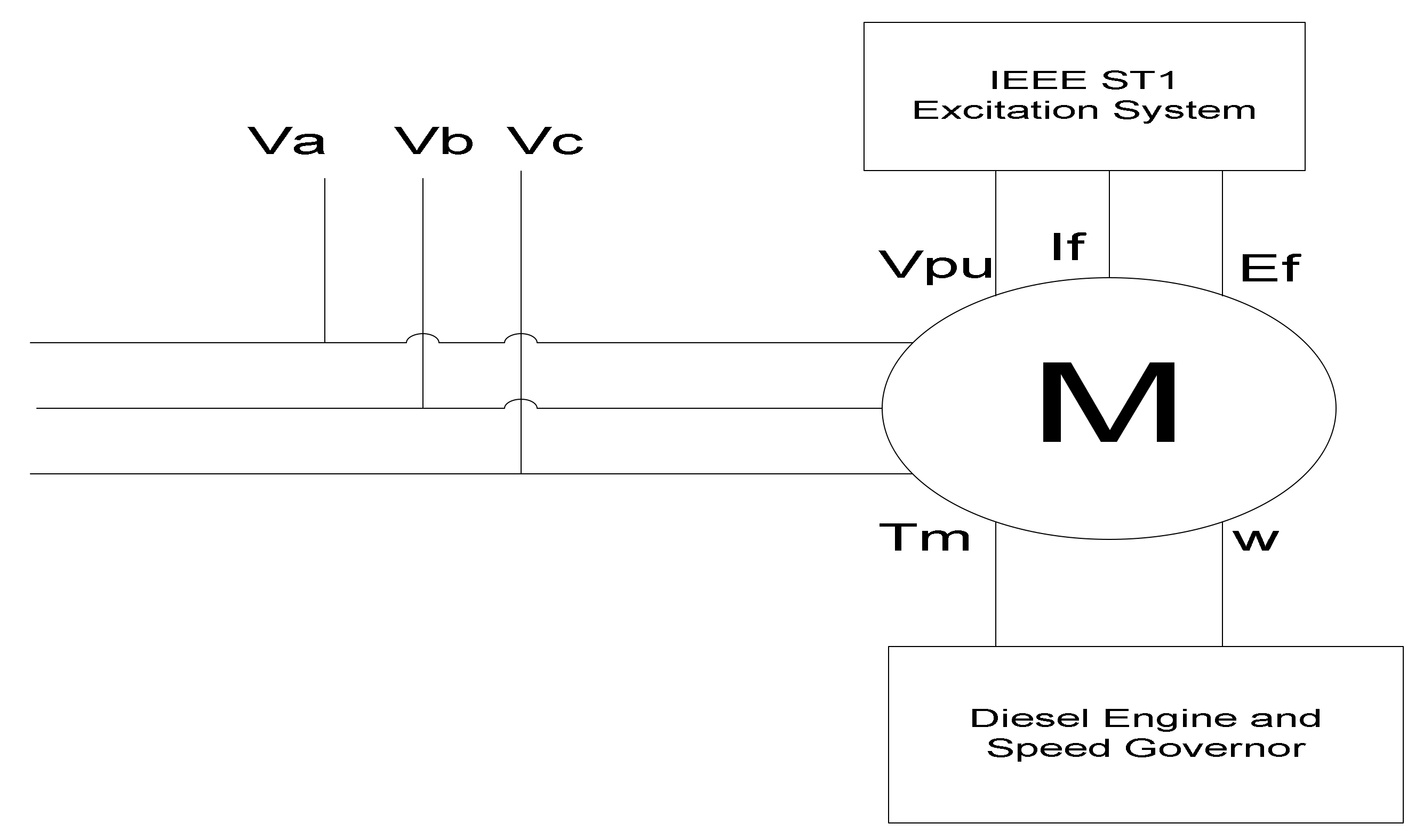
Currently, most microgrid implementations rely on diesel generating systems. Although diesel generators are not environmentally friendly, they are vital in controlling the microgrd frequency, as they provide the required inertia in the islanded mode by operating in the isochronous mode. The diesel generator used in this paper has two roles: firstly, it controls the frequency of the microgrid in the islanded operation, and secondly, it provides real and reactive power in both grid-connected and islanded operations. Figure 2 depicts the diesel generator M and is represented in the simulation by a synchronous machine. The diesel generator is controlled by the excitation system and the speed governor. The speed governor driven by a diesel engine regulates the machine frequency. Figure 3 presents the diesel generator and speed governor controller. The input parameters to Figure 3 are the speed reference ωref and the diesel generator speed ω both in pu, and the output is the mechanical torque Tpu. The diesel generator operates in speed-droop mode and supplies a preset reference power at the grid frequency in grid-connected operation, and in islanded operation, it maintains a constant frequency, irrespective of the load by operating in isochronous mode. The switch in Figure 3 is to select the operation of the diesel generator in island mode or grid connected mode.

3.2. Doubly Fed Induction Generator (DFIG) Model and Control

The doubly fed induction generator is used to convert the wind turbine’s mechanical power to electrical power. The output power generated from a horizontal axis wind turbine is given by:
P m = 0.5 C p ρ A V 3
where, Cp is power coefficient, ρ is the density of air, A is the swept area and V is the wind velocity. Cp is a function of the tip speed ratio λ and the blade pitch angle β, which is the angle between the wind speed direction and the surface of the wind turbine blades [32].
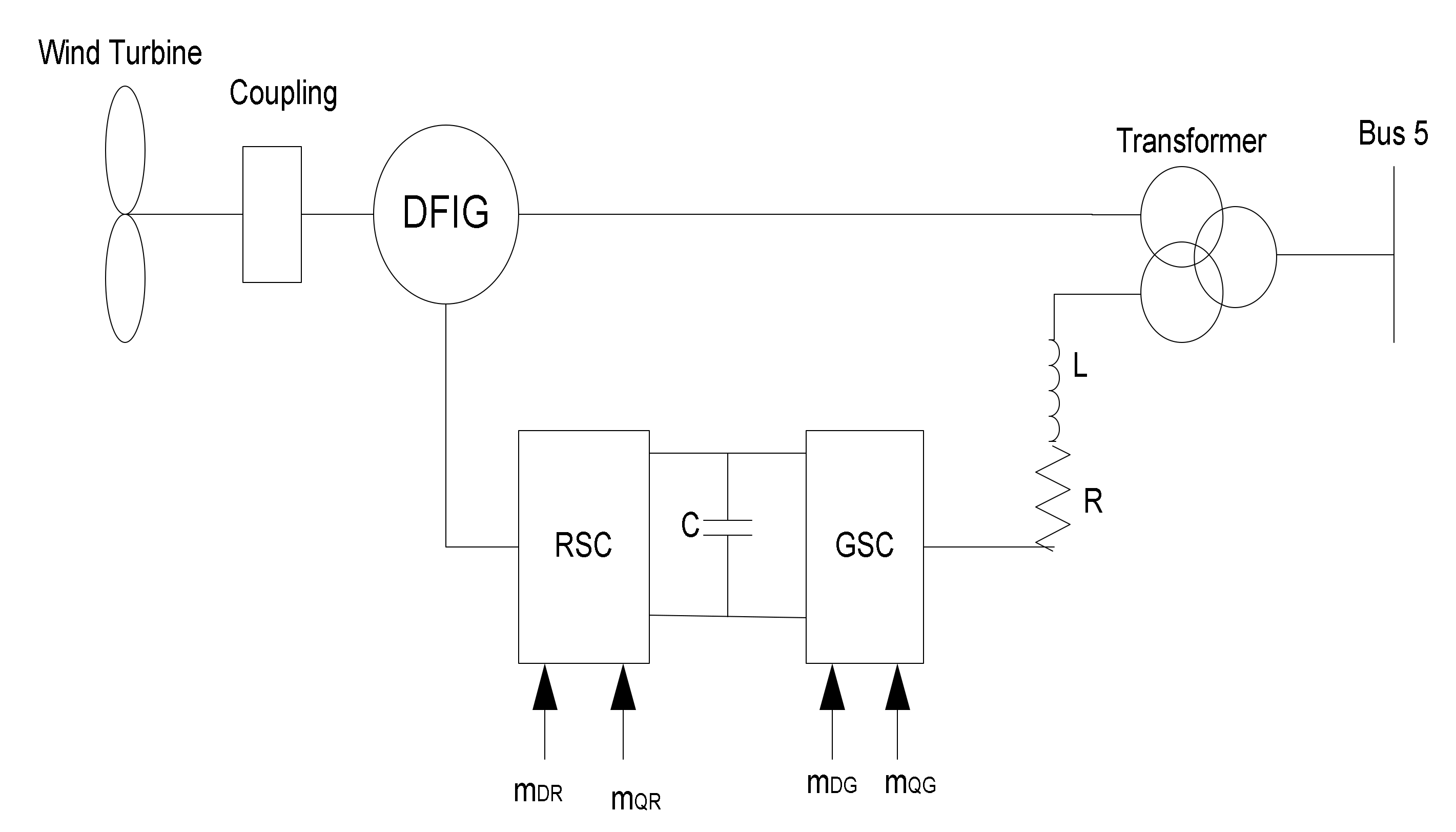
Figure 4 shows a wind turbine system based on DFIG, where its stator is directly connected to the grid through a transformer and its rotor is interfaced to the grid using two power converters connected back to back with a common DC link voltage. The DFIG allows variable speed operation over a slip speed range (typically 0.7–1.2 pu), and has better controllability than other wind turbine generators, without the need for additional mechanical parts and capacitors for reactive power compensation. To limit the generated power from the wind turbine above the rated wind speed, pitch angle control is implemented.
For wind speeds between the cut-in speed Vc and rated speed Vr range, the pitch angle is set to zero, and a maximum power point tracking (MPPT) control strategy is used to track the maximum power of the wind turbine at the given wind speed. Commonly used MPPT methods are optimal tip speed ratio, where the optimum rotor speed for a given wind speed is calculated based on the known optimum tip speed ratio. The turbine power feedback control measures the rotor speed at a given wind speed, and calculates the maximum power from the known power curve of the wind turbine. The optimal torque control, which uses the idea that for a given gearbox ratio, the turbine’s mechanical torque and speed can be converted to the generator torque and speed from which the optimum torque can be calculated using the generator rated parameters, is presented in Equations (2)–(5).
P m , m a x = k o p t ω m , o p t 3
T m , m a x = k o p t ω m , o p t 2
ω m , o p t = λ o p t V R
k o p t = 0.5 π ρ C p R 5 λ o p t 3
where Pm,max is the maximum power, kopt is the optimum power coefficient, ωm,opt is the optimum turbine speed, Tm,max is the maximum torque.
The optimum torque control (OTC) is calculated from Equation (3) and shown in Figure 5, implemented in this work. The input to the torque control presented in Figure 5 is the turbine speed, ωrpu, and the output is the electrical torque reference, Te_REF, that indicates the maximum power in the wind.

3.2.1. Grid Side Converter (GSC) Control

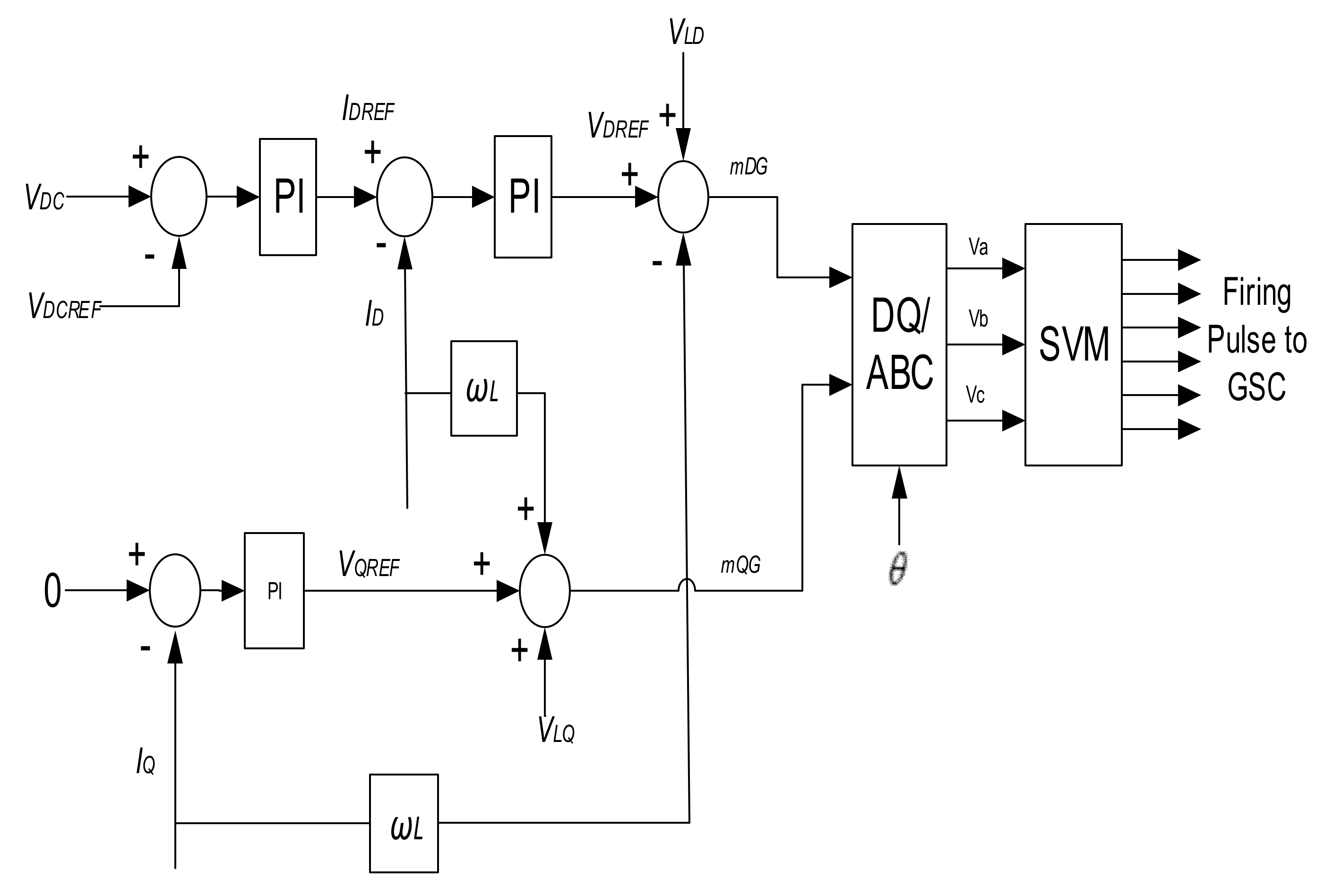
The two functions of the GSC are; to provide a reactive power support to the grid voltage at the PCC, and to control the DC link voltage to a constant reference value. The decoupled d–q current mode control is used for the GSC to allow the independent control of the DC link voltage and reactive power injected to the grid during fault events. The d axis control regulates the DC bus voltage to a constant reference voltage VDCREF, whereas the reactive power and consequently the power factor of the DFIG system is controlled by the q axis current controller. The reactive power reference QREFG is set to zero for unity power factor. Figure 6 shows the decoupled current control implemented for the GSC.
Where VDC is the DC link voltage, VDCREF is the reference DC link voltage, ω is the angular frequency, L is the line inductance, VLD is d-axis GSC voltage, VLQ is q-axis GSC voltage. The voltage control signals mDG and mDQ are then converted back using dq/abc and firing pulses are generated for the GSC.

3.2.2. Rotor Side Converter (RSC) Control

The function of the RSC is to control the electrical torque and power factor of the DFIG, which respectively controls the real and reactive power exchanged between the rotor and the grid. The equations that describe the relationship between the electrical torque, Te in the d–q reference axis is given by:
T e = 1.5 P L m i m s i q r
where Lm is the magnetizing inductance; ims is the stator magnetizing current; iqr is the q axis rotor current; P is the number of poles. The rotor phase currents are transformed to the d–q axis using the slip angle θslip which is the angle between the stator flux vector θs and the rotor angle θr. Figure 7 provides the RSC control. ωslip is the slip frequency; ωs, ωr are the stator and rotor angular frequencies.
IDR_REF is set to zero to minimize the power losses in the VSC and rotor circuit. IQR_REF is determined from the torque equation given by:
T e , R E F = 1.5 P L m i m s I Q R , R E F
I Q R , R E F = T e , R E F 1.5 P L m i m s
Te,REF is obtained using the optimum torque MPPT control shown in Figure 5. The output of the RSC current control mDR, and mQR rotor voltage references are used to create the rotor modulation waveforms to generate the switching sequence for the RSC. The details of the DFIG control can be found in [33].

3.3. Load Shedding Scheme

When the microgrid is islanded or during a fault in island mode, a frequency fluctuation arises due to the power unbalance between the load and available generation from the DERs. In order to prevent the frequency collapse, the microgrid should be equipped with a fast and automatic load shedding scheme. The two vastly used load shedding techniques are static and dynamic schemes [34,35]. However, the most common practical load shedding scheme is the static one, and hence an advanced static load shedding scheme is implemented in this work. Four main steps are involved in designing a static load shedding scheme. The first step is to calculate the amount of load to be shed, while the second step involves in determining the load shedding stages with their corresponding load size to be shed at each stage. The third step involves in setting the thresholds for the frequency and rate of change of frequency, while the last step sets the time delay. The priority of non-critical loads is assigned at the design stage, considering the loads relative importance and the normal loading. If the load needs continuous power supply, it will be assigned as a critical load. Loads assigned as critical will not be shedded, irrespective of the microgrid operation mode. In practical systems, time delayed back up relays are provided at each stage of the load shedding scheme to avoid system collapse due to slow frequency drifts.
The load shedding stages, amount of load to be shed, the frequency and rate of change of frequency limits and time duration settings are shown in Table 3. Figure 8 depicts the automatic load shedding logic implemented in RTDS, where the inputs are both frequency and rate of change of frequency (ROCOF). The load assigned the first priority will be tripped by the controller when the frequency goes below a preset value, and if the rate of change of frequency is more than a pre-set value. If the frequency drops more, the loads assigned to the next priority will be removed, and this continues until the nominal microgrid frequency is attained. Loads connected to Bus 1–4 provided in Table 1 are non-critical loads and are modeled as switched RL passive loads, which are allowed to shed if needed, while Table 2 provides the unbalanced loads located on Bus 5–7 and are modeled as non-switchable dynamic loads representing the critical loads in the network. The proposed method is economically feasible for practical implementation, as the materials required, such as relays, timers and switches are easily available in the market. The proposed control approach does not need a dedicated communication channel that is costly for power system owners to implement.

4. Results and Discussion

The microgrid shown in Figure 1 is implemented in RSCAD. In grid-connected mode, the main switch S1 is closed and the microgrid frequency is determined by the grid. The loads connected to the microgrid in this mode are supplied by both the gird and DERs. The DFIG based wind and PV systems control their real and reactive power output using the control schemes described in Section 3, while the diesel generator operates in droop control to exchange real and reactive power with the grid. The diesel generator has been set to produce 3 MW and 1.74 MVar, whereas the PV and wind operate as a constant P–Q source at unity power factor and rated power of 1.74 MW and 2 MW, respectively. The DERs generated a total active power of 6.74 MW, and the total load connected to the microgrid was around 7.2 MW. Since the power generated from the DERs is insufficient for the loads, the remaining power of the loads and the transmission line losses comes from the main grid.
To demonstrate the effectiveness of the proposed controllers, the following tests have been applied.
(A)
Grid-connected to islanded mode switching
(B)
Load shedding control during fault in islanded mode

4.1. Grid-Connected to Islanded Mode Switching

In grid connected mode, the diesel generator operates in droop control to exchange real and reactive power with the grid, and the grid controls the voltage and frequency. Opening the circuit breaker switch S1 makes the microgrid in islanded mode of operation. In island mode, the diesel generator operates in the isochronous mode. In this mode, the generator maintains a constant speed and hence frequency, regardless of the load (from no-load to full load).
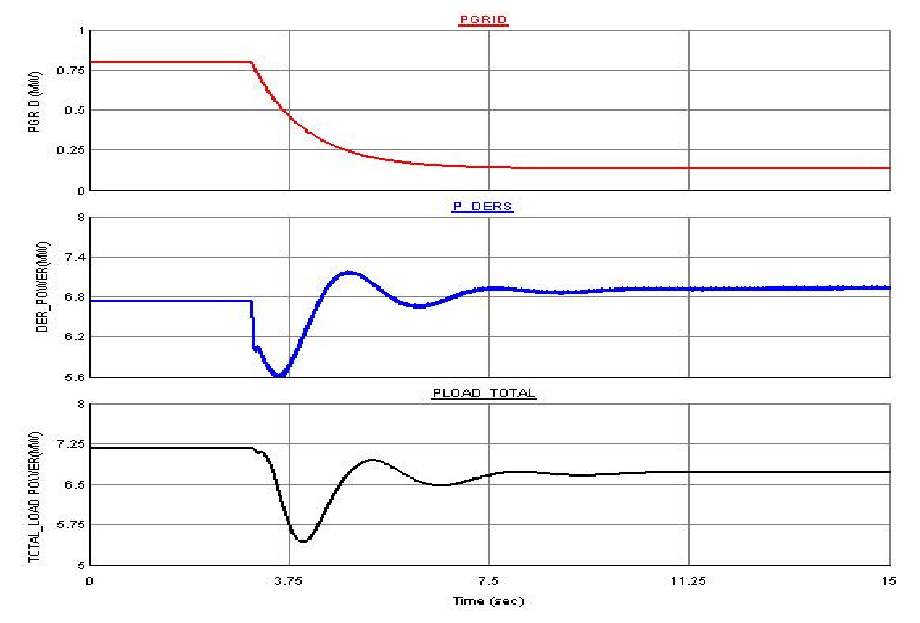
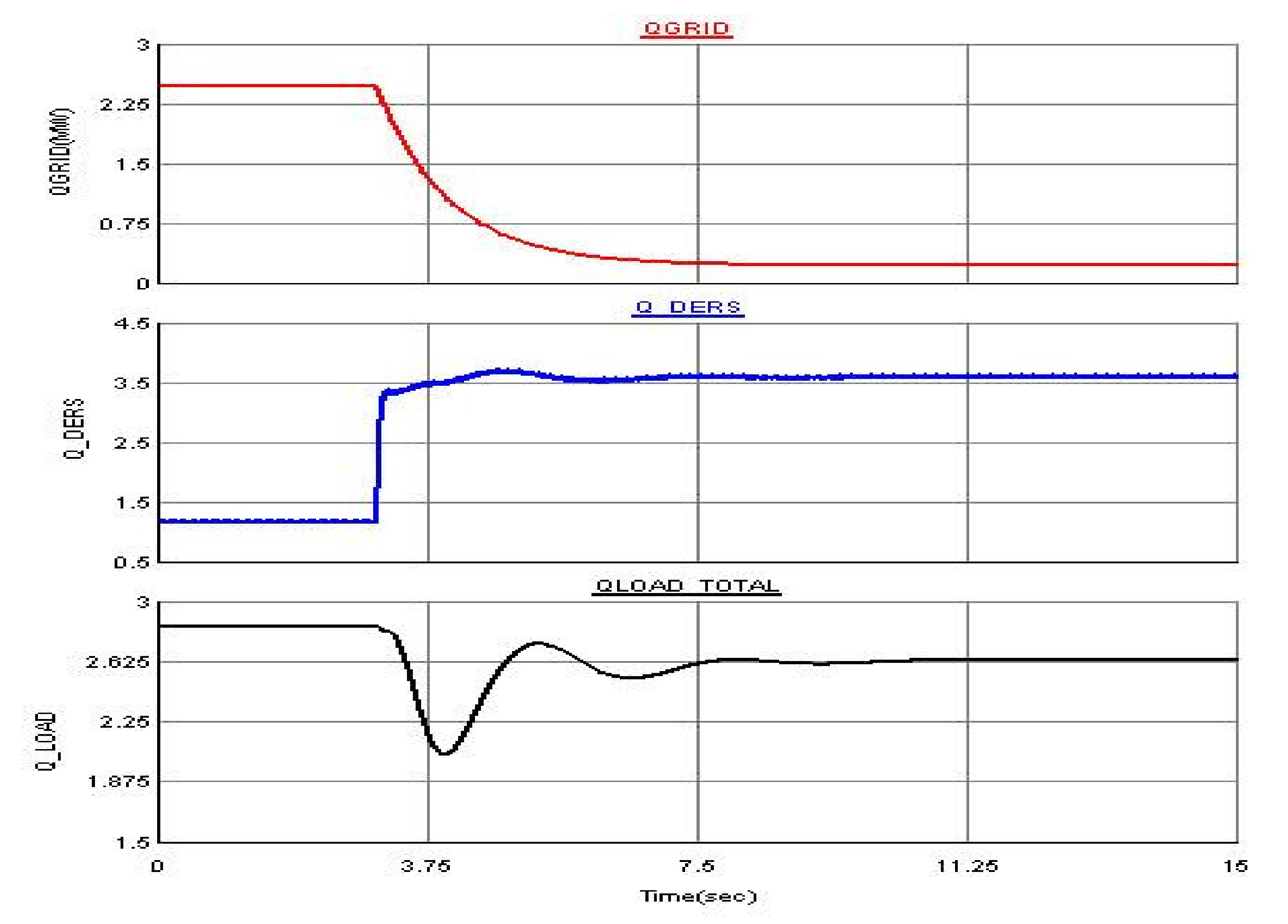
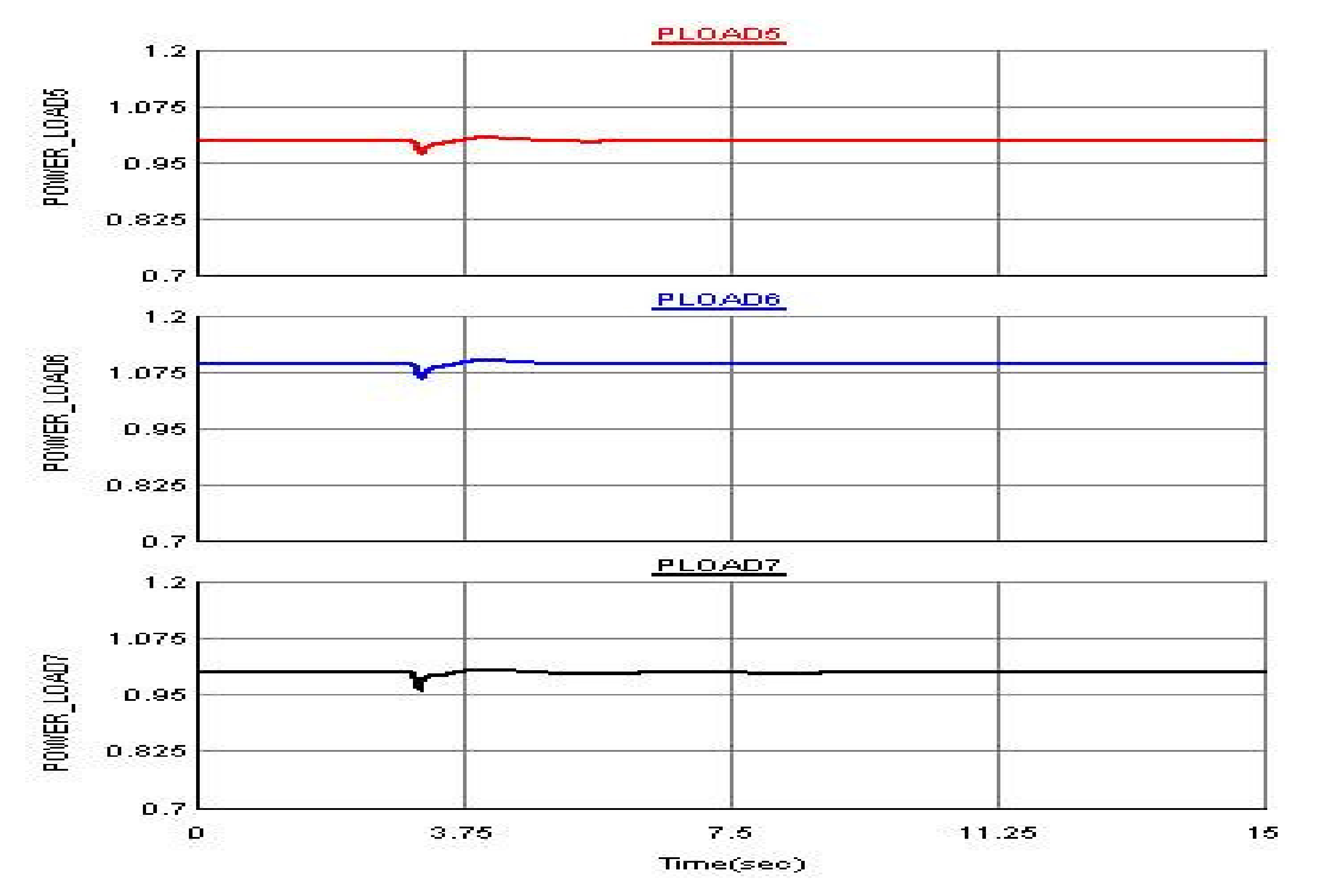
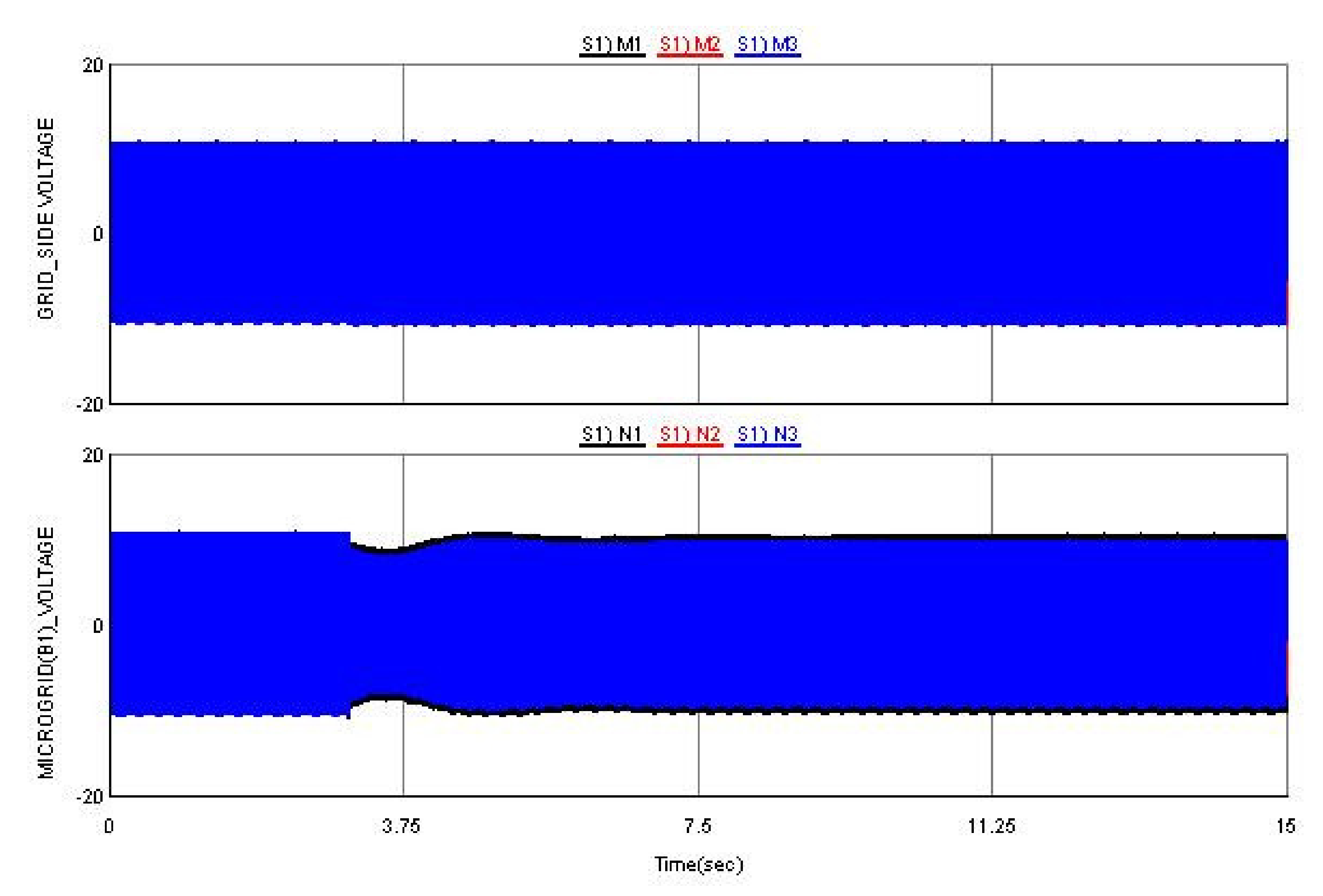
Once the grid is disconnected, both voltage and frequency deviate due to excessive loading on the DERs. Shown in Figure 9 is the frequency before and after the microgrid is islanded. The load shedding control is activated when both the frequency and rate of change of frequency fall within the specified limits and time duration. Since the microgrid frequency is regulated close to 60 Hz by the diesel generator, and the total microgrid load could be supplied by the DERs, the load shedding scheme is not activated. After islanding, the grid reactive power is lost, which causes a voltage drop in Bus 1–7, and this voltage drop in turn causes a drop in the total power consumed by the loads, as presented in Figure 10. The PV and DFIG are operated at unity power factor with constant PQ control mode, and are not participating in regulating the bus voltages as depicted in Figure 11. The PV and the DFIG generated an active power of 1.74 MW and 2 MW, respectively. The total load dropped from 7.2 MW in grid connected scenario to 6.75 MW in island mode, because of the loss of the grid reactive power. The power generated from the diesel generator has increased in the island mode to meet the load demand, and the reactive power lost from the grid disconnection is also picked up by the diesel generator as shown in Figure 12 which presents the total reactive power of the DERs and the loads. The active powers of the constant impedance loads connected on Bus 1–4 are affected by the voltage drop as presented in Figure 13. The loads on Bus 5–7 are represented as dynamic loads, which, despite the drop in the bus voltages, keep their active power at the power set points as shown in Figure 14. The microgrid voltage at the PCC is kept at its rated value, as presented in Figure 15.

4.2. Load Shedding Control during Fault in Islanded Mode

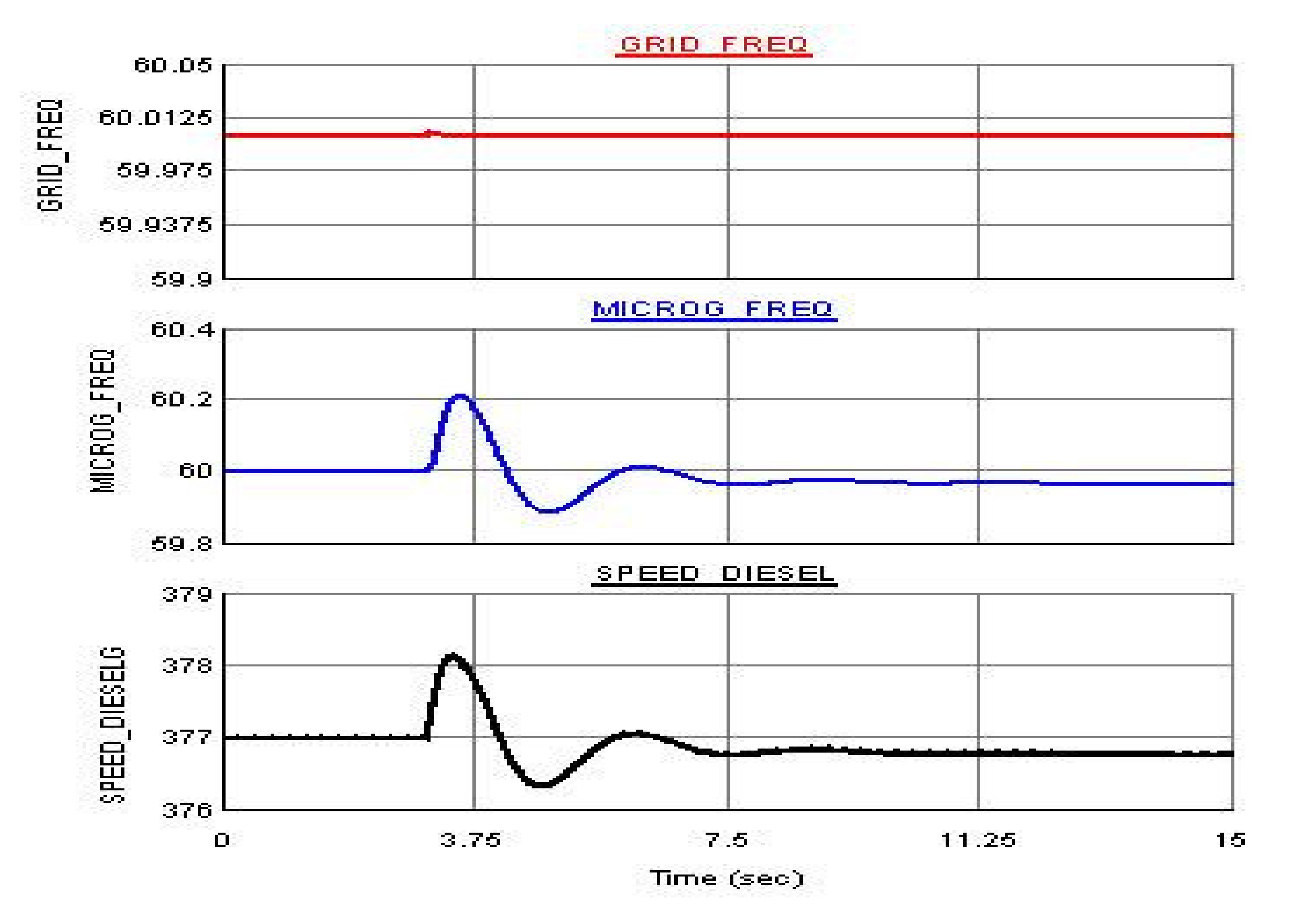
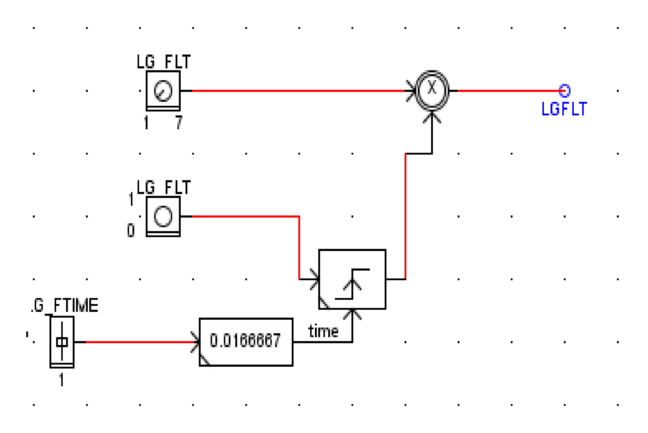
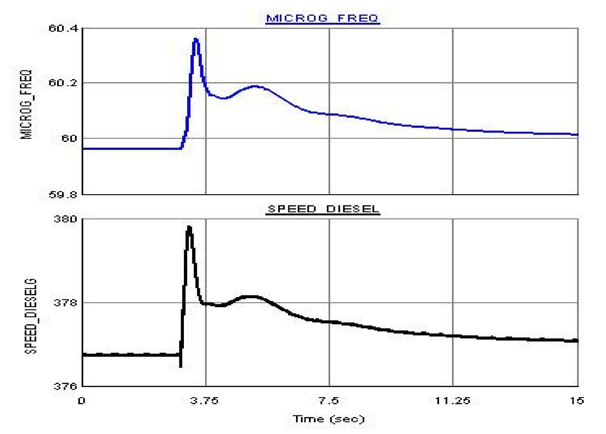
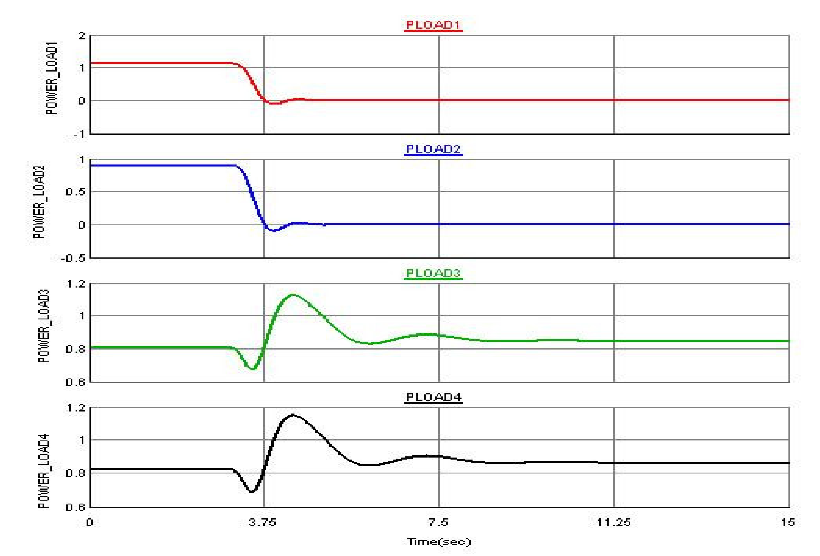
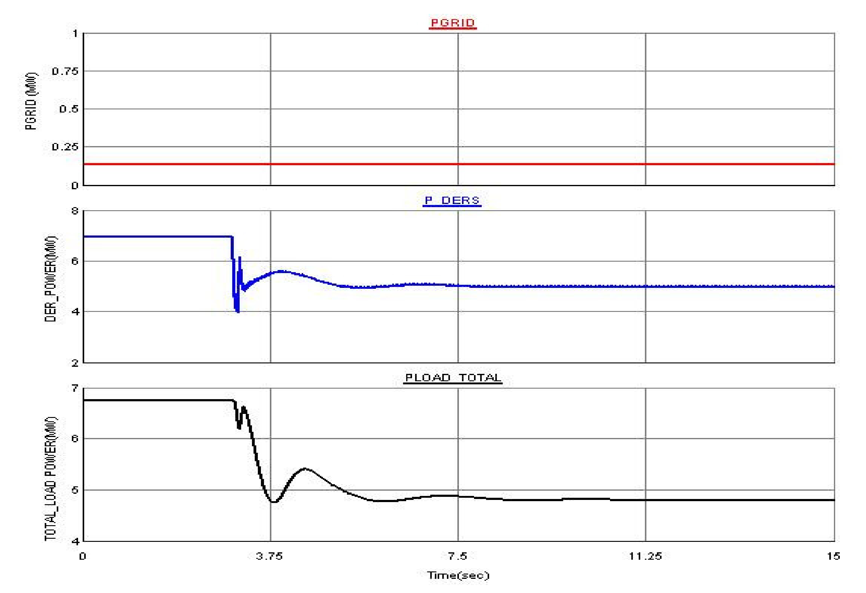
While in the island mode, a three-phase fault of six cycles (0.1 s) has been applied at Bus 6, with a fault logic shown in Figure 16. The system response is provided from Figure 17, Figure 18, Figure 19, Figure 20, Figure 21 and Figure 22. The frequency and speed of the diesel generator for the applied fault is presented in Figure 17. The frequency and rate of change of frequency now fall within the specified limit and time duration provided in Table 3, and an automatic load shedding is activated. The loads are shed in stages to restore the frequency, and consequently the stability of the microgrid network. To restore the frequency to the nominal value, loads 1 and 2 are shed automatically, as shown in Figure 18. Figure 19 presents the power generated from the DERs and the total power consumed by the loads. Once the two loads are removed, the power generated from the DERs is sufficient to supply the loads. The individual powers generated from the PV array, the wind and the diesel generator are depicted in Figure 20. Similar to the previous scenarios, the PV and the DFIG generated their corresponding powers with the proposed constant P–Q control. Figure 21 depicts the power consumed by the critical loads connected at Bus 5–7. The microgrid was able to ride through the fault with the reactive power support from the diesel generator, and the corresponding voltage for the applied fault is provided in Figure 22. Once the frequency is restored to the rated value, the disconnected loads can be connected back using a switch.

5. Conclusions

An efficient advanced automatic load shedding and power management control scheme of a microgrid based on PV, DFIG based wind, diesel generator and local loads is presented in this paper. The CIGRE medium voltage benchmark test system is used to demonstrate the controller’s capability. The microgrid voltage and frequency is maintained at the rated values by the grid during grid connected mode and in the island mode by the diesel generator in isochronous operation. In the island mode, the diesel generator provides reactive power to regulate the voltage, and maintains a constant speed irrespective of the load to regulate the microgrid frequency. In the island mode, whenever the power generated from the DERs is insufficient to support the loads, the load shedding control is activated to restore the frequency by removing the non-critical loads. The results show that the proposed control scheme manages the microgrid in both grid connected and island modes and improves the system stability and reliability. The advantage of the proposed approach is that the microgrid is fully controlled in grid connected, island and during fault events. The proposed load shedding approach does not need a dedicated communication channel that makes it economical for practical implementation. The cons of the proposed approach are that the critical and non-critical loads have to be assigned at the design stage of load shedding.

Author Contributions

M.Y.W. and M.A.A. initiated the idea and designed the controller. M.A.H. and the other authors perform the simulation and discussion. All authors have read and agreed to the published version of the manuscript.

Funding

The authors acknowledge the support provided by the Center for Engineering Research (CER), Research Institute at King Fahd University of Petroleum and Minerals (KFUPM). M. Abido would like also to acknowledge KFUPM support through funded project # RG171002.

Conflicts of Interest

The authors declare no conflict of interest.

References

  1. Parhizi, S.; Lotfi, H.; Khodaei, A.; Bahramirad, S. State of the Art in Research on Microgrids: A Review. IEEE Access 2015, 3, 1. [Google Scholar] [CrossRef]
  2. Planas, E.; Andreu, J.; Gárate, J.I.; De Alegría, I.M.; Ibarra, E. AC and DC technology in microgrids: A review. Renew. Sustain. Energy Rev. 2015, 43, 726–749. [Google Scholar] [CrossRef]
  3. Sahoo, S.K.; Kishore, N.K.; Sinha, A.K. Control Techniques in AC, DC, and Hybrid AC–DC Microgrid: A Review. IEEE J. Emerg. Sel. Top. Power Electron. 2017, 6, 738–759. [Google Scholar] [CrossRef]
  4. Radwan, A.A.A.; Mohamed, Y.A.-R.I. Networked Control and Power Management of AC/DC Hybrid Microgrids. IEEE Syst. J. 2014, 11, 1662–1673. [Google Scholar] [CrossRef]
  5. Che, L.; Shahidehpour, M.; AlAbdulwahab, A.; Al-Turki, Y. Hierarchical Coordination of a Community Microgrid with AC and DC Microgrids. IEEE Trans. Smart Grid 2015, 6, 3042–3051. [Google Scholar] [CrossRef]
  6. Xia, Y.; Wei, W.; Yu, M.; Wang, X.; Peng, Y. Power Management for a Hybrid AC/DC Microgrid with Multiple Sub-grids. IEEE Trans. Power Electron. 2018, 33, 3520–3533. [Google Scholar] [CrossRef]
  7. Institute of Electrical and Electronics Engineers (IEEE). IEEE Guide for Design, Operation, and Integration of Distributed Resource Island Systems with Electric Power Systems. In IEEE STD 1547.4-2011; Institute of Electrical and Electronics Engineers (IEEE): Piscataway, NJ, USA, 2011. [Google Scholar]
  8. Kaur, A.; Kaushal, J.; Basak, P. A review on microgrid central controller. Renew. Sustain. Energy Rev. 2016, 55, 338–345. [Google Scholar] [CrossRef]
  9. Bajwa, A.A.; Mokhlis, H.; Mekhilef, S.; Mubin, M. Enhancing power system resilience leveraging microgrids: A review. J. Renew. Sustain. Energy 2019, 11, 035503. [Google Scholar] [CrossRef]
  10. Zhuo, W.; Savkin, A.V.; Meng, K. Decentralized Optimal Control of a Microgrid with Solar PV, BESS and Thermostatically Controlled Loads. Energies 2019, 12, 2111. [Google Scholar] [CrossRef] [Green Version]
  11. Schütz, T.; Hu, X.; Fuchs, M.; Muller, D. Optimal design of decentralized energy conversion systems for smart microgrids using decomposition methods. Energy 2018, 156, 250–263. [Google Scholar]
  12. Worku, M.Y.; Hassan, M.A.M.; Abido, M.A. Real Time Energy Management and Control of Renewable Energy based Microgrid in Grid Connected and Island Modes. Energies 2019, 12, 276. [Google Scholar] [CrossRef] [Green Version]
  13. Zheng, Y.; Li, S.; Tan, R. Distributed Model Predictive Control for On-Connected Microgrid Power Management. IEEE Trans. Control Syst. Technol. 2018, 26, 1028–1039. [Google Scholar] [CrossRef]
  14. Peyghami-Akhuleh, S.; Mokhtari, H.; Blaabjerg, F. Autonomous Power Management in LVDC Microgrids Based on a Superimposed Frequency Droop. IEEE Trans. Power Electron. 2017, 33, 5341–5350. [Google Scholar] [CrossRef]
  15. Hassan, M.A.M.; Worku, M.Y.; Abido, M.A. Optimal Design and Real Time Implementation of Autonomous Microgrid Including Active Load. Energies 2018, 11, 1109. [Google Scholar] [CrossRef] [Green Version]
  16. Lidula, A.N.W.; Rajapakse, A. Microgrids research: A review of experimental microgrids and test systems. Renew. Sustain. Energy Rev. 2011, 15, 186–202. [Google Scholar] [CrossRef]
  17. Mohammadi, J.; Ajaei, F.B. Adaptive Voltage-Based Load Shedding Scheme for the DC Microgrid. IEEE Access 2019, 7, 106002–106010. [Google Scholar] [CrossRef]
  18. Mahat, P.; Chen, Z.; Bak-Jensen, B. Under frequency load shedding for an islanded distribution system with distributed generators. IEEE Trans. Power Del. 2010, 25, 911–918. [Google Scholar] [CrossRef]
  19. Reddy, S.S. Multi-objective based congestion management using generation rescheduling and load shedding. IEEE Trans. Power Syst. 2017, 32, 852–863. [Google Scholar]
  20. Shekari, T.; Aminifar, F.; Sanaye-Pasand, M. An Analytical Adaptive Load Shedding Scheme Against Severe Combinational Disturbances. IEEE Trans. Power Syst. 2015, 31, 4135–4143. [Google Scholar] [CrossRef]
  21. Tang, L.; McCalley, J. Two-Stage Load Control for Severe Under-Frequency Conditions. IEEE Trans. Power Syst. 2015, 31, 1943–1953. [Google Scholar] [CrossRef]
  22. Wu, J.; Wei, Z.; Li, W.; Wang, Y.; Li, Y.; Sauer, D. Battery Thermal- and Health-Constrained Energy Management for Hybrid Electric Bus based on Soft Actor-Critic DRL Algorithm. IEEE Trans. Ind. Inform. 2020. [Google Scholar] [CrossRef]
  23. Wei, Z.; Zhao, D.; He, H.; Cao, W.; Dong, G. A noise-tolerant model parameterization method for lithium-ion battery management system. Appl. Energy 2020, 268, 114932. [Google Scholar] [CrossRef]
  24. Reddy, S.S.; Sandeep, V.; Jung, C.-M. Review of stochastic optimization methods for smart grid. Front. Energy 2017, 11, 197–209. [Google Scholar] [CrossRef]
  25. Reddy, S.S. Optimal power flow with renewable energy resources including storage. Electr. Eng. 2017, 99, 685–695. [Google Scholar] [CrossRef]
  26. Zhou, Q.; Li, Z.; Wu, Q.; Shahidehpour, M. Two-Stage Load Shedding for Secondary Control in Hierarchical Operation of Islanded Microgrids. IEEE Trans. Smart Grid 2018, 10, 3103–3111. [Google Scholar] [CrossRef] [Green Version]
  27. Karimi, M.; Wall, P.; Mokhlis, H.; Terzija, V. A New Centralized Adaptive Underfrequency Load Shedding Controller for Microgrids Based on a Distribution State Estimator. IEEE Trans. Power Deliv. 2017, 32, 370–380. [Google Scholar]
  28. Rahmani, S.; Rezaei-Zare, A.; Rezaei-Zare, M.; Hooshyar, A. Voltage and Frequency Recovery in an Islanded Inverter-Based Microgrid Considering Load Type and Power Factor. IEEE Trans. Smart Grid 2019, 10, 6237–6247. [Google Scholar] [CrossRef]
  29. De Nascimento, B.N.; de Souza, A.C.Z.; de Carvalho Costa, J.G.; Castilla, M. Load shedding scheme with under-frequency and under voltage corrective actions to supply high priority loads in islanded microgrids. IET Renew. Power Gener. 2019, 13, 1981–1989. [Google Scholar] [CrossRef] [Green Version]
  30. Nourollah, S.; Gharehpetian, G.B. Coordinated Load Shedding Strategy to Restore Voltage and Frequency of Microgrid to Secure Region. IEEE Trans. Smart Grid 2019, 10, 4360–4368. [Google Scholar] [CrossRef]
  31. CIGRE C6.04.02 Task Force, Benchmark Modeling and Simulation for Analysis, Design, and Validation of Distributed Energy Systems. September 2006. Available online: https://www.yumpu.com/en/document/read/4578628/cigre-task-force-c60402-developing-benchmark-models-for- (accessed on 31 January 2019).
  32. Worku, M.Y. Power Smoothing Control of PMSG Based Wind Generation Using Supercapacitor Energy Storage System. Int. J. Emerg. Electr. Power Syst. 2017, 18. [Google Scholar] [CrossRef]
  33. Worku, M.Y.; Abido, M.A. Maximum Power Control of DFIG Based Grid Connected Wind Turbine Generator System. In Proceedings of the International Conference on Renewable Energies and Power Quality (ICREPQ’18), Salamanca, Spain, 21–23 March 2018. [Google Scholar]
  34. Gao, H.; Xu, Y.; Liu, C.-C.; Chen, Y. Dynamic load shedding for an islanded microgrid with limited generation resources. IET Gener. Transm. Distrib. 2016, 10, 2953–2961. [Google Scholar] [CrossRef]
  35. Zin, A.A.M.; Hafiz, H.M.; Wong, W. Static and dynamic under-frequency load shedding: A comparison. In Proceedings of the International Conference on Power System Technology, Singapore, 21–24 November 2004; Volume 1, pp. 941–945. [Google Scholar]
Figure 1. The distributed energy resources (DER)-based microgrid system.
Electronics 09 01487 g001
Figure 2. Diesel Generator, exciter and speed governor.
Electronics 09 01487 g002
Figure 3. Diesel generator speed governor controller.
Electronics 09 01487 g003
Figure 4. Doubly fed induction generator (DFIG)-based wind turbine system.
Electronics 09 01487 g004
Figure 5. DFIG maximum power point tracking (MPPT) control.
Electronics 09 01487 g005
Figure 6. Grid side converter (GSC) decoupled controller.
Electronics 09 01487 g006
Figure 7. Rotor side converter (RSC) controller.
Electronics 09 01487 g007
Figure 8. Load shedding logic implemented in real time digital simulator (RTDS).
Electronics 09 01487 g008
Figure 9. Microgrid system frequency before and after islanding.
Electronics 09 01487 g009
Figure 10. Grid, DERs and Load active powers from grid connected to island mode.
Electronics 09 01487 g010
Figure 11. Photovoltaic (PV), wind and diesel generator generated powers.
Electronics 09 01487 g011
Figure 12. Grid, DERs and Load reactive powers.
Electronics 09 01487 g012
Figure 13. Non-critical load active powers (Loads at Buses 1–4).
Electronics 09 01487 g013
Figure 14. Critical load active powers (Loads at Buses 5–7).
Electronics 09 01487 g014
Figure 15. Microgrid voltage at the point of common coupling (PCC).
Electronics 09 01487 g015
Figure 16. Fault scenario implemented in real time digital simulator (RTDS).
Electronics 09 01487 g016
Figure 17. Microgrid frequency and speed of the diesel generator.
Electronics 09 01487 g017
Figure 18. Non-critical loads 1 and 2 are shedded.
Electronics 09 01487 g018
Figure 19. Grid, DERs and Load active powers.
Electronics 09 01487 g019
Figure 20. The generated active powers from PV, wind and diesel generator.
Electronics 09 01487 g020
Figure 21. Non-shed able Critical load active powers (Loads at Buses 5–7).
Electronics 09 01487 g021
Figure 22. Microgrid voltage for the applied three phase fault.
Electronics 09 01487 g022
Table 1. Non-Critical Load Data.
BusMVApfP (MW)Q (Mvar)
1 (Load 1)1.5180.91.370.66
2 (Load 2)1.10.951.0450.343
3 (Load 3)1.0320.90.930.45
4 (Load 4)1.0680.90.960.47
Table 2. Critical Load Data.
BusPhase A (KVA)Phase B (KVA)Phase C (KVA)pf
5 (Load 5)3256251000.95
6 (Load 6)1257253000.95
7 (Load 7)2756251500.95
Table 3. Under Frequency Criteria for Load Shedding.
Stages (Priority) CriteriaTime(s)Load
1 f 59.5 Hz o r d f d t 1.5 Hz sec 0.1Load 1
2 f 58.7 Hz o r d f d t 1.5 Hz sec 0.08Load 2
3 f 58.3 Hz 0.08Load 3
4 f 58 Hz 0.08Load 4