Article

A Bi-Level Path Planning Algorithm for Multi-AGV Routing Problem

School of Mechanical Engineering, Dalian University of Technology, Dalian 116024, China
*
Author to whom correspondence should be addressed.
Electronics 2020, 9(9), 1351; https://doi.org/10.3390/electronics9091351
Submission received: 10 July 2020 / Revised: 15 August 2020 / Accepted: 17 August 2020 / Published: 20 August 2020
(This article belongs to the Section Systems & Control Engineering)

Abstract

:
Avoiding the multi-automated guided vehicle (AGV) path conflicts is of importance for the efficiency of the AGV system, and we propose a bi-level path planning algorithm to optimize the routing of multi-AGVs. In the first level, we propose an improved A* algorithm to plan the AGV global path in the global topology map, which aims to make the path shortest and reduce the AGV path conflicts as much as possible. In the second level, we present the dynamic rapidly-exploring random trees (RRT) algorithm with kinematic constraints to obtain the passable local path with collisions in the local grid map. Compared to the Dijkstra algorithm and classic A* algorithm, the simulation results showed that the proposed bi-level path planning algorithm performed well in terms of the search efficiency, significantly reducing the incidence of multiple AGV path conflicts.

1. Introduction

In recent years, with the development of industrial intelligence, unmanned storage, intelligent logistics, and intelligent factories have been gradually implemented and have become a reality [1,2]. The automated guided vehicle (AGV) plays a vital role in significantly reducing transportation costs and improving transportation efficiency [3,4]. Recent papers focused on planning the paths of AGVs to complete transportation tasks more efficiently in the factory without collision, deadlock, and other traffic problems [5,6].
For the problem of AGV path planning, researchers have adopted different methods. There are three types of AGV path planning algorithms as far as we know, one of which is the classic graph search algorithm [7,8,9]. Kim and Jin [8] applied Dijkstra’s shortest-path algorithm to plan AGVs path through the concept of a time-windows graph. Chunbao Wang et al. [9] presented a multi-AGV A* algorithm based on a collision-free dynamic path planning method. The algorithm classified the potential conflicts to search the shortest path with conflict-free effectively.
Sampling-based methods are also available. Alex, C et al. [10] used a method based on Voronoi graph to solve AGV path planning. Zhe, L et al. [11] improved RRT (rapidly-exploring random trees) method with arc approximation collision detection, which aims to finish local path planning fast enough to satisfy real-time tasks.
Additionally, some intelligent algorithms are often used for this problem. Chengwei He et al. [12] proposed a method to improve the heuristic function in the ant colony algorithm to deal with the optimal path for AGV in the turn of the complex factory environment, which aims to avoid obstacles, and ensure safety and save transportation time. Besides, neural networks [13,14], simulated annealing [15], tabu search [16], and the genetic algorithm [17,18,19] have emerged. After using the above algorithm for single AGV path planning, some rules or other algorithms are usually used to solve the problem of multiple AGV conflicts or deadlocks. However, most of the algorithms performing path planning are based on artificially abstracted topological maps, which is still far from the real map in the actual production environment. Combined with the real factory environment, it can effectively resolve the conflicts of multiple AGVs and plan the path better.
With the significant progress of AGV technology, the new AGVs have the capability of simultaneous localization and mapping (SLAM) [20,21,22]. The AGVs with SLAM establish the occupied grid map through its sensor information and can carry out path planning through the built map [23]. However, when AGVs build a map in a larger factory, the cumulative error will be increasingly affected by the shortcomings of Kalman filtering, and the grid map will occupy a larger storage space and generate a lot of calculation volume. Moreover, there is a lack of macro scheduling and planning among multiple AGVs. Therefore, it is unrealistic for the AGV to use only the local map built by the AGV with SLAM for path planning in a large factory, and the supplement of the global map will make up for this.
In this study, we propose a bi-level path planning algorithm. In the global topology map, we employ the improved A* algorithm to plan the path of each AGV for obtaining an optimal path in the topology map. Additionally, then, we employ the dynamic RRT algorithm with kinematic constraints to obtain the passable local path in the local grid map.
The purpose of this paper is to minimize the time for the AGV to complete the task by resolving the AGV’s path conflicts while maintaining the AGV’s shortest path. Our main contributions in this paper are as follows:
  • We propose a bi-level path planning algorithm. The second level algorithm reduces and resolves conflicts by using a grid map that reflects the real environment structure of the factory while maintaining the shortest AGV path planned by the first level algorithm.
  • We consider that the AGVs with low priority use RRT with kinematics constraints to travel along a temporary path in the grid to give way to the AGVs with high priority when AGV paths of different priorities conflict.
  • We consider that the AGVs encounter dynamic obstacles during the execution of the task and adopt a strategy to solve it.
The rest of this paper is organized as follows. The description of the environment and the problem model are in Section 2. We propose a bi-level path planning algorithm for this problem in Section 3. In Section 4, we present our simulation result and analyze it. Finally, we conclude this paper in Section 5.

2. Manufacturing Environment and AGVs Routing Modeling

2.1. Environment Modeling

The map environment is the basis of AGV path planning. The AGV used in this paper is fusion navigation of laser and odometer, which has a high degree of freedom and does not require laying magnetic strips or two-dimensional codes in the factory for guidance. However, in the first level path planning algorithm, we still abstracted the overall environment map as a topological map, and perform path planning for the AGV on a global scale. In the second level path planning algorithm, the local grid map established by AGV was used.

2.1.1. Topological Modeling

The topological map of the factory environment in this study was modeled with points and lines with the bidirectional lanes. Additionally, the abstracted map was modeled as an undirected graph. According to the real environment of the manufacturing plant, we must first define the attributes of each point, such as location, types of point (storage point, worksite point, charging point, etc.), and determine the line according to the traffic situation. Driving along the line, the AGV will hardly encounter obstacles, but the AGV will encounter unexpected obstacles in the grid composed of lines. According to the drawing of the factory, the topological map shown in Figure 1 was abstracted. This map was employed in the upper computer layer, with the operation area on the left and the storage area on the right in the figure.

2.1.2. Grid Modeling

Through its own SLAM function, AGVs can build a grid map in the local environment in real-time, as shown in Figure 2. In the figure, a small white square area is a passable area, and a small black square is an impassable area. This map is used in the AGV layer of the lower computer. The use of occupied grid maps in local environments effectively avoids the problems of large space occupied by grid maps and complicated search calculations.

2.2. Multi-AGVs Path Planning Modeling

The goal of multi-AGV path planning is to make the total time for all AGVs to complete the task the shortest. The time spent in the process of AGV transportation is divided into time for loading or unloading, time for walking, and time for resolving path conflicts, respectively set to Tpd, TR, and TC. Let k denote the number of tasks. So, the sum of the time costs is shown in Equation (1):
T C o s t = n = 1 k ( T p d + T R + T C )
Take out the storage area separately. In the topology map shown, let G = ( V , E ) denote the entire undirected connection network, where V represents the set of nodes V = {v1, v2, v3,…, vn}, and E represents the set of edges E = {e1, e2, e3,…, en}, and each edge can be represented by a pair of adjacent nodes, which is shown in Equation (2):
e n = { ( v p , v q ) : v p , v q ϵ V }
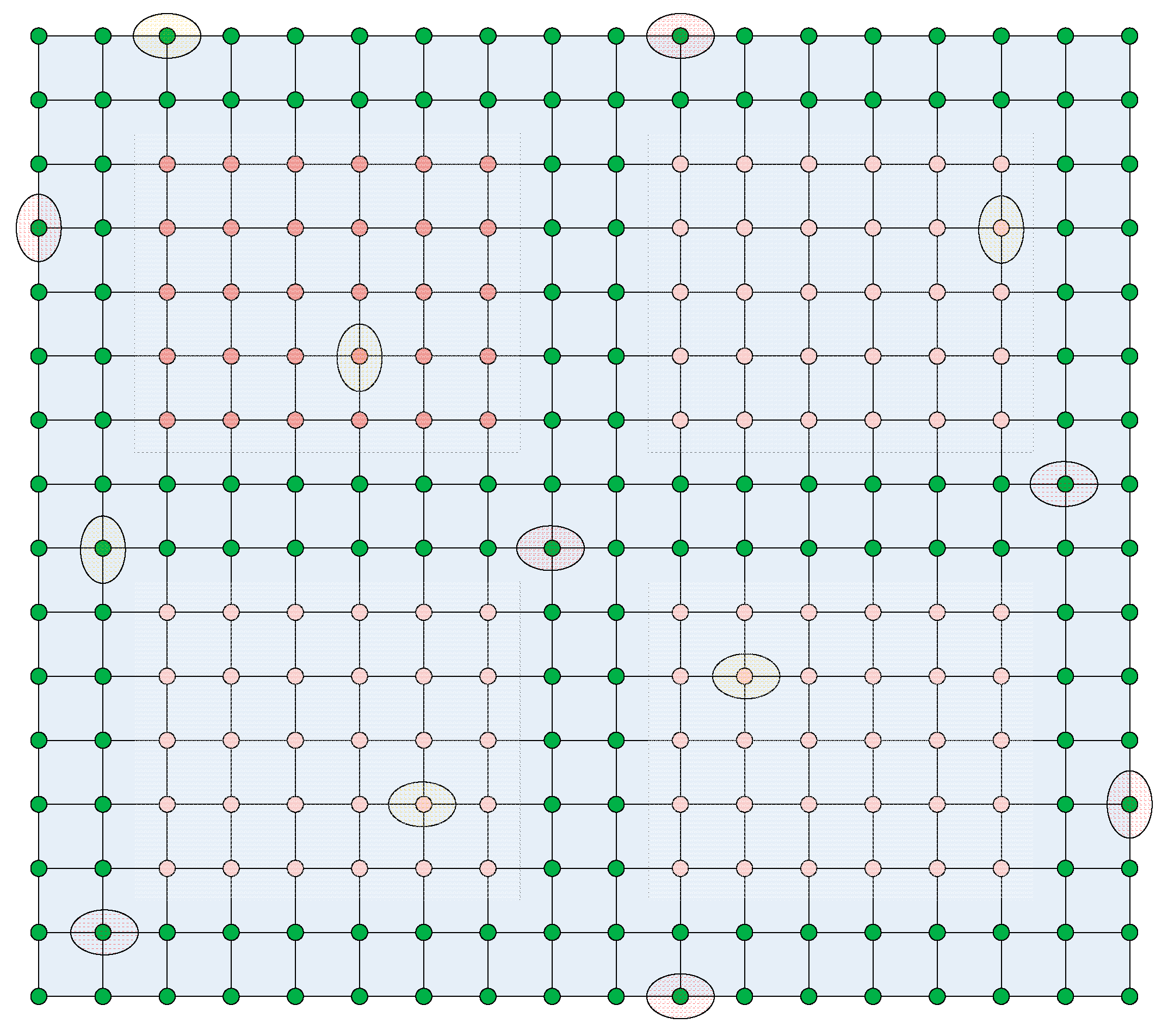
The topological map of the storage area is shown in Figure 3. The circle node is a road node, where the green node represents the node on a normal road, and the red node indicates that the node is under a shelf. The red ellipse denotes the AGV carrying the shelf or goods, and the yellow ellipse indicates the AGV that is empty. There are two states of AGV in the manufacturing plant, one is the AGV carrying shelves or goods, and the other is the AGV without the load. The AGV in this study is composed of a chassis and a lifting device. The no-load AGV can travel under the shelf. So, in this paper, we could make the following assumptions:
  • No-load AGVs can pass through any node (green and red);
  • AGVs carrying shelves or goods can only pass through green nodes;
  • The line between the nodes is a one-way lane but can be driven in both directions;
  • The safety radius of AGV is 0.2 m;
  • The AGV has three states: no-load stationary, load driving, and no-load driving.

3. The Bi-Level Path Planning Algorithm

The AGV path planning in this paper involves both the upper computer layer and the AGV layer. Among them, the path planning of the upper management layer was carried out in the traditional topological map. The manufacturing factory was manually modeled to abstract the topological map. In the topology map composed of points and lines, a global path planning was performed on the AGV to obtain the area that the AGV travels through. However, the maps abstracted as points and lines were somewhat different from the actual maps. However, we could use the AGV mapping function to obtain a grid map of some areas. The grid map had more accurate scale information and had a high degree of fit with the actual map. Therefore, in areas where the AGV conflicts occur, we could call the grid map, restore the real map information, and dynamically adjust the path within a small range, to solve the AGV conflict deadlock.

3.1. First-Level Path Planning Algorithm Based on the Topological Map

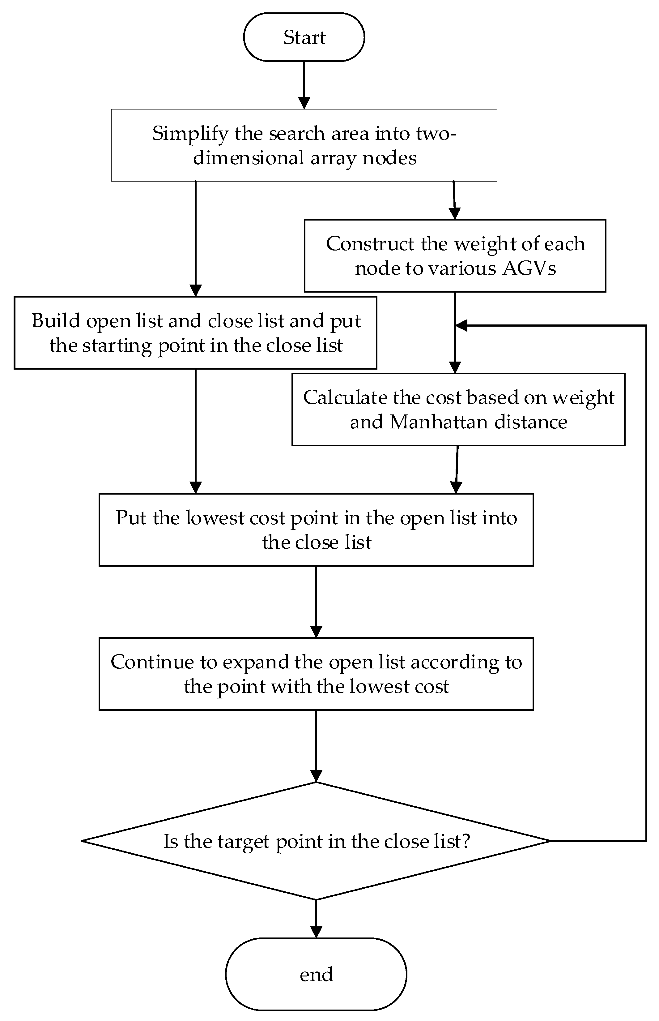
In the static global factory map, the classic A* algorithm can find the shortest path for a single AGV effectively [24]. It is flexible to be improved to solve our problems. In our study, multiple AGVs in the factory were performing tasks simultaneously. According to the characteristics of the manufacturing plant storage area in the research, we improved the classic A* algorithm to solve the problem. Specifically, when planning a single AGV path, we considered reducing the possibility of AGV traffic conflicts. The specific steps of the improved A* algorithm are as follows:
(1)
Establish the weight matrix of corresponding nodes of AGV in different states. For AGVs carrying shelves or goods, the weight of a circular node is 1 + 0.1 × 1 = 1.1, and the node of a triangle is infinity. For no-load AGVs, the weight of the circular node is 1 + 0.1 × 1 = 1.1, and the weight of the triangular node is 1.
(2)
Build an extensive list and close list. The points to be detected in the path planning are stored in the open list, and the points that have been detected are stored in the close list. Each node in the list has three attributes: parent node, G, and H, where the parent node is the previous node. G is the cost from the starting node to the current node, and H is the cost from the current node to the target node. Initially, the close list contains only the starting node vi.
(3)
According to the heuristic function F(x) = G + H, calculate the node cost to search for the optimal path of the car in different states. G is the product of the G value of the node’s parent node plus the distance from the node’s parent node to its Manhattan and the node’s weight for this state of AGV. H is the Manhattan distance from the current node to the target node.
(4)
Search the adjacent node of the last node in the close list. If the adjacent node is already in the close list, the point is ignored; if its adjacent node is in the open list, then compare the F value through this point with the F value of the previous node, if current F is larger, ignore it, otherwise update the attribute of the adjacent node, update its parent node to this node and update the G value to a smaller G value; if its adjacent node is not in the open list, then calculate its G and H and add it to the open list.
(5)
Put the node with the smallest F value in the currently open list into the close list, and determine whether the target node is in the close list at this time. If the target node is in the close list at this time, the optimal path of the car in this state is found, otherwise, skip to step 4.
The flow chart of the algorithm is shown in Figure 4.

3.2. Second-Level Path Planning Algorithm Based on the Grid Map

3.2.1. Kinematic Constraints of AGV

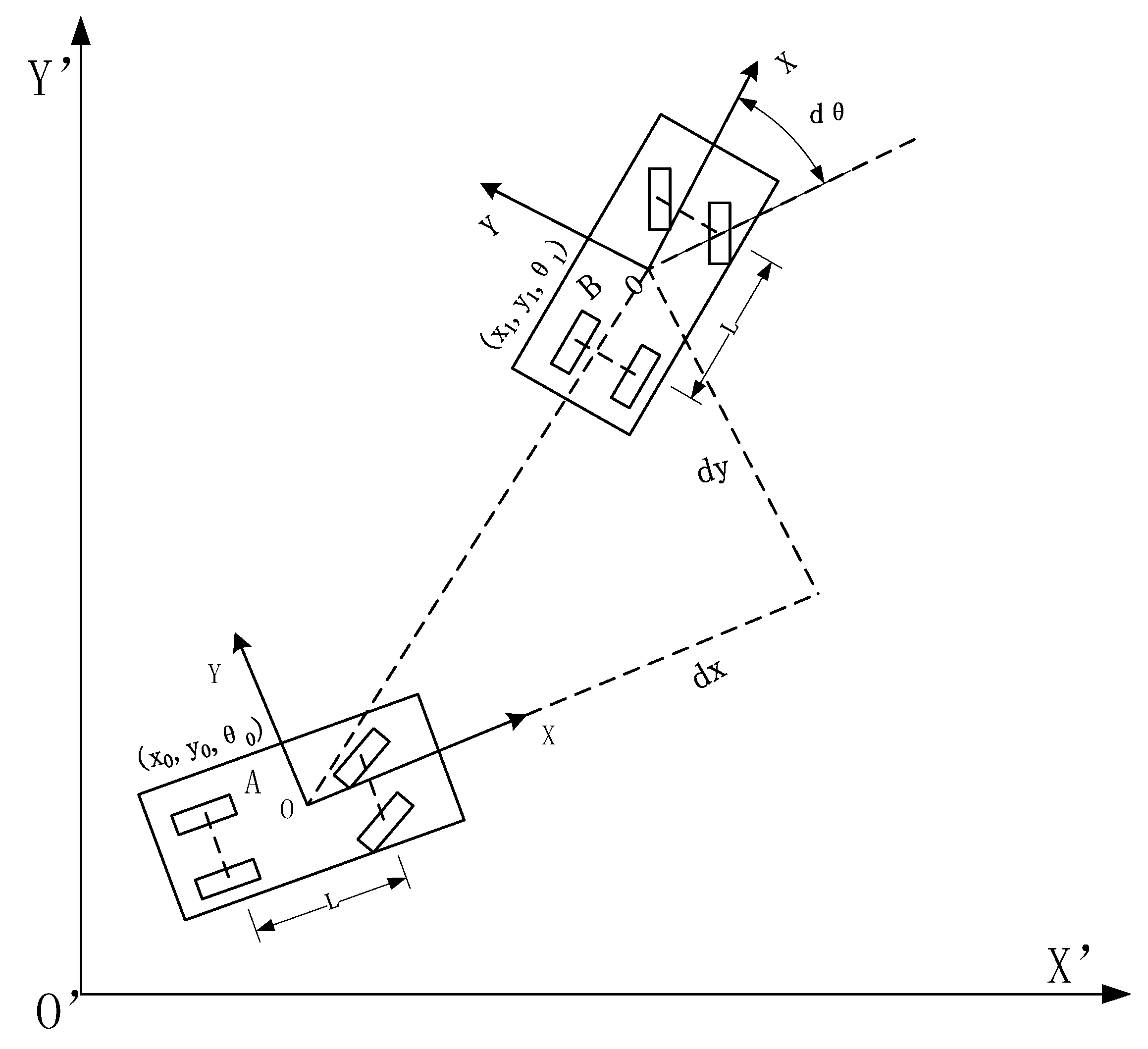
The AGV in the real environment is constrained by kinematics, and its configuration space is composed of two-dimensional coordinates and orientation. We built a kinematics model in a discrete state space, as shown in Figure 5. The position and posture of the AGV can be represented by ( x , y , θ ) , and the control quantity of the AGV can be represented by ( v x , v y , ω z ) .
During the time Δ t , the AGV moves from point A ( x 0 , y 0 , θ 0 ) to point B ( x 1 , y 1 , θ 1 ) at speed ( v x , v y , ω z ) . In the vehicle coordinate system, the AGV moved ( d x , d y , d θ ) in three degrees of freedom. As Equation (3):
{ d x = v x Δ t d y = v y Δ t d θ = ω z Δ ψ
The coordinate of the AGV of point B in coordinate system A is ( d x , d y , d θ ) , and then the conversion matrix from coordinate system B to coordinate system A is Equation (4).
B A T = [ cos ( d θ ) sin ( d θ ) d x sin ( d θ ) cos ( d θ ) d y 0 0 1 ]
It is known that the coordinate position of the coordinate system A in the geodetic coordinate system O’ is ( x 0 , y 0 , θ 0 ) , and then the conversion matrix of the coordinate system A to the geodetic coordinate system O’ is Equation (5).
T A O = [ cos θ 0 sin θ 0 x 0 sin θ 0 cos θ 0 y 0 0 0 1 ]
Then the conversion matrix of coordinate system B in coordinate system O′ is Equation (6).
T B O = A O T B A T
The coordinate position of coordinate system B in coordinate system O′ is Equation (7).
( x 1 , y 1 , θ 1 ) = ( T B O ( 0 , 2 ) , T B O ( 1 , 2 ) , atan 2 ( T B O ( 1 , 0 ) , T B O ( 0 , 0 ) ) = ( d x cos θ 0 d y sin θ 0 , d x sin θ 0 + d y cos θ 0 , θ 0 + d θ )
According to the coordinate transformation theory in different coordinate systems, from Equation (7), the matrix of the AGV discrete-time kinematics model is expressed as Equation (8).
[ x 1 y 1 θ 1 ] = [ x 0 y 0 θ 0 ] + [ cos θ 0 sin θ 0 0 sin θ 0 cos θ 0 0 0 0 1 ] [ v x v y ω z ] Δ t
According to kinematics analysis, the AGV has non-holonomic kinematic constraints. It cannot move in a direction perpendicular to its heading and has a maximum steering angle (or minimum steering radius). In the following, under the kinematic constraints of the AGV, the RRT algorithm was used to perform path planning at the AGV layer.

3.2.2. RRT Algorithm with Kinematic Constraints

The second level path planning algorithm is based on grid maps, with special consideration of AGV kinematic constraints. By imposing extra constraints on the motion of the AGV, the generation of new structures in the RRT algorithm was simplified and accelerated, and the AGV could quickly generate a trajectory during driving. Additionally, according to the characteristics that grid maps are closer to the real environment of the manufacturing factory, real-time dynamic path planning was carried out to break through the limitations of topological maps, and AGV could find a path for itself to avoid conflicts in a local scope.
The local conflicts that occur when multiple AGVs work together are generally divided into three types: catch-up conflicts, confrontation conflicts, and intersection conflicts. When the AGV is in operation, it is easy to encounter people, scattered goods or garbage, and other physics that should not appear, and the path will be obstructed by objects. The problems in the four kinds of multi-AGV operation are shown in Figure 6.
When carrying out the first-level path planning in the topology map, the above four problems are often encountered. However, these conflicts may not actually exist. In this paper, the AGVs were non-trajectory AGVs, and the AGVs did not have to follow the lines in the topological map. The topology map was only abstracted for AGV’s global path planning. When the above four problems occur in the topology map, the problem may be easily solved by calling the grid map of the AGV layer. Through the establishment of the grid map, AGV can break through the limitations of the topological map, and can find a path for itself to avoid conflicts in local areas.
The RRT algorithm is a fast search algorithm and widely used in local path planning for obstacle avoidance, which uses a random sampling planning method, does not require preprocessing, can directly consider the kinematic constraints, and has a fast search speed. This algorithm quickly searches the grid space of the whole local environment and finds a passable path, whose primary purpose is to access the unexpanded part of the grid space via rapid splitting. The algorithm structure is as follows (Algorithm 1):
Algorithm 1. Pseudocode for RRT Algorithm with Kinematic Constraints.
Input:
Configuration file of grid map built by AGV itself, Kinematic parameters of the AGV, Maximum search times K, Initialization parameters Xinit, and Search step size Δt
Output:
Search tree G containing the nodes of the passable path
1:G.init(Xinit)
2:For i=0 to K do
3:  Xrand random-config(Xfree)
4:  Extend(G, Xrand)
5:End for
6:Return G
Function: Extend(G,Xrand)
1:Xnear nearest-neighbor(G, Xrand)
2:Rrand random-config(Xnear)
3:If compare(Rrand) then
4:  u select-input(Xrand, Xnew)
5:  Xnew new-state(Xnear, u, Δt)
6:  If kinematics- satisfaction(Arcf) and collision-free-path(Xnear, Xnew) then
7:    G.add-node(Xnew)
8:    G.add-node(Xnear,Xnew,u)
9:  End if
10:End if
11:Return G
The specific implementation process is described below:
Step 1 
initialize the search tree G with X;
Step 2 
randomly select a configuration space Xrand from Xfree;
Step 3 
execute the Extend() function to add one of nodes representing a passable route to the search tree G. In the Extend() function:
(1)
Select the nearest node Xnear in G by the nearest-neighbor() function;
(2)
Generate a circle named Rrand, whose arc passes through the x and y coordinates in Xnear. By maintaining a certain angle, the AGV can go from Xnear to Rrand. If the radius of this Rrand circle is smaller than the smallest steering angle of the AGV, then return to step 2;
(3)
This circle Rrand is divided into two arcs, the arc from Xnear to Rrand is the trajectory of the AGV car named Arcf;
(4)
Find the movement from Xnear to Xnew in the direction of Xrand; Starting from Xnear, AGV drive along Arcf for a while, then AGV reaches a new point Xnew;
(5)
If the motion satisfies the kinematic constraint Equation (8) and there is no collision in this movement, Add Xnew to the tree G, and the edge goes from Xnear to Xnew;
(6)
If Xnew is in Xgoal, it ends successfully, if not, it skips to continue to execute the Extend() function.
In the RRT algorithm, a black square in Figure 2 acts as the obstacles and a node in the black square is impossible to be contained in the set of nodes representing a passable route. A white square has the opposite effect. Additionally, the passable path can be easily obtained by backtracking returned search tree G.
When the two AGVs conflict in the topology map, the AGV with higher priority can use the original path, while the AGV with lower priority will use the RRT algorithm to search for accessible areas in the local grid map.
Through the first level of path planning at the upper computer management control layer, we determined the node where the AGV performs the task. When the AGV encounters path conflicts or dynamic obstacles, the second layer of path planning was performed to ensure the efficient and accurate operation of the AGV system.

4. Experimental Studies

The specifications of the system and software used for simulation are: the upper computer uses OS-Windows 10 Enterprise 64-bit, NetBeans, Visual Studio 2017, and the lower computers use OS-Ubuntu 18.04, TCS version 4.14, ROS kinetic.

4.1. Experiments on Functionality of the Improved A* Algorithm

First, through a series of computer simulations, we observed the functionality of the improved A* algorithm in extreme cases.
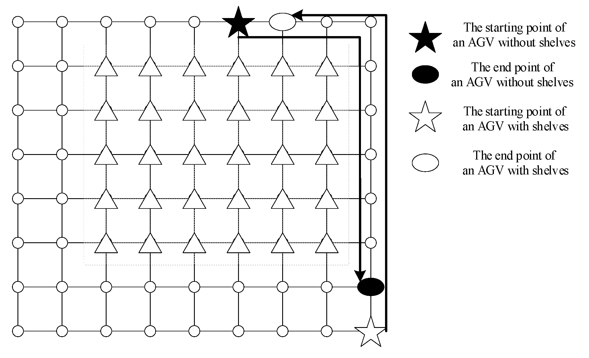
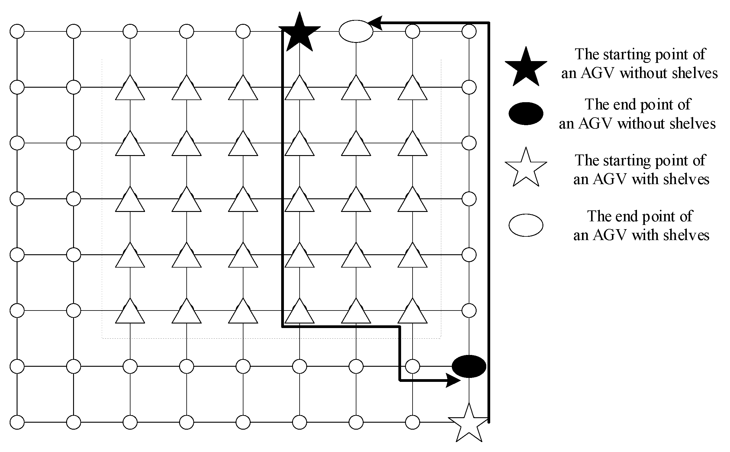
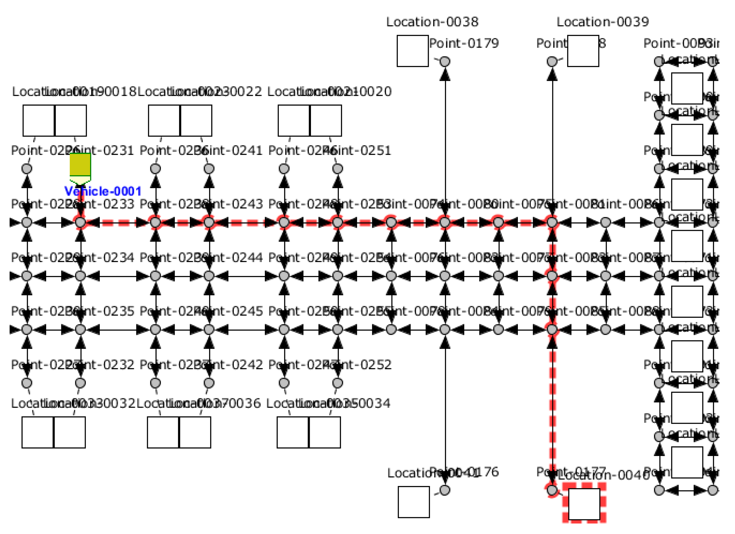
Path planning of AGV based on the classic A* algorithm and improved A* algorithm are shown in Figure 7 and Figure 8, respectively. It can be seen that the paths planned by the two algorithms for the loaded AGV were roughly the same. Due to the indistinguishable processing of triangular nodes and circular nodes, the classical A* algorithm had a high overlap in the path planning for the path of the no-load AGV and the AGV with shelves. It can be seen that the paths planned by the two algorithms for the loaded AGV were roughly the same. In Figure 7, if two AGVs performed tasks in the same interval, they would encounter conflict. At this time, it is necessary to use other algorithms to resolve the conflict. However, in Figure 8, even if the tasks were executed at the same time, the two AGVs would not encounter congestion, while ensuring that the path was also optimal. It shows that the improved A* algorithm could find better paths and reduce AGV conflicts.

4.2. Experiments on the Effectiveness of the Improved A* Algorithm

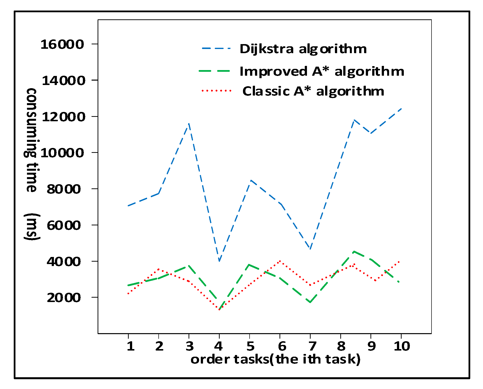
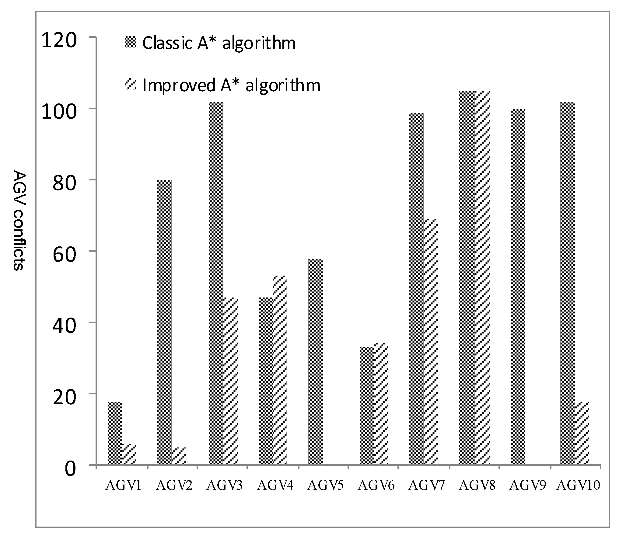
Then we studied the search efficiency and effectiveness of the improved A* algorithm. In the experiment, 10 orders were randomly generated. The results of Dijkstra, the classic A*, and improved A* are shown in Figure 9. It can be seen that the efficiency of the improved A* algorithm and the classic A* algorithm in path search was the same, which was about twice that of the Dijkstra algorithm. Next, we studied the effectiveness of the improved A* algorithm in reducing AGV conflicts further. In the topology map of the manufacturing plant, 50 orders were randomly generated, and 10 AGVs were executed. During the experiment, the AGV would not lock the currently occupied road section. Statistics of the number of AGV conflicts under the classic A* algorithm and the improved A* algorithm are shown in Figure 10. It can be observed that the conflicts of the improved A* algorithm were reduced by 54.7% compared to the classic A* algorithm.

4.3. Experiments on the Bi-Level Path Planning Algorithm

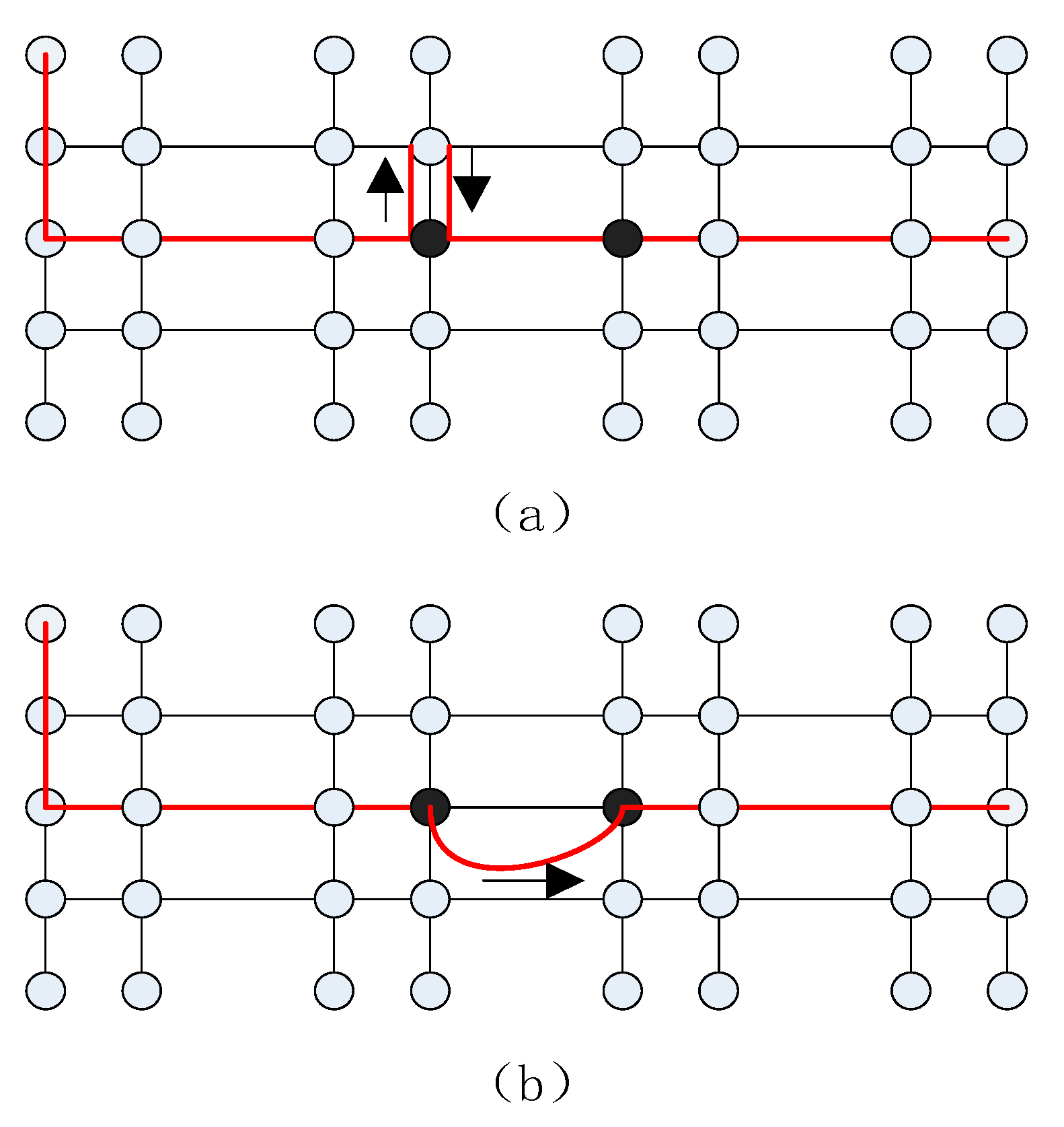
When the two AGVs collide, it has little effect on the AGV with higher priority, but the path of the AGV with lower priority may become very troublesome. As shown in Figure 11, the two AGVs encountered a collision at the two black nodes, and the left AGV had a lower priority. In Figure 11a, it shows the trajectory of the AGV to resolve conflicts and complete tasks based on traffic rules. Figure 11b shows the trajectory of AGV solving conflicts and completing tasks based on the bi-level path planning algorithm proposed in this paper. Since the bi-level path planning algorithm uses a grid map in its AGV layer and implements dynamic path planning in a local area, the planned AGV path was shorter. The algorithm based on traffic rules needs to pass other nodes to avoid the high priority AGV, which reduced the efficiency of AGV.
We studied the stability of the AGV system to control a single AGV, using an AGV and randomly generating ten orders. The specific process is as follows:
  • Through CloudTCS, input the target point and execute the action;
  • The system assigns the order task to this AGV;
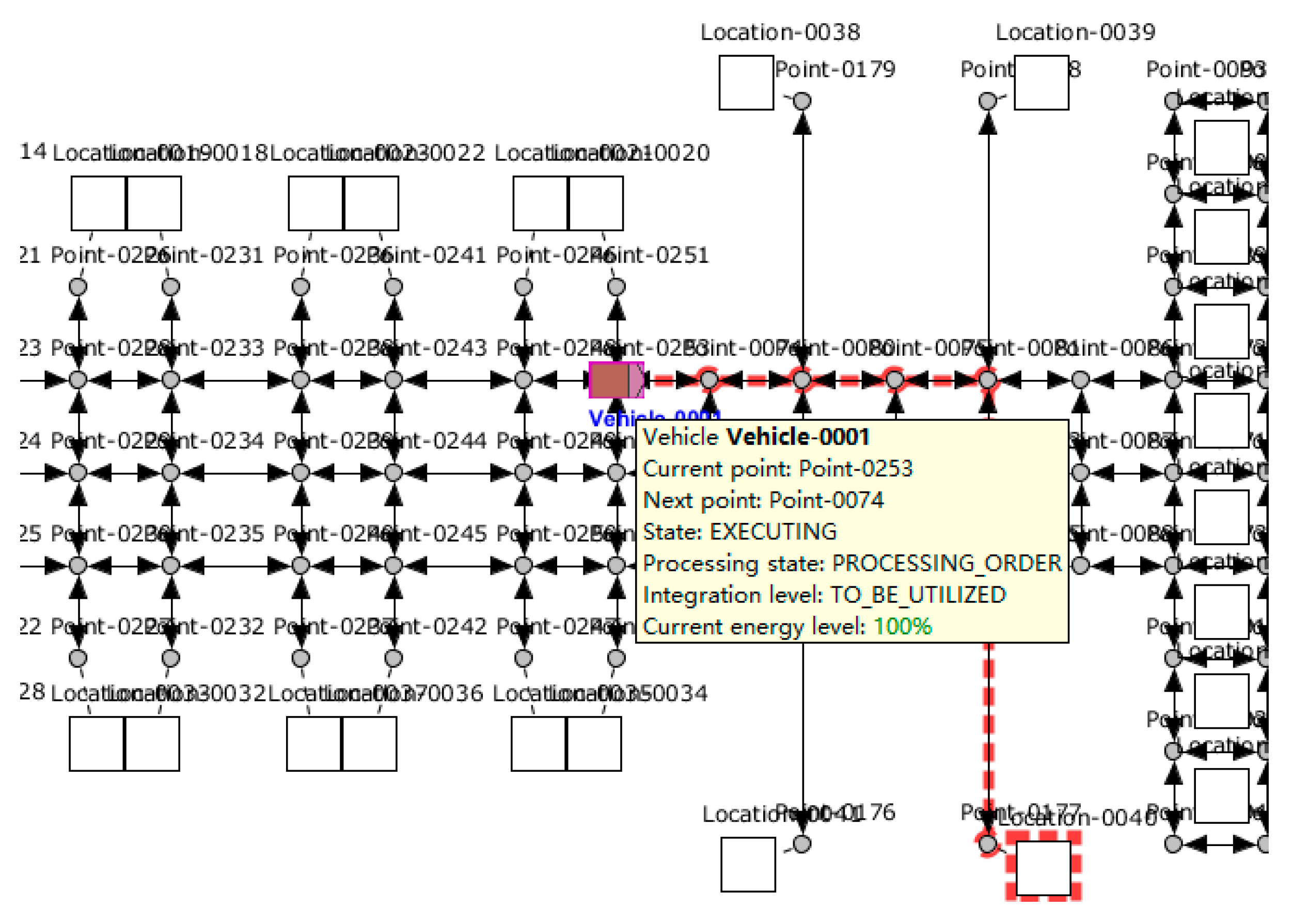
  • After the first-level path planning algorithm is planning a path for the AGV, as shown in Figure 12, the status of both the order and the AGV has changed. The AGV starts to execute the task, as shown in the blue circle in Figure 13, and the current state of the AGV can be observed in real-time.
  • After the AGV completes the task (Figure 14), the status changes to IDIE and waits for the next order.
In 10 experiments, the paths planned by the system for AGV were the shortest, and all tasks were successfully completed, as shown in Figure 14. The AGV system based on the bi-level path planning algorithm could perform actual AGV scheduling, and complete single AGV scheduling tasks efficiently and stably.
In the actual manufacturing factory, there were up to seven AGVs running at the same time because of the limitation of task volume. Next, we studied the efficiency of the bi-level path planning algorithm, randomly generating 100 orders and using seven AGVs. The specific process is as follows:
  • One hundred orders are generated and wait in the queue;
  • Establish connections with all AGVs (as shown in Figure 15). According to the priority strategy, the first seven orders are assigned to the AGV, then use the first-level path planning algorithm directly to plan the optimal path.
  • AGV accepts orders cyclically. When encountering conflicts, AGV can solve the conflicts well through the local grid map established by itself.
  • Seven AGVs completed 100 order tasks.
The proposed algorithm completed the task. The path of the AGV performing tasks is shown in Figure 16. It can be seen that the first level path planning algorithm planned the shortest path for each AGV. When a conflict occurs, the AGV successfully bypasses and completes the task through the second-level path planning algorithm. The proposed bi-level path planning algorithm selects the optimal path in path planning and can solve path conflicts effectively.

5. Conclusions

The main findings can be summarized as follows. This paper proposed a bi-level path planning framework to improve production efficiency and maintain an efficient and stable operation of the system. The first level path planning algorithm was carried out on the global topology map, which specifies the direction for the AGV. The second level path planning algorithm was carried out by the AGV itself in the local environment to avoid dynamic obstacles and path conflicts. Experimental simulation proved that this algorithm was effective.

Author Contributions

Conceptualization, Y.S.; methodology, Y.S.; data curation, Z.Y. (Zhiheng Yuan) and Z.Y. (Zhengmao Yang); formal analysis, Z.Y. (Zhiheng Yuan) and Z.Y. (Zhengmao Yang); writing—review and editing, L.L. All authors have read and agreed to the published version of the manuscript.

Funding

This research is supported by China National Key Research and Development Program No. 2018YFE0197700.

Conflicts of Interest

The authors declare no conflict of interest.

References

  1. Teso-Fz-Betoño, D.; Zulueta, E.; Fernandez-Gamiz, U.; Aramendia, I.; Uriarte, I. A Free Navigation of an AGV to a Non-Static Target with Obstacle Avoidance. Electronics 2019, 8, 159. [Google Scholar] [CrossRef] [Green Version]
  2. Xing, Y.; Yang, Y.; Zu, Q.; Yu, J. Application of AGV technology and design and calculation of driving system. AIP Conf. Proc. 2019, 2073, 020028. [Google Scholar]
  3. Draganjac, I.; Miklic, D.; Kovacic, Z.; Vasiljevic, G.; Bogdan, S. Decentralized Control of Multi-AGV Systems in Autonomous Warehousing Applications. IEEE Trans. Autom. Sci. Eng. 2016, 13, 1433–1447. [Google Scholar] [CrossRef]
  4. Chen, Z.; He, X.; Cao, Z.; Jin, Y.; Li, J. Position Estimation of Automatic-Guided Vehicle Based on MIMO Antenna Array. Electronics 2018, 7, 193. [Google Scholar] [CrossRef] [Green Version]
  5. Tai, R.; Wang, J.; Chen, W. A prioritized planning algorithm of trajectory coordination based on time windows for multiple AGVs with delay disturbance. Assem. Autom. 2019, 39, 753–768. [Google Scholar] [CrossRef]
  6. Zhong, M.; Yang, Y.; Dessouky, Y.; Postolache, O. Multi-AGV scheduling for conflict-free path planning in automated container terminals. Comput. Ind. Eng. 2020, 142, 106371. [Google Scholar] [CrossRef]
  7. Liu, C.; Tan, J.; Zhao, H.; Li, Y.; Bai, X. Path planning and intelligent scheduling of multi-AGV systems in workshop. In Proceedings of the 36th Chinese Control Conference (CCC), Dalian, China, 26–28 July 2017. [Google Scholar] [CrossRef]
  8. Kim, S.; Jin, H.; Seo, M.; Har, D. Optimal path planning of automated guided vehicle using dijkstra algorithm under dynamic conditions. In Proceedings of the 2019 7th International Conference on Robot Intelligence Technology and Applications, Daejeon, Korea, 1–3 November 2019; pp. 231–236. [Google Scholar]
  9. Wang, C.; Wang, L.; Qin, J.; Wu, Z.; Duan, L.; Li, Z.; Cao, M.; Ou, X.; Su, X.; Li, W.; et al. Path planning of automated guided vehicles based on improved A-Star algorithm. In Proceedings of the 2015 IEEE International Conference on Information and Automation, Lijiang, China, 8–10 August 2015; pp. 2071–2076. [Google Scholar] [CrossRef]
  10. Meng, A.C.; Wand, M.; Hwang, V.S. A Methodology of Map-Guided Autonomous Navigation with Range Sensor in Dynamic Environment. In Proceedings of the 1988 Cambridge Symposium on Advances in Intelligent Robotics Systems, Boston, MA, USA, 6–11 November 1988. [Google Scholar]
  11. Zhe, L. A rapid path planner for autonomous ground vehicle. J. Shanghai Jiaotong Univ. 2009, 14, 306–309. [Google Scholar] [CrossRef]
  12. He, C.; Mao, J. AGV optimal path planning based on improved ant colony algorithm. MATEC Web Conf. 2018, 232, 1–6. [Google Scholar] [CrossRef] [Green Version]
  13. Yan, Z.; Ouyang, B.; Li, D.; Liu, H.; Wang, Y. Artificial-intelligence-driven fog radio access networks: Recent advances and future trends network intelligence empowered industrial robot control in the F-RAN environment. IEEE Wirel. Commun. 2020, 27, 58–64. [Google Scholar] [CrossRef]
  14. Yuan, H. Research and implementation of intelligent vehicle path planning based on four-layer neural network. In Proceedings of the 2019 Chinese Automation Congress (CAC), Hangzhou, China, 22–24 November 2019; pp. 578–582. [Google Scholar]
  15. Martinez-alfaro, H.; Flugrad, D.R. Collision-Free path planning for mobile robots and/or AGVs using simulated annealing. In Proceedings of the IEEE International Conference on Systems, Man and Cybernetics, San Antonio, TX, USA, 2–5 October 1994; Volume 1, pp. 270–275. [Google Scholar]
  16. Xing, L.; Liu, Y.; Li, H.; Wu, C.; Lin, W.; Chen, X. A novel tabu search algorithm for multi-AGV routing problem. Mathematics 2020, 8, 279. [Google Scholar] [CrossRef] [Green Version]
  17. Umar, U.A.; Ariffin, M.K.A.; Ismail, N.; Tang, S.H. Hybrid multiobjective genetic algorithms for integrated dynamic scheduling and routing of jobs and automated-guided vehicle (AGV) in flexible manufacturing systems (FMS) environment. Int. J. Adv. Manuf. Technol. 2015, 81, 2123–2141. [Google Scholar] [CrossRef]
  18. Han, Z.; Wang, D.; Liu, F.; Zhao, Z. Multi-AGV path planning with double-path constraints by using an improved genetic algorithm. PLoS ONE 2017, 12, e0181747. [Google Scholar] [CrossRef] [PubMed] [Green Version]
  19. Liu, J.; Wang, Z.; Xu, Q.; Huang, Q. Path scheduling for multi-AGV system based on two-staged traffic scheduling scheme and genetic algorithm. J. Comput. Methods Sci. Eng. 2015, 15, 163–169. [Google Scholar] [CrossRef]
  20. Schueftan, D.S.; Bernal, I.F.M. Indoor mapping using SLAM for applications in Flexible Manufacturing Systems. In Proceedings of the 2015 IEEE 2nd Colombian Conference on Automatic Control (CCAC), Manizales, Colombia, 14–16 October 2015; pp. 5–10. [Google Scholar]
  21. Wu, Z.; Wang, X.; Wang, J.; Wen, H. Research on improved graph-based SLAM used in intelligent garage. In Proceedings of the 2017 IEEE International Conference on Information and Automation (ICIA), Macau, China, 18–20 July 2017; pp. 592–597. [Google Scholar]
  22. Hu, X.; Luo, Z.; Jiang, W. AGV localization system based on ultra-wideband and vision guidance. Electronics 2020, 9, 448. [Google Scholar] [CrossRef] [Green Version]
  23. Weng, J.F.; Su, K.L. Development of a SLAM based automated guided vehicle. J. Intell. Fuzzy Syst. 2019, 36, 1245–1257. [Google Scholar] [CrossRef]
  24. Liu, C.; Mao, Q.; Chu, X.; Xie, S. An improved A-star algorithm considering water current, traffic separation and berthing for vessel path planning. Appl. Sci. 2019, 9, 1057. [Google Scholar] [CrossRef] [Green Version]
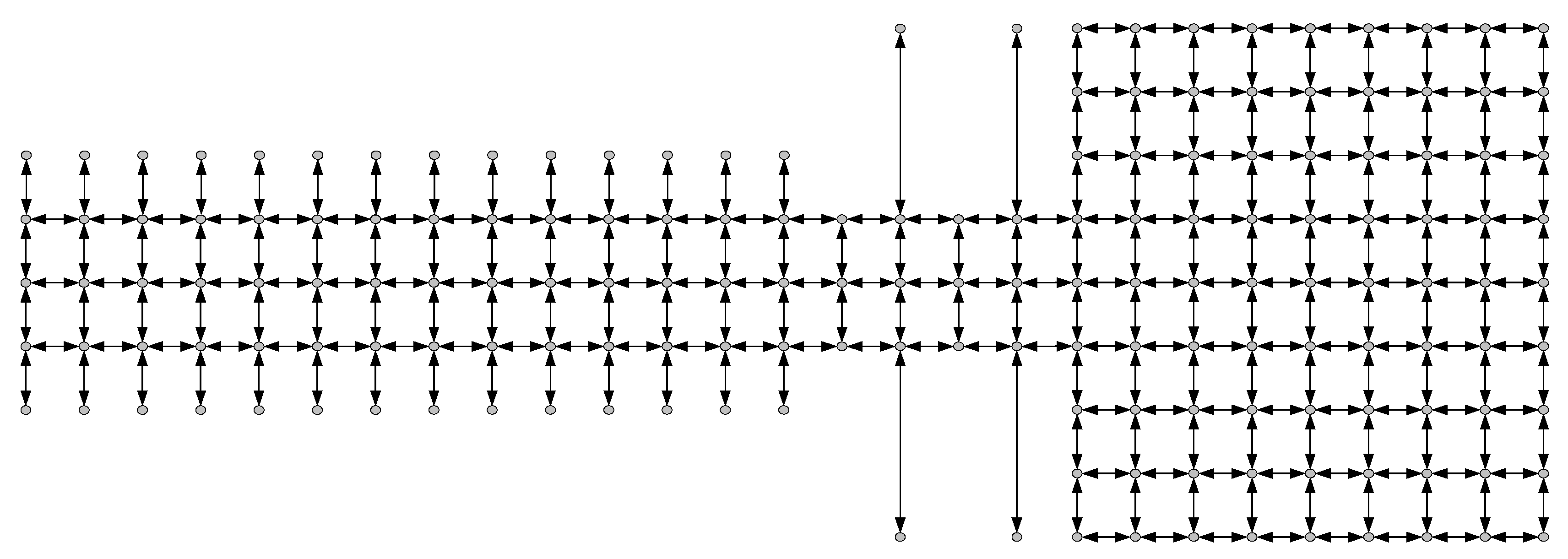
Figure 1. Factory topology map in the automated guided vehicle (AGV) system.
Electronics 09 01351 g001
Figure 2. Local grid map of AGV.
Electronics 09 01351 g002
Figure 3. Topological map of the storage area.
Electronics 09 01351 g003
Figure 4. Improved A* algorithm flow chart.
Electronics 09 01351 g004
Figure 5. Kinematics model of AGV.
Electronics 09 01351 g005
Figure 6. Common problems of AGV operation.
Electronics 09 01351 g006
Figure 7. Path planning of AGV based on the classic A* algorithm.
Electronics 09 01351 g007
Figure 8. Path planning of AGV based on the improved A* algorithm.
Electronics 09 01351 g008
Figure 9. Time-consuming comparison chart.
Electronics 09 01351 g009
Figure 10. Conflicts comparison chart.
Electronics 09 01351 g010
Figure 11. Path comparison: (a) path based on traffic rules and (b) path based on the bi-level path planning algorithm.
Electronics 09 01351 g011
Figure 12. Paths planned by the first-level path planning algorithm.
Electronics 09 01351 g012
Figure 13. AGV status during operation.
Electronics 09 01351 g013
Figure 14. Task success.
Electronics 09 01351 g014
Figure 15. Multi-AGV loading.
Electronics 09 01351 g015
Figure 16. Multi-AGV operation.
Electronics 09 01351 g016