1. Introduction
To provide Internet-of-Things (IoT) services, a variety of wireless access technologies have been developed, such as Wi-Fi [
1], Bluetooth [
2], Near Field Communication (NFC) [
3], and Zigbee [
4]. However, these technologies have suffered from radio frequency (RF) interferences, since most of those technologies use the same RF band, such as 2.4 GHz or 5 GHz. Through interference, the performance may be degraded, since many collisions frequently occur during data communications.
The Visible Lights Communication (VLC) technology [
5] has recently been proposed as one of the wireless communication technologies. VLC communication is based on lights (e.g., LED lights), and thus the corresponding RF band is completely different from the conventional wireless access technologies. Thus, VLC can reduce the RF interferences from numerous wireless channels [
6]. In addition, the most prominent feature of VLC is that it can provide more exact location information, since it is based on a particular LED light. For example, in an indoor environment with numerous LED lights, VLC can provide more precise location information, compared to the Wi-Fi technology. This is helpful for a variety of location-based IoT services.
Accordingly, VLC can be used for Internet-of-Things (IoT) services. Until now, many studies on VLC have been conducted to improve VLC functionality. Those works include the Optical Wireless Communication (OWC) [
7,
8] that was proposed to provide VLC receiving modules for mobile devices, such as smart phones. However, up to now, not enough studies on how to provide IoT services over VLC networks have been conducted. In this paper, we will address how to effectively provide IoT services in VLC networks. In particular, we will consider the ‘unidirectional’ VLC network. It is also called a hybrid VLC network that consists of the downlink channel using VLC and the uplink channel using the other wireless access communication. This is because most of the VLC receivers, such as mobile phones, cannot support the uplink VLC communication, since the uplink VLC communication requires additional processing overheads for VLC transmission.
Based on the discussion above, in this paper, we propose a framework of IoT services in uni-directional VLC networks. The applicability of bidirectional VLC, in which the downlink and uplink channels between the VLC transmitter and receiver use VLC communication, is for further study. In addition, we also propose the VLC-IoT protocol (VIP), which is an application layer protocol with session management functionality that can be used to effectively provide IoT services among IoT servers, VLC transmitters and VLC receivers in the networks.
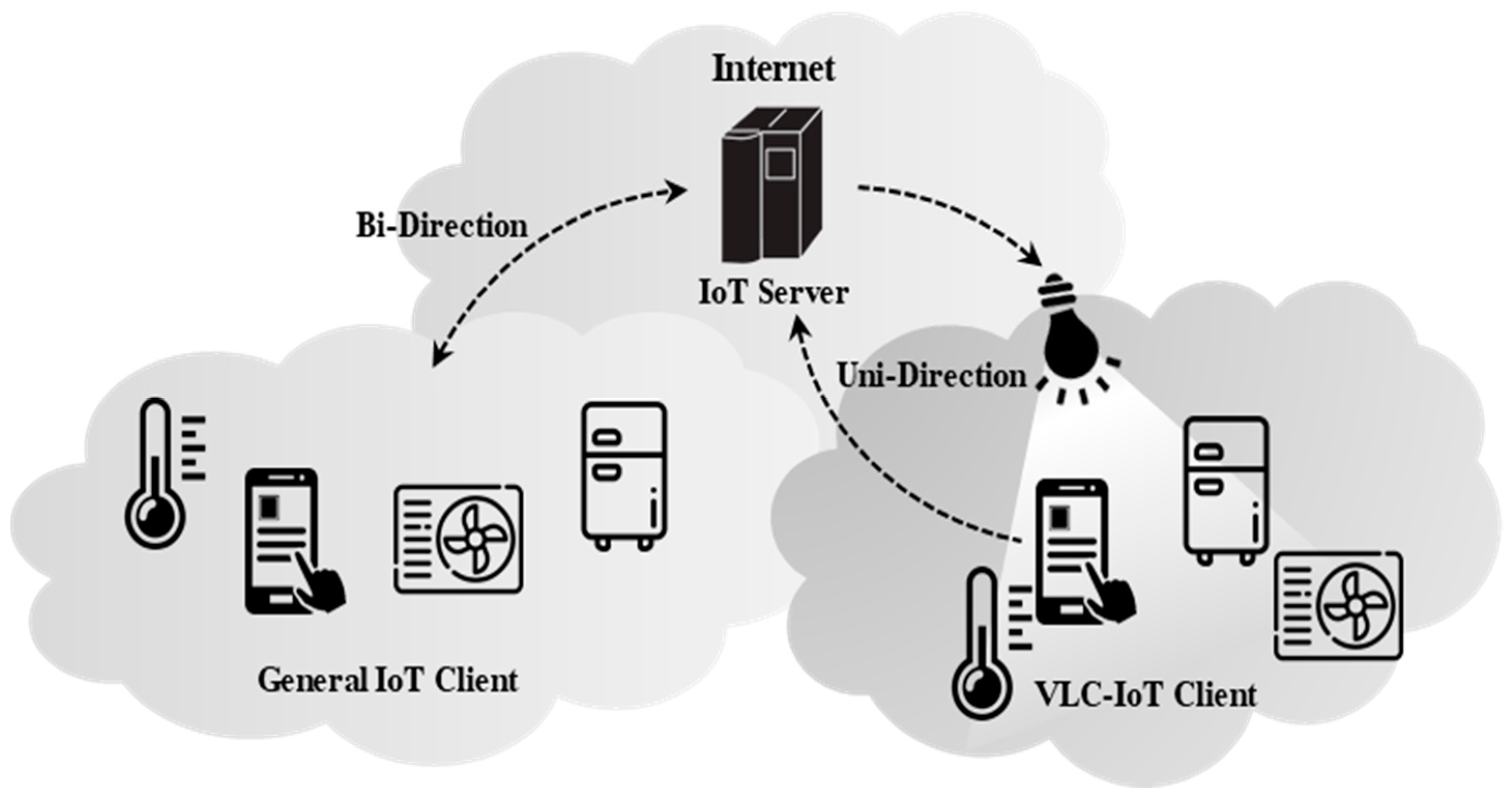
Figure 1 shows the typical examples of IoT services over VLC in the IoT networks [
9]. The general IoT network provides a bidirectional communication in which a client requests the services to IoT server, and the server will respond to the request of the client. However, in the case of a unidirectional VLC network, the VLC transmission is performed from the VLC transmitter to the VLC receiver (client), but the backward channel from the client to the IoT server (further to the VLC transmitter) will be done by using another wireless access technology. This paper focuses on the uni-directional VLC case, whereas the bi-directional VLC case may be considered for further study.
This paper is organized as follows.
Section 2 briefly summarizes the related works on VLC, which include the types of VLC transmissions (bidirectional VLC and unidirectional VLC). In
Section 3, we describe the framework of IoT services over the unidirectional VLC network and the corresponding VLC-IoT Protocol (VIP) with session management and handover operations.
Section 4 discusses the implementation and experimentations for performance analysis by using the Cooja simulator [
10].
Section 5 concludes this paper.
3. Proposed Framework and Protocol for IoT Services over Unidirectional VLC
In this paper, we propose a scheme to provide reliable VLC services and improve the data transmission performance by using session management. For this purpose, we propose a framework for the provision of IoT services over unidirectional VLC networks. Based on the framework, we also propose the VLC-IoT protocol (VIP), an application layer protocol for the delivery of VLC data in IoT networks.
3.1. Framework for IoT Services over Unidirectional VLC
Figure 3 shows the framework to provide IoT services over a unidirectional VLC network. As shown in the figure, the network consists of the following five entities: IoT server (IS), VLC gateway (VG), aggregation agent (AA), VLC transmitter (VT), and VLC receiver (VR). The detailed network configuration may be different, depending on the concerned network environment. For example, in the case of smart homes, AA may not be used, as shown in the left side of
Figure 3. In case of smart buildings, AA can be used for aggregation of the traffic from many VTs in the same floor, as shown in the right side of
Figure 3. The detailed roles of each network entity are described as follows.
3.1.1. IoT Server (IS)
IS represents a legacy server to provide the IoT services. It can be located inside or outside the VLC-IoT network, depending on the service type. IS will be connected to the VG of the target network.
3.1.2. VLC Gateway (VG)
VG is a gateway to connect the target VLC network to the Internet, and it is used to provide IoT services for the clients in the VLC-IoT network. VG will manage all VLC-IoT sessions for clients in the target network. In some cases, IS may be co-located with VG, in which VG will act as an IoT server.
3.1.3. Aggregation Agent (AA)
AA can be used to manage many LED lights (VTs) that are located in the specific floor of a large building. AA will also relay the data messages between IS and its concerned VTs to provide IoT services. In the unidirectional VLC, AA will support the uplink channel function of IoT devices (VRs) by using the existing wireless access technology, such as Wi-Fi.
3.1.4. VLC Transmitter (VT)
VT represents a LED light with the VLC transmission module. It will operate as a normal light and at the same time it can be used for data communication. When VT is powered on, it initiates the registration process with the upstream AA and, further, the VG. With the registration, an identifier will be assigned to the VT. After that, the VT will periodically send beacon messages toward VRs to facilitate the registration of VRs.
3.1.5. VLC Receiver (VR)
VR represents an IoT device with the VLC receiving module. It is a client to exploit the IoT services provided by the IS. With the registration, an identifier will be assigned to each VR. The VR identifier will helpful for IS and VG to accurately identify the VR in the VLC-IoT network. The VR can be a fixed device or a mobile device such as a smartphone. If a fixed VR uses wired communication, such as cable Internet, the VR may be connected to AA via the wired connection for the uplink channel. For the mobile VR device, the handover will be supported for service continuity.
3.2. VLC-IoT Protocol (VIP): Protocol Stack and Packet Format
Based on the framework discussed in the previous section, we propose the VLC-IoT Protocol (VIP) so as to provide effective VLC services over the unidirectional VLC networks. VIP is designed to provide reliable data communications and session management in the application layer.
3.2.1. Protocol Stack
Figure 4 shows the protocol stacks used for VIP among IS/VG, AA, VT and VR, in which we assume that IS and VG are co-located on the same equipment. VIP is an application layer protocol to provide reliable IoT services over unidirectional VLC networks between IS/VG and VR via AA and VT.
As for the underlying communication protocols, the wired communications using HTTP/TCP or CoAP/UDP will be applied between IS/VG and AA, and between AA and VT. On the other hand, the unidirectional VLC transmission will be applied to the downlink channel from VT to VR, whereas the wireless communication (e.g., Wi-Fi) will be used with CoAP/UDP for the uplink channel from VR to AA.
The functional operations of VIP include initialization (VR discovery and session establishment), data transmission (with retransmission for error recovery), and handover support (VT handover and AA handover). Detailed descriptions of each operation will be given in the subsequent sections.
3.2.2. VIP Packet Format
Figure 5 shows the generic packet format for VIP. The detailed messages and the corresponding packet formats will be described in the subsequent sections with the functional operations.
The packet format contains the following fields. Type (1 byte) defines the message type used for VIP. Total Length (3 bytes) represents the total length of this message. To identify each entity in the network, an identifier (ID) must be assigned to each entity.
In the initialization, the ID of each entity must be assigned. The sizes of IDs for VG, AA, and VT are set to 2-byte (16 bits), whereas the size of VR is set to 4-byte (32 bits) since there may be a lot of VRs in the network. The ID of VG is fixed to 0, since there is only one VG in the network. The ID of AA will be assigned by VG in the initialization, before IoT services are activated. Parent ID (2-bytes is used to indicate the identifier (ID) of the upstream entity (e.g., VG or AA) that is concerned with this message. The IDs of VT and VR are used to indicate the correspondence to this message, and the detailed use of these IDs depends on the concerned message type, which will be described in the subsequent sections.
A type-specific Header (variable) is used to contain the information that is specific to the message type. Payload (variable) represents the data contents associated with the IoT services.
3.3. Initialization Operations
It is noted that the IS/VG, AAs, and VTs can be regarded as the infrastructure equipment for VLC-based IoT services. Accordingly, in this paper, we assume that these entities have already been installed and powered on, before the IoT services are activated. It is also assumed that the corresponding IDs to those entities were also assigned before a VIP session starts. We will now focus on the VR discovery and session establishment in the initialization operations.
3.3.1. VR Discovery
Before session establishment, each VR in the network must be discovered by IS/VG.
Figure 6 shows the VR discovery operations.
For VR discovery, each VT will send beacon messages toward the promising VRs periodically. The beacon message type is set to 0, and its format is given in
Figure 7. In the beacon message, VR ID is set to 0, since the VR has not been discovered yet. The type-specific header is used to indicate the uplink ID, the access address of the upstream AA for the uplink channel. For example, when Wi-Fi is used as an uplink channel, this field is filled with the SSID of the Wi-Fi access point.
On reception of a beacon message, the VT transmits a VR Registration Request (VRR) message of type 1 to the AA through the uplink channel. The format of VRR is shown in
Figure 8A. The VRR message does not use the type-specific header, and the ID of VR is filled with 0. IDs of AA and VT will be filled with the information received from the beacon message. When AA receives the VRR message, it publishes a nonce and responds with this to VR. At the same time, the VRR message is delivered to VG. The nonce information is used to temporarily identify the VR, before allocating an ID to the VR. When the VG receives the VRR message, it transmits a VRA message of type 2 to AA in order to allocate an ID to the VR. The VRA format is shown in
Figure 8B.
The VRA message contains the type-specific header with the nonce information. The IDs of AA and VT are filled with the values received from the VRR message. On reception of the VRA message, AA sends this message to the corresponding VT. The VT then sends this message to the concerned VR through VLC. At this time, the VR compares the received nonce value and its own nonce value. If those two values are the same, the ID of VR is confirmed.
For completion of VR discovery, the VR will send the VR Registration Confirm (VRC) message of type 3 through the uplink channel to the AA, and further to the VG. The VRC message format is almost the same with that of the VRR.
3.3.2. Session Establishment
After the registration, the VR can initiate the session establishment operations to request the IoT service to the IS. In VIP, a session is established between the IS/VG and the VR via the AA and the VT.
Figure 9 shows the session establishment operations.
The VR first transmits a Session Establishment Request (SER) message of type 4 to the AA through the uplink channel to establish a session, and the AA delivers it to the VG.
Figure 10A shows the format of the SER message.
The SER message uses the type-specific header with the Session ID and VR sequence number fields. The corresponding values of these fields are given by the VR in a random or arbitrary manner. The VR sequence number represents the sequence number of data messages that are sent by the VR to the IS/VG, which will be referred to in the reliable transmission with error recovery.
On reception of the SER message, the VG will generate a Session Establishment ACK (SEA) message and responds to the VR with this message. The SEA message format is shown in
Figure 10B. The SEA message format is similar to that of the SER message, except that it uses the VG sequence number field, instead of the VR sequence number. This is because the data transmission will be bidirectional based on the half optical method between the VG and VR.
On reception of the SER message, the VR will send the Session Establishment Confirm (SEC) message of type 6, which has the same format with the SEA message. Since then, the VG and VR can begin the data transmissions in the session.
3.4. Data Transfer Operations
3.4.1. Data Transmission
After the session establishment, the VR and VG can exchange data messages with each other by using the so-called sliding window technique in the session.
Figure 11 shows an example of the data transmission operations, in which the sliding window size is set to 4.
For data transmission, the two types of messages, VLC Service Data (VSD) and VLC Service Data ACK (VSA), are used. VR or VG can send the VSD message to its peer entity for the purpose of data transmission. The VSA message is used to acknowledge the reception of VSD messages.
Figure 12A shows the VSD message format of type 7, which uses the type-specific header that is similar with the SER message.
Figure 12B shows the VSA message format of type 8. VSA uses the type-specific header to contain the selective acknowledgement information. In the figure, the cumulative ACK number field is used to report the number of well-received data. If there is data loss, the number of Gap ACK and Gap ACK fields are used to describe the detailed information on the status of data reception. When a data loss is detected from Gap ACK information, the data retransmission operation will be activated. It is noted that these mechanisms are similar to those in TCP.
3.4.2. Data Retransmission for Error Recovery
When a data loss occurs, the data retransmission will be performed. The data retransmission will be conducted in the following two cases: (1) by explicit detection of loss from Gap ACK, (2) by the pre-configured retransmission timeout.
Figure 13 shows the data retransmission operations by explicit loss detection with Gap ACK contained in the VSA message.
In the figure, the VR receives the data messages of 10,000 and 10,003 from the VG, and the data messages of 10,001 and 10,002 are lost. In this case, the VR sends the VSA message to the VG with the Gap ACK so as to indicate the data loss for the concerned data messages. Then, the VG may retransmit the concerned data messages to the VR, together with the data message of 10,004. The VR now realizes that all data messages are now in order, and it sends the VSA message with the last sequence number received well. In this example, the VG can send new three data messages of 10,005, 10,006 and 10,007.
Figure 14 shows the data retransmission operations by timeout. In the figure, the VG will activate the retransmission timer (RTO) for each data message transmission (VG-Seq: 10,000~10,003). If the corresponding ACK has not arrived via VSA message, until the RTO timer is expired, the VG retransmits the concerned data messages. In this example, the losses of data messages 10,000~10,003 were detected by the RTO timer, and thus the corresponding VSD messages were retransmitted.
3.5. Handover Operations
The proposed VIP scheme supports the two types of handovers: VT handover and AA handover. In the VT handover, a VR changes its VT to another VT that is located with the same AA by movement, whereas in the AA handover, the VR will change its AA to another AA in the network. A handover event will be detected when the VR receives a new beacon message from a new VT or AA. If the message comes from a different VT but the same AA, it means the VT handover has occurred. Otherwise, if the message comes from a different VT and a different AA, it means the AA handover has occurred. The AA handover usually needs more operations for handover support. The proposed scheme is designed to provide a fast handover so as to reduce the transmission delays that may occur by handover, with the help of the session management.
Figure 15 shows the VT handover, in which the VR changes its VT from VT1 to VT2 during the session. When the VR receives a new beacon message from VT2, the VR sends the Handover Notification (HON) message of type 9 with the ID of the new VT2. The HON message has the same format with the VSA message, except the type number. Note that the HON message will include the ACK information, as done in the VSA message. In the figure, the lost data messages of 10,002~10,005 are retransmitted after the VT handover.
Figure 16 shows the AA handover operations, in which the VR moves from AA1 to AA2. The AA handover operations are almost the same as the VT handover operations. When the VR receives the beacon message from the VT2 in the AA2 region (step 8 in the figure), it detects the AA handover. At this time, the VR sends the HON message to AA2 in step 9, and further to the VG. When the VG receives this message, it sends the VSD messages, which have not been acknowledged, to the VR via the VT (AA2).
4. Performance Analysis by Simulations
In this section, the performance analysis of the proposed scheme is described by using the Cooja simulator [
10]. The Cooja simulator is a tool used to analyze the performance of constrained networks, which is based on Contiki OS that is a light-weight OS that supports IoT devices. For simulations, we implemented the unidirectional VLC module from VT to VR by using the Cooja simulator.
4.1. Simulation Environment and Packet Analysis
Figure 17 shows the simulation environment to analyze the proposed scheme in the Cooja simulator. In the figure, the area 1 represents the network panel to show the network topology. In the network panel, each node is identified by the node ID in the network (node 1: VG, nodes 2 and 7: AA, nodes 3, 8, and 9: VT, the other nodes: VR). For description, we will use the notation of ‘type-ID’ for each node (e.g., VT-9 indicates the VT with node ID of 9). In the network configuration, VT-9 is managed by AA-7, whereas VT-3 and VT-8 are managed by the AA-2. The area 2 indicates the output panel in Cooja to show the status of each node in the network. If a node sends some data message to another node, we can see the corresponding node ID and the reception time, and so on.
Based on the simulation model, we will first analyze the packets generated during the VIP operations so as to check the validity of the simulation.
Figure 18 shows the messages generated during the VR discovery. Area 1 shows the beacon message from VT-8. This message contains AA-2 and VT-8. The VRs nearby VT-8 receive the beacon message, as shown in Area 2. The VRs will first check the AA-ID and the VT-ID. For a new beacon message, the VRs send the VRR message. Area 3 shows that AA receives the VRR message and sends a nonce value to the VR. In Area 4, we can see that VR successfully receives the nonce value. When the VG receives a VRR message, it sends the VRA message with the VR-ID to VT-8. Area 5 shows that VT-8 receives the VRA messages and sends these messages to VR over the VLC channel. In Area 6, the first VRA message is processed by VR-4. In Area 7, the VRA message is processed by VR-5. After the VRs successfully receive the VRA messages, they send the VRC messages to the VG, as shown in Area 8.
Figure 19 shows the messages generated during session establishment. In Area 1, the VRs send the SER messages with session IDs and VR sequence numbers to the VG. In Area 2, the VG receives the SER messages and creates the VG sequence numbers to be filled in the SEA message. In Area 3, VT-8 receives the SEA messages and sends them to the VRs through the unidirectional VLC channel. Area 4 shows that VR receives the SEA message and sends the responding SEC message to the VG. The SEC message is successfully processed by the VG, as shown in Area 5.
The description of the packet analysis for data transmission is omitted in this paper, since this is similar to the handover analysis, which will be described below.
Now let us consider the handover simulations.
Figure 20 shows the simulation topology for the VT handover, in which VR-4 moves from VT-8 to VT-3 during data communication.
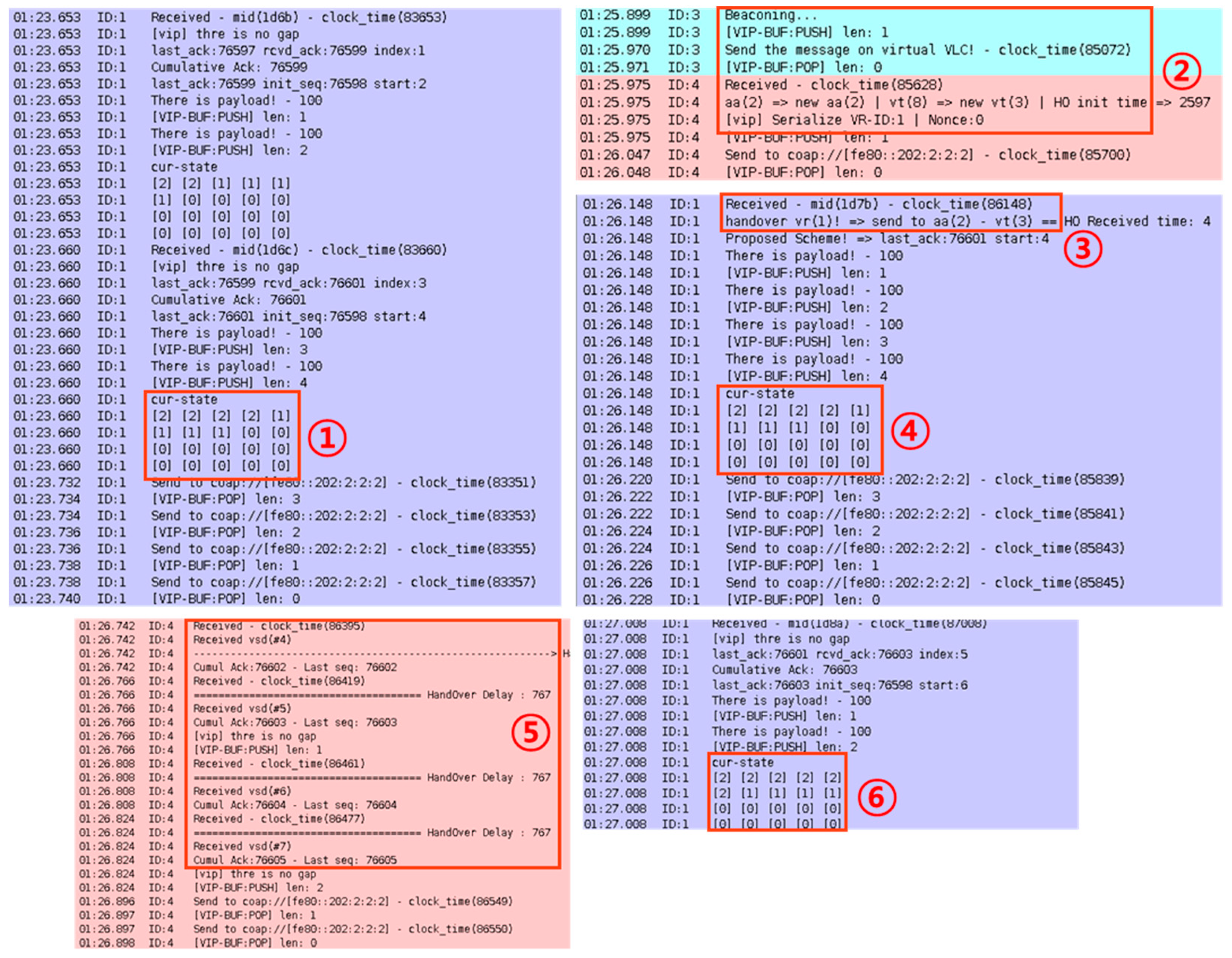
Figure 21 shows the messages generated by the VT handover of
Figure 20. For data transmission, the window size is set to 4, and the VR moves from the VT-8 region to the VT-3 region in simulation. Area 1 shows the data transmission in the VT-8 region, before VT handover. In Area 2, the VR receives the beacon message from VT-3, then it sends the HON message with VT-3 ID to the VG. In Area 3 and 4, the VG detects the VT handover, and it sends data messages to the VT-3. In Area 5, the VR receives the VSD data message and sends the VSA messages. In Area 6, the VG transmits the next data messages.
Figure 22 shows the simulation topology for the AA handover, in which VR-4 moves from the AA-2 (with VT-8) region to the AA-7 (withVT-9) region during data communication. The description of packet analysis for the AA handover is omitted in this paper.
4.2. Performance Analysis
In this section, we describe the performance analysis of the proposed VIP scheme and the existing scheme by simulations. The existing scheme represents the legacy CoAP/UDP-based VLC data delivery without session management. In the existing scheme, the window size is not used for data transmission, and thus the existing scheme can be regarded as the use of a widow size of 1.
We will compare the two candidate schemes in terms of throughput, total transmission delays, and handover delays under a variety of network environments.
4.2.1. Throughput
Figure 23 shows the comparison of throughputs for the existing and proposed schemes, in which the throughput represents the average number of packets processed for every second. In the proposed scheme, the window size is set to 4, and the VG transmits the data messages for one minute. From the figure, we see that the proposed scheme provides better throughputs than the existing scheme. The existing scheme gives the maximum throughput of 2.6 packets per second, whereas the proposed scheme provides the maximum throughput of 5.9 packets per second. This performance gain of the proposed VIP scheme comes from the session management and reliable data transmission.
4.2.2. Total Transmission Delays
Figure 24 shows the total transmission delays of candidate schemes for different numbers of packets, in which the delay values are shown with the maximum, minimum, and average values over 10 experiments for each candidate scheme.
In the figure, we see that all candidate two schemes tend to give larger delays, as the number of packets increases. However, the proposed scheme provides lower delays than the existing scheme. Such gaps of performance between proposed and existing schemes gets larger, as the number of packets increases. In the case of 20 packets, the delay gap between two schemes is about 4330 msec, while in the case of 100 packets, the delay gap is about 22,864 msec. This is because the proposed scheme provides sliding window-based data transmissions, which are helpful to reduce total transmission delays. In the meantime, the existing scheme does not support the session management, and thus the effective data transmission cannot be performed, compared to the proposed scheme.
Figure 25 shows total transmission delays in the lossy network environment, in which some data messages over the unidirectional VLC will be lost. In the figure, we see that the proposed scheme can provide lower delays than the existing scheme, and the performance gaps tend to get larger, as the VLC data loss rate increases. In particular, the performance of the existing scheme was severely degraded when the data loss rate was greater than 35% in the network. This is because the proposed scheme provides the error recovery scheme with retransmission and session management functions. However, the existing scheme cannot support the error recovery and session management, and thus the data transmission will just rely on the CoAP delivery between two network entities. This may induce large transmission delays, in particular, in the lossy VLC networks.
Figure 26 shows the total transmission delays (min, max, average) of the proposed VIP scheme for different window sizes, in which total transmission delays are measured for 100 data messages. In the figure, when the window size is 1~4, we can see that the total transmission delays are significantly reduced, whereas the delays are almost the same for the window sizes of greater than 4. Moreover, the delay variations between max and min get larger as the window size increases. This is because too large window size tends to induce too much data traffic to be supported by the proposed VIP scheme. This implies that the window size of 4 is a reasonable value for our experiment.
4.2.3. Handover Delays
Figure 27 shows the VT handover delays, in which the handover delay is measured by the gap between the time that the VR sends the HON message to the VG for handover notification and the time that the VR begins to receive the data messages by way of the newly attached VT in the network. In the figure, we see that the proposed scheme can reduce the VT handover delays significantly, compared to the existing scheme. This is because the proposed scheme provides the fast handover mechanism scheme, whereas in the existing scheme the data transmission must begin if a handover occurs.
Figure 28 gives a more detailed analysis of packets generated and processed during VT handover, in which the handover occurs at the time of 3.03 s. In the proposed scheme, much more data packets are generated and processed effectively, compared to the existing scheme. This is because the proposed scheme performs the handover notification as soon as the VR receives a new beacon message.
Figure 29 shows the AA handover delays, in which the handover delay is measured by the gap between the time that the VR sends the HON message to the VG for handover notification and the time that the VR begins to receive the data messages by way of the newly attached AA in the network. In the case of AA handover, the IP address allocation delay using the Dynamic Host Configuration Protocol (DHCP) [
21] will be added to the handover delay, since the AA handover contains the change of the IP addresses concerned with the AAs. It is noted that AA handover delays are relatively large compared to VT handover delays. In the figure, we see that the proposed scheme gives smaller VT handover delays than the existing scheme.
Figure 30 gives a more detailed analysis of packets generated and processed during AA handover, in which the handover occurs at the time of 3.23 s. In the figure, we see that the proposed scheme performs the AA handover operations more effectively that the existing scheme. The proposed scheme tends to give better throughputs in the AA handover, compared to the existing scheme. We note that the y-values for the simulation time of 30~32 (before handover) are constant because the VR can receive the new data messages from the changed AA (after handover).
5. Conclusions
In this paper, we have so far proposed a framework to provide IoT services based on unidirectional VLC networks, together with the VIP protocol including session management and reliable data transmissions. The proposed scheme is helpful in providing reliable delivery of IoT services over VLC networks with throughput enhancement. We also proposed the fast handover schemes for VT and AA handovers. By the implementation and experimentations using the Cooja simulator, we see that the proposed VIP scheme can provide higher throughput and lower data transmission and handover delays than the existing CoAP-based scheme. This is because the proposed scheme uses session management, reliable data delivery, and fast handover operations, compared to the existing scheme.
For further study, some more issues need to be investigated. The proposed scheme needs to be analyzed in more detail with experimentations over real testbed networks. In particular, the proposed IoT-VLC scheme may be compared to the direct Wi-Fi scheme without using the VLC transmission in the performance analysis.


