Review

GaN Single Crystalline Substrates by Ammonothermal and HVPE Methods for Electronic Devices

Institute of High Pressure Physics Polish Academy of Sciences, Sokolowska 29/37, 01-142 Warsaw, Poland
*
Author to whom correspondence should be addressed.
Electronics 2020, 9(9), 1342; https://doi.org/10.3390/electronics9091342
Submission received: 6 July 2020 / Revised: 6 August 2020 / Accepted: 15 August 2020 / Published: 19 August 2020
(This article belongs to the Special Issue Micro- and Nanotechnology of Wide Bandgap Semiconductors)

Abstract

:
Recent results of GaN bulk growth performed in Poland are presented. Two technologies are described in detail: halide vapor phase epitaxy and basic ammonothermal. The processes and their results (crystals and substrates) are demonstrated. Some information about wafering procedures, thus, the way from as-grown crystal to an epi-ready wafer, are shown. Results of other groups in the world are briefly presented as the background for our work.

1. Introduction

It seems that the lack of native wafers, of high structural quality, appropriate size, and electric properties, limits the development of GaN-based electronic devices. Highly conductive substrates are required for preparing high-power vertical transistors (i.e., the Metal-Oxide Semiconductor Field-Effect Transistor; MOSFET) or Schottky diodes. Semi-insulating GaN (SI-GaN) wafers are needed for preparing lateral devices, i.e., high electron mobility transistors (HEMTs). The nitride community is still working on the best technology for crystalizing GaN and fabricating GaN substrates. Growing GaN is, however, a rather challenging process. The compound melts at a very high temperature (exceeding 2200 °C) and the nitrogen pressure necessary for congruent melting is expected to be higher than 6 GPa [1,2,3]. GaN should, thus, be grown by other techniques requiring a lower pressure and temperature. Crystallization from the gas phase or solution has to be applied. Today, three technologies are mainly developed: sodium flux, ammonothermal, and halide vapor phase epitaxy (HVPE). The last one is the most popular one and developed by the industry. HVPE-GaN wafers are fabricated by such Japanese companies like SCIOCS by Sumitomo Chemical [4], Sumitomo Electric Industries (SEI) [5], Mitsubishi Chemical Corporation (MCC) [6], and Furukawa Metals [7]. HVPE-GaN substrates are also manufactured by Chinese Nanowin [8] and EtaResearch [9] as well as by French Lumilog by Saint Gobain [10]. All these companies sell highly conductive and semi-insulating 2-inch and even 4-inch HVPE-GaN substrates. They are all prepared from HVPE-GaN grown on foreign seeds, which lower the product’s structural quality.
Companies and research institutes working on the ammonothermal method are the following: Institute of High Pressure Physics Polish Academy of Sciences (IHPP PAS; Warsaw, Poland) [11], SixPoint Materials Inc. (Buellton, CA, USA) [12], University of California Santa Barbara (Santa Barbara, CA, USA) [13], University of Stuttgart (Stuttgart, Germany), University of Erlangen (Erlangen, Germany) [14], MCC (Tsukuba, Japan) [15], Tohoku University (Sendai, Japan) [16], and Kyocera (formerly Soraa, Inc., Santa Barbara, CA, USA/Kyoto, Japan) [17]. Two-inch as well as smaller ammonothermal GaN (Am-GaN) substrates are sold in limited quantities only by IHPP PAS [18].
The sodium flux method is mostly developed at Osaka University [19] and their GaN crystals or substrates are not available on the market. It should be, however, remarked that a 6-inch sodium flux crystal has already been demonstrated [20].
In this paper, the results of GaN bulk growth performed in Poland, at IHPP PAS, are briefly presented. Two technologies are described: HVPE and ammonothermal. Their advantages, disadvantages, and challenges are analyzed. It should be noted that no one has demonstrated a real bulk GaN crystal yielding several tens of wafers per boule. The technology allowing to reach this goal has also not been presented. The reasons for the lack of thick GaN are explained in this paper. During a growth process performed in a chosen vertical direction, crystallization occurs also in lateral directions. This, together with an anisotropy of growth, is the reason why obtaining truly bulk GaN is so difficult, even if native seeds of high structural quality are used. A few solutions that could help to further develop bulk GaN growth are, however, shown. Some information about wafering procedures, thus, the way from an as-grown crystal to an epi-ready wafer, are also demonstrated. Results presented by other groups crystallizing GaN are used as reference. The beginning of the paper focuses on the requirements for GaN substrates. Then, HVPE-GaN crystallized on foreign seeds is discussed. In the next step, the ammonothermal method is presented and analyzed. The recent progress is shown. At the end of this paper, new results of HVPE-GaN grown on native Am-GaN seeds are discussed.

2. Requirements for GaN Substrates

The most important property of a GaN substrate is its structural quality. The threading dislocation density (TDD) should be as low as possible and uniform across a wafer. In the case of GaN, the (0001) surface (c-plane) is mainly considered. Today, the lowest value of TDD, of the order of 104 cm−2, is reported for Am-GaN [21,22,23]. This value is two orders of magnitude lower than TDD in commercially available HVPE-GaN wafers. It is well known that TDD is well correlated with the etch pit density (EPD) [24]. In fact, EPD is a parameter much more often used when describing a GaN wafer and its properties. It is much easier and cheaper to etch a surface of a substrate, count the pits and determine their density, than to analyze dislocations by transmission electron microscopy (TEM). Additionally, if TDD is of the order of 106 cm−2 or lower, it is difficult to detect dislocations by TEM. Therefore, in this paper, we refer only to values of EPD. When the (0001) GaN surface is etched three kinds of pits can be distinguished: large, medium, and small. According to Weyher et al. [24], these pits are correlated to screw, mixed, and edge dislocations, respectively. The data collected for Am-GaN and HVPE-GaN grown on Am-GaN seeds show that the density of large pits (screw dislocations) varies from 100 to 101 cm−2. In turn, the density of medium and small pits (mixed and edge dislocations) is at the level of 5 × 104 cm−2 [23,25]. Figure 1 allows to compare EPD on the c-plane surface of a typical Am-GaN wafer from IHPP PAS and commercially available HVPE-GaN.
The low EPD is not the most important feature of GaN substrates. Flatness of crystallographic planes (see Figure 2) seems to be more important. It guarantees a uniform off-cut of the substrate, which, in turn, allows for epitaxial growth of any future device structure with an atomic step flow. Generally, the variation of off-cut across the surface should not be higher than 0.1°. This is the main and basic requirement for promoting the step flow, controlling the composition of ternary alloys in the device layers, as well as the incorporation of dopants and unwanted impurities [26,27,28]. For a 2-inch wafer, the required value of radius of curvature should be higher than 15 m. In commercially available HVPE-GaN substrates, the radius is at the level of 5 m, but in the case of 2-inch Am-GaN, it is usually around 30 m. The off-cut uniformity is also important for preparing an epi-ready surface of a substrate. This is also one of the most important requirements for a wafer. The surface, usually (0001) in the case of GaN, should be epi-ready, without any subsurface damage, with the value of the root means square (RMS) lower than 0.1 nm, and clean (see Figure 3).
Last but not least, there is a requirement for a GaN wafer regarding its free carrier concentration. A high, of the minimum order of 1018 cm−3, and uniform value is needed if the substrate will be used for a vertical device (e.g., MOSFET). This allows to fabricate, in a relatively easy way, a stable and low-resistance ohmic contact to the bottom part of the substrate. Obviously, SI substrates with resistivity higher than 108 Ω∙cm at room temperature (RT) are needed for lateral devices.

3. HVPE-GaN Wafers—Crystallization on Foreign Seeds

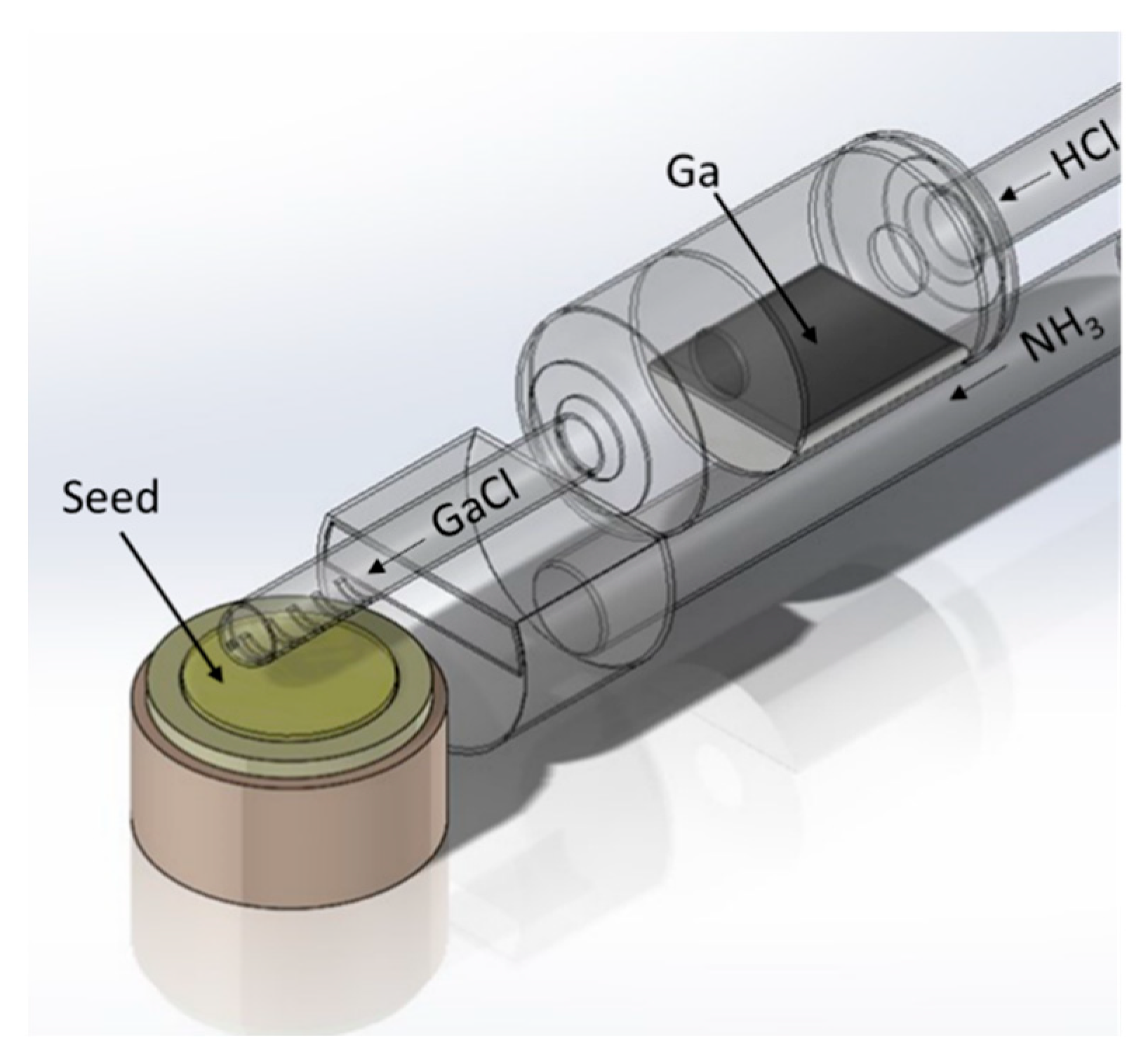
HVPE is a method of crystallization from gas phase. Figure 4 represents a scheme of a typical HVPE horizontal quartz reactor used at IHPP PAS. In a quartz tube, there are two zones with different temperatures: (i) low (800–900 °C), where hydrochloride (HCl) reacts with gallium (Ga) to synthesize gallium chloride (GaCl) and (ii) high (1000–1100 °C), where GaCl reacts with ammonia (NH3) and GaN is crystallized. All reactants are transported by a carrier gas (N2, H2, Ar, He, or their mixtures). The temperature is set with a multi-zone resistive canthal-based heater. In many cases, the resistive heating of the growth zone is replaced by RF heating. Details of such a reactor configuration were presented in many papers, e.g., [23,29,30]. Thermodynamics of GaN crystal growth process is well described in References [31,32].
The HVPE technology demonstrates two great advantages: (i) a relatively high growth rate, which exceeds 100 μm/h and (ii) a possibility to crystallize high-purity material; concentrations of unintentional dopants (silicon, oxygen, iron) are generally of the order of 1016 cm−3 or even lower. A doping process with germanium or silicon to achieve highly conductive crystals as well as with carbon or iron for SI ones is well recognized and described in the literature, e.g., [33,34,35,36,37]. The main crystallographic growth direction in the HVPE technology is [0001] (the c-direction). GaN is predominantly crystallized on a foreign seed. It is either a gallium arsenide (GaAs) substrate with a low-temperature buffer layer of GaN or a metal-organic vapor phase epitaxy (MOVPE) GaN on sapphire template [38,39]. GaN crystallized on GaAs consists of areas (e.g., arranged in stripes) of high (108 cm−2) and low (5 × 104 cm−2) EPD [40,41]. Thus, the (0001) surface of a GaN substrate (after chemical etching of GaAs) is neither macroscopically uniform nor flat, which makes it impossible to prepare it to an epi-ready state. The bending of crystallographic planes is not observed thanks to similar thermal expansion coefficients of GaN and GaAs as well as the existence of inversion domains that reduce stress in GaN [38].
As mentioned earlier, the second kind of seeds are MOVPE-GaN/sapphire templates [39,42,43]. In this case, stress induced by the difference in thermal expansion coefficients of new-grown thick HVPE-GaN and sapphire results in a well-controlled self-separation of GaN during the cooling process. This way, free-standing (FS) crystals are obtained. Substrates prepared from them will have macroscopically flat c-plane surfaces, uniform EPD of the order of 5 × 106 cm−2, but bent crystallographic planes. The last results from the difference between the lattice constants and thermal expansion coefficients of sapphire and GaN. The value of the bowing radius of crystallographic planes of a typical GaN substrate does not exceed 10 m. It is not possible to prepare an epi-ready surface with a uniform off-cut. The substrates are plastically deformed and have dislocation bundles creating a cellular network [44].
In the authors’ opinion, the HVPE technology requires a fresh approach. The only way to further develop GaN substrates is GaN-on-GaN crystallization. Since there are no native HVPE-GaN seeds of high structural quality, the ones prepared by the ammonothermal method can be very useful.

4. Ammonothermal Crystal Growth of GaN

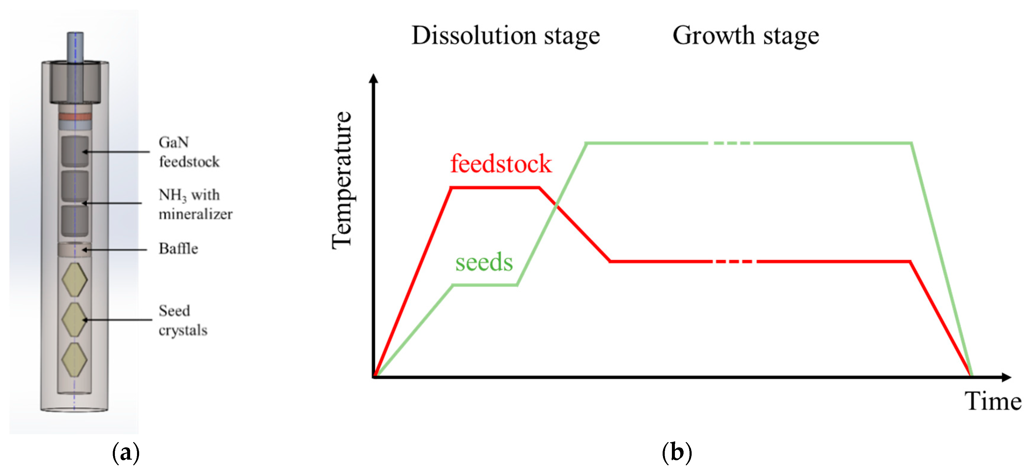
The scheme of the ammonothermal growth is the following: polycrystalline GaN (feedstock) is dissolved in supercritical ammonia enriched with mineralizers in the first zone of a high-pressure autoclave. The dissolved feedstock is transported to the second zone, where the solution is supersaturated and crystallization of GaN on native seeds takes place. An appropriate temperature gradient applied between the dissolution and crystallization zones enables the convective mass transport. Mineralizers are added to ammonia in order to accelerate its dissociation and enhance the solubility of GaN. The growth is proceeded in a different environment: basic or acidic, depending on the type of mineralizer. The ammonobasic process makes use of alkali metals or their amides, while in ammonoacidic growth, halide compounds are present. A negative temperature coefficient of solubility is observed in the ammonobasic approach [45,46]. As a consequence, the chemical transport of GaN is directed from the low-temperature solubility zone (with the feedstock) to the high-temperature crystallization one (with the seeds). The pressure of ammonia in the reactor is usually between 100 and 600 MPa and the typical growth temperature is in the range 400–750 °C [47].
Schemes of the high-pressure autoclave and a time-temperature relation of the two temperature zones applied for the basic ammonothermal crystallization developed at IHPP PAS are presented in Figure 5a,b, respectively. Red and green curves (see Figure 5b) represent, respectively, the temperature of the feedstock and growth zones. At the beginning, the zone with feedstock is heated and the material starts to dissolve in ammonia. Herein, the feedstock temperature is higher than the temperature of the crystal growth zone. During the dissolution stage, a back etching process occurs; the seeds are etched and they couple with the solution; a full contact is maintained between the surfaces of the GaN seeds and ammonia. Then, the crystal growth zone is heated to a temperature higher than that in the feedstock zone. In turn, the temperature of the feedstock zone decreases and the crystal growth starts. After a few months, the autoclave is cooled down, ammonia is released, and the crystals can be removed.
The basic ammonothermal growth at IHPP PAS consists of two parts [11]: (i) increase of the size of the seeds; they can be gradually enlarged (in diameter) by taking advantage of the lateral growth phenomena in non-polar and/or semi-polar directions and (ii) seed multiplication, which is concentrated on crystallization mainly in the vertical direction (in the [000-1] direction), after the growth process, the crystals are sliced perpendicularly to the growth direction and they can either increase the population of seeds used for subsequent growth runs or be subject to the wafering process (substrate fabrication). It should be remarked that the crystallization in the [0001] direction is treated as parasitic with an unstable morphology. In order to avoid the growth in this direction, specially prepared holders are used for the seeds. As a result, the (000-1) surface or side surfaces (non-polar and semi-polar) can be exposed for growth, while the (0001) face is always masked.
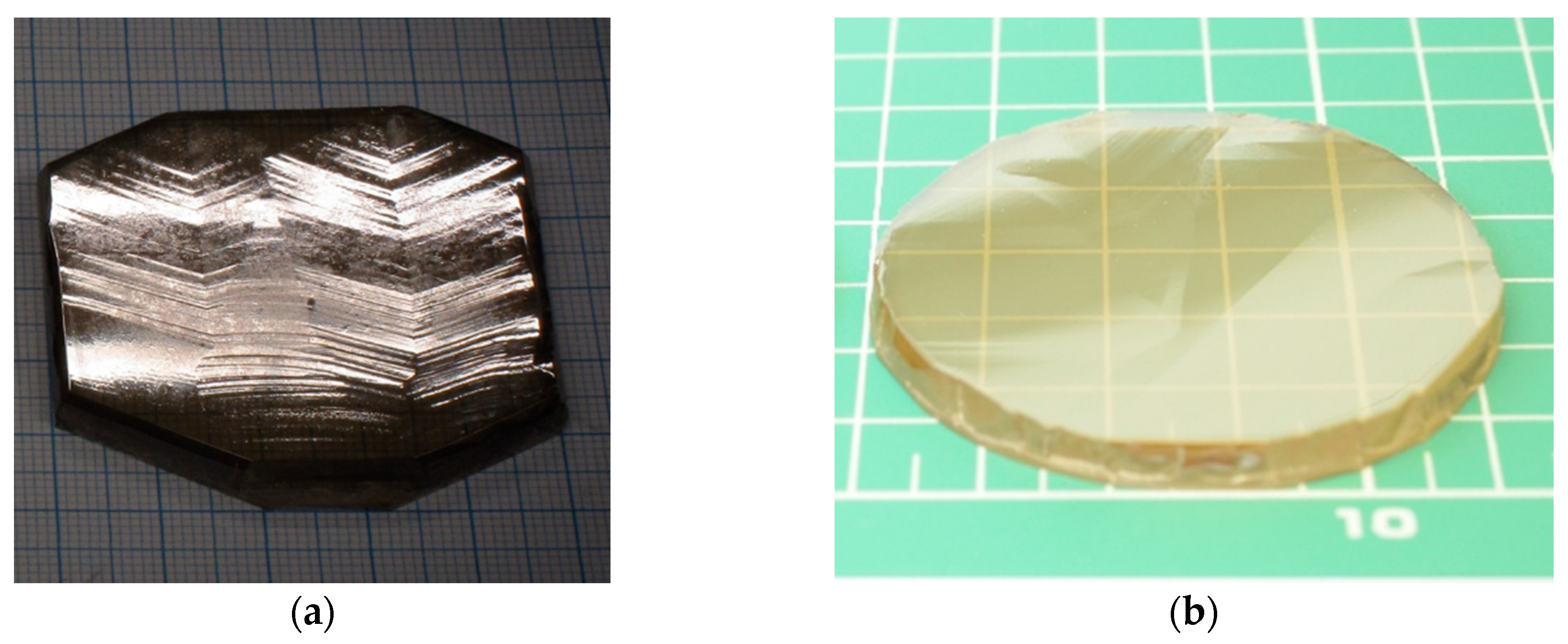
One of the most important factors limiting Am-GaN growth in the [000-1] direction (seed multiplication) is associated with the anisotropy of growth as well as crystallization that occurs in the lateral directions at the edges of the crystal. It was shown [11] that the kinds and concentrations of impurities incorporated into GaN growing on the non-polar (11–20) and (10–10) facets and on the (000-1) plane are vastly different. This causes stress and finally leads to a plastic deformation of the growing Am-GaN crystals and appearance of cracks close to the edges [11]. Changing the shape of a seed from an irregular (hexagonal) to a round one (see Figure 6) as well as masking its edges with a metal border allowed us to grow stress-free and crack-free GaN. Both the formation of side facets as well as uncontrolled growth in the lateral directions were hindered. The border effectively counteracts the crystallization in all unwanted lateral directions. Only one facet, the (000-1) plane, was crystallized. It should be noted that it is much easier to provide a metal border around the growing crystal when the seed is round. Therefore, there were no cracks visible in the round-shaped crystals. Applying this new shape allowed to increase the yield of an ammonothermal crystal growth process. Before, cracks from the edges had been able to propagate to the center of a crystal during wafering procedures. The quantity of substrates obtained from crystals had been low. Thus, the lack of cracks at the edges seems very important from the point of view of GaN substrate production. It should be noted that each crystal after the growth process is subject to a significant mechanical treatment. Firstly, slicing is performed, and the Am-GaN seed is retrieved. It can be re-used in an ammonothermal crystallization run. In turn, the new-obtained crystal is misoriented and ground. Then, it is cut into a round shape. The primary and secondary flats are formed. Furthermore, edge grinding is performed. Next, the crystal is lapped and polished. At the end, its (0001) surface is prepared to an epi-ready state by chemo-mechanical polishing (CMP) and cleaning.
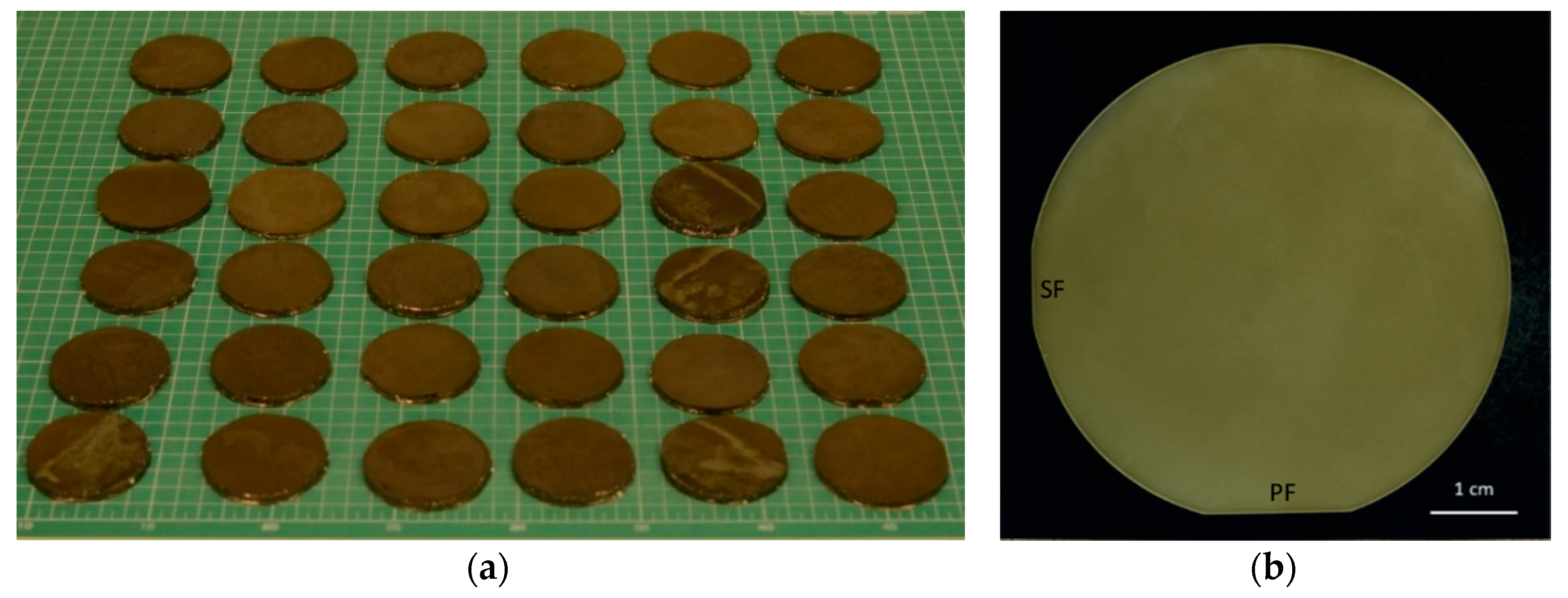
Today, one ammonothermal growth process allows to obtain a few tens of crystals with a diameter larger than 2.1-inch (see Figure 7a) and of high structural quality. This, in turn, enables to fabricate high structural quality (crystallographically flat and with low EPD) 2-inch GaN wafers (see Figure 7b). Unintentionally doped Am-GaN is n-type with free carrier concentration in the range 1 × 10¹⁸ – 2 × 1019 cm−3 [11]. The main unintentionally incorporated donor is oxygen. No intentional n-type doping is performed. Doping with Mn allows to compensate the oxygen donors and crystallize material with high resistivity (exceeding 1012 Ω∙cm at 300 °C) [11].

5. HVPE-GaN on Native Ammonothermal GaN Seeds

One of the important disadvantages of the ammonothermal crystal growth process is the low growth rate. The average value in the [000-1] direction is between 1 and 2 µm/h. Thus, as already mentioned, the ammonothermal method can be used as the source of seeds for HVPE growth. The first results of such a hybrid approach: HVPE-GaN growth on Am-GaN, were presented by IHPP PAS in 2013 [48]. Then, similar work was shown by MCC [49], and later, many other papers were published. They are summarized in References [23,50]. The growth of unintentionally doped HVPE-GaN on an Am-GaN seed proceeds in a hillock mode (see Figure 8a) with an average rate higher than 100 µm/h. The very high structural quality of an Am-GaN seed can be preserved in an HVPE layer (see Figure 8b). Doping processes performed to obtain highly conductive crystals (silicon or germanium) or SI ones (iron, carbon, or manganese), were also examined for HVPE-GaN grown on Am-GaN seeds. Crystals of high structural quality and required electrical properties were obtained. The free carrier concentration exceeded 1 × 1019 cm−3 [50]. It should be mentioned that in the case of highly resistive HVPE-GaN crystals doped with carbon or manganese, resistivity higher than 109 Ω∙cm at 300 °C was detected [37]. It is a very important result, since the operating temperature of high power-high frequency electronic devices based on SI-GaN substrates is at least 300 °C.
It was observed that during the homoepitaxial crystallization of HVPE-GaN in the [0001] direction the non-polar and semi-polar growth of “wings” (laterally-grown material) leads to the formation of large stress close to the edges of the growing crystal. The reason for this is a different incorporation of dopants (mainly oxygen) into HVPE-GaN grown in the [0001] than in lateral directions. This leads, in turn, to different lattice parameters of the crystallized material [23,51,52]. The stress from the edges is much more significant than the one generated by the lattice mismatch between the seed and the deposited layer. Avoiding lateral growth during crystallization in the [0001] direction seems essential for developing the GaN bulk growth technology.
Like in the case of the ammonothermal process, growth in the lateral directions on the edges of the seed can also be eliminated in HVPE by using a metal ring (e.g., molybdenum). It increases the dissociation of ammonia. The supersaturation close to the edges of the crystal with the ring decreases. No growth takes place in the lateral directions. Unfortunately, the side facets are still formed. The main issue is to find such growth conditions that will allow to form only the side facets that grow faster than the material in the [0001] direction. Then, they will disappear and the crystal will increase its lateral size by growing only in the [0001] direction. According to a hypothesis by Professor Zlatko Sitar from North Carolina State University (USA) [53], such conditions may be achieved by controlling the thermal field around a crystal. It has to reach its final shape by adapting to this field rather than taking the hexagonal habit. The equilibrium shape can be overpowered by a proper design of the thermal field. In this case, the crystal will follow the thermal field and grow in a direction perpendicular to the isotherms. The idea is schematically shown in Figure 9. Such an approach was presented by HexaTech for aluminum nitride (AlN) growth by physical transport deposition (PVT) [54]. Obviously, the formation of supersaturation in the PVT and HVPE methods varies significantly. The supersaturation is the difference of thermodynamic potentials at the interface between a crystal and its environment. In the case of PVT it is almost unambiguous with the temperature distribution on the growing surface. In HVPE, reactions of all vapor species have to be considered. It should, however, be stated that if the equilibrium crystal shape of GaN can be overcome, it will be a transformative achievement for the HVPE technology. It has never been demonstrated before and will allow to grow true bulk GaN crystals of high purity, eventually yielding several tens of wafers per boule. To this day, the formation of side facets has not been defeated and they are still created during HVPE-GaN growth in the [0001] direction. In spite of this, MCC has already demonstrated 4-mm-thick HVPE-GaN-on-Am-GaN [22] and IHPP PAS showed 3-mm-thick HVPE-GaN-on-Am-GaN (see Figure 9b) [55].

6. Conclusions

The growth of high structural quality bulk GaN crystals can only be performed using GaN-on-GaN technology. Today, the main method for mass fabrication of GaN crystals is HVPE. This is due to its high growth rate and purity. The process repeatability is also the highest. Ammonothermal method can provide seeds for HVPE growth. However, if the ammonothermal technology is improved, it will become a great competitor for HVPE. It should be remembered that during one ammonothermal process, a few tens of crystals can be grown. Table 1 summarizes the advantages and disadvantages of the two methods presented in this paper. Most probably, the economy will decide which technology will be applied in the future.

Author Contributions

K.G.—crystal growth experiments, characterization, preparing the manuscript; P.J., crystal growth experiments, characterization; A.S.—wafering, characterization; M.B.—supervision, review and editing; M.I.—review and editing. All authors have read and agreed to the published version of the manuscript.

Funding

This research was supported by TEAM TECH program of the Foundation for Polish Science co-financed by the European Union under the European Regional Development Fund (POIR.04.04.00-00-5CEB/17-00) as well as by the Polish National Science Center through project No. 2018/29/B/ST5/00338.

Acknowledgments

The authors are grateful to Tomasz Sochacki, Boleslaw Lucznik, and Michal Fijalkowski for helpful scientific discussions.

Conflicts of Interest

The authors declare no conflict of interest.

References

  1. Utsumi, W.; Saitoh, H.; Kaneko, H.; Watanuki, T.; Aoki, K.; Shimomura, O. Congruent melting of gallium nitride at 6 GPa and its application to single-crystal growth. Nat. Mater. 2003, 2, 735. [Google Scholar] [CrossRef] [PubMed]
  2. Porowski, S.; Sadovyi, B.; Gierlotka, S.; Rzoska, S.J.; Grzegory, I.; Petrusha, I.; Turkevich, V.; Stratiichuk, D. The challenge of decomposition and melting of gallium nitride under high pressure and high temperature. J. Phys. Chem. Solids 2015, 85, 138–143. [Google Scholar] [CrossRef] [Green Version]
  3. Porowski, S.; Sadovyi, B.; Karbovnyk, I.; Gierlotka, S.; Rzoska, S.J.; Petrusha, I.; Startiichuk, D.; Turkievich, V.; Grzegory, I. Melting of tetrahedrally bonded semiconductors:“anomaly” of the phase diagram of GaN? J. Cryst. Growth 2019, 505, 5–9. [Google Scholar] [CrossRef]
  4. GaN Substrates. Available online: https://www.sciocs.com/english/products/GaN_substrate.html (accessed on 18 August 2020).
  5. GaN Substrates. Available online: https://global-sei.com/sc/products_e/gan/ (accessed on 18 August 2020).
  6. GaN Wafer (GaN substrate). Available online: https://www.m-chemical.co.jp/en/products/departments/mcc/nes/product/1201029_9004.html (accessed on 18 August 2020).
  7. Electronic Materials. Available online: https://www.furukawakk.co.jp/e/business/material/ (accessed on 18 August 2020).
  8. Suzhou Nanowin Science and Technology. Available online: http://shopen.nanowin.com.cn (accessed on 18 August 2020).
  9. Eta Research. Available online: http://www.etaresearch.com/ (accessed on 18 August 2020).
  10. Free Standing GaN Substrates. Available online: https://www.lumilog.com/products/free-standing (accessed on 18 August 2020).
  11. Zajac, M.; Kucharski, R.; Grabianska, K.; Gwardys-Bak, A.; Puchalski, A.; Wasik, D.; Litwin-Staszewska, E.; Piotrzkowski, R.; Domagala, J.Z.; Bockowski, M. Basic ammonothermal growth of Gallium Nitride—State of the art, challenges, perspectives. Prog. Cryst. Growth Charact. Mater. 2018, 64, 63–74. [Google Scholar] [CrossRef]
  12. Hashimoto, T.; Letts, E.R.; Key, D.; Jordan, B. Growth of bulk GaN crystals. Jpn. J. Appl. Phys. 2019, 58, SC1005. [Google Scholar] [CrossRef]
  13. Pimputkar, S.; Kawabata, S.; Speck, J.S.; Nakamura, S. Improved growth rates and purity of basic ammonothermal. J. Cryst. Growth 2014, 403, 7. [Google Scholar] [CrossRef]
  14. Schimmel, S.; Duchstein, P.; Steigerwald, T.G.; Kimmel, A.-C.L.; Schlücker, E.; Zahn, D.; Niewa, R.; Wellmann, P. In situ X-ray monitoring of transport and chemistry of Ga-containing intermediates under ammonothermal growth conditions of GaN. J. Cryst. Growth 2018, 498, 214–223. [Google Scholar] [CrossRef]
  15. Mikawa, Y.; Ishinabe, T.; Kawabata, S.; Mochizuki, T.; Kojima, A.; Kagamitani, Y.; Fujisawa, H. Determination of absolute value of quantum efficiency of radiation in high quality GaN single crystals using an integrating sphere. Proc. SPIE 2015, 9363, 936302. [Google Scholar]
  16. Bao, Q.; Hashimoto, T.; Sato, F.; Hazu, K.; Saito, M.; Kagamitani, Y.; Ishinabe, T.; Kayano, R.; Tomida, D.; Qiao, K.; et al. Acidic ammonothermal growth of GaN crystals using GaN powder as a nutrient. CrystEngComm 2013, 15, 5382–5386. [Google Scholar] [CrossRef]
  17. Ehrentraut, D.; Pakalapati, R.T.; Kamber, D.S.; Jiang, W.; Pocius, D.W.; Downey, B.C.; McLaurin, M.; D’Evelyn, M.P. High quality, low cost ammonothermal bulk GaN substrates. Jpn. J. Appl. Phys. 2013, 52, 08JA01. [Google Scholar] [CrossRef]
  18. Institute of High Pressure Physics. Available online: www.unipress.waw.pl (accessed on 18 August 2020).
  19. Mori, Y.; Imade, M.; Maruyama, M.; Yoshimura, M.; Yamane, H.; Kawamura, F.; Kawamura, T. Handbook of Crystal Growth: Bulk Crystal Growth: Basic Techniques, and Growth Mechanisms and Dynamics, 2nd ed.; Rudolph, P., Ed.; Elsevier: Amsterdam, The Netherlands, 2015; pp. 505–533. [Google Scholar]
  20. Mori, Y. Recent Advances of GaN Growth by Na-Flux Method. In Proceedings of the International Conference on Nitride Semiconductors (ICNS-13), Seattle, WA, USA, 7–12 July 2019. [Google Scholar]
  21. Mikawa, Y.; Ishinabe, T.; Kawabata, S.; Mochizuki, T.; Kojima, A.; Kagamitani, Y.; Fujisawa, H. Ammonothermal growth of polar and non-polar bulk GaN crystal. Proc. SPIE 2015, 9363, 936302. [Google Scholar]
  22. Mikawa, Y. Recent progress of large size and low dislocation bulk GaN growth. In Proceedings of the SPIE Photonics West 2020, San Francisco, CA, USA, 4–6 February 2020. [Google Scholar]
  23. Bockowski, M.; Iwinska, M.; Amilusik, M.; Fijalkowski, M.; Lucznik, B.; Sochacki, T. Challenges and future perspectives in HVPE-GaN growth on ammonothermal GaN seeds. Semicond. Sci. Technol. 2016, 31, 093002. [Google Scholar] [CrossRef]
  24. Weyher, J.L.; Lazar, S.; Macht, L.; Liliental-Weber, Z.; Molnar, R.J.; Muller, S.; Sivel, G.M.; Nowak, G.; Grzegory, I. Orthodox etching of HVPE-grown GaN. J. Cryst. Growth 2007, 305, 384. [Google Scholar] [CrossRef] [Green Version]
  25. Sochacki, T.; Amilusik, M.; Fijalkowski, M.; Iwinska, M.; Lucznik, B.; Weyher, J.L.; Kamler, G.; Kucharski, R.; Grzegory, I.; Bockowski, M. Examination of defects and the seed’s critical thickness in HVPE-GaN growth on ammonothermal GaN seed. Phys. Status Solidi B 2014, 1–8. [Google Scholar] [CrossRef]
  26. Keller, S.; Suh, C.S.; Fichtenbaum, N.A.; Furukawa, M.; Chu, R.; Chen, Z.; Vijayraghavan, K.; Rajan, S.; DenBaars, S.P.; Speck, J.S.; et al. Growth and characterization of In-polar and N-polar InAlN by metal organic chemical vapor deposition. J. Appl. Phys. 2008, 104, 093510. [Google Scholar] [CrossRef] [Green Version]
  27. Franssen, G.; Suski, T.; Krysko, M.; Lucznik, B.; Grzegory, I.; Krukowski, S.; Khachapuridze, A.; Czernecki, R.; Grzanka, S.; Mensz, P.; et al. Influence of substrate misorientation on properties of InGaN layers grown on freestanding GaN. Phys. Status Solidi C 2008, 5, 1485–1487. [Google Scholar] [CrossRef]
  28. Leach, J.H.; Biswas, N.; Paskova, T.; Preble, E.A.; Evans, K.R.; Wu, M.; Ni, X.; Li, X.; Özgür, Ü.; Morkoç, H. Effect of substrate offcut on AlGaN/GaN HFET structures on bulk GaN substrates. Proc. SPIE 2011, 7939, 79390E. [Google Scholar]
  29. Paskova, T.; Bickerman, M. Handbook of Crystal Growth, 2nd ed.; Elsevier: Amsterdam, The Netherlands, 2015; p. 602. [Google Scholar]
  30. Fujito, K.; Kubo, S.; Nagaoka, H.; Mochizuki, T.; Namita, H.; Nagao, S. Bulk GaN crystals grown by HVPE. J. Cryst. Growth 2009, 311, 3011. [Google Scholar] [CrossRef]
  31. Cadoret, R. Growth mechanisms of (0 0. 1) GaN substrates in the hydride vapour-phase method: Surface diffusion, spiral growth, H2 and GaCl3 mechanisms. J. Cryst. Growth 1999, 205, 123–135. [Google Scholar] [CrossRef]
  32. Koukitu, A.; Kumagai, Y. Technology of Gallium Nitride Crystal Growth; Ehrentraut, D., Meissner, E., Bockowski, M., Eds.; Springer: Heidelberg, Germany, 2010; p. 31. [Google Scholar]
  33. Oshima, Y.; Yoshida, T.; Watanabe, K.; Shibata, M.; Mishima, T. Properties of Ge-doped, high-quality bulk GaN crystals fabricated by hydride vapor phase epitaxy. J. Cryst. Growth 2010, 312, 3569–3573. [Google Scholar] [CrossRef]
  34. Richter, E.; Gridneva, E.; Weyers, M.; Traenkle, G. Fe-doping in hydride vapor-phase epitaxy for semi-insulating gallium nitride. J. Cryst. Growth 2016, 456, 97–100. [Google Scholar] [CrossRef]
  35. Ke, X.; Jian-Feng, W.; Guo-Qiang, R. Progress in bulk GaN growth. Chin. Phys. B 2015, 24, 066105. [Google Scholar]
  36. Iwinska, M.; Piotrzkowski, R.; Litwin-Staszewska, E.; Sochacki, T.; Amilusik, M.; Fijalkowski, M.; Lucznik, B.; Bockowski, M. Highly resistive C-doped hydride vapor phase epitaxy-GaN grown on ammonothermally crystallized GaN seeds. Appl. Phys. Express 2017, 10, 011003. [Google Scholar] [CrossRef]
  37. Iwinska, M.; Zajac, M.; Lucznik, B.; Fijalkowski, M.; Amilusik, M.; Sochacki, T.; Litwin-Staszewska, E.; Piotrzkowski, R.; Grzegory, I.; Bockowski, M. Iron and manganese as dopants used in the crystallization of highly resistive HVPE-GaN on native seeds. Jpn. J. Appl. Phys. 2019, 58, SC1047. [Google Scholar] [CrossRef]
  38. Motoki, K. SEI Technical Review, Number 70; Sumitomo Electric Industries: Osaka, Japan, 2010; p. 28. [Google Scholar]
  39. Oshima, Y.; Yoshida, T.; Eri, T.; Watanabe, K.; Shibata, M.; Mishima, T. Technology of Gallium Nitride Crystal Growth; Ehrentraut, D., Meissner, E., Bockowski, M., Eds.; Springer: Heidelberg, Germany, 2010; p. 79. [Google Scholar]
  40. Motoki, K.; Okahisa, T.; Nakahata, S.; Matsumoto, N.; Kimura, H.; Kasai, H.; Takemoto, K.; Uematsu, K.; Ueno, M.; Kumagai, Y.; et al. Growth and characterization of freestanding GaN substrates. J. Cryst. Growth 2002, 237, 912. [Google Scholar] [CrossRef]
  41. Motoki, K.; Okahisa, T.; Hirota, R.; Nakahata, S.; Uematsu, K.; Matsumoto, N. Dislocation reduction in GaN crystal by advanced-DEEP. J. Cryst. Growth 2007, 305, 377. [Google Scholar] [CrossRef]
  42. Oshima, Y.; Eri, T.; Shibata, M.; Sunakawa, H.; Kobayashi, K.; Ichihashi, T.; Usui, A. Preparation of freestanding GaN wafers by hydride vapor phase epitaxy with void-assisted separation. Jpn. J. Appl. Phys. 2003, 42, L1. [Google Scholar] [CrossRef]
  43. Usui, A.; Ichihashi, T.; Kobayashi, K.; Sunakawa, H.; Oshima, Y.; Eri, T.; Shibata, M. Role of TiN film in the fabrication of freestanding GaN wafers using hydride vapor phase epitaxy with void-assisted separation. Phys. Status Solidi A 2002, 194, 572–575. [Google Scholar] [CrossRef]
  44. Kirste, L.; Danilewsky, A.N.; Sochacki, T.; Kohler, K.; Zajac, M.; Kucharski, R.; Bockowski, M.; McNally, P.J. Doping in bulk HVPE-GaN grown on native seeds–highly conductive and semi-insulating crystals. ECS J. Solid State Sci. Technol. 2015, 4, P324–P330. [Google Scholar] [CrossRef] [Green Version]
  45. Doradzinski, R.; Dwilinski, R.; Garczynski, J.; Sierzputowski, L.P.; Kanbara, Y. Technology of Gallium Nitride Crystal Growth; Ehrentraut, D., Meissner, E., Bockowski, M., Eds.; Springer: Heidelberg, Germany, 2010; pp. 137–158. [Google Scholar]
  46. Hashimoto, T.; Nakamura, S. Technology of Gallium Nitride Crystal Growth; Ehrentraut, D., Meissner, E., Bockowski, M., Eds.; Springer: Heidelberg, Germany, 2010; pp. 161–183. [Google Scholar]
  47. Ehrentraut, D.; Bockowski, M. Handbook of Crystal Growth: Bulk Crystal Growth: Basic Techniques, and Growth Mechanisms and Dynamics, 2nd ed.; Rudolph, P., Ed.; Elsevier: Amsterdam, The Netherlands, 2014; pp. 577–619. [Google Scholar]
  48. Sochacki, T.; Amilusik, M.; Lucznik, B.; Bockowski, M.; Weyher, J.L.; Nowak, G.; Sadovyi, B.; Kamler, G.; Grzegory, I.; Kucharski, R.; et al. HVPE-GaN growth on ammonothermal GaN crystals. Proc. SPIE 2013, 8625, 86250B-1. [Google Scholar]
  49. Tsukada, Y.; Enatsu, Y.; Kubo, S.; Ikeda, H.; Kurihara, K.; Matsumoto, H.; Nagao, S.; Mikawa, Y.; Fujito, K. High-quality, 2-inch-diameter m-plane GaN substrates grown by hydride vapor phase epitaxy on acidic ammonothermal seeds. Jpn. J. Appl. Phys. 2016, 55, 05FC01. [Google Scholar] [CrossRef]
  50. Bockowski, M.; Iwinska, M.; Amilusik, M.; Lucznik, B.; Fijalkowski, M.; Litwin-Staszewska, E.; Piotrzkowski, R.; Sochacki, T. Doping in bulk HVPE-GaN grown on native seeds–highly conductive and semi-insulating crystals. J. Cryst. Growth 2018, 499, 1–7. [Google Scholar] [CrossRef]
  51. Domagala, J.Z.; Smalc-Koziorowska, J.; Iwinska, M.; Sochacki, T.; Amilusik, M.; Lucznik, B.; Fijalkowski, M.; Kamler, G.; Grzegory, I.; Kucharski, R.; et al. Influence of edge-grown HVPE GaN on the structural quality of c-plane oriented HVPE-GaN grown on ammonothermal GaN substrates. J. Cryst. Growth 2016, 456, 80–85. [Google Scholar] [CrossRef]
  52. Amilusik, M.; Wlodarczyk, D.; Suchocki, A.; Bockowski, M. Micro-Raman studies of strain in bulk GaN crystals grown by hydride vapor phase epitaxy on ammonothermal GaN seeds. Jpn. J. Appl. Phys. 2019, 58, SCCB32. [Google Scholar] [CrossRef]
  53. Sitar, Z.; North Carolina State University, Raleigh, NC, USA. Personal Communication, 2017.
  54. HexaTech, Inc. Available online: http://www.hexatechinc.com/company.html (accessed on 18 August 2020).
  55. Kucharski, R.; Sochacki, T.; Lucznik, B.; Amilusik, M.; Grabianska, K.; Iwinska, M.; Bockowski, M. Wide Bandgap Semiconductors for Power Electronics. Materials, Devices, Applications; Wellmann, P., Ohtani, N., Rupp, R., Eds.; Wiley-VCH: Hoboken, NJ, USA, 2020. [Google Scholar]
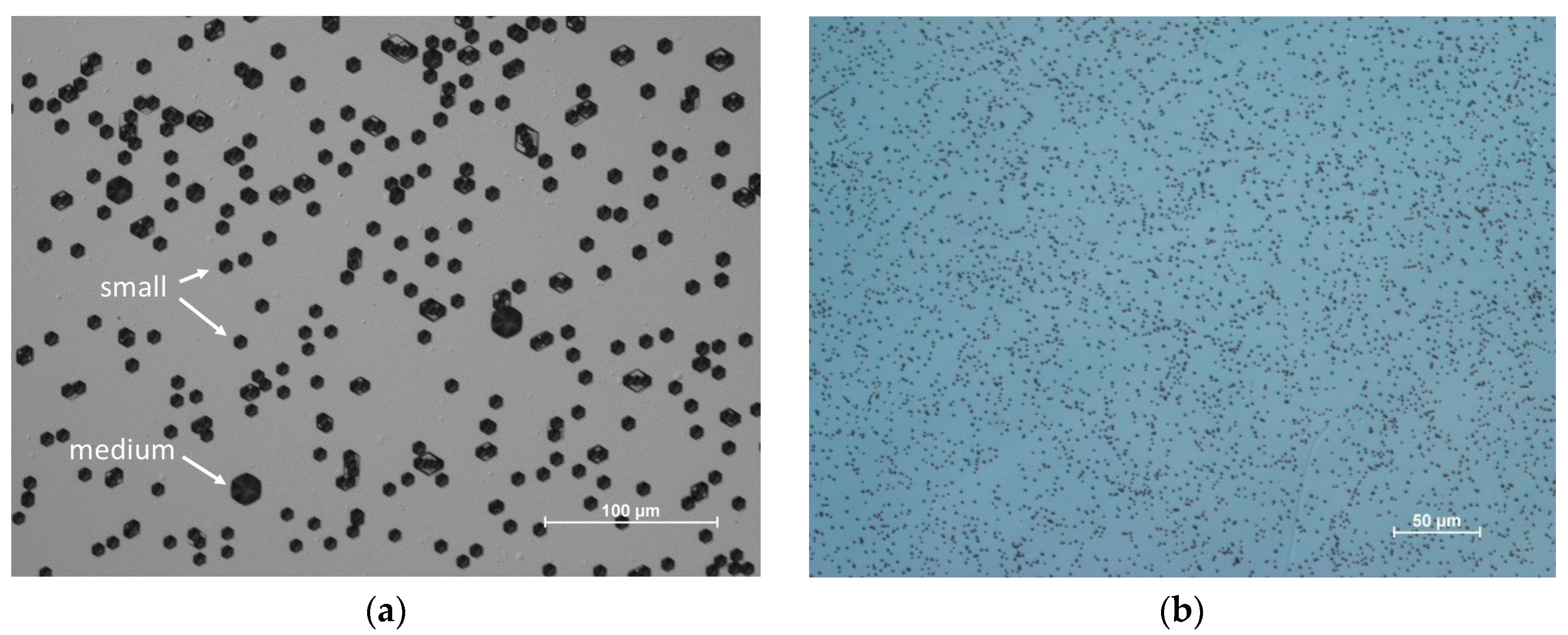
Figure 1. Optical microscope images of (0001) surface (after etching in KOH-NaOH solution at 500 °C) of commercially available 2-inch: (a) Am-GaN wafer; medium and small pits visible; EPD = 5 × 104 cm−2 (15 min etching); (b) HVPE-GaN; it is difficult to distinguish the size of pits; EPD = 5 × 106 cm−2 (5 min etching; longer time would result in overlapping of pits and lowering the EPD); attention should be paid to different scales on both pictures; difference in pit sizes between (a) and (b) results from different etching time.
Electronics 09 01342 g001
Figure 2. Scheme of GaN substrates with two kinds of (0001) crystallographic planes: (a) flat; (b) bent.
Electronics 09 01342 g002
Figure 3. Example of typical atomic force microscopy image of epi-ready (0001) surface of 2-inch ammonothermal GaN wafer fabricated at IHPP PAS: (a) 2 µm × 2 µm area and (b) 5 µm × 5 µm area.
Electronics 09 01342 g003
Figure 4. Scheme of horizontal HVPE reactor working at IHPP PAS. All reactants are transported by carrier gas.
Electronics 09 01342 g004
Figure 5. Scheme of: (a) high pressure ammonothermal autoclave; (b) temperature-time profiles of feedstock (red curve) and crystal growth zones (green curve) during a typical ammonothermal crystallization process at IHPP PAS.
Electronics 09 01342 g005
Figure 6. Examples of as-grown Am-GaN crystals of different shape: (a) ‘old’ hexagonal (b) ‘new’ round.
Electronics 09 01342 g006
Figure 7. (a) Am-GaN as-grown crystals from one crystal growth process; grid 1 mm; (b) 2-inch ammonothermal GaN substrate; primary flat (PF) and secondary flat (SF) are marked.
Electronics 09 01342 g007
Figure 8. HVPE-GaN grown on Am-GaN seed at IHPP PAS: (a) morphology; one central hillock is well visible; (b) X-ray rocking curve of Am-GaN seed and FS HVPE-GaN layer; full with half maximum (FWHM) for (00.2) reflection keeps the same value as Am-GaN seed: 43 arcsec and 50 arcsec, respectively.
Electronics 09 01342 g008
Figure 9. (a) Scheme of temperature distribution close to the growing crystal surface: it may allow for controlled crystal expansion and prevent crystallization on the sidewalls; (b) three-mm-thick HVPE-GaN grown on Ammono-GaN; equilibrium hexagonal crystal habit is well visible; c-plane is reduced; grid 1 mm.
Electronics 09 01342 g009
Table 1. Summarized advantages and disadvantages of HVPE and ammonothermal crystal growth methods.
HVPEAmmonothermal
Advantages
  • high purity
  • high growth rate
  • easy doping
  • reproducibility
  • few tens of crystals in one run
  • reproducibility
Disadvantages
  • requires high structural quality native seeds
  • side facets formation
  • one or a few crystals in one run
  • requires high structural quality native seeds
  • low growth rate
  • low purity