Compact Planar Super-Wideband Monopole Antenna with Four Notched Bands

 ,
,  ,
, 
Abstract
1. Introduction
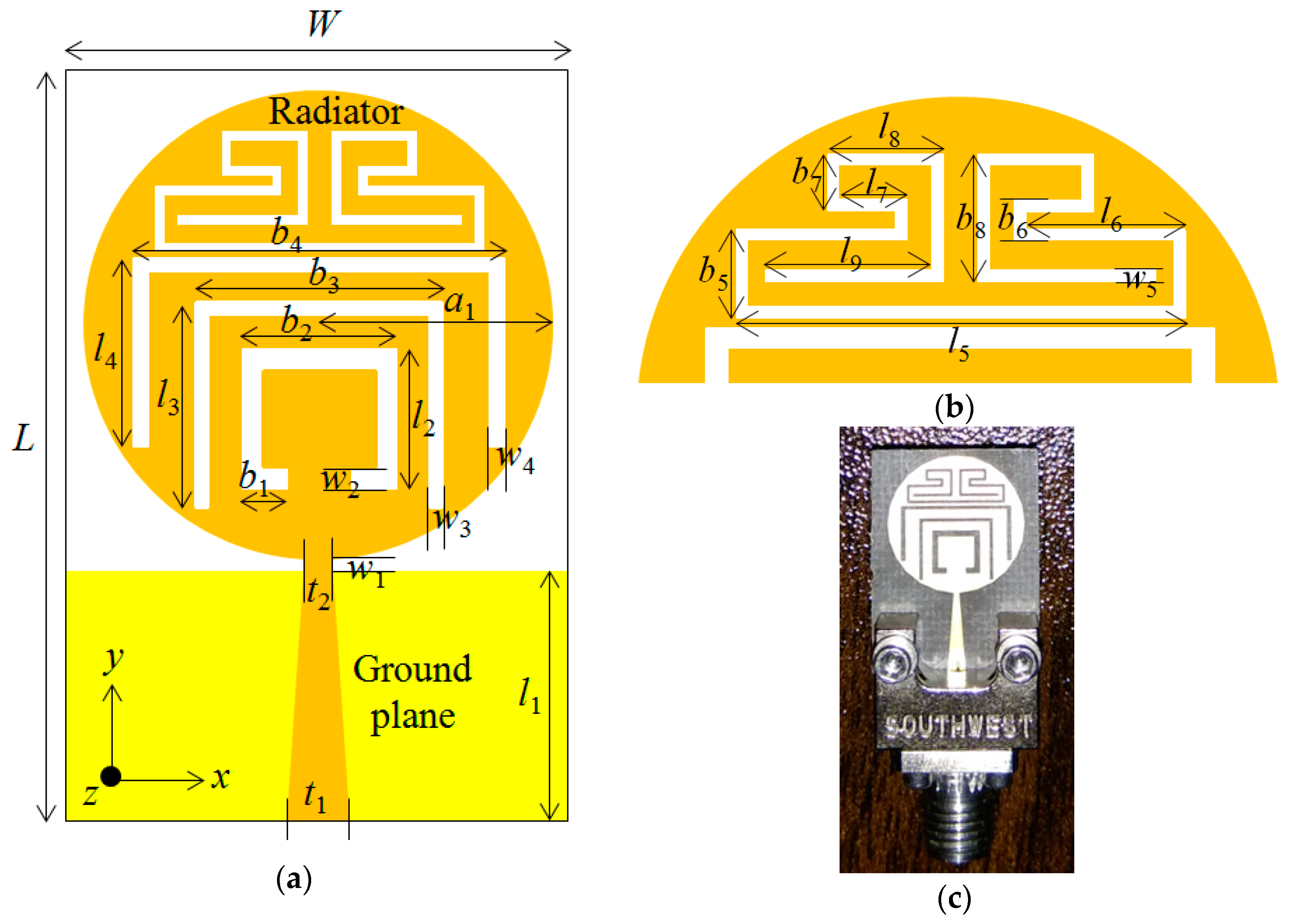
2. Antenna Design
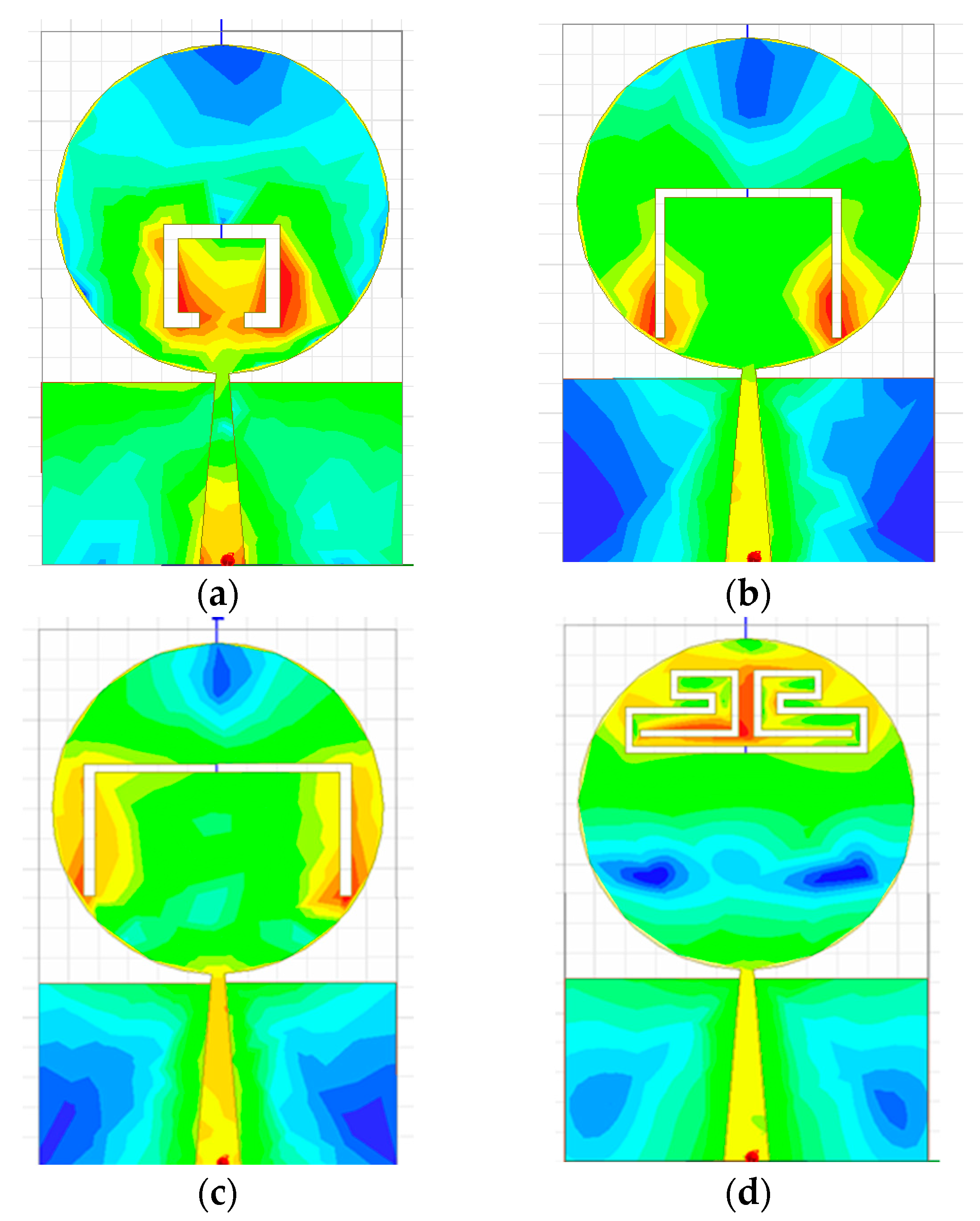
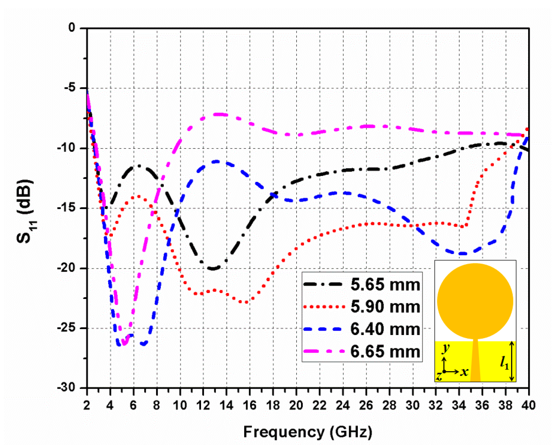
Parametric Studies of Antenna Performance
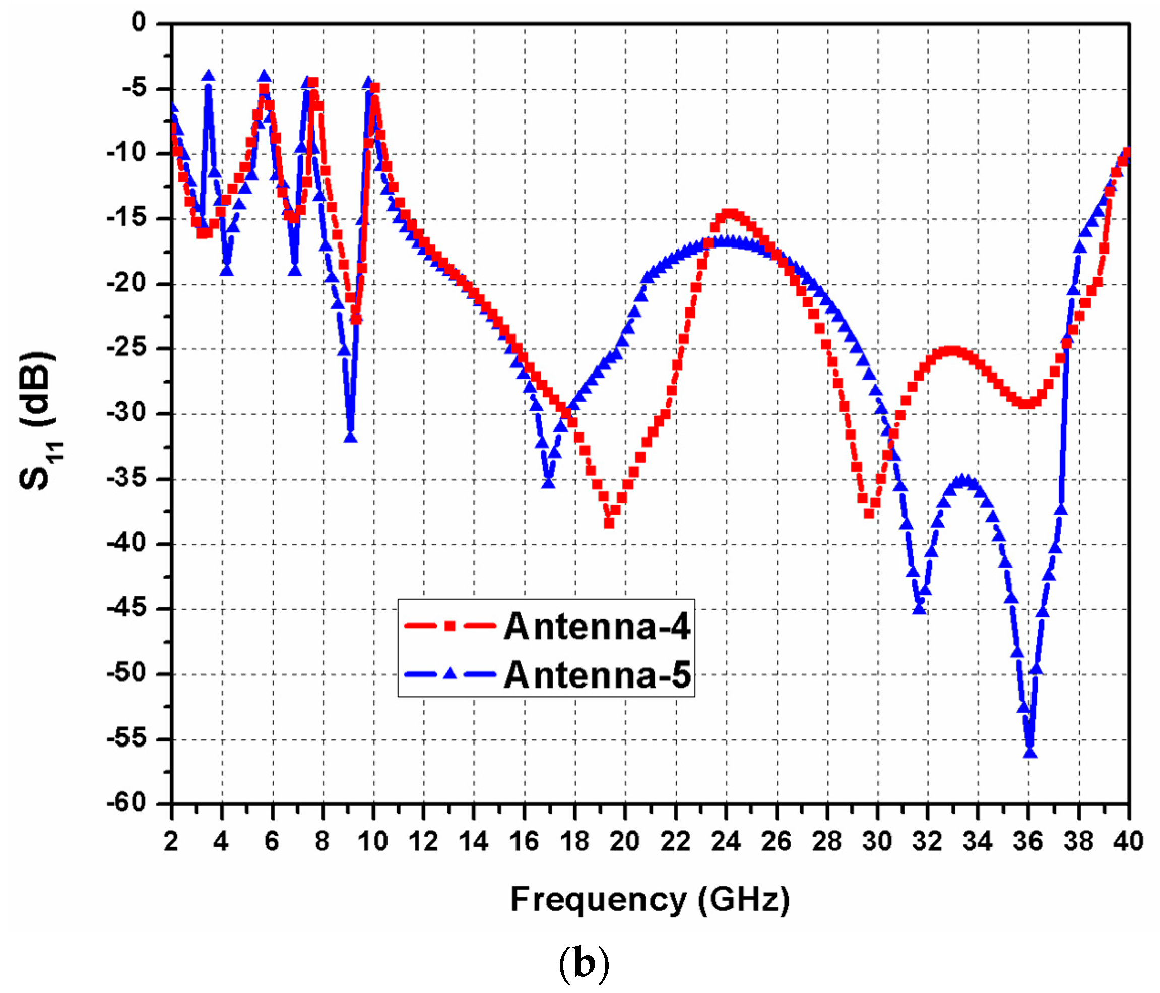
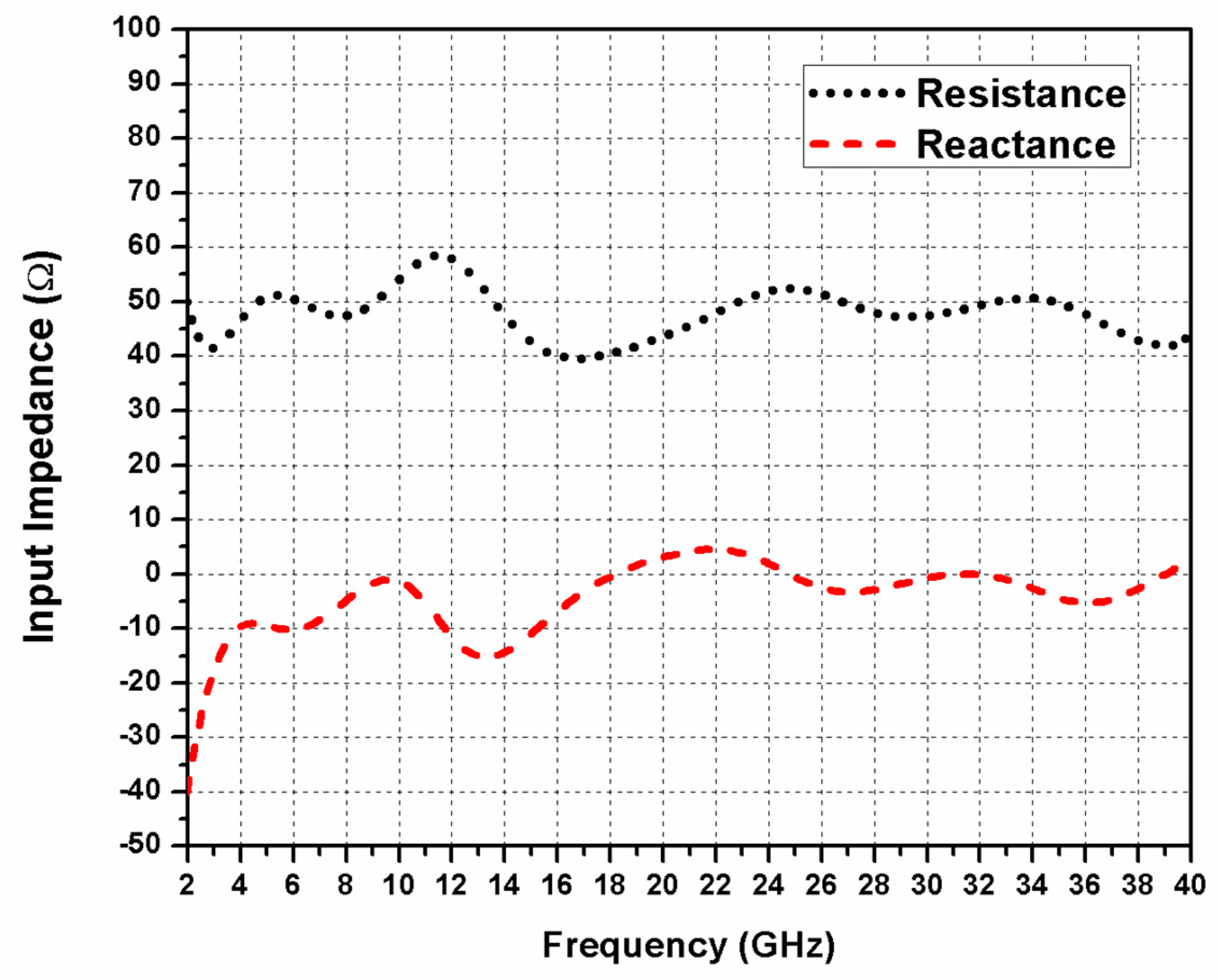
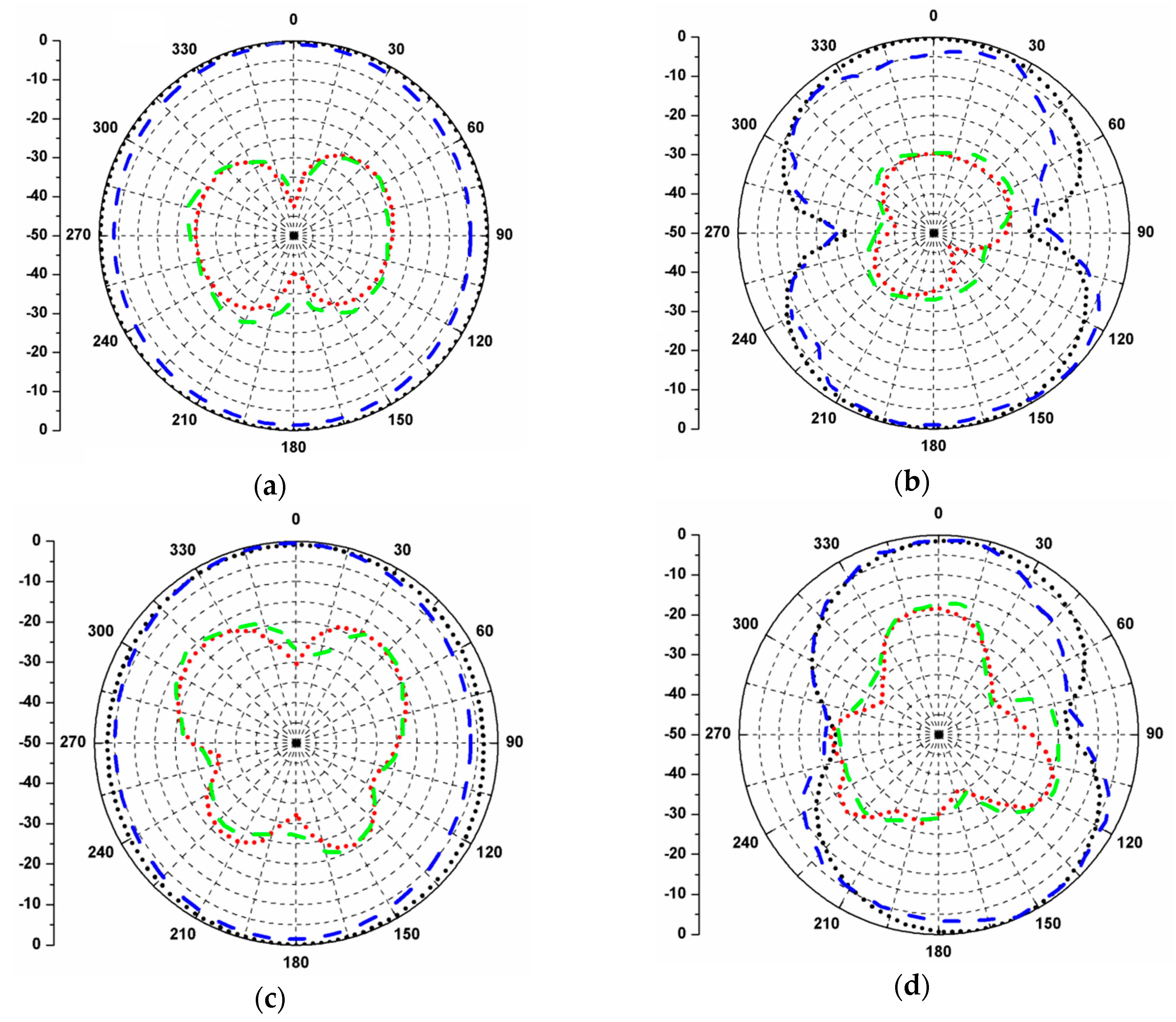
3. Results and Discussion
4. Conclusions
Author Contributions
Funding
Acknowledgments
Conflicts of Interest
References
- Moradhesari, A.; Moosazadeh, M.; Esmati, Z. Design of compact planar antenna with dual notched bands using slotted rectangular patch for ultrawideband applications. Microw. Opt. Technol. Lett. 2012, 54, 2053–2056. [Google Scholar] [CrossRef]
- Moosazadeh, M.; Esmati, Z. A small CPW-fed ultra wideband antenna with dual band-notched characteristics. Microw. Opt. Technol. Lett. 2012, 54, 1528–1532. [Google Scholar] [CrossRef]
- Federal Communications Commission. First Report and Order, Revision of Part 15 of the Commission’s Rules Regarding Ultrawideband Transmission Systems; Federal Communications Commission: Washington, DC, USA, 2002.
- Schantz, H.G. A brief history of UWB antennas. IEEE Aero. Electron. Syst. Mag. 2004, 19, 22–26. [Google Scholar] [CrossRef]
- Esmati, Z.; Moosazadeh, M. Dual band-notched small monopole antenna with bandwidth enhancement by means of defected ground structure (DGS) for UWB application. Appl. Comput. Electromagn. Soc. J. 2015, 30, 619–625. [Google Scholar]
- Balani, W.; Sarvagya, M.; Ali, T.; Anguera, J.; Andujar, A.; Das, S. Design techniques of super-wideband antenna–existing and future prospective. IEEE Access 2019, 7, 141241–141257. [Google Scholar] [CrossRef]
- Rahman, S.U.; Cao, Q.; Ullah, H.; Khalil, H. Compact design of trapezoid shape monopole antenna for SWB application. Microw. Opt. Technol. Lett. 2019, 61, 1931–1937. [Google Scholar] [CrossRef]
- Chen, K.R.; Row, J.S. A compact monopole antenna for super wideband applications. IEEE Antennas Wirel. Propag. Lett. 2011, 10, 488–491. [Google Scholar] [CrossRef]
- Okas, P.; Sharma, A.; Gangwar, R.K. Circular base loaded modified rectangular monopole radiator for super wideband application. Microw. Opt. Technol. Lett. 2017, 59, 2421–2428. [Google Scholar] [CrossRef]
- Rahman, M.N.; Islam, M.T.; Mahmud, M.Z.; Samsuzzaman, M. Compact microstrip patch antenna proclaiming super wideband characteristics. Microw. Opt. Technol. Lett. 2017, 59, 2563–2570. [Google Scholar] [CrossRef]
- Figueroa-Torres, C.Á.; Medina-Monroy, J.L.; Lobato-Morales, H.; Chávez-Pérez, R.A.; Calvillo-Téllez, A. A novel fractal antenna based on the Sierpinski structure for super wide-band applications. Microw. Opt. Technol. Lett. 2017, 59, 1148–1153. [Google Scholar] [CrossRef]
- Singhal, S.; Singh, A.K. Modified star-star fractal (MSSF) super-wideband antenna. Microw. Opt. Technol. Lett. 2017, 59, 624–630. [Google Scholar] [CrossRef]
- Okas, P.; Sharma, A.; Das, G.; Gangwar, R.K. Elliptical slot loaded partially segmented circular monopole antenna for super wideband application. AEU-Int. J. Electron. Commun. 2018, 88, 63–69. [Google Scholar] [CrossRef]
- Okas, P.; Sharma, A.; Gangwar, R.K. Super-wideband CPW fed modified square monopole antenna with stabilized radiation characteristics. Microw. Opt. Technol. Lett. 2018, 60, 568–575. [Google Scholar] [CrossRef]
- Ullah, S.; Ruan, C.; Sadiq, M.S.; Haq, T.U.; Fahad, A.K.; He, W. Super wide band, defected ground structure (DGS), and stepped meander line antenna for WLAN/ISM/WiMAX/UWB and other wireless communication applications. Sensors 2020, 20, 1735. [Google Scholar] [CrossRef]
- Aziz, S.Z.; Jamlos, M.F. Compact super wideband patch antenna design using diversities of reactive loaded technique. Microw. Opt. Technol. Lett. 2016, 58, 2811–2814. [Google Scholar] [CrossRef]
- Rao, Q.; Geyi, W. Compact multiband antenna for handheld devices. IEEE Trans. Antennas Propag. 2009, 57, 3337–3339. [Google Scholar]
- Chiani, M.; Giorgetti, A. Coexistence between UWB and narrow-band wireless communication systems. Proc. IEEE 2009, 97, 231–254. [Google Scholar] [CrossRef]
- Kumar, S.; Lee, G.H.; Kim, D.H.; Mohyuddin, W.; Choi, H.C.; Kim, K.W. Multiple-input-multiple-output/diversity antenna with dual band-notched characteristics for ultra-wideband applications. Microw. Opt. Technol. Lett. 2020, 62, 336–345. [Google Scholar] [CrossRef]
- Shahsavari, H.; Nourinia, J.; Shirzad, H.; Shokri, M.; Asiaban, S.; Amiri, Z.h.; Virdee, B. Compact planar super-wideband antenna with band-notched function. Appl. Comput. Electromagn. Soc. J. 2013, 28, 608–613. [Google Scholar]
- Oskouei, H.D.; Mirtaheri, A. A monopole super wideband microstrip antenna with band-notch rejection. In Progress in Electromagnetics Research Symposium—Fall (PIERS—FALL); IEEE: Singapore, 2017; pp. 2019–2024. [Google Scholar]
- Abbas, A.S.; Abdelazeez, M.K. A dual band notch planar SWB antenna with two vertical sleeves on slotted ground plane. In Proceedings of the IEEE International Symposium on Antennas and Propagation (APSURSI), Fajardo, Puerto Rico, 26 June–1 July 2016. [Google Scholar]
- Manohar, M.; Kshetrimayum, R.S.; Gogoi, A.K. A compact dual band-notched circular ring printed monopole antenna for super-wideband applications. Radioengineering 2017, 26, 64–70. [Google Scholar] [CrossRef]
- Liu, J.; Esselle, K.P.; Hay, S.G.; Zhong, S.S. Study of an extremely wideband monopole antenna with triple band-notched characteristics. Prog. Electromagn. Res. 2012, 123, 143–158. [Google Scholar] [CrossRef]
- Zhang, X.; Ur Rahman, S.; Cao, Q.; Gil, I.; Khan, M.I. A novel SWB antenna with triple band-notches based on elliptical slot and rectangular split ring resonators. Electronics 2019, 8, 202. [Google Scholar] [CrossRef]
- Singh, S.; Varma, R.; Sharma, M.; Hussain, S. Superwideband monopole reconfigurable antenna with triple notched band characteristics for numerous applications in wireless system. Wireless Pers. Commun. 2019, 106, 987–999. [Google Scholar] [CrossRef]
- Pozar, D.M. Microwave Engineering; Addison Wesley: Boston, MA, USA, 1990. [Google Scholar]
- Sarkar, D.; Srivastava, K.V.; Saurav, K. A compact microstrip-fed triple band-notched UWB monopole antenna. IEEE Antennas Wirel. Propag. Lett. 2014, 13, 396–399. [Google Scholar] [CrossRef]
- Gurel, C.S.; Yazgan, E. Resonant frequency of an air gap tuned circular disc microstrip antenna. Int. J. Electron. 2000, 87, 973–979. [Google Scholar] [CrossRef]
- Abdelhalim, C.; Farid, D. A compact planar UWB antenna with triple controllable band-notched characteristics. Int. J. Antennas Propag. 2014, 848062. [Google Scholar] [CrossRef]


| Parameter | Dimension (mm) | Parameter | Dimension (mm) |
|---|---|---|---|
| L | 18 | b3 | 6 |
| W | 12 | b4 | 9 |
| a | 5.55 | b5 | 1.55 |
| l1 | 6.15 | b6 | 0.75 |
| l2 | 3.5 | b7 | 1 |
| l3 | 5 | b8 | 2.25 |
| l4 | 4.45 | w1 | 0.3 |
| l5 | 8 | w2 | 0.5 |
| l6 | 2.75 | w3 | 0.3 |
| l7 | 1.25 | w4 | 0.4 |
| l8 | 2.25 | w5 | 0.25 |
| l9 | 3 | t1 | 1.5 |
| b1 | 1.2 | t2 | 0.4 |
| b2 | 3.9 | h | 0.5 |
| Ref. | Antenna Size (mm × mm × mm) | Resonating Band (GHz) | Impedance Bandwidth (GHz) | Bandwidth Ratio | Number of Notch Bands | Notch Band Center Frequency (GHz) | Peak Gain (dB) |
|---|---|---|---|---|---|---|---|
| [9] | 52 × 42 × 1.575 | 0.96–13.98 | 13.02 | 14.6:1 | - | - | 5.5 |
| [10] | 32 × 22 × 1.6 | 2.5–29 | 26.5 | 11.6 | - | - | 6 |
| [11] | 62 × 64 × 1.58 | 1.68–26 | 24.32 | 15.5:1 | - | - | 5 |
| [12] | 19.7 × 19 × 1.6 | 4.6–52 | 47.4 | 11.3:1 | - | - | 14 |
| [13] | 52.25 × 42 × 1.575 | 0.99–10.9 | 9.91 | 11:1 | - | - | 4.5 |
| [14] | 52 × 46 × 1.6 | 0.95–13.8 | 12.85 | 14.5:1 | - | - | 6 |
| [15] | 35 × 35 × 1.57 | 3.08–40.9 | 37.82 | 13.3:1 | - | - | 5.9 |
| [16] | 25 × 26 × 1.6 | 2.43–32.93 | 30.5 | 13.5:1 | - | - | 7.35 |
| [20] | 30 × 30 × 1.6 | 2.39–40 | 37.61 | 16.7:1 | 1 | 5.5 | 3.5 |
| [21] | 30 × 30 × 1.6 | 3–50 | 47 | 16.7:1 | 1 | 5.5 | 10 |
| [22] | 35 × 30 × 1.6 | 3.2–40 | 36.8 | 12.5:1 | 2 | 5.5, 7.5 | 6.5 |
| [23] | 30 × 24 × 0.787 | 1.6–25 | 23.4 | 15.6:1 | 2 | 3.5, 7.5 | 6 |
| [24] | 150 × 150 × 0.787 | 0.72–25 | 24.28 | 34:1 | 3 | 2.4, 5.5, 7.5 | 7 |
| [25] | 57 × 34 × 1 | 1.42–50 | 48.58 | 35.2:1 | 3 | 3.4, 5.6, 9 | 6.5 |
| [26] | 27 × 32 × 0.787 | 3.36–39.61 | 36.25 | 11.8:1 | 3 | 3.75, 5.48, 7.38 | 6.89 |
| Prop. | 18 × 12 × 0.5 | 2.5–40 | 37.5 | 16:1 | 4 | 3.5, 5.5, 7.5, 10.5 | 5.8 |
© 2020 by the authors. Licensee MDPI, Basel, Switzerland. This article is an open access article distributed under the terms and conditions of the Creative Commons Attribution (CC BY) license (http://creativecommons.org/licenses/by/4.0/).
Share and Cite
Kumar, S.; Lee, G.H.; Kim, D.H.; Haunan, N.S.; Choi, H.C.; Kim, K.W. Compact Planar Super-Wideband Monopole Antenna with Four Notched Bands. Electronics 2020, 9, 1204. https://doi.org/10.3390/electronics9081204
Kumar S, Lee GH, Kim DH, Haunan NS, Choi HC, Kim KW. Compact Planar Super-Wideband Monopole Antenna with Four Notched Bands. Electronics. 2020; 9(8):1204. https://doi.org/10.3390/electronics9081204
Chicago/Turabian StyleKumar, Sachin, Gwan Hui Lee, Dong Hwi Kim, Nashuha Syifa Haunan, Hyun Chul Choi, and Kang Wook Kim. 2020. "Compact Planar Super-Wideband Monopole Antenna with Four Notched Bands" Electronics 9, no. 8: 1204. https://doi.org/10.3390/electronics9081204
APA StyleKumar, S., Lee, G. H., Kim, D. H., Haunan, N. S., Choi, H. C., & Kim, K. W. (2020). Compact Planar Super-Wideband Monopole Antenna with Four Notched Bands. Electronics, 9(8), 1204. https://doi.org/10.3390/electronics9081204