Article

A Fuzzy Logic-Based Control Algorithm for the Recharge/V2G of a Nine-Phase Integrated On-Board Battery Charger

Department of Industrial Engineering, University of Salerno, 84084 Fisciano, Italy
*
Author to whom correspondence should be addressed.
Electronics 2020, 9(6), 946; https://doi.org/10.3390/electronics9060946
Submission received: 28 April 2020 / Revised: 27 May 2020 / Accepted: 1 June 2020 / Published: 7 June 2020
(This article belongs to the Special Issue Prospects for Integrating Electric Vehicles into Power Systems)

Abstract

:
Energy demand associated with the ever-increasing penetration of electric vehicles on worldwide roads is set to rise exponentially in the coming years. The fact that more and more vehicles will be connected to the electricity network will offer greater advantages to the network operators, as the presence of an on-board battery of discrete capacity will be able to support a whole series of ancillary services or smart energy management. To allow this, the vehicle must be equipped with a bidirectional full power charger, which will allow not only recharging but also the supply of energy to the network, playing an active role as a distributed energy resource. To manage recharge and vehicle-to-grid (V2G) operations, the charger has to be more complex and has to require a fast and effective control structure. In this work, we present a control strategy for an integrated on-board battery charger with a nine-phase electric machine. The control scheme integrates a fuzzy logic controller within a voltage-oriented control strategy. The control has been implemented and simulated in Simulink. The results show how the voltage on the DC-bus is controlled to the reference value by the fuzzy controller and how the CC/CV charging mode of the battery is possible, using different charging/discharging current levels. This allows both three-phase fast charge and V2G operations with fast control response time, without causing relevant distortion grid-side (Total Harmonic Distortion is maintained around 3%), even in the presence of imbalances of the machine, and with very low ripple stress on the battery current/voltage.

1. Introduction

The advent of smart grids and the ever greater and more frequent integration of distributed energy sources (DER) into modern energy systems is causing huge changes in the concept of ancillary services for transmission and distribution systems. The operators are called to new and stimulating challenges to maintain the high quality of their services, keeping up with the new modern technologies. One of these challenges is the integration and use of batteries to provide ancillary services in power systems. Two possibilities can be considered for battery integration, and one does not exclude the other: it is possible to use both stationary storage systems and batteries integrated into electric vehicles (EVs); the former have the great advantage of being permanently available, thus guaranteeing a reliable service, but the disadvantage of having a high initial cost. EVs batteries have traction as their primary purpose; however, when not in use (e.g., during a stop), they can provide the ancillary services requested with remuneration for the vehicle owners. Here, we focus on the use of storage systems integrated into EVs.
To allow the connection of the battery to the grid, the EV must be equipped with a bidirectional battery charger. In this case, two working modes are possible: the conventional grid-to-vehicle mode (G2V), that allows the recharge of the battery for traction mode; and the vehicle-to-grid mode (V2G) for supplying energy to the grid. Particularly, several studies [1,2,3] have illustrated how the V2G mode allows the provision of ancillary services to both the transmission (frequency regulation, spinning reserve, black start provision) and distribution networks (voltage drop [4], load shifting [5], peak shaving [6], valley filling [7]). These services can also be provided in a differentiated way based on the features of the EV parking areas [8]. EVs can also be combined with renewable energy sources (RES) to facilitate their integration to the grid, to remedy their intermittent availability and to level the demand curve [9] (Figure 1) by promoting the development of techniques and methods to improve energy efficiency, quality of the voltage supply and saving costs [10].
EVs chargers can be classified in on-board and off-board [11]. The main difference is the power that can be transferred to the battery: usually, the power range of an on-board charger is between 3.6 and 43 kW; if more power has to be transferred to the vehicle, an off-board charger is used due to weight, cost and encumbrance problems. An alternative solution is to use the powertrain components (motor and converters) during both traction and charging/V2G mode: in this way, the powertrain will act as an integrated on-board battery charger (OBC).
Particularly, several works can be found in the literature which showed the application of integrated chargers on powertrains mounting a three-phase machine [12,13,14,15]. Due to the consolidated technology, the three-phase configuration is the most used one in modern EVs [16], even though a solution that is slowly emerging can be found in multiphase machines. In fact, in the literature, several research papers have covered the modeling, strategies for drive control, power converter modulation, and fault-tolerant operations [17,18,19]. In particular, the advantages given by fault tolerance strategies and current splitting on more phases will help considering multiphase topologies as a possible solution in future EVs.
Also, multiphase machines can be used as an integrated OBC to achieve EV charging/V2G operations. Specifically, the inverter used in traction mode has to be controlled as a PWM rectifier during recharging mode. In the literature, PWM rectifier control strategies can be classified as voltage-based and virtual flux-based [20]; particularly, here, we will consider the voltage-oriented control (VOC) strategy. Several examples of VOC application on different multiphase machine topologies (five, six and nine-phases) can be found in the literature: in [21], a wide overview was reported, in which authors showed how VOC, combined with additional degrees of freedom given by multiphase systems, can be conveniently utilized to achieve zero torque production of the machine during charging operation; in [22], a VOC strategy was applied on a six-phase integrated OBC: the configuration achieved zero torque production by the machine during charging/ V2G operations using a reduced number of both on-board (EV) and off-board (charging station) components; in [23], Bodo et al. (2017) presented a novel VOC control algorithm for charging/V2G operations of a nine-phase OBC based on a balancing current controller (BCC) and a main current controller (MCC); in particular, on-board battery recharge was achieved using the MCC by controlling the zero-sequence d-axis current component to the desired value and the zero-sequence q-axis component to zero; the BCC was used to mitigate the unbalances caused by non-perfect symmetry of the machine parameters in the real case; in [24], a VOC control strategy for charging mode of a nine-phase based propulsion system, including current balancing and interleaving strategy, was described.
The aim of this work, which takes up and completes the considerations illustrated in [25], is to present a VOC control algorithm for a nine-phase machine with three isolated neutral points connected to a nine-phase inverter during both charging and V2G mode. In previous works, this technique used a very large number of PI regulators, making the system very complex in computing constants. Here, we present a simplified control strategy based on the implementation of a fuzzy logic regulator and an adaptive hysteresis band controller (AHBC), combining the simplicity of a hysteretic control with the advantage of an adaptive bandwidth that allows maintaining the switching frequency at an almost constant value. Power flow for charging/V2G of the on-board battery is ensured by connecting the three-phase supply to the three neutral points of the machine and controlling the considered inverter as PWM boost rectifier to achieve grid side unity power factor recharge/V2G operations, with no torque production by the motor and with low distortion to the grid current. The proposed control scheme can be adapted to different power charging levels, also showing effectiveness against imbalances due to the inequality of the machine phase parameters.

2. System Description

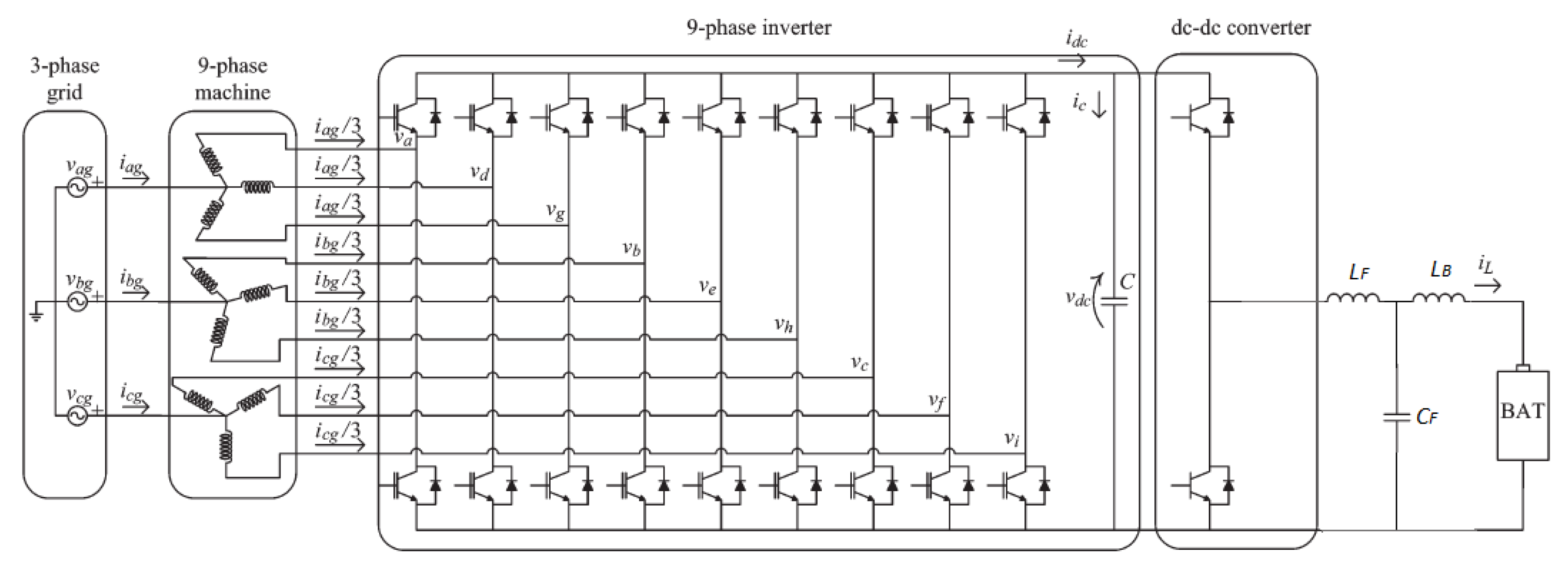
The considered integrated charger/propulsion system has already been presented in [26] and is shown in Figure 2. Without a connection to the electrical grid, it represents a possible propulsion system for an EV: it is composed of Li-Ion battery, an LCL filter, a DC-DC converter, a nine-phase inverter connected to the DC-link capacitor and a nine-phase AC machine.
In three-phase fast charging/V2G mode operations, this particular nine-phase machine configuration (with three isolated neutral points) is particularly suitable for integrated recharge, because grid connections can be attached directly to the neutral points of the machine (if accessible) without any hardware reconfiguration and with no average torque production. The latter was demonstrated in [27] and was reported in the following case of a symmetrical machine: if the space vector of the current into the torque producing plane αβ is considered:
i α β = 2 / 9   ( i a + ā i b + ā 2 i c + ā 3 i d + ā 4 i e + ā 5 i f + ā 6 i g + ā 7 i h + ā 8 i i )
where ā = e i γ = cos γ + i sin γ and γ = 2 π / 9 for a symmetrical machine. Since the individual windings in any of the three-phase set connected to the same neutral point are displaced by 120° along the stator periphery, and if the individual phase parameters of the machine are supposed to be equal, then the same current flows through each of them:
i a = i d = i g = i a g 3 i b = i e = i h = i b g 3 i c = i f = i i = i c g 3
Substituting Equation (2) in Equation (1), we obtain that the rotational component is zero, leading to no torque production. Moreover, the zero-sequence component of the current, in this case, represents the sum of the currents flowing through the same neutral point attached three-phase winding of the machine or, equally, the grid currents and are used for battery charging. Thus, in charging/V2G mode, the sets of the three three-phase windings behave as simple resistance-inductance passive components. As also shown in [27], the winding configuration is irrelevant for charging purposes, since the same considerations can be applied to both symmetrical and asymmetrical machines.
Ultimately, this system can be represented with an equivalent three-phase scheme, in which the impedances presented to the grid current flow are composed by the stator leakage inductances and the stator resistances, and are used for filtering so that the inverter used in the traction mode acts as a PWM boost-rectifier during charging/V2G mode.

3. Proposed Control System

The proposed control acts on two main parts of the system: the nine-phase inverter, which is controlled as a PWM boost rectifier, and the DC-DC converter. On the inverter-side, the control strategy aims to boost the DC-Link voltage to the target value using VOC. On the DC-DC converter side, the control aims to follow the Constant-Current/Constant Voltage (CC-CV) recharge profile for a Li-Ion battery during charging mode and to discharge the battery in V2G mode.

3.1. Nine-Phase PWM Rectifier Control Strategy

To control the nine-phase rectifier, a voltage-oriented control strategy has been implemented (Figure 3). In particular, the VOC control scheme allows having a high dynamic and static performance using an internal current control loop, in which its reference is given by an outer voltage control loop, allowing the control of the DC-link voltage at the desired value V D C by a fuzzy logic controller. Several works can be found in the literature, covering a fuzzy control strategy for a PWM rectifier [28,29]. In this proposed fuzzy controller, the inputs are the voltage error and the error variation, defined respectively as:
Δ v D C = V D C V D C δ ( Δ v D C ) = Δ v D C ( h ) Δ v D C ( h 1 )
Controller’s output is the discrete d-axis current variation ΔId(h), expressed in Park domain, which is iteratively added to the former h − 1 value of the d-axis current, so that the reference for the d-axis current is progressively increased or decreased:
I d ( h ) = I d ( h 1 ) + Δ I d ( h )
where the subscript “h” represents the value sampled at the instant hTs, and Ts is the sampling period. Also, the q-axis component reference is set to zero. For each current set, an inverse Park transformation is then employed to obtain the abc current components. A phase-locked loop (PLL) is used to identify the phase angle of the voltage grid, first phase Vag. This information is then given in input to the Park transformation block to ensure charging at unity power factor.
Zero torque production by the machine during the charging/V2G mode is achieved by simultaneous identical switch control of all inverter legs belonging to the same set (neutral point). To obtain simultaneous switch control, phase currents belonging to the same set have the same reference and its phase shift varies according to the considered set, to ensure the hypothesis of symmetry: 0° for the first phase, 120° for the second one, and 240° for the third one.
References for phase currents are the inputs to an adaptive hysteresis band controller, which uses a variable bandwidth. In this way, it is possible to combine the simplicity and good dynamics of the hysteretic control, keeping an almost constant switching frequency. As in [30], half-bandwidth (HB) value can be defined as:
H B = V D C 8 L f { 1 4 L 2 V D C 2 [ v s ( t ) L m ] 2 }
where m is the slope of the reference current wave, VDC is the voltage on the DC link, L is the machine leakage inductance, and f is the switching frequency. If the frequency is set, the AHBC provides the gate signals by varying the HB according to the remaining system parameters, to keep the switching frequency constant to the set value.
Also, it is worth emphasizing the mitigation effects of this method on the unbalances which are inevitably present in the real model; in fact, in the proposed model, we have ideally assumed the equality of the phase parameters of the nine-phase machine. However, in the real case, some asymmetries may occur, leading to imbalances between phase currents of the same set. This problem can be attenuated by varying the HB associated to each phase by putting in (5) the measured value of the phase leakage inductance.

3.2. DC-DC Converter Control Strategy

The control scheme for the DC-DC converter generally varies depending on the battery technology and the state of charge (SOC). Particularly, the most commonly used for EV applications are the Li-Ion batteries, in which the control system manages the double operating mode CC-CV during the charging phase, and also manages V2G operation. As in [31] and shown in Figure 4, there are three possible operation modes:
  • in CV recharging mode, there is an outer control loop that controls the battery voltage to the reference value. It delivers a reference for the battery charging current flowing in the inductance ILF. The difference between ILF and the measured battery current is given in input to the inner current control loop that outputs the duty cycle for the DC-DC converter. This duty cycle (feedback term) is only a part of the total duty cycle: in fact, it is added to a feed-forward term which is able to considerably improve the start-up behavior of the converter.
  • in CC charging mode, the control scheme consists of only the inner current loop that controls the current ILF to the reference value.
  • in V2G mode, the control scheme consists of only the inner current loop that discharges the battery following the reference value.

4. Discussion of Considered Case Study

4.1. Simulation Parameters

The described model and the control system were implemented and simulated using MATLAB/Simulink. Simulation parameters are described in Table 1. As seen in Figure 2, the power system is composed of an AC induction machine, modeled with its leakage resistance and inductance; a nine phase inverter/PWM rectifier, composed of IGBT with antiparallel diode and a switching frequency of fs = 20 kHz, a DC-link capacitor, a DC-DC converter composed of IGBT and diode in antiparallel, an LCL filter, and a Li-Ion battery.
Regarding the battery, the Simulink model described in [32] was considered. The simulated battery pack consists of 37 cells in series with a maximum voltage of Vmax = 155 V and capacity of Cbatt = 27 Ah. The fuzzy logic controller is composed of two inputs with five membership functions, and one output composed of five membership functions, as shown in Figure 5. Table 2 shows the inference table; de-fuzzification is accomplished with the centroid method.

4.2. Simulation Results

4.2.1. Charging Mode

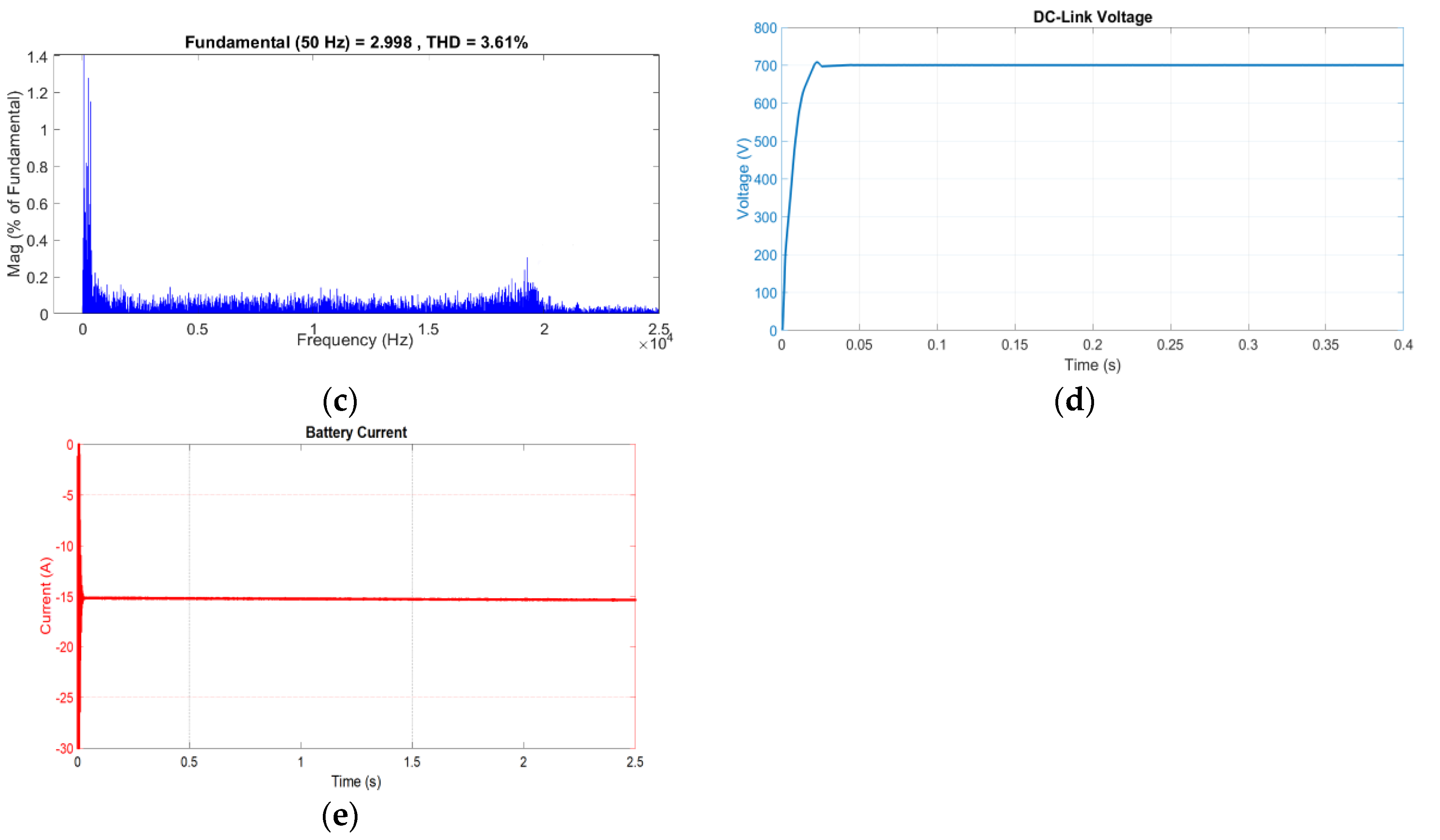
Simulation results for charging in CC-CV mode are reported in Figure 6. In particular, Figure 6a depicts the grid side voltage, the grid side current, and the machine phase current; Figure 6b shows the grid current fast Fourier transform (FFT) in the frequency range [0–1000] Hz; and Figure 6c shows the grid current FFT in the frequency range [0–2.5] kHz.
As shown by the results, charging takes place at unity power factor as grid side voltage, grid side current and machine phase current are in phase with each other. As expected, machine current is one-third of the grid side current. These considerations can be repeated equally for the other two phases, with a phase shift of 120° and 240°, respectively. FFT shows a low current ripple (THD of 3.7%), and only a high-frequency component at the switching frequency of 20 kHz.
On the DC side of the system, the fuzzy logic controller allows controlling the DC-link voltage to the reference value of VDC* = 700 V with low overshoot and ripple (Figure 6d). Regarding the CV charging mode, the battery voltage is controlled to the reference value of Vbatt* = 155 V (Figure 6e); in CC charging mode the battery charging current is controlled to the reference value of ILF* = 12 A. As shown, battery parameters have an almost constant trend, with no ripple stress on the pack.

4.2.2. Discharging V2G Mode

Simulation results for V2G mode are reported in Figure 7. The same consideration for charging mode can be applied in this case. It is worth noticing that grid-side currents and voltage are now in phase opposition with each other; also, on the battery side, the reference current for the discharge is, in this case, negative (ILF* = −15 A), hence the battery is now discharging towards the grid.

4.2.3. Transition between Different Charging/Discharging Levels

The transition behavior of the proposed control system is shown in Figure 8. In particular, three charging levels in CC charging mode have been considered (ILF* = [30, 20, 5] A at Time t = [0, 0.15, 0.30] s) and one discharging V2G level (ILF* = −20 A at t = 0.45 s). Furthermore, the variation of the grid current’s THD according to the controlled charge/discharge current is shown in Table 3. The results show how the current is controlled to the reference value, while the DC-link voltage approaches the reference value as the reference current lowers its value; response time to the variation is very low (order of magnitude of hundreds of milliseconds maximum); THD value remains around 3% as the reference current varies.

4.2.4. Imbalances Mitigation Effects of the AHBC

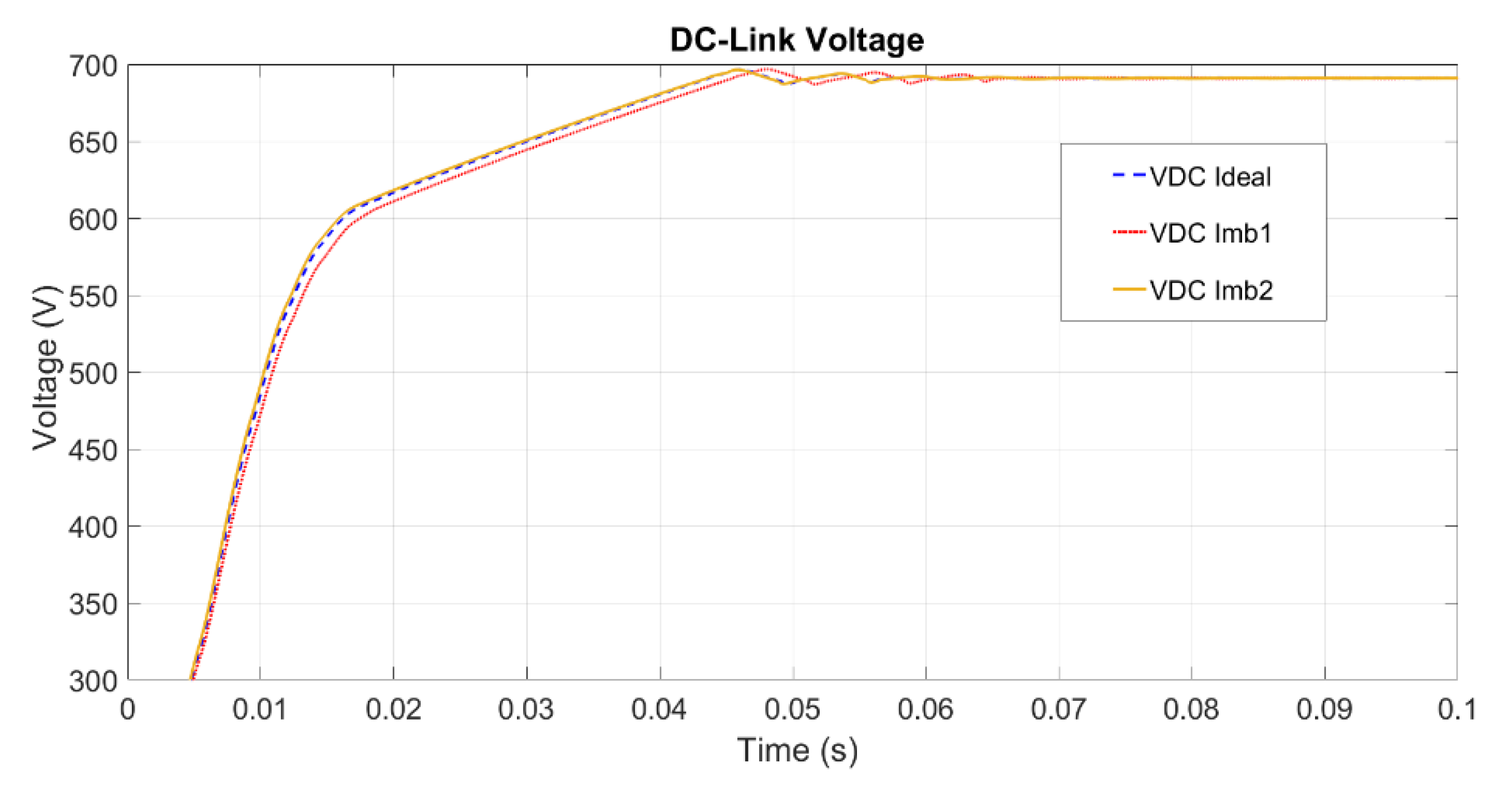
Mitigation effects of the AHBC on the nine-phase inverter DC-link voltage control, due to imbalances between machine phase parameters, are shown in Figure 9. In particular, three cases have been examined, the phase parameters of which are shown in Table 4. The simulation results show how, in the three considered cases, voltage trend deviation is minimal and tends to accentuate when there is no repetitiveness of the phase parameters of each set (Imb1 case).

5. Conclusions

In this paper, a control algorithm for an integrated OBC composed of a nine-phase machine, with three isolated neutral points connected to a nine-phase inverter during charging/V2G mode has been described. The advantages and applications of powertrains composed of multiphase machines and, particularly, of this topology have been examined. The described control scheme integrated VOC strategy with a fuzzy logic controller.
The simulation results show how voltages and currents on either grid side and battery side are controlled to the reference value, without causing any particular stress to both the power supply (in terms of THD) and the battery (in terms of ripple stress on the pack). This allows a recharge that is faster as high as the current is bearable by the power electronics of the system. Also, they show short response time to changes in the current reference value, keeping the same degree of performance, even in the presence of imbalances on the machine phase parameters.

Author Contributions

Conceptualization, V.C.; Methodology, F.D.L.; Software, F.D.L.; Supervision, V.C. and V.G.; Writing–original draft, F.D.L.; Writing–review & editing, V.C. and V.G. All authors have read and agreed to the published version of the manuscript.

Conflicts of Interest

The authors declare no conflict of interest.

References

  1. Arias, N.B.; Hashemi, S.; Andersen, P.B.; Traholt, C.; Romero, R. Distribution System Services Provided by Electric Vehicles: Recent Status, Challenges, and Future Prospects. IEEE Trans. Intell. Transp. Syst. 2019, 20, 4277–4296. [Google Scholar] [CrossRef] [Green Version]
  2. Yilmaz, M.; Krein, P.T. Review of Benefits and Challenges of Vehicle-to-Grid Technology. In Proceedings of the 2012 IEEE Energy Conversion Congress and Exposition, Raleigh, NC, USA, 15–20 September 2012; pp. 3082–3089. [Google Scholar]
  3. Ehsani, M.; Falahi, M.; Lotfifard, S. Vehicle to Grid Services: Potential and Applications. Energies 2012, 5, 4076–4090. [Google Scholar] [CrossRef] [Green Version]
  4. Kati, V.A.; Stanisavljevi, A.M.; Dumni, B.P.; Popadi, B.P. Impact of V2G operation of electric vehicle chargers on distribution grid during voltage dips. In Proceedings of the 2019-18th International Conference on Smart Technologies, Novi Sad, Serbia, 1–4 July 2019; pp. 1–6. [Google Scholar]
  5. Aziz, M.; Oda, T.; Mitani, T.; Watanabe, Y.; Kashiwagi, T. Utilization of Electric Vehicles and Their Used Batteries for Peak-Load Shifting. Energies 2015, 8, 3720–3738. [Google Scholar] [CrossRef] [Green Version]
  6. Calderaro, V.; Galdi, V.; Graber, G.; Graditi, G.; Lamberti, F. Impact Assessment of Energy Storage and Electric Vehicles on Smart Grids. In Proceedings of the IEEE Electric Power Quality and Supply Reliability Conference, Rakvere, Estonia, 11–13 June 2014; pp. 15–18. [Google Scholar]
  7. Muñoz, E.R.; Razeghi, G.; Zhang, L.; Jabbari, F. Electric Vehicle Charging Algorithms for Coordination of the Grid and Distribution Transformer Levels. Energy 2016, 113, 930–942. [Google Scholar] [CrossRef]
  8. Graber, G.; Lamberti, F.; Calderaro, V.; Galdi, V.; Piccolo, A. Stochastic Characterization of V2G Parking Areas for the Provision of Ancillary Services. In Proceedings of the 2017 IEEE PES Innovative Smart Grid Technologies Conference Europe, Torino, Italy, 26–29 September 2017. [Google Scholar]
  9. Salvatti, G.A.; Carati, E.G.; da Costa, J.P.; Cardoso, R.; Stein, C.M.O. Integration of electric vehicles in smart grids for optimization and support to distributed generation. In Proceedings of the 2018 13th IEEE International Conference on Industry Applications, São Paulo, Brazil, 11–14 November 2018; pp. 963–970. [Google Scholar]
  10. Amamra, S.; Marco, J. Vehicle-to-Grid Aggregator to Support Power Grid and Reduce Electric Vehicle Charging Cost. IEEE Access 2019, 7, 178528–178538. [Google Scholar] [CrossRef]
  11. Yilmaz, M.; Krein, P.T. Review of Battery Charger Topologies, Charging Power Levels, and Infrastructure for Plug-In Electric and Hybrid Vehicles. IEEE Trans. Power Electron. 2013, 28, 2151–2169. [Google Scholar] [CrossRef]
  12. Haghbin, S.; Lundmark, S.; Alaküla, M.; Carlson, O. Grid-Connected Integrated Battery Chargers in Vehicle Applications: Review and New Solution. IEEE Trans. Ind. Electron. 2013, 60, 459–473. [Google Scholar] [CrossRef]
  13. Singh, A.K.; Pathak, M.K. A Comprehensive Review of Integrated Charger for on-Board Battery Charging Applications of Electric Vehicles. In Proceedings of the 2018 IEEE 8th Power India International Conference, Kurukshetra, India, 10–12 December 2018. [Google Scholar]
  14. Kamble, A.S.; Swami, P.S. On-Board Integreted Charger for Electric Vehicle Based on Split Three Phase Insuction Motor. In Proceedings of the 2018 International Conference on Emerging Trends and Innovations In Engineering And Technological Research, Ernakulam, Cochin, India, 11–13 July 2018; pp. 1–5. [Google Scholar]
  15. Jiang, J.; Xia, T.; Ha, Q. A Novel On-Board EV Charger based on Open-Winding PMSM. In Proceedings of the 2017 Chinese Automation Congress, Jinan, China, 20–22 October 2017; pp. 6663–6667. [Google Scholar]
  16. Turker, H. Review of Electric Motors for Grid Connected Integrated Battery Chargers in Electric Vehicle Applications. In Proceedings of the 2016 IEEE International Conference on Renewable Energy Research and Applications, Birmingham, UK, 20–23 November 2016; pp. 1029–1033. [Google Scholar]
  17. Barrero, F.; Duran, M. Recent Advances in the Design, Modelling, and Control of Multiphase Machines-Part I. IEEE Trans. Ind. Electron. 2016, 63, 449–458. [Google Scholar] [CrossRef]
  18. Duran, M.; Barrero, F. Recent Advances in the Design, Modelling, and Control of Multiphase Machines-Part II. IEEE Trans. Ind. Electron. 2016, 63, 459–468. [Google Scholar] [CrossRef]
  19. Bojoi, R.; Cavagnino, A.; Tenconi, A.; Tessarolo, A.; Vaschetto, S. Multiphase Electrical Machines and Drives in the Transportation Electrification. In Proceedings of the 2015 IEEE 1st International Forum on Research and Technologies for Society and Industry Leveraging a Better Tomorrow, Turin, Italy, 16–18 September 2015. [Google Scholar]
  20. Malinowski, M.; Kazmierkowski, M.P.; Trzynadlowski, A.M. A Comparative Study of Control Techniques for PWM Rectifiers in AC Adjustable Speed Drives. In Proceedings of the IECON’01, 27th Annual Conference of the IEEE Industrial Electronics Society, Denver, CO, USA, 29 November–2 December 2001; pp. 1114–1118. [Google Scholar]
  21. Subotic, I.; Bodo, N.; Levi, E.; Dumnic, B.; Milicevic, D.; Katic, V. Overview of Fast On-Board Integrated Battery Chargers for Electric Vehicles Based on Multiphase Machines and Power Electronics. IET Electr. Power Appl. 2016, 10, 217–229. [Google Scholar] [CrossRef]
  22. Diab, M.S.; Elserougi, A.A.; Abdel-Khalik, A.S.; Massoud, A.M.; Ahmed, S. A Nine-Switch-Converter-Based Integrated Motor Drive and Battery Charger System for EVs Using Symmetrical Six-Phase Machines. IEEE Trans. Ind. Electron. 2016, 63, 5326–5335. [Google Scholar] [CrossRef]
  23. Bodo, N.; Levi, E.; Subotic, I.; Espina, J.; Empringham, L.; Johnson, C.M. Efficiency Evaluation of Fully Integrated On-Board EV Battery Chargers with Nine-Phase Machines. IEEE Trans. Energy Conv. 2017, 32, 257–266. [Google Scholar] [CrossRef]
  24. Yu, F.; Zhang, W.; Shen, Y.; Mao, J. A Nine-Phase Permanent Magnet Electric-Drive-Reconstructed Onboard Charger for Electric Vehicle. IEEE Trans. Energy Conv. 2018, 33, 2091–2101. [Google Scholar] [CrossRef]
  25. De Luca, F.; Calderaro, V.; Galdi, V.; Piccolo, A. A Fuzzy Control for a Nine-Phase Integrated On-Board Battery Charger. In Proceedings of the 2019 IEEE PES Innovative Smart Grid Technologies Europe, Bucharest, Romania, 29 September–2 October 2019. [Google Scholar]
  26. Subotic, I.; Bodo, N.; Levi, E.; Jones, M. Onboard Integrated Battery Charger for EVs Using an Asymmetrical Nine-Phase Machine. IEEE Trans. Ind. Electron. 2015, 62, 3285–3295. [Google Scholar] [CrossRef]
  27. Subotic, I.; Levi, E.; Jones, M.; Graovac, D. On-board Integrated Battery Chargers for Electric Vehicles Using Nine-Phase Machines. In Proceedings of the 2013 International Electric Machines & Drives Conference, Chicago, IL, USA, 12–15 May 2013; pp. 226–233. [Google Scholar]
  28. Bouafia, A.; Krim, F. A Fuzzy-Logic-Based Controller for Three-Phase PWM Rectifier with Unity Power Factor Operation. J. Electr. Syst. 2008, 4, 36–50. [Google Scholar]
  29. Sayed, K.; Gabbar, H.A. Electric Vehicle to Power Grid Integration Using Three-Phase Three-Level AC/DC Converter and PI-Fuzzy Controller. Energies 2016, 9, 532. [Google Scholar] [CrossRef]
  30. Suhara, E.M.; Nandakuma, M. Analysis of Hysteresis Current Controlled Three Phase PWM Rectifier with Reduced Switching Loss. In Proceedings of the Control Instrumentation Systems Conference, Dubai, UAE, 18–19 May 2013; pp. 877–887. [Google Scholar]
  31. Breucker, S.D. Impact of Dc-Dc Converters on Li-Ion Batteries. Ph.D. Thesis, Katholieke Universiteit Leuven, Leuven, Belgium, 2012. [Google Scholar]
  32. Huria, T.; Ceraolo, M.; Gazzarri, J.; Jackey, R. High fidelity electrical model with thermal dependence for characterization and simulation of high-power lithium battery cells. In Proceedings of the 2012 IEEE International Electric Vehicle Conference, Greenville, SC, USA, 4–8 March 2012. [Google Scholar]
Figure 1. (a) Daily system demand without smart energy management; (b) Daily system demand with smart energy management.
Electronics 09 00946 g001
Figure 2. Topology of the nine-phase integrated on-board battery charger (OBC) during three-phase charging/ vehicle-to-grid (V2G) mode.
Electronics 09 00946 g002
Figure 3. Proposed control scheme for the k-th current set (k = 0, 1, 2) of the PWM rectifier.
Electronics 09 00946 g003
Figure 4. DC/DC converter control scheme for constant-current/constant voltage (CV-CC) and V2G mode.
Electronics 09 00946 g004
Figure 5. (a) Input membership functions ‘’DC-Link Error” and “DC-Link Error Variation”; (b) output membership functions “ΔId”.
Electronics 09 00946 g005
Figure 6. CC charging mode: (a) grid side voltage (red), grid side current (blue), machine phase current (green); (b) grid current fast Fourier transform (FFT) (frequency range [0–1000] Hz); (c) grid current FFT (frequency range [0–2.5] kHz); (d) DC-bus voltage; (e) controlled battery voltage in CV mode (blue) and controlled battery current in CC mode (red).
Electronics 09 00946 g006
Figure 7. V2G CC discharging mode: (a) grid side voltage (red), grid side current (blue), machine phase current (green); (b) grid current FFT (frequency range [0–1000] Hz); (c) grid current FFT (frequency range [0–2.5] kHz); (d) DC-bus voltage; (e) controlled battery current.
Electronics 09 00946 g007aElectronics 09 00946 g007b
Figure 8. Transition behavior of the control system on (a) DC-bus voltage and (b) battery current for reference charging/discharging current ILF* = [30, 20, 5, −20].
Electronics 09 00946 g008
Figure 9. DC-link voltage trend in the three presented cases (blue for Ideal case, red for Imb1 and green for Imb2).
Electronics 09 00946 g009
Table 1. Power System Parameters.
ParametersValue
Phase Voltage (rms) and frequency230 V, 50 Hz
Leakage resistance70 mΩ
Leakage inductance50 mH
DC-Link Capacitor CDC1162 µF
DC/DC Converter side filter Inductance LF220 µH
DC/DC Converter side filter capacitor CF220 µF
Battery side filter Inductance LB660 µH
Table 2. Inference table of fuzzy controller.
Error VariationVoltage Error
ANDGPPPZEPNGN
GPAPBPMBBNAN
PPAPBPMBBNAN
ZEAPBPMBBNAN
PNAPBPMBBNAN
GNAPBPMBBNAN
Table 3. Grid-side current’s THD variation with the reference current.
Reference Current ILF* (A)THD %
303.01
202.70
53.13
−202.01
Table 4. Machine phase inductance values for the three considered cases.
Machine Phase Inductance Value (mH)Considered Cases
IdealImb1Imb2
Phase 1506060
Phase 2505050
Phase 3505040
Phase 4505060
Phase 5506050
Phase 6505040
Phase 7505060
Phase 8505050
Phase 9506040