Article

An Improved Coherent Integration Method for Wideband Radar Based on Two-Dimensional Frequency Correction

1
School of Electronic Science and Engineering, Nanjing University, Nanjing 210023, China
2
Nanjing Research Institute of Electronics Technology, Nanjing 210039, China
*
Author to whom correspondence should be addressed.
Electronics 2020, 9(5), 840; https://doi.org/10.3390/electronics9050840
Submission received: 9 April 2020 / Revised: 14 May 2020 / Accepted: 15 May 2020 / Published: 19 May 2020
(This article belongs to the Section Circuit and Signal Processing)

Abstract

:
A novel coherent integration method for the wideband radar is proposed in this paper based on two-dimensional frequency correction. The method realizes the motion compensation by data re-alignment in the fast time frequency-Doppler domain and can be implemented quickly and efficiently based on chirp-Z transform. The proposed method is validated by simulation and measured data. The work in this paper provides a new and effective way for coherent integration in wideband radar.

1. Introduction

Modern radars achieve high range resolution by transmitting wideband waveform. Compared with the traditional low-resolution radar, there are many new features and advantages in anti-clutter target detection, target recognition and low probability interception (LPI) [1,2,3]. On the other hand, it is well known that pulse integration is an effective method to improve radar target detection performance in a noise background, while coherent integration may obtain better performance than incoherent integration by compensating phase fluctuation among different sampling pulses. With the improvement of range resolution, the motion of target in the coherent processing intervals (CPI) will cause the across range unit (ARU) effect in the wideband case which severely affects the coherent integration performance of the target echo [4,5]. The traditional pulse-Doppler process requires the ARU to be less than a half range unit in the CPI which means the CPI is limited by the target velocity. Therefore, in the case of unknown target velocity, how to correct the ARU is a major problem to be solved to achieve the coherent integration of wideband signals and also is a research hotspot in wideband radar signal processing.
In this regard, time-frequency transform and the range-stretching algorithm is used to compensate for the echo envelope in literature [6,7], and the Hough transform (HT)-based method is proposed by Carlson [8,9,10]. In the HT algorithm, the problem of target detection is transformed into the line detection in image processing, and the HT method of detecting straight lines in images is used for target integration and detection. The complexity of these two methods is high and they are only suitable for the case of high signal-to-noise ratio (SNR). Perry and Zhang have introduced the keystone transform (KT) for radar target detection via long-time coherent integration [11,12]. KT may blindly compensate the ARU effect but may be invalidated when the target Doppler is ambiguous. Li has proposed a modified KT method via simultaneous searching for the Doppler ambiguous integers and frequency [13], but it needs high-complexity KT operators.
Based on the analysis of the influence of the target motion in CPI for wideband radar, a coherent integration method through two-dimensional frequency correction is proposed in this paper. The algorithm realizes the motion compensation of the target by re-aligning the echo data in a fast time frequency-Doppler domain, and achieves the intra-pulse accumulation and the inter-pulse integration in the transform domain. The paper is organized as follows. Section 2 discusses in depth the signal model and the impacts of target motion in coherent integration for wideband radar. In Section 3, the two-dimensional frequency domain method with its fast implementation method and computational complexity comparison are proposed. The results of simulated data, as well as real data processing used to evaluate the proposed method, are described in Section 4. Finally, the conclusion is drawn in Section 5.

2. Signal Model

Suppose the wideband radar transmits linear frequency modulated (LFM) signal [14]:
p ( t ) = rect ( t T p ) exp ( j 2 π f 0 t + j π γ t 2 ) , rect ( u ) = { 1 ,   | u | 1 2 0 ,   o t h e r s
where Tp is the pulse width, γ is the frequency rate of the LFM signal, B = γTp is the signal bandwidth, and f0 is the carrier frequency. The two-dimensional baseband echo may be represented as:
s ( τ , t n ) = A rect [ τ 2 R ( t n ) c T p ] exp [ j π γ ( τ 2 R ( t n ) c ) 2 ] rect ( t n T ) exp [ j 4 π f 0 R ( t n ) c ]
where A is the amplitude of the target echo, τ is fast-time corresponding to the sample in the range domain of a single pulse, tn is slow-time used to mark different pulses during the pulse string process with the interval of the pulse repetition interval (PRI), T is the coherent integration time, c is the light speed, and R(tn) is the range walk of the moving target. Furthermore, suppose the target with slant range R0 is moving at a radial velocity v, and then R(tn) may be approximated to:
R ( t n ) R 0 + v t n
After pulse compression, the target’s echo may be given as [15]:
s p ( τ , t n ) = A p sin c ( B ( τ 2 R ( t n ) c ) ) rect ( t n T ) exp [ j 4 π f 0 R ( t n ) c ]
where A p = A B T p . The ARU in the CPI (Tc = NTr) is determined by the range walk and the range resolution, which may be given as:
  l r = v 0 N T r ( c / 2 B ) = 2 v 0 T c B c
where N is the number of coherent integration pulses, Tr is PRI. On the other hand, due to the improvement of signal bandwidth, the target Doppler frequency is no longer fixed. The across Doppler unit (ADU) is determined by the Doppler frequency variation and the Doppler resolution, which may be given as:
l f = 2 v 0 B c 1 1 / T c = 2 v 0 T c B c
Through comparative analysis, it can be seen that the ARU and ADU are the same phase term in different processing methods and are equivalent. If the ARU and ADU compensation are not performed, since the target is dispersed on multiple range units and Doppler units, it is impossible to accumulate all the echo energy which leads to serious loss of SNR.
The coherent integration algorithms for wideband radar in literature are mainly based on range walk correction in the time domain. In the next section, a new method based on data re-alignment in the two-dimensional frequency domain is proposed to realize motion compensation and coherent integration by analyzing the intrinsic relationship between velocity measurements at different points in a fast time frequency domain.

3. Coherent Integration Based on Two-Dimensional Frequency Correction

3.1. Proposed Algorithm

The echo data of a wideband radar containing N pulses and M range bins are represented in (2). The coherent integration method based on data re-alignment in two-dimensional frequency domain is as follows:
Step 1. Fast-time Fast Fourier Transform (FFT) operation is performed in range domain for N pulses with the integration variable τ.
S 1 ( f m , t n ) = A γ rect ( f m B ) exp ( j π f m 2 γ ) rect ( t n T ) exp [ j 4 π ( f m + f 0 ) R ( t n ) c ]
where fm represents the fast time frequency units.
Step 2. The matching function is used to compensate the data of each pulse in the fast time frequency domain [16].
S 2 ( f m , t n ) = S 1 ( f m , t n ) H ( f m )
H ( f m ) = rect ( f m B ) exp ( j π f m 2 γ )
where H(fm) is the frequency matching function of LFM signal. Then the compensated signal is as follows:
S 2 ( f m , t n ) = A γ rect ( f m B ) rect ( t n T ) exp [ j 4 π ( f m + f 0 ) R 0 c ] exp [ j 4 π ( f m + f 0 ) v t n c ]
Step 3. Then slow time FFT operation is performed on N pulses of the same fast-time frequency unit with the integration variable tn.
S 3 ( f m , f n ) = = A γ rect ( f m B ) exp [ j 4 π ( f m + f 0 ) R 0 c ] sin c [ f n 2 ( f m + f 0 ) v c ]
In the case of wideband radar, it can be seen that the Doppler frequencies of the same speed in each fast time frequency unit fm are different, and the relative relationship is:
f d m f d 0 = ( f m + f 0 ) f 0
where fd0 and fdm represent the Doppler frequencies based on the carrier frequencies fm + f0 and f0 respectively.
Assuming B = 200 MHz and f0 = 3 GHz, the distribution of Doppler units corresponding to different speeds at each fast-time frequency unit is shown in Figure 1, and each line represents the Doppler bin number of the same velocity at different time-frequency units.
Step 4. Doppler units re-alignment.
Taking the Doppler units fn corresponding to frequency point 0 as reference, the Doppler units corresponding to frequency point m can be obtained:
f n = mod [ f n ( f m + f 0 ) / f 0 , N ]
where mod[] corresponds to the residual function, N represents the integration pulses number. Each oblique line in Figure 1 can be straightened by (13), which means Doppler units re-alignment is achieved by data reconstruction in the two-dimensional frequency domain. Suppose that the number of velocity search units is Nv:
N v = r o u n d ( 2 v max Δ v )
The velocity search area is [−vmax,vmax]. The data re-alignment process can be expressed as:
S 4 ( f m , f n ) = S 3 ( f m , mod [ f n ( f m + f 0 ) / f 0 , N ] )
where fn = −Nv/2… Nv/2. Suppose λ is the wavelength, and the velocity search interval is determined by the Doppler frequency resolution:
Δ v = λ 2 T = c 2 f 0 T
The data matrix after Doppler units re-alignment is as follows:
S 4 ( f m , f n ) = A γ rect ( f m B ) exp [ j 4 π ( f m + f 0 ) R 0 c ] sin c [ f n 2 f 0 v c ]
Step 5: Finally, Inverse Fast Fourier Transform (IFFT) operation is applied to the signal in the fast-time frequency domain, thus the two-dimensional matching output of distance and velocity can be realized.
S 5 ( τ , f n ) = A sin c [ B ( τ 2 R 0 c ) ] sin c [ ( f n 2 f 0 v c ) ]
The block diagram of the proposed algorithm is shown in Figure 2.

3.2. Fast Approcah of the Proposed Method via Chirp-Z Transform

In Section 3.1, Step 3 and 4 realize the phase compensation and coherent integration for N pulses of the same fast-time frequency unit. In order to reduce the loss of amplitude and phase in Doppler unit re-alignment processing, it is necessary to fill zeros to the original data before slow-time FFT in each fast-time frequency point to improve the Doppler resolution by interpolation which may increase the computational complexity [17]. Furthermore, the data re-alignment process needs lots of addressing operations, which is inefficient in real-time processing. In this section, an efficient approach via chirp-Z transform [18] is proposed to reduce the computational complexity and is more suitable for engineering application.
To realize the phase compensation and coherent integration, the following calculations can be performed to (10):
S 6 ( f m , v k ) = n = 0 N 1 S 2 ( f m , t n ) exp [ j 4 π ( f 0 + f m ) v k n T r c ] = n = 0 N 1 S 2 ( f m , t n ) Z m k n
Z m = exp [ j 4 π Δ v ( f 0 + f m ) T r c ]
where tn = nTr, vk = kΔv, Δv is the velocity unit step, Nv is the number of velocity units, k = −Nv/2Nv/2, and Zm is the phase compensation coefficient. The coherent integration results of (10) with different parameters k can be realized based on chirp-Z transform as follows:
S 6 ( f m , k ) = Z m 1 2 k 2 n = 0 N 1 [ S 2 ( f m , t n ) Z n 1 2 n 2 ] Z m 1 2 ( n k ) 2 = Z m 1 2 k 2 [ ( S 2 ( f m , t n ) Z m 1 2 n 2 ) Z m 1 2 n 2 ]
where represents linear convolution which can be implemented by FFT. So the realization process of (20) is as follows:
S 6 ( f m , k ) = Z m 1 2 k 2 IFFT [ FFT ( S 2 ( f m , t n ) Z m 1 2 n 2 ) FFT ( Z m 1 2 n 2 ) ]
The proposed algorithm based on two-dimensional frequency domain corrections has changed the conventional coherent integration process, which requires intra-pulse processing before inter-pulse processing, and achieves two-dimensional integrations in the transform domain. The efficient approach proposed in this section equates the time-delay addressing operation in the fast-time frequency-Doppler domain with the phase compensation in the fast-time frequency-slow time domain. It resolves the requirement that the time-delay addressing operation in two-dimensional matrix cannot be processed into row or column regularization, and avoids the computational burden of interpolation introduced to improve the accuracy of integer operation.

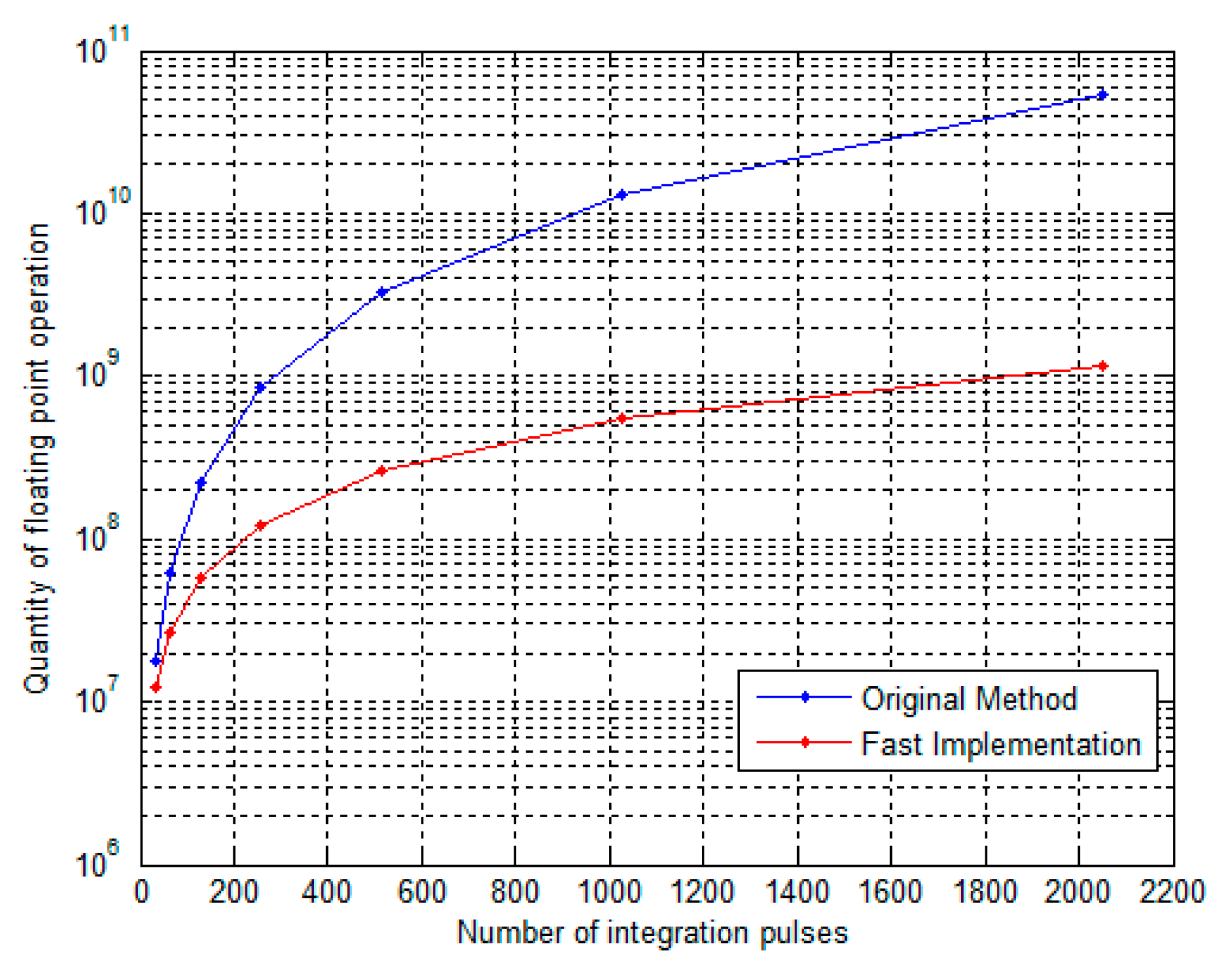
3.3. Computation Complexity Analysis

In this section, computational complexity of the proposed algorithm is discussed, and the engineering application evaluation is carried out based on the processing ability of a typical modern digital signal processor (DSP).
Suppose that Nr and Nv are the range unit number and velocity unit number respectively, then the computing load may be given in Table 1 where P = M + Nv, where Im represents the complex multiplication operation and Ia represents the complex addition operation.
Then the quantity of floating-point operations is used to evaluate the computing load. The computing load for different pulse numbers M are shown in Figure 3. It can be seen that the fast implementation of the proposed method can reduce the computational complexity significantly. When M = 2048, the computing load of the fast implementation approach is only about 3.2% of the original proposed method.
Suppose that Nr = 1024, M = 2048, the velocity unit number Nv is equal to M, Tr = 20 µs, and the CPI = 41 ms. The computation amount of a real floating-point operation is 1.2 × 10⁹. Taking the typical DSP, TMS320C6678 from Texas Instruments, as an example, the floating-point computing ability is 160 GFLOPS [19], only 7.3 ms are needed to implement the above processing, which is sufficient to meet the real-time processing requirements.
In some radar using the median pulse-repetition frequency (MPRF) or low pulse-repetition frequency (LPRF), the target velocity is usually ambiguous and then Nv is often Q times as M. The real operation number increases with the expansion of the velocity matching range. Taking Q = 4 as an example, the range of velocity matching can be increased 4 times by only increasing 30% of the computation. Therefore, the proposed fast method cannot only effectively reduce the computational complexity, but also achieve the coherent integration for wideband radar with a larger range of matching velocity at a smaller cost.

4. Numerical Experiment

4.1. Simulation Results

The simulation parameters are listed in Table 2. The radar signal bandwidth B = 100 MHz and the corresponding range resolution is 1.5 m. As shown in Figure 4a, the ARU is 6.1 m across 4 range units in the CPI of 512 pulses while the ADU is also 4 Doppler units and equivalent to the ARU.
The integration result based on the conventional FFT process is shown in Figure 4b. The integration performance decreases seriously without compensation for ARU and ADU, and the target amplitude after coherent integration is only 13.7 × 10⁴. The integration results based on the two-dimensional frequency correction and its fast implementation are shown in Figure 4c,d respectively. The velocity search range is [−625 m/s, 625 m/s] with interval of 2.44 m/s, and it can be seen that the target peaks appear at 300 m/s accurately with the amplitude of 5.1 × 10⁵ and 5.0 × 10⁵, which are nearly equal to the theoretical value.
The comparison of the target’s Doppler profile and range profile are shown in Figure 5 to clarify the integration results, and the amplitude is converted into logarithmic representation. It can be seen that the target is broadened in the result of conventional FFT. The results of the proposed methods prove that the ARU and ADU of the target can be corrected by the two-dimensional frequency correction and achieve coherent integration effectively, and the improvements to SNR are 10.9 dB and 11.1 dB, respectively. The integration result of the fast implementation is slightly higher than that of the direct method for avoiding the loss of amplitude and phase in Doppler unit re-alignment processing.

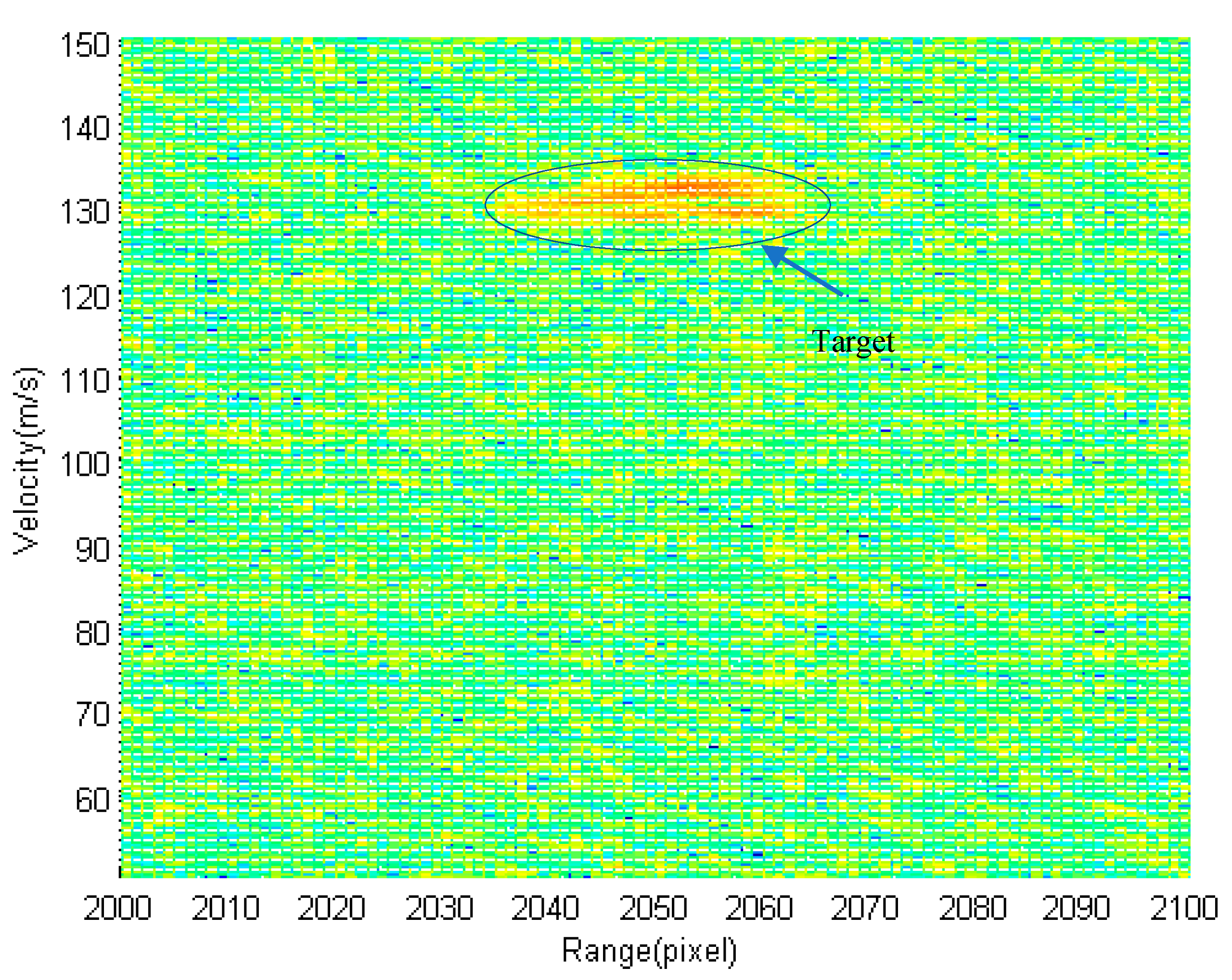
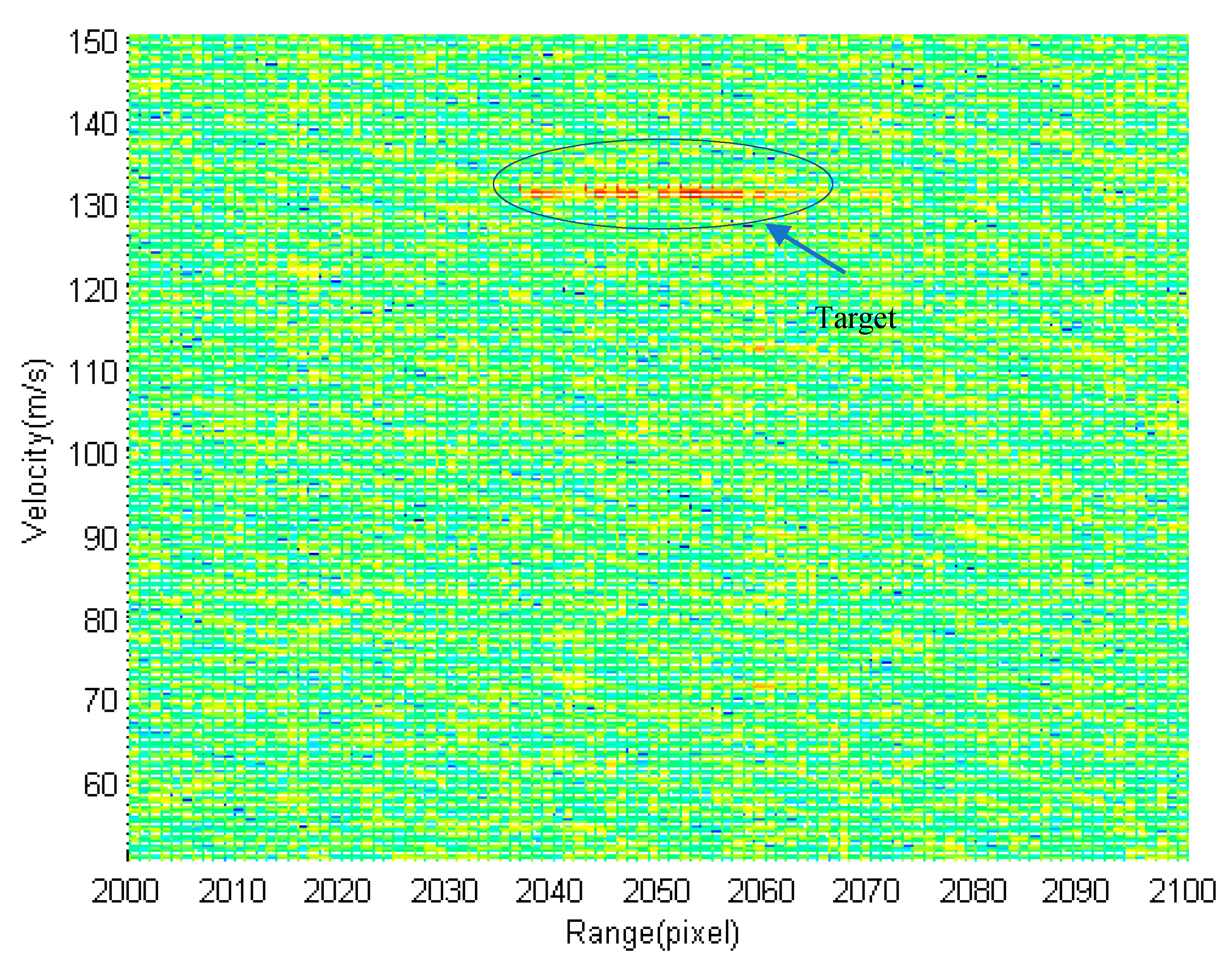
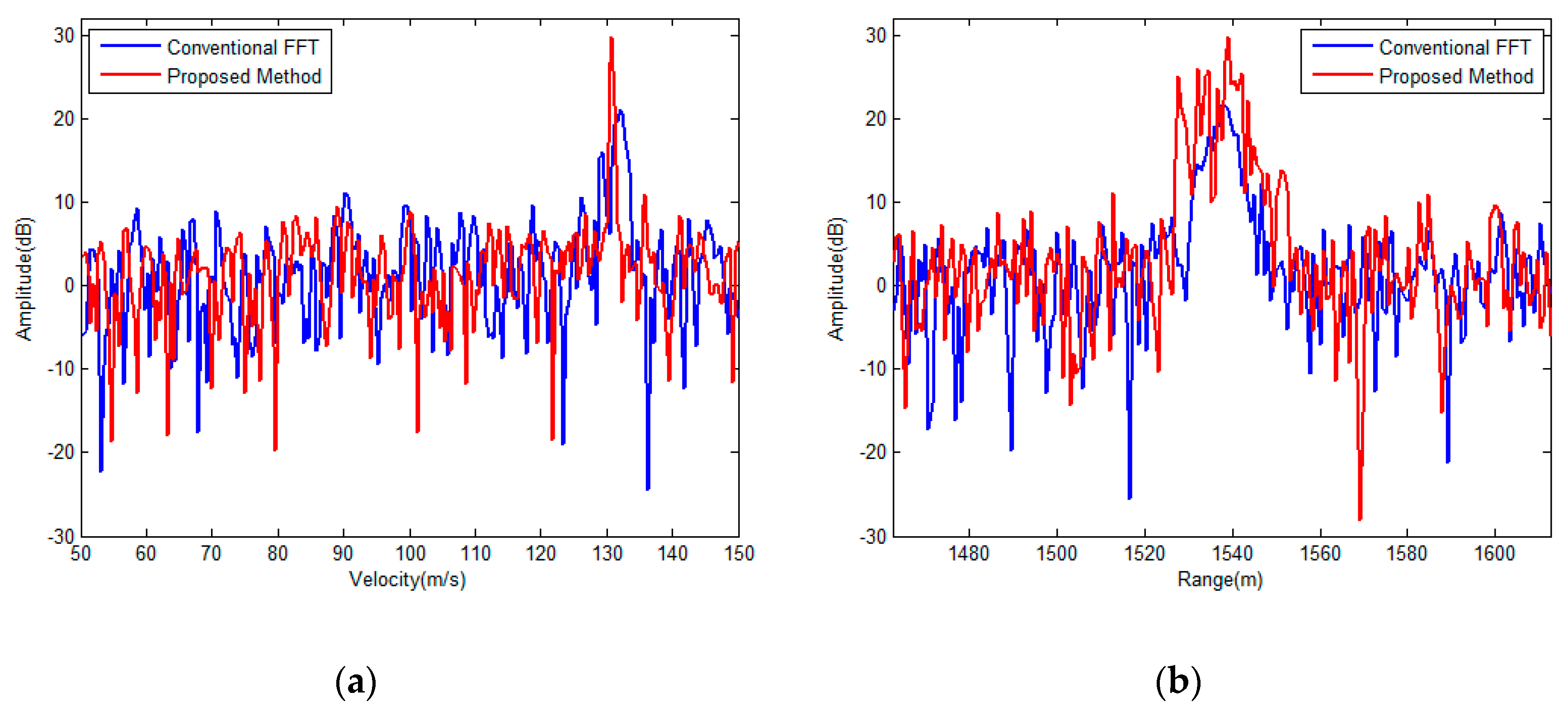
4.2. Measured Data Results

The proposed algorithm is further validated by the measured data. The parameters of the real radar and the target aircraft for the experiment are shown in Table 3.
The result of conventional FFT is shown in Figure 6. The target is significantly broadened in the range-velocity plane due to the influence of ARU and ADU which are about 7 units and match the theoretical value approximately. The Doppler frequency has been converted to the corresponding velocity value for comparison. The result based on the proposed fast implementation method is shown in Figure 7. The velocity search range is [50 m/s, 150 m/s] and the velocity search interval is 0.39 m/s corresponding to the Doppler resolution. It can be seen that coherent integration is effectively achieved with great SNR improvement compared to that of the conventional method.
The high-resolution range profile (HRRP) and the Doppler profile of the target are shown in Figure 8a,b respectively. The evaluation the integration results are listed in Table 4. The SNR improvement of the proposed integration method is up to 9.6 dB compared with that of the conventional integration method. The HRRP of the target is nearly distributed over 38 range units and the corresponding radial length is about 28 m.

5. Conclusions

A coherent integration method for the wideband radar is proposed in this paper based on two-dimensional frequency correction. The algorithm realizes the motion compensation by the data re-alignment in the fast-time frequency-Doppler domain, and achieves the intra-pulse accumulation and the inter-pulse integration in the transform domain. The simulation and measured data results show that the proposed method can compensate the target motion and achieve coherent integration for wideband signals without any prior information of the number and velocities of the targets in the case of velocity ambiguity. An efficient approach is also proposed which equates the time-delay addressing operation in fast-time frequency-Doppler domain with the phase compensation in the fast-time frequency-slow time domain. It resolves the requirement that the time-delay addressing operation in the two-dimensional matrix cannot be processed into row or column regularization, and avoids the computational burden of interpolation introduced to improve the accuracy of integer operation. The work in this paper provides a new and effective way for the coherent integration of wideband radar signals and is easy to implement in engineering.

Author Contributions

Conceptualization, S.S. and L.T.; methodology, S.S. and L.L.; validation, S.S. and X.N., resources, X.Z.; writing—original draft preparation, S.S.; writing—review and editing, Y.B. and L.T.; supervision, X.Z. and D.B. All authors have read and agreed to the published version of the manuscript.

Funding

This research was funded by National Natural Science Foundation of China, grant number 61976113.

Conflicts of Interest

The authors declare no conflict of interest.

References

  1. Wehner, D.R. High-Resolution Radar, 2nd ed.; Artech House: Boston, MA, USA, 1995. [Google Scholar]
  2. Liu, H.W.; Du, L.; Bao, Z. Progressing radar automatic target recognition based on high range resolution profile. J. Electron. Inf. Technol. 2005, 27, 1328–1334. [Google Scholar]
  3. Loomis, J.M. Army radar requirements for the 21st century. In Proceedings of the 2007 IEEE Radar Conference, Boston, MA, USA, 17–20 April 2007; pp. 1–6. [Google Scholar]
  4. Skolnik, M.I.; Linde, G.; Meads, K. An advanced wideband air-surveillance. IEEE Trans. Aerosp. Electron. Syst. 2001, 37, 1163–1175. [Google Scholar] [CrossRef]
  5. Richards, M.A. Coherent integration loss due to white Gaussian phase noise. IEEE Signal Process. Lett. 2003, 10, 208–210. [Google Scholar] [CrossRef]
  6. Wang, J.; Zhang, S.H. Study on the motion compensation of range migration for weak moving target detection. Chin. J. Electron. 2000, 28, 56–59. [Google Scholar]
  7. Li, H.; Wu, S.; Mo, L. A method for long-term signal integral detection of weak targets. J. Beijing Inst. Technol. 2001, 21, 614–617. [Google Scholar]
  8. Carlson, B.D.; Evans, E.D.; Wilson, S.L. Searching radar detection and track with the Hough transform–Part I: System concept. IEEE Trans. Aerosp. Electron. Syst. 1994, 30, 102–108. [Google Scholar] [CrossRef]
  9. Carlson, B.D.; Evans, E.D.; Wilson, S.L. Searching radar detection and track with the Hough transform–Part II: Detection statistics. IEEE Trans. Aerosp. Electron. Syst. 1994, 30, 109–115. [Google Scholar] [CrossRef]
  10. Carlson, B.D.; Evans, E.D.; Wilson, S.L. Searching radar detection and track with the Hough transform–Part III: Detection performance with binary integration. IEEE Trans. Aerosp. Electron. Syst. 1994, 30, 116–125. [Google Scholar] [CrossRef]
  11. Perry, R.P.; Dipietro, R.C.; Fante, R.L. Coherent integration with range migration using Keystone formatting. In Proceedings of the 2007 IEEE Radar Conference, Boston, MA, USA, 17–20 April 2007; pp. 863–868. [Google Scholar]
  12. Zhang, S.S.; Zeng, T. Dim target detection based on Keystone transform. In Proceedings of the IEEE International Radar Conference 2005, Arlington, VA, USA, 9–12 May 2005; pp. 889–894. [Google Scholar]
  13. Li, Y.; Zeng, T.; Long, T. Range migration compensation and Doppler ambiguity resolution by Keystone transform. In Proceedings of the 2006 CIE International Conference on Radar, Shanghai, China, 16–19 October 2006; pp. 1–4. [Google Scholar]
  14. Mahafza, B.R. Radar Systems Analysis and Design Using Matlab, 2nd ed.; CRC Press: Boca Raton, FL, USA, 2005. [Google Scholar]
  15. Ian, G.C.; Frank, H.W. Digital Processing of Synthetic Aperture Radar Data Algorithms and Implementation; Publishing House of Electronics Industry: Beijing, China, 2019; pp. 70–73. [Google Scholar]
  16. Lin, M.Y.; Ke, T.N. Radar Signal Theory; Publishing House of Defense Industry: Beijing, China, 1984. [Google Scholar]
  17. Yuan, H.J.; Gao, M.G.; Mou, J.C. Multi-frame Stepped-Frequency Signal Processing Based on Doppler Bin Alignment. J. Electron. Inf. Technol. 2009, 31, 1659–1663. [Google Scholar]
  18. Lanari, R.; Hensley, S.; Rosen, P. Chirp Z-transform based SPECAN approach for phase-preserving ScanSAR image generation. IEE Proc. Radar Sonar Navig. 1998, 14, 254–261. [Google Scholar] [CrossRef]
  19. Texas Instruments, Inc. TMS320C6678 Multicore Fixed and Floating-Point Digital Signal Processor: Data Manual, Texas Instruments; Texas Instruments, Inc.: Dallas, TX, USA, 2010. [Google Scholar]
Figure 1. Doppler distribution in fast-time frequency domain.
Electronics 09 00840 g001
Figure 2. Block diagram of the proposed algorithm.
Electronics 09 00840 g002
Figure 3. The comparison of computing load for different pulse numbers.
Electronics 09 00840 g003
Figure 4. Simulation result. (a) Across range unit (ARU) and across Doppler unit (ADU) of the echo data; (b) integration result of conventional FFT; (c) result of the proposed algorithm; (d) result of the proposed fast implementation method.
Electronics 09 00840 g004
Figure 5. Comparison of the integration results. (a) Comparison of Doppler profiles; (b) comparison of range profiles.
Electronics 09 00840 g005
Figure 6. Coherent result of conventional FFT.
Electronics 09 00840 g006
Figure 7. Coherent result of proposed method.
Electronics 09 00840 g007
Figure 8. Comparison of the integration results. (a) Comparison of Doppler profiles; (b) comparison of range profiles.
Electronics 09 00840 g008
Table 1. Computing load analysis.
ProcessingComputation Complexity
Fast-time FFT[(1/2Nrlog2(Nr))Im + (Nrlog2(Nr))Ia]Na
Frequency domain matchingNrNaIm
Chirp-Z Transform (CZT)[(2P + 3/2Plog2(P))Im + (3Plog2(P))Ia]Nr
Fast-time IFFT[(1/2Nrlog2(Nr))Im + (Nrlog2(Nr))Ia]Nv
Table 2. Simulation parameters.
ParametersValue
Carrier frequency (fc)3.0 GHz
Signal bandwidth (B)100 MHz
pulse repetition interval (PRI)40 µs
Number of range units (M)3072
Number of pulses (N)512
Target velocity (vc)300 m/s
Table 3. Experiment parameters.
ParametersValue
Carrier frequency (fc)10.0 GHz
Signal bandwidth (B)200 MHz
Pulse repetition interval (PRI)150 µs
Number of range units (M)2500
Number of pulses (N)256
Target velocity (vc)131 m/s
Table 4. Evaluation of the integration results.
Range ResolutionVelocity ResolutionSignal-to-Noise Ratio (SNR) Comparison
Conventional FFTProposed MethodImprovement
0.75 m0.39 m/s20.2 dB29.8 dB9.6 dB

