Abstract
For the last four decades, several steering systems for vehicles such as active front steering (AFS), front wheel independent steering (FWIS), 4-wheel steering (4WS) and 4-wheel independent steering (4WIS) have been proposed and developed. However, there have been few approaches for comparison among these steering systems with respect to yaw rate tracking or path tracking performance. This paper presents comparison among AFS, FWIS, 4WS and 4WIS in terms of vehicle stability control. In view of vehicle stability control, these systems are used as an actuator for generation of yaw moment. Direct yaw moment control is adopted to calculate a control yaw moment. Distribution from the control yaw moment into tire forces is achieved by a control allocation method. From the calculated tire forces, the steering angles of FWIS, 4WS and 4WIS are determined with a lateral tire force model. To check the performance of these actuators, simulation is conducted on vehicle simulation packages, CarSim. From the simulation, the advantages of FWIS and 4WIS are revealed over AFS and 4WS.
1. Introduction
Various types of steering system for passenger vehicles have been proposed and developed over the past 60 years [1]. Let the steering system with rack and pinion mechanism installed on front wheels be called the conventional steering system (CSS). Other than CSS, the first proposal was a 4-wheel steering (4WS) system, which was commercialized in the early 1980s. It combined CSS with a rear-wheel steering (RWS) system. However, the system was not widespread. In 2004, an active front steering (AFS) system was developed [2]. Additionally, from this time on, an active rear steering (ARS) system or RWS was developed again [3].
In case of independent steering system, the steering angles of the left and right wheels can move independently of each other. This was proposed in the field of mobile robots [4,5,6]. In the area of vehicle engineering, a front wheel independent system (FWIS), including a steer-by-wire (SBW) system, was developed [7,8,9]. Since the late 2000s, a four-wheel independent drive (4WID) system with no axle connection, such as an in-wheel motor, has been developed and mounted on a real vehicle [10,11]. Following the development of in-wheel motors, studies have been conducted to apply a four-wheel independent steering (4WIS) system to real vehicles [12,13,14,15,16,17]. In addition to the in-wheel motor-driven systems, the rear wheel independent steering (RWIS) system was developed in 2016 [18].
In the past 30 years, several researches on the application of AFS or RWS or 4WS have been conducted in the field of vehicle stability control [19,20,21,22,23]. For vehicle stability control, these devices have been used to generate a control yaw moment, which is required to keep a vehicle stable. If these devices are used for vehicle stability control, there are several advantages over an electronic stability control (ESC) that uses braking inputs [20]. For example, when generating the control yaw moment, the speed of the vehicle slightly decreases because the steering is used instead of braking. In addition, the steering system is easier to control than the braking system. The drawback of using those steering actuators is that the side-slip angle increases due to large speed and lateral acceleration. This can be overcome by using RWS or ARS. Most of those studies were carried out in order to verify the effectiveness of AFS, RWS, 4WS, combined with ESC and torque vectoring device (TVD), in maintaining the lateral stability of the vehicle [22,23]. From a control point of view, SBW and AFS play the same role. However, there have been few studies on FWIS for vehicle stability control so far [8,9]. On the other hand, there have been several studies dealing with 4WIS [10,11,12,13,14,15,16,17]. Generally, 4WS and 4WIS are superior to AFS because AFS has little effect on vehicle stability if the lateral tire forces of front wheels are saturated. A RWS in 4WS and 4WIS makes it possible to prevent the saturation of the lateral tire forces at the front wheels [18].
There have been several approaches that have applied 4WIS to vehicle stability control [10,11,12,13,14,15,16,17]. In the previous study, the control yaw moment was computed with sliding mode control [10]. To generate the control yaw moment in real vehicles, the steering angles of 4WIS, combined with ESC and TVD, were determined by quadratic optimization with equality constraints [10]. This is common approach in the previous work [20,21,22,23]. On the other hand, the steering angles of 4WIS were directly determined by a controller or kinematics [11,12,13,14,15,16,17]. In this research, LQ optimal controller and fuzzy logic parameter adjusters were adopted to determine the steering angles of 4WIS, and feedforward and PID control were adopted for TVD [11]. Like [10], the steering and traction devices were used as an actuator in the research. In another study, the steering angles of 4WIS or RWS and the traction torques of hub motors were calculated with the μ-synthesis technique [12,13]. These studies adopted the steering and the braking/traction as actuators for yaw moment generation [10,11,12,13]. This is called an integrated chassis control. In contrast, some researches adopted only the steering actuators. In the work of [14], the rear steering or toe angles in 4WIS system were determined by feedback with front steering angle and yaw rate signals. This is common in vehicle stability control with 4WS [18]. In another study, PID control was adopted to determine the steering angles for position and kinematic constraint controller [15]. In another study, the steering angles of 4WIS were determined by kinematic relationship without controller design procedure for path tracking [16,17].
As described in the above reference survey, there have been two categories of applying 4WIS to vehicle stability control. The first is to combine 4WIS with ESC and TVD. The second is to use only 4WIS. Among them, there have been few approaches comparing the performance of 4WIS with other devices such as ESC and TVD or AFS, ARS and 4WS. In the previous research, AFS, ARS and 4WS have been compared to one another in view of vehicle stability control [21]. However, there have been few approaches comparing 4WIS with AFS, FWIS and 4WS. Therefore, it is necessary to compare these steering actuators with one another in terms of vehicle stability control.
In this paper, the effects of AFS, FWIS, 4WS and 4WIS on vehicle stability control were compared in terms of maneuverability and lateral stability. To this end, a vehicle stability controller is designed as given in the previous work [10,21,22,23]. The controller is composed of an upper-level controller and a lower-level controller. The upper-level controller computes the control yaw moment required to stabilize the vehicle by applying controller design methodology to a vehicle model. The control yaw moment computed by the upper-level controller is converted into tire forces and back to the steering angle of each wheel. The methods of converting tire forces to steering angles for AFS, FWIS, 4WS, 4WI are proposed. To check the performance for AFS, FWIS, 4WS, and 4WIS in terms of vehicle stability control, simulation is conducted in the vehicle simulation package, CarSim.
This paper is organized into four sections. Section 2 explains how to design the vehicle stability controller, i.e., upper- and lower-level controllers. The methods used for determining the steering angles of the steering actuators from tire forces are given in Section 3. The simulation is carried out and the results are given in Section 4. The conclusions are drawn in Section 5.
2. Design of a Vehicle Stability Controller
2.1. Upper-Level Controller: Direct Yaw Moment Control
For controller design, a vehicle model is needed. Several types of vehicle models have been used for controller design. Typical vehicle models for vehicle stability control are 3-DOF planar and 2-DOF bicycle ones. The 3-DOF planar model has longitudinal, lateral and yaw dynamics [24]. Therefore, a tire model, which can calculate the longitudinal and lateral tire forces, is needed. On the other hand, the 2-DOF bicycle model has no longitudinal dynamics. Therefore, only a lateral tire force model is needed for it. Moreover, it is much simpler than the 3-DOF planar model [20,21,22,23]. For this reason, the most frequently used model in vehicle stability control is a 2-DOF bicycle one. Therefore, a 2-DOF bicycle model is used to design a yaw moment controller in this paper.
Figure 1 shows the model. There are two motions in the model: yaw and lateral motions. It is assumed that the longitudinal velocity vx is constant. Therefore, the state variables of the model are the yaw rate, γ, and the side-slip angle, β. With these state variables, the equations of motion for the model are given as Equation (1). In Equation (1), ΔMB is the control input, i.e., the control yaw moment that is to be generated for vehicle stability. The tire slip angles αf and αr are calculated with γ, β, and vx as Equation (2). In Equation (1), it is assumed that the lateral tire forces, Fyf and Fyr, of front and rear wheels are nonlinear functions of the tire slip angles, αf and αr, as shown in Equation (3), respectively [23]. The reference yaw rate, γd, is algebraically calculated from the steering angle of front wheels, δf [21].
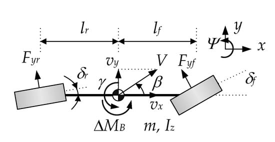
Figure 1.
2-DOF bicycle model.
There are two objectives for vehicle stability control: maneuverability and lateral stability. The maneuverability means that a vehicle follows the driver’s intention. The driver’s intention is represented as γd. Therefore, the difference between γ and γd of a vehicle should be zero to satisfy the maneuverability. The lateral stability means small β. According to the previous research, β should be smaller than 3° [21]. Moreover, it is desirable to maintain β as small as possible. On low-friction surfaces, it is not difficult to satisfy the maneuverability with a controller. However, β can diverge under that situation although the maneuverability is satisfied [25]. Therefore, β is to be reduced to as small as possible for lateral stability. For that purpose, a phase plane, which is drawn with the side-slip angle and its rate, was adopted in the previous research [24]. On the phase plane, the region of lateral stability was defined near the origin.
To achieve these objectives, a vehicle stability controller should make the difference between γ and γd zero and keep β as small as possible. For this purpose, the error is defined as in Equation (4). In Equation (4), η is the tuning parameter, used to compromise between the yaw rate error, i.e., γ − γd, and β. To make the error zero, the stability condition, as given in Equation (5), is to be satisfied [21,22,23]. From Equations (4), (5) and (1), ΔMB is obtained, as in Equation (6).
In Equation (6), the lateral tire forces, Fyf and Fyr, and β are hard to measure. Moreover, a wheel force transducer, used to measure the tire forces, is very expensive. Therefore, it is necessary to estimate those signals with some observers or estimators. In this paper, the lateral tire forces are estimated with a sliding mode observer, as given in [26]. The side-slip angle is estimated with signal-based extended Kalman filter [27].
2.2. Low-Level Controller: Yaw Moment Distribution with Control Allocation
Once ΔMB is calculated in the direct yaw moment controller, the tire forces of the steering actuators are to be determined, which are required to generate ΔMB. Figure 3 shows the free-body diagram of the lateral tire forces and ΔMB if ΔMB is positive. In Figure 3, Fy1, Fy2, Fy3 and Fy4 are the lateral tire forces generated by the steering actuators at wheel1, wheel2, wheel3, and wheel4, respectively. It is necessary to determine these forces for generating ΔMB. For this purpose, a control allocation method is needed. In this paper, the weighted pseudo-inverse-based control allocation (WPCA) is adopted as a control allocation method [22,28].
In Figure 2, the steering angles, δ1, δ2, δ3, and δ4, of each wheel can be set for each actuator. For example, the steering angles are set to δ1 = δ2, δ3 = δ4 = 0 if AFS is adopted as an actuator. Based on that fact, the steering angles are set as shown in Equation (7). These steering angles are calculated from the lateral tire forces, Fy1, Fy2, Fy3 and Fy4. Among these, AFS and 4WS have been combined with ESC or TVD for vehicle stability control in the previous research [20,21,22,23].
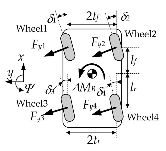
Figure 2.
Free-body diagram of the tire forces and the control yaw moment.
Equation (8) shows the force-moment equilibrium between Fy1, Fy2, Fy3, Fy4 and ΔMB, given in Figure 2 [21]. The objective function of WPCA is defined in Equation (9). The objective function, Equation (9), is used to minimize the lateral tire forces satisfying Equation (8).
The optimization problem in WPCA is the quadratic programming with Equations (9) and (8). With the Lagrange multiplier technique, the optimum, zopt, can be algebraically calculated as in Equation (10). If one expands Equation (10), the optimum solution can be easily calculated without matrix inverse computation.
The objective function and the equality constraint, i.e., Equations (9) and (8), are relevant to 4WIS. Therefore, if another steering actuator is used, then they should be modified according to the steering actuators as given in Equation (7). For example, if AFS is used, then Equation (8) is reduced into Equation (11). This case does not need an optimization procedure, because the solution can be easily calculated, i.e., Fy = ΔMB/2a1 = ΔMB/2a2. If FWIS and 4WS are used, then the objective function and the equality constraint are given in Equations (12) and (13), respectively.
3. Determination of Steering Angles from Lateral Tire Forces
After calculating the optimum solution from the WPCA, each lateral tire force is to be converted into the corrective steering angle of each steering actuator. Braking pressures of ESC are easy to calculate based on the longitudinal tire forces using a simple formula. Compared to the braking pressure, the corrective steering angles of AFS, FWIS, 4WS and 4WIS are not easy to calculate from lateral tire forces.
To find the corrective steering angle of each actuator, it is necessary to calculate the tire slip angle from the tire lateral forces obtained by the optimum solution of WPCA. After finding the tire slip angle, the corrective steering angle can be calculated using Equation (2). There are five methods to do this.
The first method is to use the linear model of lateral tire force, as given in Equation (14). Using this, the corrective steering angle is calculated as in Equation (15) [29]. In Equation (15), Ci is the cornering stiffness of each wheel, and Δδi is the corrective steering angles of steering actuators, which is added to the driver’s steering angle or the current rear steering angle, δi. σ is a parameter used to tune the magnitude of the cornering stiffness. Generally, the smaller the σ, the better the control performance, because it generates larger corrective steering angles. With Equation (15), the nonlinear relationship between the tire slip angle and the lateral tire force is neglected in this formula. Let the first method be denoted as Method#1.
The second method is to use Equation (2) [30]. Equation (2) is converted into Equation (16). From Equation (16), the corrective steering angle Δδi of each wheel is calculated as Equation (17). As shown in Equation (17), it is necessary to find the slip angle in order to calculate the corrective steering angle. In the second method, the tire slip angle is calculated using Equation (18) from the linear tire force model, i.e., Equation (14). In Equation (18), the constant cornering stiffness is used to calculate the tire slip angle. Therefore, this is valid for the linear region under a certain value of tire slip angle. Let the second method be denoted as Method#2.
The third method is to use an inverse of lateral tire force model. Equations (19)–(21) show the exponential, hyperbolic tangent and saturation tire models, respectively [31]. There are two tuning parameters, Cα and κ, in these models if the tire–road friction coefficient μ, the vertical tire force Fz, and tire slip angle α are given. Figure 3 shows the fitting results of these models to CarSim data [32]. As shown in Figure 3, the exponential and hyperbolic tangent models are well fitted.
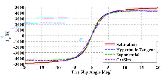
Figure 3.
Fitting results of lateral tire force models for CarSim data.
If the lateral tire force Fyi of each wheel is given from the optimum solution of WPCA, it is necessary to find the tire slip angle with the inverse of the lateral tire force model. As shown in Equation (22), it is easy to find the inverse of the hyperbolic tangent model from Equation (20). It is also easy to find the inverses of the other models, given in Equations (19) and (21). After calculating the tire slip angle αi of each wheel with the inverse of tire force model, the corrective steering angle of each wheel is calculated with Equation (17). Let the third method be denoted as Method#3.
The fourth and fifth methods are to use the estimated cornering stiffness in Equations (15) and (18). For the purpose, the first step is to estimate β with the method given in [27]. Then, the tire slip angle is calculated with the estimated β in Equation (16). At this moment, the corrective steering angle, Δδi, is set to zero. With the calculated tire slip angle, the lateral tire force is calculated from the models, as given in Equations (19), (20) or (21). Finally, the cornering stiffness is calculated by dividing the lateral tire force by the calculated tire slip angle. With the estimated cornering stiffness, the corrective steering angle of each wheel is calculated from Equations (15) and (18). The fourth and fifth methods are to use Equations (15) and (18), respectively. In this paper, the hyperbolic tangent model is used to estimate the tire slip angle and the cornering stiffness, because it is simple and reflects the nonlinear relationship between the tire slip angle and the lateral tire force [32]. Let the fourth and fifth methods be denoted as Method#4 and Method#5, respectively.
4. Simulation
In this section, simulation was done to compare the performance of the vehicle stability control with AFS, FWIS, 4WS and 4WIS. The simulation was conducted on CarSim [33]. The simulation scenario was closed-loop steering on the moose test track, because cornering on the track is so drastic that other scenarios such as sine-with-dwell and step steer can be covered by it [22,23]. The vehicle type used in the simulation was a D-class sport utility vehicle (SUV), provided in CarSim [33]. The parameters of the D-class SUV are given in Table 1.

Table 1.
Parameters and values of D-Class SUV in CarSim.
The simulation environment was identical to that in [21]. The steering input was generated by the CarSim driver model, which is the implementation of [34]. The driver’s preview time was set to 0.75 sec, which indicates an unpracticed driver [21]. The initial vehicle speed and the tire–road friction coefficient were set to 80 km/h and 0.6, respectively. There were no control actions to keep constant speed. The steering actuators, i.e., AFS, FWIS, 4WS and 4WIS, were modeled as a first-order system with a time constants of 0.05. There were no braking-based ESCs or traction-based TVDs.
Figure 4 and Figure 5 show the simulation results and the corrective steering angles for each steering actuator. In the simulation, Method#1 was used to determine the corrective steering angles for each actuator, because it is the simplest among the methods. In Figure 5, the legends FL, FR, RL and RR represent the front left, front right, rear left and rear right wheels, respectively. In this paper, the maneuverability is checked with FMVSS 126, which requires the yaw rate error to be less than 0.08 rad/s or 4.58 deg/s. The lateral stability is checked by the condition that β is less than 3° [35].
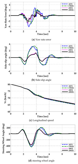
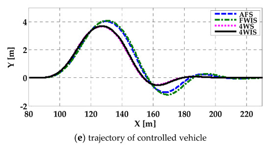
Figure 4.
Simulation results for each steering actuator.
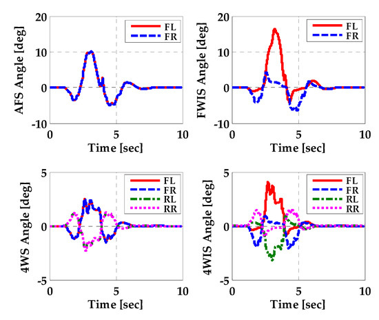
Figure 5.
Corrective steering angles of each actuator.
Without control, the vehicle lost its stability because the tire–road friction coefficient was low and the vehicle speed was high. In other words, the steering wheel angle, the yaw rate and the side-slip angle of the uncontrolled vehicle diverged. In contrast to this case, the controlled vehicles maintained their stability. Figure 4a,b shows that the controlled vehicles with 4WS and 4WIS satisfy the FMVSS 126 criteria. On the other hand, the vehicles with AFS and FWIS cannot satisfy the lateral stability criteria. As shown in Figure 4c, the vehicle speeds are nearly identical to one another among steering actuators because there are no braking inputs. Figure 4a shows that the yaw rate errors of FWIS and 4WIS are slightly better than those of AFS and 4WS, respectively. This means the fact that the independent steering actuators, FWIS and 4WIS, are superior to AFS and 4WS. As shown in Figure 4b, the most notable feature of 4WS and 4WIS is that the side-slip angle is reduced by them, compared to AFS and FWIS. This is the effect of rear wheel steering (RWS), as pointed out in [21,32]. Other effects of RWS are the smaller steering wheel angle and lateral offset error from the centerline of the road, as shown in Figure 4d,e. Moreover, RWS makes the convergence of steering wheel angle and lateral offset error faster.
The magnitudes of the steering angle of 4WS and 4WIS are smaller than those of AFS and FWIS, as shown in Figure 5. This is caused by the use of RWS and RWIS in 4WS and 4WIS, respectively. Moreover, the direction of RWS is opposite to that of AFS in case of 4WS and 4WIS, as shown in Figure 5. This has been a widely adopted method in applying RWS to vehicle stability control [14,18,32]. The results given in Figure 5 show the advantage of FWIS and 4WIS over AFS and 4WS, respectively. For FWIS and 4WIS, the steering angle of front inner wheel should be larger than that front outer one when cornering. FWIS and 4WIS can give better control performance than AFS and 4WS because it can generate larger lateral tire forces, as shown in Figure 5.
To compare the steering actuators and the methods of determining the corrective steering angles, three measures were considered: the maximum absolute yaw rate error (MAYRE), the maximum absolute side-slip angle (MASSA), and the maximum absolute lateral offset error (MALOE) over the simulation period. The MAYRE and MASSA represent the maneuverability and the lateral stability, respectively. These measures were calculated after simulation for the period from 0 to 10 secs. Table 2, Table 3 and Table 4 show MAYRE, MASSA, and MALOE for each steering actuator and the method of corrective steering angle determination. In view of maneuverability or MAYRE, 4WIS with Method#1 is the best combination, as shown in Table 2. In view of lateral stability or MASSA, 4WIS with Method#1 or Method#4 is the best combination. In view of MALOE, 4WIS with Method#1 or Method#4 is the best combination. From the overall perspective, 4WIS with Method#1 is the best combination, and Method#4 is the best regardless of the selection of steering actuators.
Table 2.
Maximum absolute yaw rate error for each actuator and method.
Table 3.
Maximum absolute side-slip angle for each actuator and method.
Table 4.
Maximum absolute lateral offset error for each actuator and method.
5. Conclusions
In this paper, active steering systems such as AFS, FWIS, 4WS and 4WIS were compared in terms of vehicle stability control. The direct yaw moment control was adopted to compute the control yaw moment. The WPCA was used to calculate the optimal tire forces, required to generate the control yaw moment. Five methods were proposed to determine the corrective steering angles of AFS, FWIS, 4WS and 4WIS from the optimal tire forces of WPCA. To check the performance of those actuators, simulation was conducted on CarSim. From the simulation results, it can be concluded that the greater the number of actuators, the better the control performance. In other words, FWIS and 4WIS were superior to AFS and 4WS, respectively. In particular, 4WIS with Method#1 was identified as the best combination, and Method#4 was identified as the best regardless of the selection of steering actuators. This conclusion implies that the independent steering systems, i.e., FWIS and 4WIS, can improve the performance of vehicle stability control. Moreover, 4WIS can be adopted for path tracking in autonomous driving instead of pure pursuit or Stanley methods [36].
Funding
This research was funded by the National Research Foundation of South Korea (NRF) Grant funded by the Korean Government through the Ministry of Education under Grant 2019R1A6A1A03032119.
Conflicts of Interest
The authors declare no conflict of interest.
Nomenclature
| Cf, Cr | cornering stiffness of front/rear tires (N/rad) |
| Ci | cornering stiffness of each wheel (N/rad) |
| Fy | lateral tire force (N) |
| Fz | vertical tire force (N) |
| Iz | yaw moment of inertial (kg⋅m2) |
| K | gain in sliding mode control |
| lf, lr | distance from C.G. to front and rear axles (m) |
| m | vehicle total mass (kg) |
| tf, tr | half of track widths of front and rear axles (m) |
| vx, vy | longitudinal and lateral velocities of a vehicle (m/s) |
| αf, αr | tire slip angles of front and rear wheels (rad) |
| αi | tire slip angle of each wheel (rad) |
| β | side-slip angle (rad) |
| δf,δr | front and rear steering angles (rad) |
| δi | current steering angle of each wheel (rad) |
| Δδi | corrective steering angle of each wheel (rad) |
| ΔMB | control yaw moment (Nm) |
| γ, γd | real and reference yaw rates (rad/s) |
| η | tuning parameter on yaw rate error and side-slip angle |
| μ | tire–road friction coefficient |
References
- Furukawa, Y.; Yuhara, N.; Sano, S.; Takeda, H.; Matsushita, Y. A review of four-wheel steering studies from the viewpoint of vehicle dynamics and control. Veh. Syst. Dyn. 1989, 18, 151–186. [Google Scholar] [CrossRef]
- Klier, W.; Reimann, G.; Reinelt, W. Concept and Functionality of the Active Front Steering System 2004-21-0073; SAE: Warrendale, PA, USA, 2004. [Google Scholar]
- Nissan Motor Company, 4 Wheel Active Steer (4WAS). Available online: https://www.nissan-global.com/EN/DOCUMENT/PDF/TECHNOLOGY/TECHNICAL/4was_en.pdf (accessed on 4 April 2020).
- Makatchev, M.; Lang, S.Y.T.; Tso, S.K.; McPhee, J.J. System design, modeling, and control of a four-wheel-steering mobile robot. In Proceedings of the 19th Chinese Control Conference, Hong Kong, China, 6–8 December 2000; pp. 759–763. [Google Scholar]
- Santana, P.F.; Candido, C.; Santos, V.; Barata, J. A motion controller for compliant four-wheel-steering robots. In Proceedings of the 2006 IEEE International Conference on Robotics and Biomimetics, Kunming, China, 17–20 December 2006; pp. 532–537. [Google Scholar]
- Ye, Y.; He, L.; Zhang, Q. Steering control strategies for a four-wheel-independent-steering bin managing robot. IFAC-PapersOnLine 2016, 49, 39–44. [Google Scholar] [CrossRef]
- Yih, P. Steer-by-Wire: Implications for Vehicle Handling and Safety. Ph.D. Thesis, Stanford University, Stanford, CA, USA, January 2005. [Google Scholar]
- Ahmed, A.K.W.; Bhat, R.B. Active front independent steering system and its control for road vehicle with understeer characteristics. In Proceedings of the International Conference on Advances in Electrical and Mechanical Engineering, Phuket, Thailand, 18–19 December 2012. [Google Scholar]
- Rawat, V. Active Independent Front Steering for Yaw-Rate Control and Tire Work-Load Equalization in Road Vehicles. Master’s Thesis, Concordia University, Montreal, QC, Canada, 2007. [Google Scholar]
- Mokhiamar, O.; Abe, M. How the four wheels should share forces in an optimum cooperative chassis control. Control Eng. Pract. 2006, 14, 295–304. [Google Scholar] [CrossRef]
- Jin, L.; Gao, L.; Jiang, Y.; Chen, M.; Zheng, Y.; Li, K. Research on the control and coordination of four-wheel independent driving/steering electric vehicle. Adv. Mech. Eng. 2017, 9, 1–13. [Google Scholar] [CrossRef]
- Hang, P.; Chen, X.; Fang, S.; Luo, F. Robust controller for four-wheel-independent-steering electric vehicle with steer-by-wire system. Int. J. Automot. Technol. 2017, 18, 785–797. [Google Scholar] [CrossRef]
- Hang, P.; Chen, X.; Luo, F.; Fang, S. Robust control of a four-wheel-independent-steering electric vehicle for path tracking. SAE Int. J. Veh. Dyn. Stab. NVH 2017, 1, 307–316. [Google Scholar] [CrossRef]
- Lee, S.; Lee, U.; Ha, S.; Han, C. Four-Wheel Independent Steering (4WIS) System for Vehicle Handling Improvement by Active Rear Toe Control. JSME Int. J. Ser. C 1999, 42, 947–956. [Google Scholar] [CrossRef][Green Version]
- Lam, T.L.; Qian, H.; Xu, Y. Behavior-based steering control for four wheel independent steering vehicle. In Proceedings of the 2008 IEEE International Conference on Robotics and Biomimetics, Bangkok, Thailand, 22–25 February 2009; pp. 536–541. [Google Scholar]
- Selekwa, M.F.; Nistler, J.R. Path tracking control of four wheel independently steered ground robotic vehicles. In Proceedings of the IEEE Conference on Decision and Control and European Control Conference, Orlando, FL, USA, 12–15 December 2011; pp. 6355–6360. [Google Scholar]
- Wang, L.; Liu, X.; Wang, X.; Fu, B.; Xu, R. Research on differential performance of four wheel independent steering of a hydraulic wheel-driving off-road vehicle. J. Eng. 2019, 2019, 68–73. [Google Scholar] [CrossRef]
- Matsunaga, Y.; Inoue, T.; Tokunaga, H.; Nishio, Y. Rear-wheel Independent Steering System. NTN Tech. Rev. 2015, 83, 26–31. [Google Scholar]
- Nagai, M.; Hirano, Y.; Yamanaka, S. Integrated control of active rear wheel steering and direct yaw moment control. Veh. Syst. Dyn. 1997, 27, 357–370. [Google Scholar] [CrossRef]
- Cho, W.; Yoon, J.; Kim, J.; Hur, J.; Yi, K. An investigation into unified chassis control scheme for optimised vehicle stability and maneuverability. Veh. Syst. Dyn. 2008, 46, 87–105. [Google Scholar] [CrossRef]
- Yim, S. Coordinated control with electronic stability control and active steering devices. J. Mech. Sci. Technol. 2015, 29, 5409–5416. [Google Scholar] [CrossRef]
- Yim, S.; Choi, J.; Yi, K. Coordinated control of hybrid 4WD vehicles for enhanced maneuverability and lateral stability. IEEE Trans. Veh. Technol. 2012, 61, 1946–1950. [Google Scholar] [CrossRef]
- Nah, J.; Yim, S. Optimization of control allocation with ESC, AFS, ARS and TVD in integrated chassis control. J. Mech. Sci. Technol. 2019, 33, 2941–2948. [Google Scholar] [CrossRef]
- Chung, T.; Yi, K. Design and evaluation of side slip angle-based vehicle stability control ccheme on a virtual test track. IEEE Trans. Control Syst. Technol. 2006, 14, 224–234. [Google Scholar] [CrossRef]
- Van Zanten, A.T.; Erhardt, R.; Pfaff, G.; Kost, F.; Hartmann, U.; Ehret, T. Control aspects of the Bosch-VDC. In Proceedings of the 3th International Symposium on Advanced Vehicle Control, Aachen, Germany, 25–27 June 1996; pp. 573–608. [Google Scholar]
- Baffet, G.; Charara, A.; Lechner, D. Estimation of vehicle side-slip, tire force and wheel cornering stiffness. Control Eng. Pract. 2009, 17, 1255–1264. [Google Scholar] [CrossRef]
- Kim, H.H.; Ryu, J. Sideslip angle estimation considering short-duration longitudinal velocity variation. Int. J. Automot. Technol. 2011, 12, 545–553. [Google Scholar] [CrossRef]
- Wang, J.; Longoria, R.G. Coordinated vehicle dynamics control with control distribution. In Proceedings of the 2006 American Control Conference, Minneapolis, MN, USA, 14–16 June 2006; pp. 5348–5353. [Google Scholar]
- Yim, S. Optimum yaw moment distribution with electronic stability control and active rear steering. J. Inst. Control Robot. Syst. 2014, 20, 1246–1251. [Google Scholar] [CrossRef][Green Version]
- Rajamani, R. Vehicle Dynamics and Control; Springer: New York, NY, USA, 2006. [Google Scholar]
- Pacejka, H.B. Tyre and Vehicle Dynamics; Elsevier: Amsterdam, The Netherlands, 2006. [Google Scholar]
- Yim, S. Performance Improvement of Integrated Chassis Control with Determination of Rear Wheel Steering Angle. Trans. KSME Part A 2017, 4, 111–119. [Google Scholar]
- Mechanical Simulation Corporation. VS Browser: Reference Manual. The Graphical User Interfaces of BikeSim, CarSim, and TruckSim; Mechanical Simulation Corporation: Ann Arbor, MI, USA, 2009. [Google Scholar]
- MacAdam, C.C. Application of an optimal preview control for simulation of closed-loop automobile driving. IEEE Trans. Syst. Man Cybern. 1981, 6, 393–399. [Google Scholar] [CrossRef]
- National Highway Traffic Safety Administration. FMVSS No. 126, Electronic Stability Control Systems: NHTSA Final Regulatory Impact Analysis; National Highway Traffic Safety Administration: East Liberty, OH, USA, 2007.
- Hu, C.; Wang, R.; Yan, F. Integral sliding mode-based composite nonlinear feedback control for path following of four-wheel independently actuated autonomous vehicles. IEEE Trans. Transp. Electrif. 2016, 2, 221–230. [Google Scholar] [CrossRef]
© 2020 by the author. Licensee MDPI, Basel, Switzerland. This article is an open access article distributed under the terms and conditions of the Creative Commons Attribution (CC BY) license (http://creativecommons.org/licenses/by/4.0/).