1. Introduction
Nowadays, three-phase voltage-source inverters (VSIs) are widely utilized to control alternating current (AC) motors, and space vector pulse-width modulation (SVPWM) operates inverter switches in order to generate reference voltage [
1,
2]. However, during SVPWM, an instantaneous error voltage vector is generated between the reference voltage vector and applied voltage vector in the d–q-plane [
3,
4,
5,
6,
7,
8]. The error voltage vector yields a current ripple vector and it can be decomposed into d–q-axes current ripple vectors, where the q-axis current ripple vector is directly related to the output torque ripple [
6,
7,
8]. It is known that the error voltage vector is determined mainly by the switching frequency and pulse-width modulation (PWM) technique. However, because the switching frequency cannot be increased beyond a certain range owing to practical limitations, various PWM techniques based on the conventional SVPWM (CSVPWM) have been reported that reduce the error voltage vector, in terms of root mean square (RMS) torque ripple [
6,
7,
8,
9,
10] and RMS current ripple [
3,
4,
5].
On the other hand, three-phase VSI-fed AC motor drives also have common-mode voltage (CMV) and common-mode current (CMC) problems. The CMV and the CMC are inevitably generated during the PWM. The high dv/dt of the CMV and corresponding CMC are known to cause electromagnetic interference (EMI), breakdown of winding insulation, bearing failure, and more [
11,
12,
13,
14]. There are various methods to reduce or eliminate the CMV, such as active/passive filters [
11,
12], cancellation circuits [
13,
14], and reduced CMV-PWMs (RCMV-PWMs) [
15,
16,
17,
18,
19,
20,
21,
22,
23,
24,
25]. Because the RCMV-PWMs do not increase the size of the system and do not incur additional costs, research has now been focused on the development of various RCMV-PWMs. The RCMV-PWMs have also been extended to various inverter-fed motor drives such as the multi-level inverter [
21], the dual inverter [
22], T-type inverter [
23], multi-level matrix converter [
24], and more. The RCMV-PWMs for the three-phase VSI-fed AC motor drives can be divided into three groups as the most successful representatives: the active zero state PWM (AZSPWM) [
15,
16,
19,
20], the near-state PWM (NSPWM) [
18,
19,
20], and the remote-state PWM (RSPWM) [
19,
20]. Their various performances and characteristics, such as output current ripple, modulation index, switching number, CMV magnitude, CMV frequency, and more, are well-researched [
19,
20].
However, studies on torque performance and its improvement of RCMV-PWMs have not been performed so far. The torque ripple is an important issue that affects the performance of the motors. The torque ripple primarily affects the accuracy of position and speed control systems for brushless alternating current (BLAC) motors, which is pivotal in the applications that require very accurate position and speed control such as robotic systems. Furthermore, the torque ripple induces undesired mechanical vibrations and acoustic noise in the motors [
6,
7,
8,
26,
27]. Therefore, minimization of the torque ripple even under reduced CMV conditions is still an important issue.
In this study, among the RCMV-PWMs, the RSPWM that has the most favorable CMV feature is selected to study torque ripple and its minimization [
17,
19,
20]. By extending the previous research on minimizing the RMS torque ripple based on the CSVPWM [
6,
7,
8], this study proposes minimum RMS torque ripple-remote-state PWM (MTR-RSPWM) for three-phase VSI-fed BLAC motor drives.
This paper is structured as follows.
Section 2 introduces the basic concept of the RSPWM reducing the CMV compared to CSVPWM.
Section 3 defines the RMS torque ripple and the RMS current ripple over a subcycle by error voltage vector. In
Section 4, all pulse patterns of the RSPWM are calculated and analyzed in terms of the RMS torque ripple over a subcycle, and the proposed MTR-RSPWM is described. The RMS torque ripple and the RMS current ripple over a fundamental cycle of the RSPWM3 and MTR-RSPWM are compared in
Section 5, where the analytical, simulation, and experimental results are presented and discussed. The conclusions are presented in
Section 6.
2. Remote-State PWM
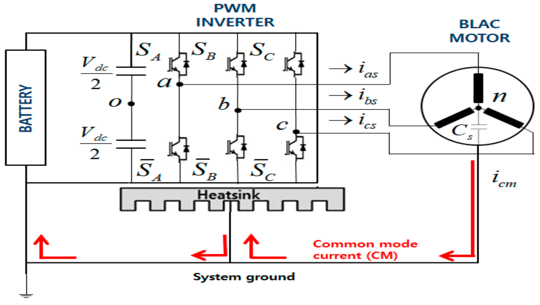
The three-phase VSI-fed BLAC motor drive is shown in
Figure 1. In this system, the CMV is defined as the potential difference between the star point of the load and the center of the dc-link of the inverter. From the three-phase balance condition, the CMV can be calculated as follows [
15,
16,
17,
18,
19,
20]:
where V
ao, V
bo, and V
co are the pole voltages of the a, b, and c phases, respectively.
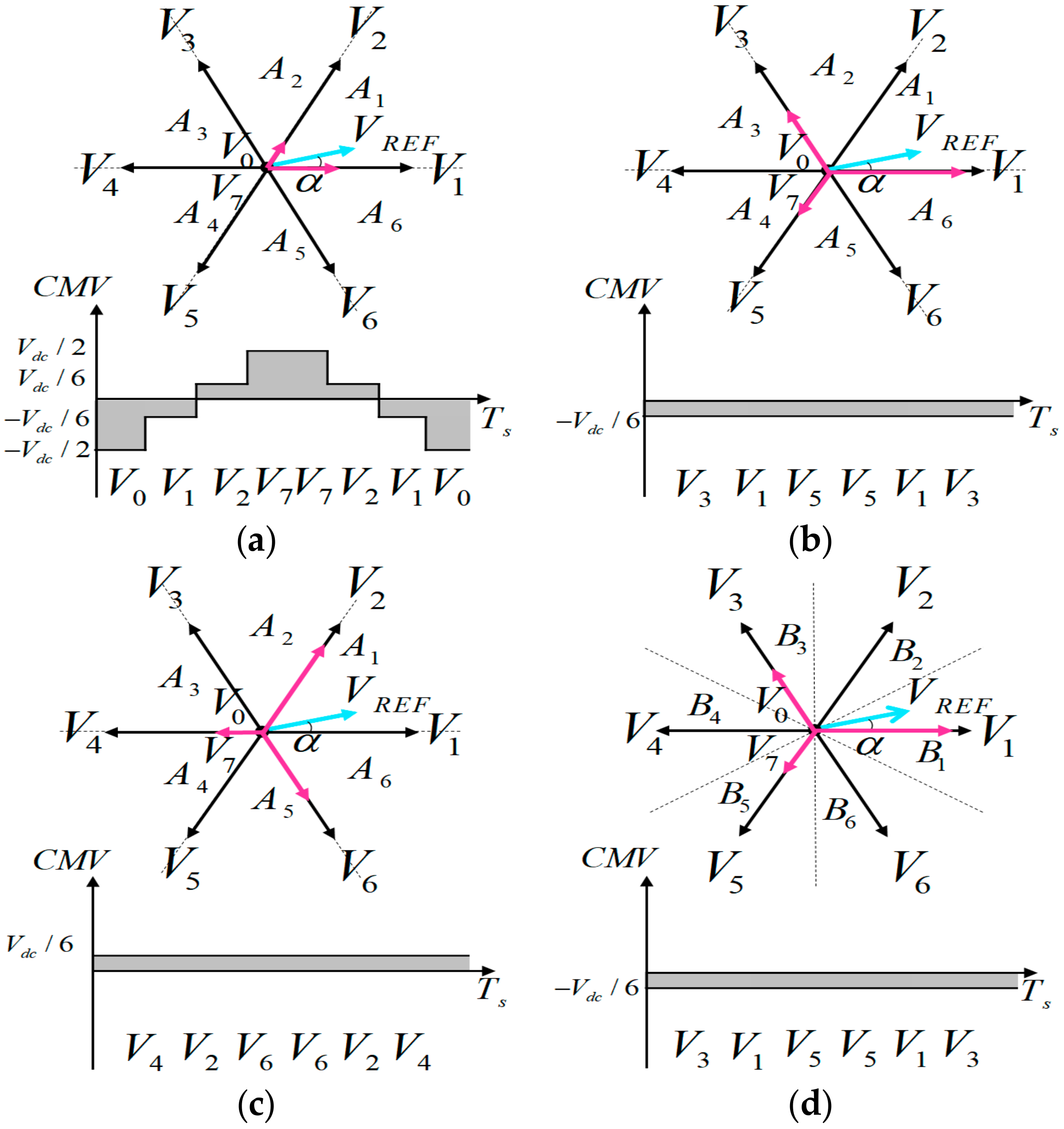
The three-phase VSI has eight switching states, and they can be expressed as voltage vectors in the d–q-plane. Among these voltage vectors, V0 and V7 are known as the zero voltage vectors, and the vectors from V1 to V6 are known as the active voltage vectors. The pulse patterns of SVPWMs for synthesizing the reference voltage vector are selected based on a specified performance criterion such as the minimum output voltage ripple, switching number, and more. In the space vector approach, the duty cycle of the voltage vectors are calculated according to the vector voltage-seconds balance rule.
On the other hand, the pulse patterns of SVPWMs are changed by sector in which reference voltage vector is located in the d–q-plane. In general, SVPWMs use A-type or B-type as sector classifiers. The A-type classifies d–q-plane into A
1–A
6 (starting from 0°, defined by an interval of 60°) as shown in
Figure 2a–c, and the B-type classifies d–q-plane into B
1–B
6 (starting from −30°, defined by an interval of every 60°) as shown in
Figure 2d.
Table 1 shows the CMV according to the voltage vectors. Note that the zero voltage vectors generate a large CMV (−V
dc/2 or +V
dc/2) and the active voltage vectors generate a small CMV (−V
dc/6 or +V
dc/6) [
15,
16,
17,
18,
19,
20].
The CSVPWM utilizes two active voltage vectors that are adjacent to the reference voltage vector and two zero voltage vectors to synthesize the reference voltage vector. Therefore, the peak value of CMV becomes ±V
dc/2. The formation of voltage vectors in sector A
1 (0° ≤ α < 60°) and corresponding CMV are shown in
Figure 2a. The pulse patterns for all sectors are listed in
Table 2.
However, the RSPWMs utilize three active voltage vectors that are 120
o apart from each other (remote-state vectors) to synthesize the reference voltage vector. There are two types of pulse patterns, yielding a total of six pulse patterns: (1) the odd pulse patterns consist of three odd active voltage vectors, i.e., V
1V
3V
5V
5V
3V
1, V
1V
5V
3V
3V
5V
1, and V
3V
1V
5V
5V
1V
3, and (2) the even pulse patterns consist of three even active voltage vectors, i.e., V
2V
4V
6V
6V
4V
2, V
2V
6V
4V
4V
6V
2, and V
4V
2V
6V
6V
2V
4. During switching period, the odd pulse patterns generate constant CMV of −V
dc/6, and even pulse patterns generate constant CMV of +V
dc/6. The RSPWM1 utilizes only one pulse pattern. One of the six pulse patterns for all sectors is listed in
Table 2 and its formation of voltage vectors in sector A
1 and corresponding CMV are shown in
Figure 2b. The RSPWM2 utilizes only one type of pulse pattern, i.e., the odd pulse patterns or the even pulse patterns. The RSPWM2A utilizes odd pulse patterns and the RSPWM2B utilizes even pulse patterns. Their pulse patterns for all sectors are listed in
Table 2. The formations of voltage vectors in sector A
1 and corresponding CMVs are shown in
Figure 2b,c, respectively. The RSPWM3 utilizes all six pulse patterns as listed in
Table 2. Its formation of voltage vectors in sector B
1 (−30° ≤ α < 30°) and corresponding CMV is shown in
Figure 2d. As listed in
Table 2, the pulse patterns for all sectors of RSPWMs are different. Thus, the overall performances and characteristics over a fundamental cycle are different for each sector [
19,
20], when compared with the CSVPWM that was sufficiently studied. However, all RSPWMs reduce the peak value of the CMV to ±V
dc/6, corresponding to a third of that of CSVPWM. Moreover, the CMVs are maintained at a constant value during 60° (RSPWM3) or 360° (RSPWM1, RSPWM2A, RSPWM2B).
Utilizing the pulse patterns of RSPWMs defined above, the PWM period equation and the complex variable voltage-seconds balance equation for RSPWMs can be written in a generalized form as follows:
where V
i is voltage vector, T
i is applied time of voltage vector, T
s is switching period, and V
REF is amplitude of reference voltage vector. Normalizing the voltage vector on-time values with 2V
dc/3, and using (2) and (3), applied time of voltage vectors for the two types of pulse patterns can be calculated as follows:
where α is the angle of V
REF, and the modulation index M
i (voltage utilization level) is defined as follows:
where V
s1, 6-step = 2V
dc/π, V
s1 is the magnitude of the fundamental component of V
REF and V
dc is the input dc voltage of inverter.
3. Analysis of Torque and Current Ripple
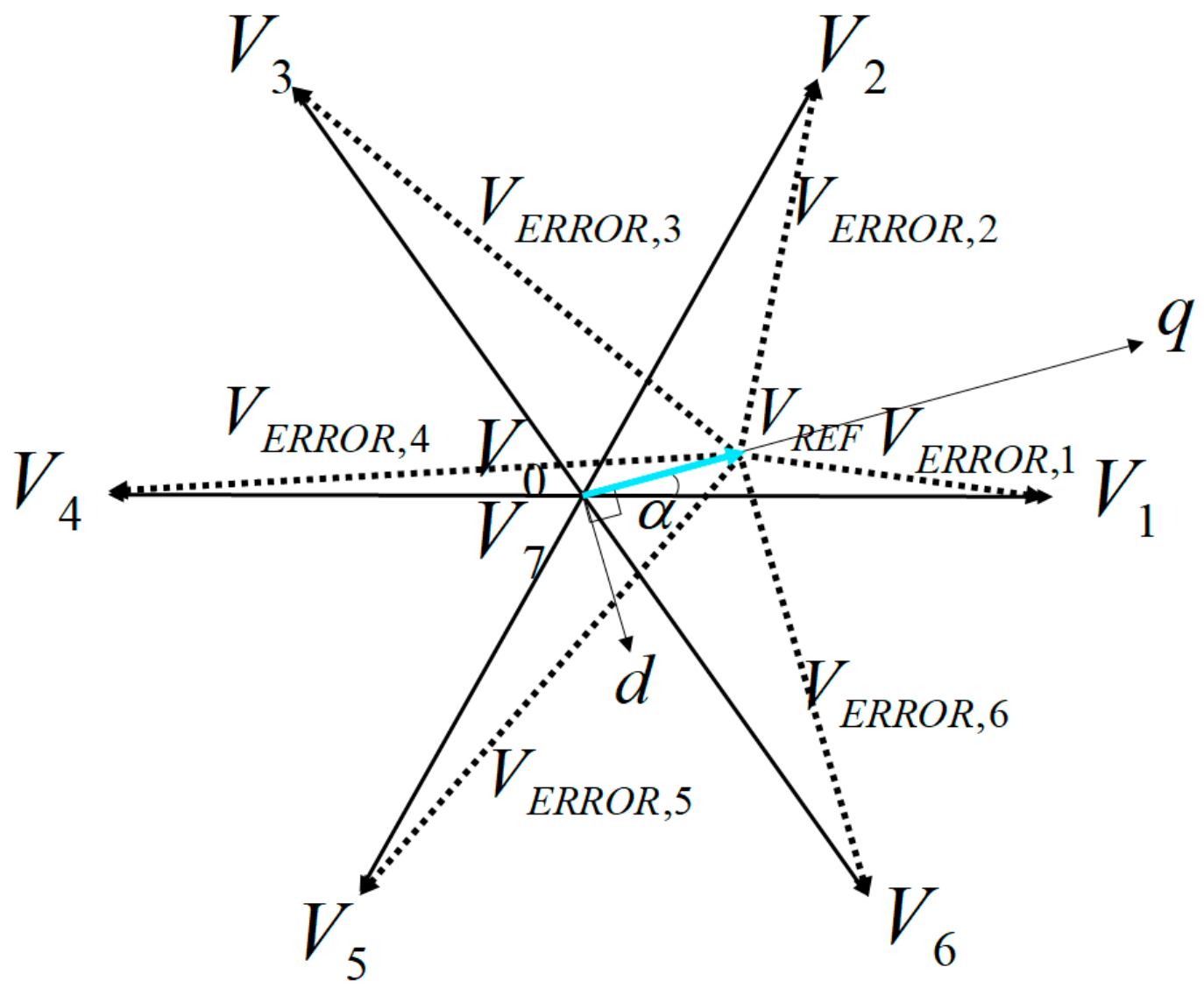
As described in the previous section, RSPWM has a total of six pulse patterns. They can synthesize the same reference voltage vector, on average. However, there is an instantaneous error voltage vector between the reference voltage vector and applied active voltage vector. Thus, error voltage vectors generated by each pulse pattern over a subcycle are different from each other. For a given reference voltage vector as an example, the error voltage vectors corresponding to the six active voltage vectors are as illustrated in
Figure 3, and can be expressed as follows:
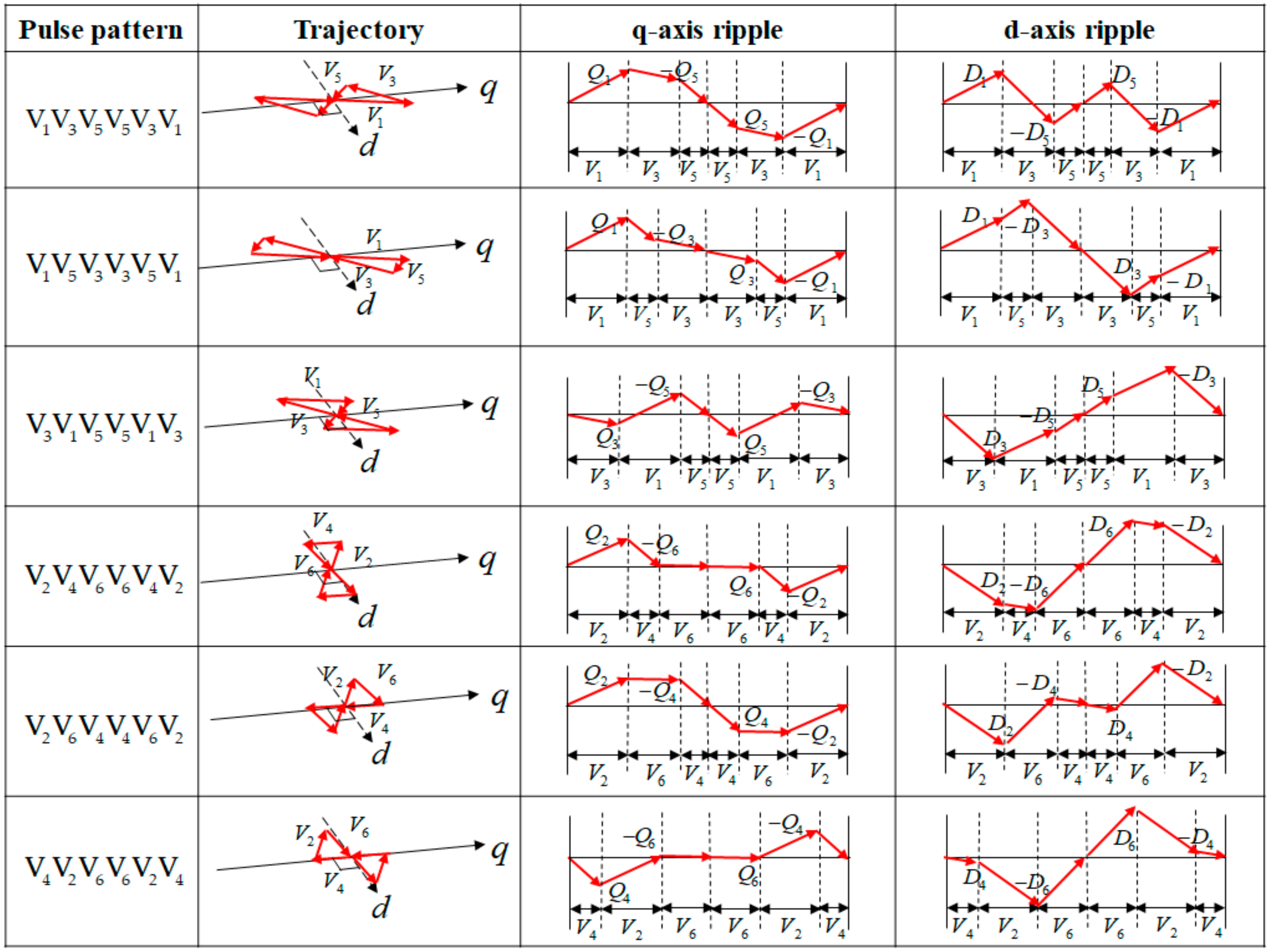
Since the error voltage vector sees the motor as its total leakage inductance, the current ripple vector is proportional to the time integral of the error voltage vector. The current ripple vector can be decomposed into d–q-axes current ripple vectors. When the q-axis is the reference axis of a synchronously revolving reference frame and the reference voltage vector is aligned with the q-axis as shown in
Figure 3, the trajectory of the error vectors and corresponding d–q-axes current ripple vectors of six pulse patterns of RSPWM are illustrated in
Figure 4, where the quantities Q
1–Q
6 and D
1–D
6 are as defined in (8) and (9). These values are products of a component of the error voltage vector corresponding to the applied active voltage vector and its applied time [
3,
4,
5,
6,
7,
8].
where V
dc is the input dc voltage of inverter, M
i is the modulation index, α is the angle of V
REF, l is the total leakage inductance of the motor, and T
1–T
6 are the dwell times of V
1–V
6. From the equations, it is observed that the direction of error voltage vector determines the slope of the current ripple trajectory, and the dwell time of the active voltage vector determines the magnitude of the current ripple.
3.1. RMS Torque Ripple
Under the assumptions that the eddy currents and hysteresis losses are negligible and the iron core of the BLAC motor is unsaturated, the stator d–q-axes voltage equation of the BLAC motor in the synchronous rotating reference frame can be expressed as follows:
where λ
d = L
di
d + λ
PM and λ
q = L
qi
q are the total flux linkages along the d–q-axes, respectively, λ
PM is the permanent magnet flux linkage, ω
r is the mechanical angular speed, u
d and u
q are the stator voltages along the d–q-axes, respectively, i
d and i
q are the stator currents along the d–q-axes, respectively, L
d and L
q are the stator inductances along the d–q-axes, respectively, and R is the stator resistance. In case the rotor of the BLAC motor is surface-mounted, L
d and L
q are equal. Since the reference voltage vector is aligned with the q-axis as shown in
Figure 3, the PM flux exists only along the d-axis. Hence, the torque ripple content is generated by interaction between the PM flux and the q-axis current ripple while the d-axis current ripple is responsible for the ripple in the flux linkage in the air gap. The instantaneous torque ripple can be expressed as follows [
6,
7,
8]:
where K
T is the torque coefficient, P is the number of pole pairs,
and
are the current ripples along the d–q-axes. According to (11), the torque ripple can be seen to be directly proportional to the q-axis current ripple. The RMS torque ripple and the RMS q-axis current ripple over a subcycle can be expressed as follows [
6,
7,
8]:
Thus, the RMS q-axis current ripples over a subcycle of six pulse patterns of RSPWM in
Figure 4 can be calculated using (8), (9), and (13) as follows:
Thus, the RMS torque ripples over a subcycle of six pulse patterns of RSPWM can be obtained using (12) and (14).
3.2. RMS Current Ripple
Similarly, the RMS
d-axis current ripple over a subcycle can be expressed as follows [
3,
4,
5]:
and the RMS d-axis current ripples over a subcycle of six pulse patterns of RSPWM in
Figure 4 can be calculated using (8), (9), and (15) as follows:
Additionally, the RMS current ripple over a subcycle can be calculated as follows:
Thus, using (14), (16), and (17), the rms current ripple over a subcycle of six pulse patterns of RSPWM can be obtained. From the equations, it can be observed that the values of the RMS torque ripple and the RMS current ripple are proportional to the (18a) and (18b), respectively.
Hence, being independent of input dc voltage, switching frequency, and machine parameters, the RMS torque ripple and the RMS current ripple can be normalized with respect to (18a) and (18b), respectively [
6,
7,
8].
4. Minimum rms Torque Ripple-RSPWM
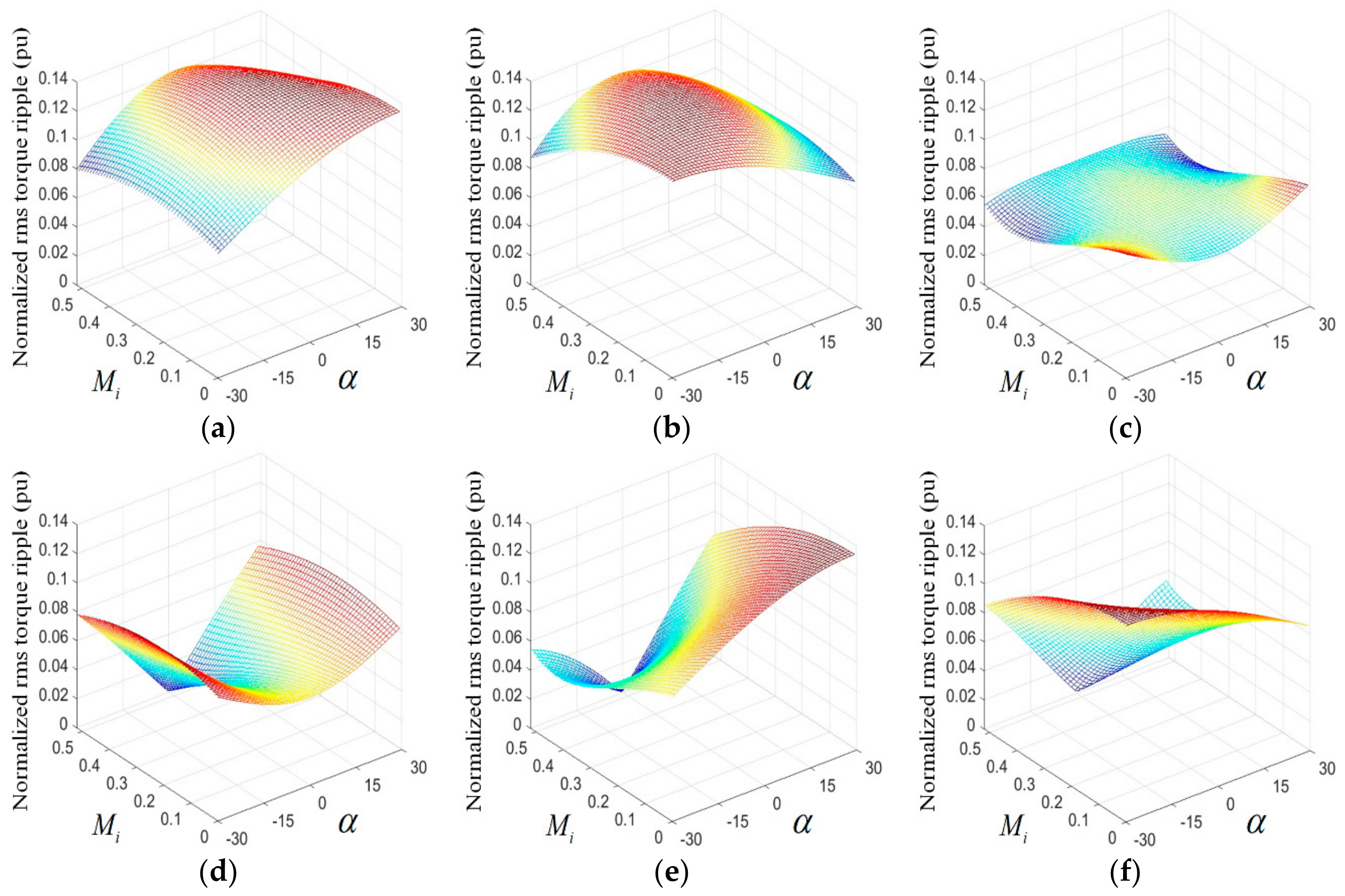
As described in the previous section, error voltage vectors generated by a pulse pattern determine d–q-axes current ripples, where only the q-axis current ripple is related to the RMS torque ripple. On the other hand, the angle of the reference voltage vector α changes with every subcycle, and the magnitude of the reference voltage vector VREF also changes during variable speed control. Thus, the RMS torque ripple and the RMS current ripple also change every subcycle according to α and Mi (∝VREF). Hence, the RMS torque ripple and the RMS current ripple of the six pulse patterns of RSPWM need to be calculated and analyzed under all ranges of the reference voltage vector (α and Mi).
Figure 5 shows the analytical results of the RMS torque ripple over a subcycle of six pulse patterns of RSPWM under sector B
1 (−30° ≤ α < 30°) and 0 ≤ M
i < 0.52, that is, the modulation index range of the RSPWM. The RMS torque ripple is calculated using (12)–(14) and normalized by (18a). From
Figure 5, it is confirmed that the RMS torque ripple depends on α and M
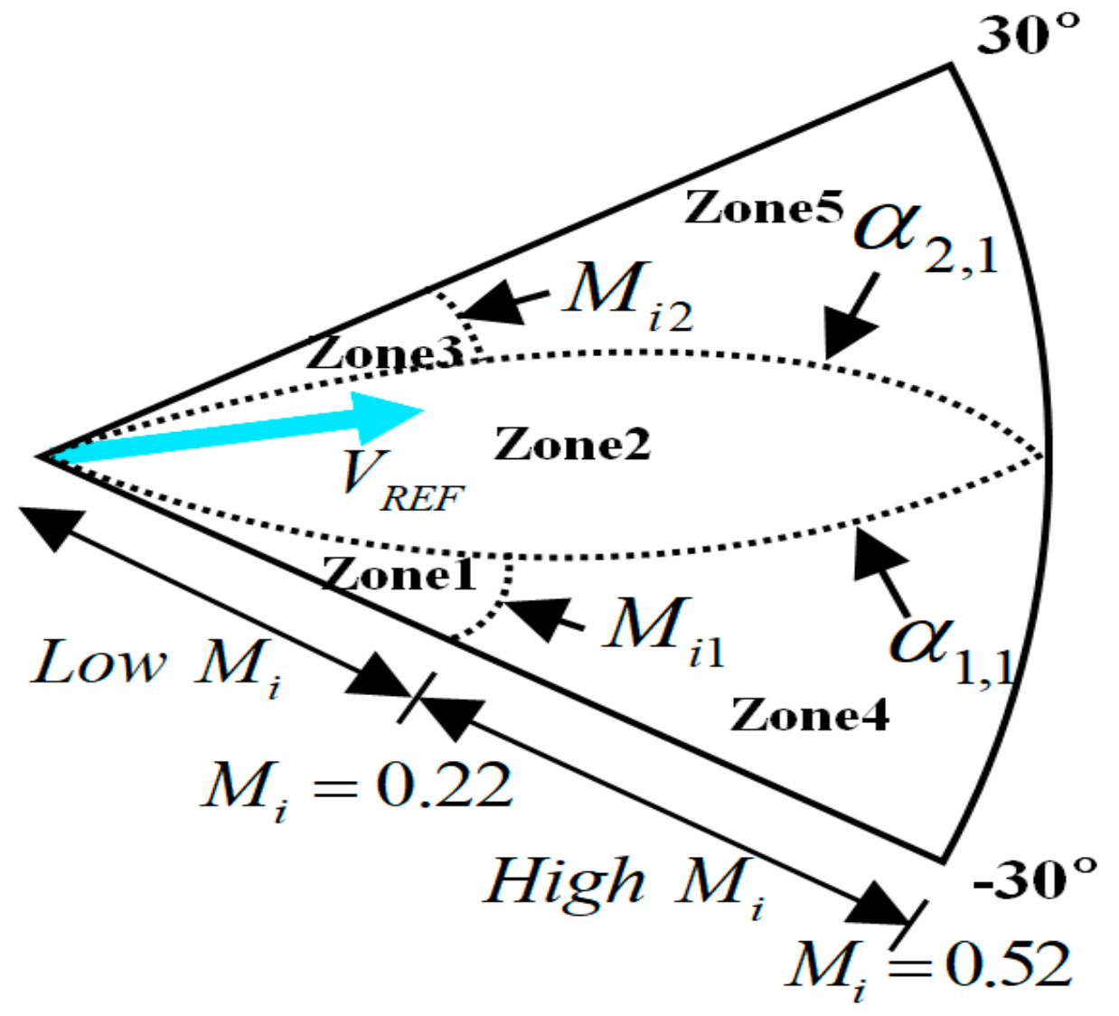
i, and each pulse pattern has its own RMS torque ripple characteristics. Additionally, it is observed that the pulse pattern with the lowest RMS torque ripple varies with α and M
i in a sector. The comparison shows that the RMS torque ripple corresponding to pulse pattern V
3V
1V
5V
5V
1V
3 is the lowest when the reference voltage vector is in Zone 1 and Zone 3 as shown in
Figure 6, where α
1,1 and α
2,1 are boundary values of α in the sector B
1, and M
i1 and M
i2 are boundary values of M
i. The M
i can also be defined as low M
i when M
i ≤ 0.22 or high M
i when M
i > 0.22. Note that Zones 1 and 3, and Zones 4 and 5 are symmetric around the middle of the sector (i.e., α = 0°). Pulse pattern V
2V
4V
6V
6V
4V
2, V
2V
6V
4V
4V
6V
2 and V
4V
2V
6V
6V
2V
4 are best in terms of the RMS torque ripple in Zone 2, Zone 4, and Zone 5, respectively, in
Figure 6.
In this way, pulse patterns with zones for sector B
2–B
6 can be obtained, listed in
Table 3. Therefore, the proposed RSPWM technique, referred to as MTR-RSPWM, divides each sector into five zones, as shown in
Figure 6, and employs pulse patterns with the lowest RMS torque ripple within each zone.
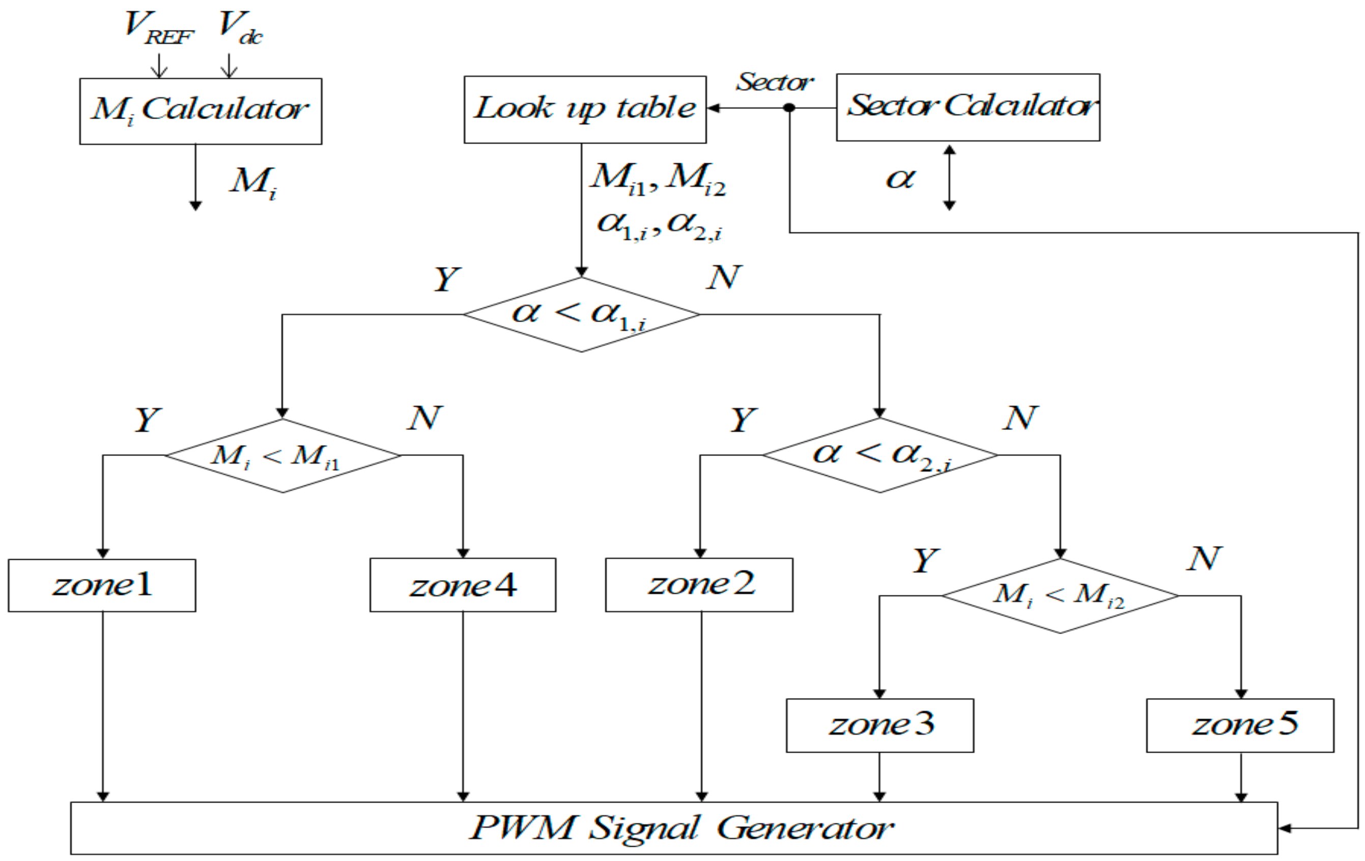
Figure 7 shows a block diagram of the MTR-RSPWM. The look-up table obtained from analytical results receives sector information from sector calculator and outputs the boundary values of α (α
1,i and α
2,i) and M
i (M
i1 and M
i2) corresponding to each sector. After comparing current α and M
i with the boundary values, the zone is determined, and the corresponding pulse pattern is generated by PWM signal generator. The α
1,i and α
2,i can be obtained as follows:
where α
1,1 and α
2,1 are the boundary values of α
1 and α
2 in sector B
1, respectively, and i is the number of sector. M
i1 and M
i2 for all sectors are same.
On the other hand, the RMS current ripple over a subcycle is also calculated and analyzed. It is observed that the RMS current ripple, which corresponds to a single pulse pattern, i.e., V
3V
1V
5V
5V
1V
3 is the lowest when the reference voltage vector is in sector B
1, for all range of α and M
i. Through further analysis of the other sectors, it is confirmed that obtained pulse patterns are the same as that of RSPWM3 introduced in [
19,
20]. Hence, the analytical results of normalized RMS current ripple over a subcycle for six pulse patterns are not included in this paper.
From the analysis of six pulse patterns of RSPWM in terms of the RMS torque ripple and RMS current ripple, it is confirmed that minimum RMS torque ripple can be obtained by MTR-RSPWM and minimum RMS current ripple can be obtained by RSPWM3.
5. Results and Discussion
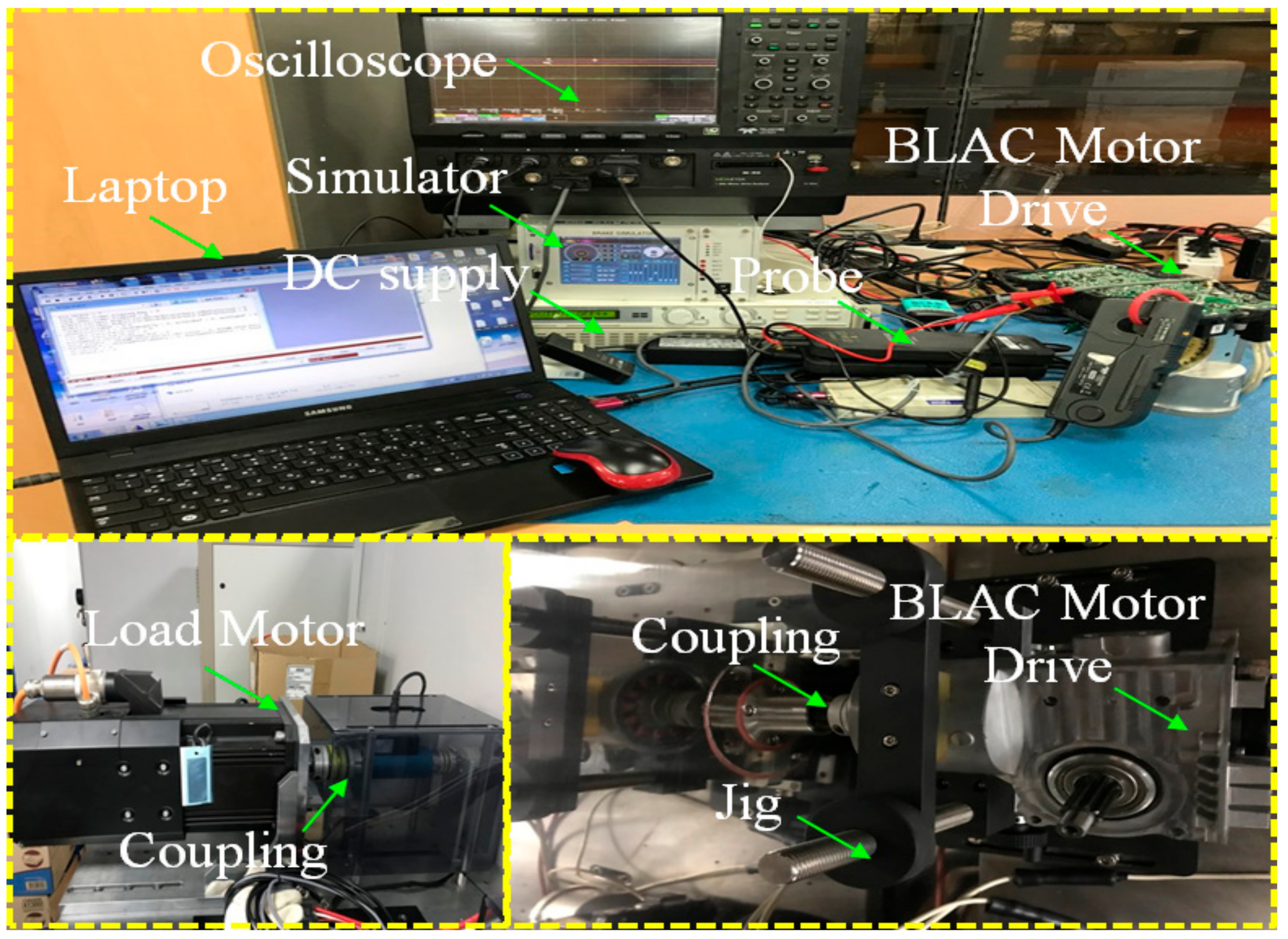
In this section, the analytical, simulation, and experimental results are presented. The analysis and simulation was carried out using MATLAB-R2015b and PSIM-9.0. The experimental setup, based on MCU (TRICORE277, INFINEON), is shown in
Figure 8.
The system parameters are listed in
Table 4. The test was performed at 500 RPM with T
L = 0.44 N·m, corresponding to M
i = 0.2. The experimental waveforms were obtained using an oscilloscope (MDA810A, LECROY) and torque performance tester (ADCSYSTEM).
In the previous section, the RMS torque ripple and current ripple over a subcycle are calculated for six pulse pattern of RSPWM. These quantities can be averaged over a fundamental cycle to obtain the respective RMS values, as follows [
3,
4,
5,
6,
7,
8]:
The RMS current ripple and torque ripple over a fundamental cycle by the MTR-RSPWM is evaluated and compared against those of the RSPWM3, which generates minimum RMS current ripple.
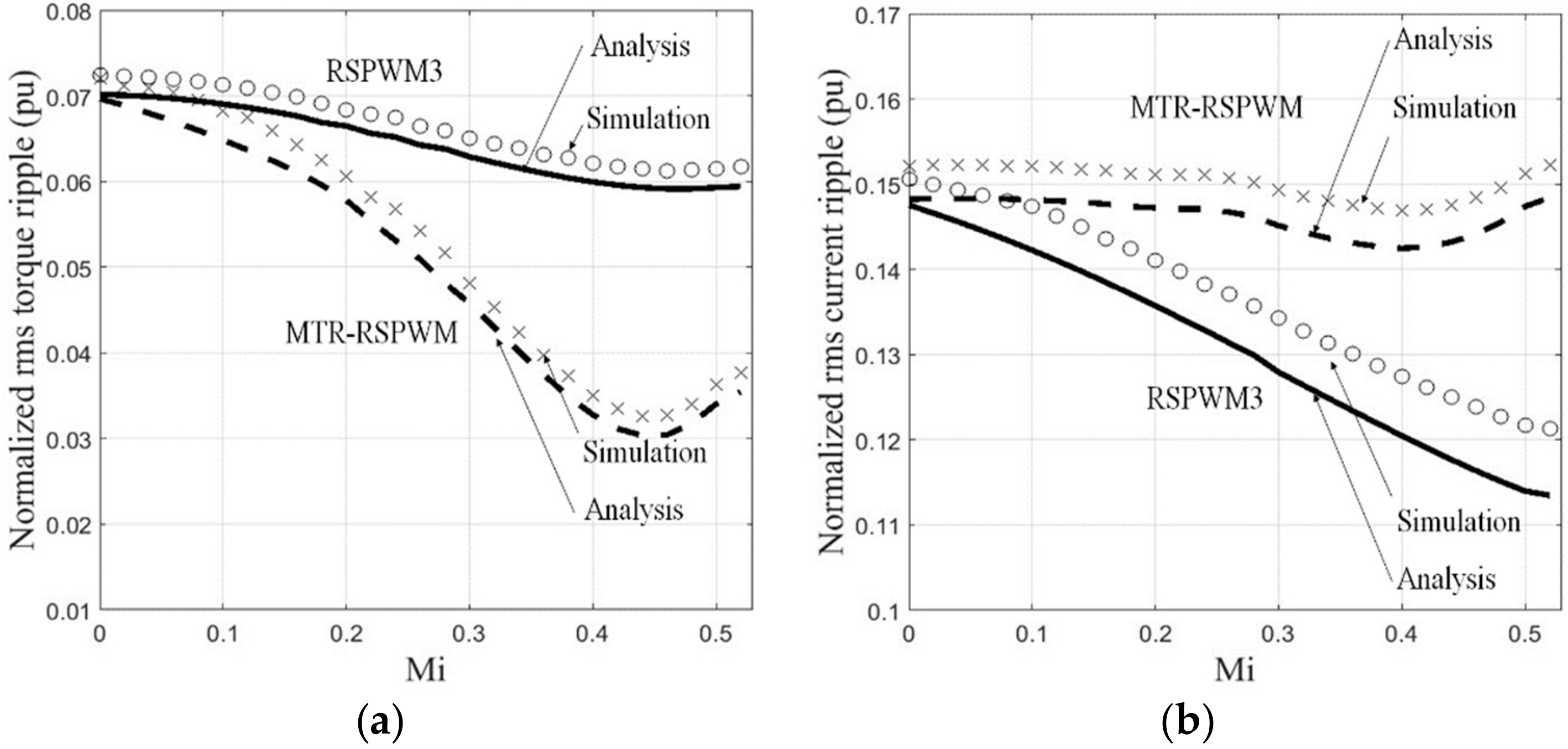
Figure 9a,b shows the analytical and simulation results of the normalized RMS torque ripple and current ripple over a fundamental cycle corresponding to the RSPWM3 and MTR-RSPWM for M
i ranging from 0 to 0.52 in steps of 0.02. It can be observed that the analytical and simulation results agree well in both the RMS torque ripple and current ripple. The MTR-RSPWM reduces RMS torque ripple compared to the RSPWM3 over the entire range of modulation index, as shown in
Figure 9a. The optimum reduction is observed at M
i = 0.44, where the RMS torque ripple is reduced by approximately 50%. On the other hand, MTR-RSPWM increases RMS current ripple compared to RSPWM3 over the entire range of modulation index, as shown in
Figure 9b. This phenomenon occurs because the reduction of q-axis current ripple resulted in an increase of d-axis current ripple and the change of d-axis current ripple is greater than that of the q-axis current ripple.
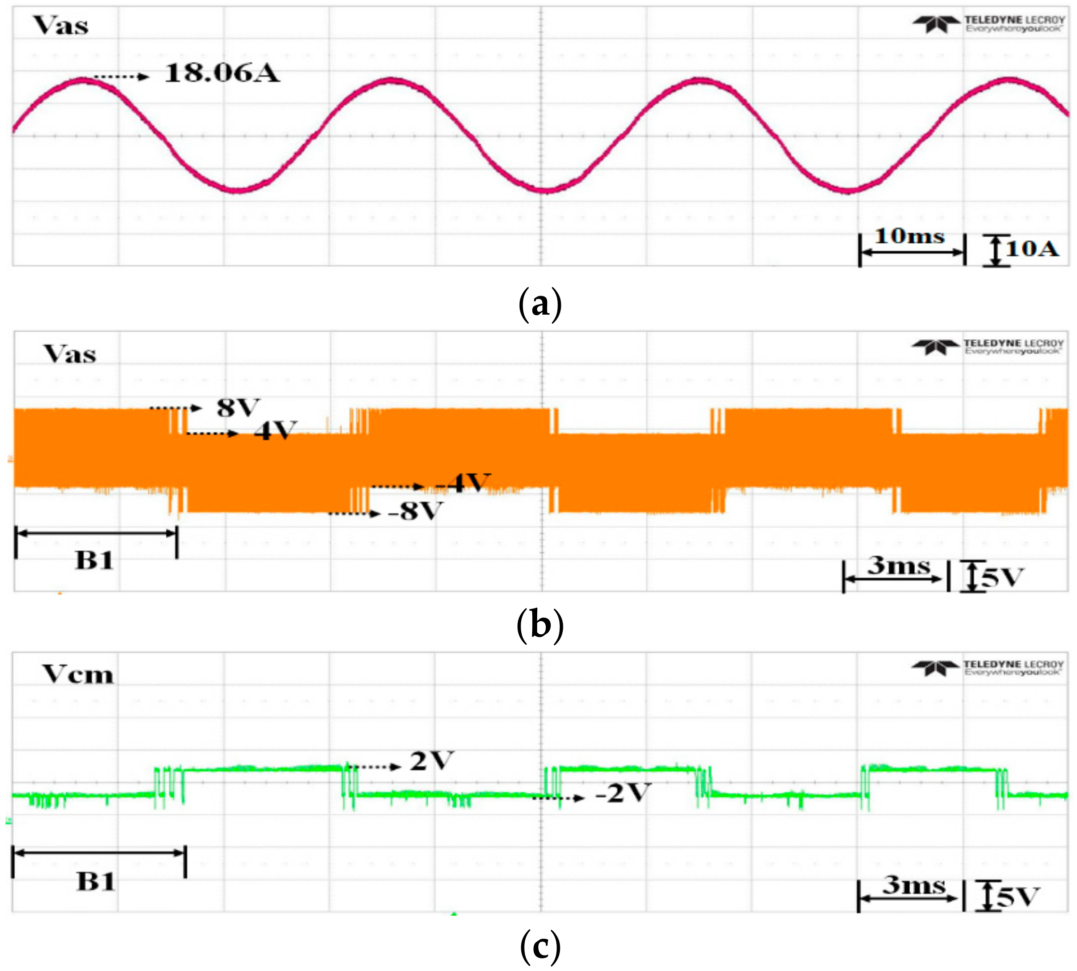
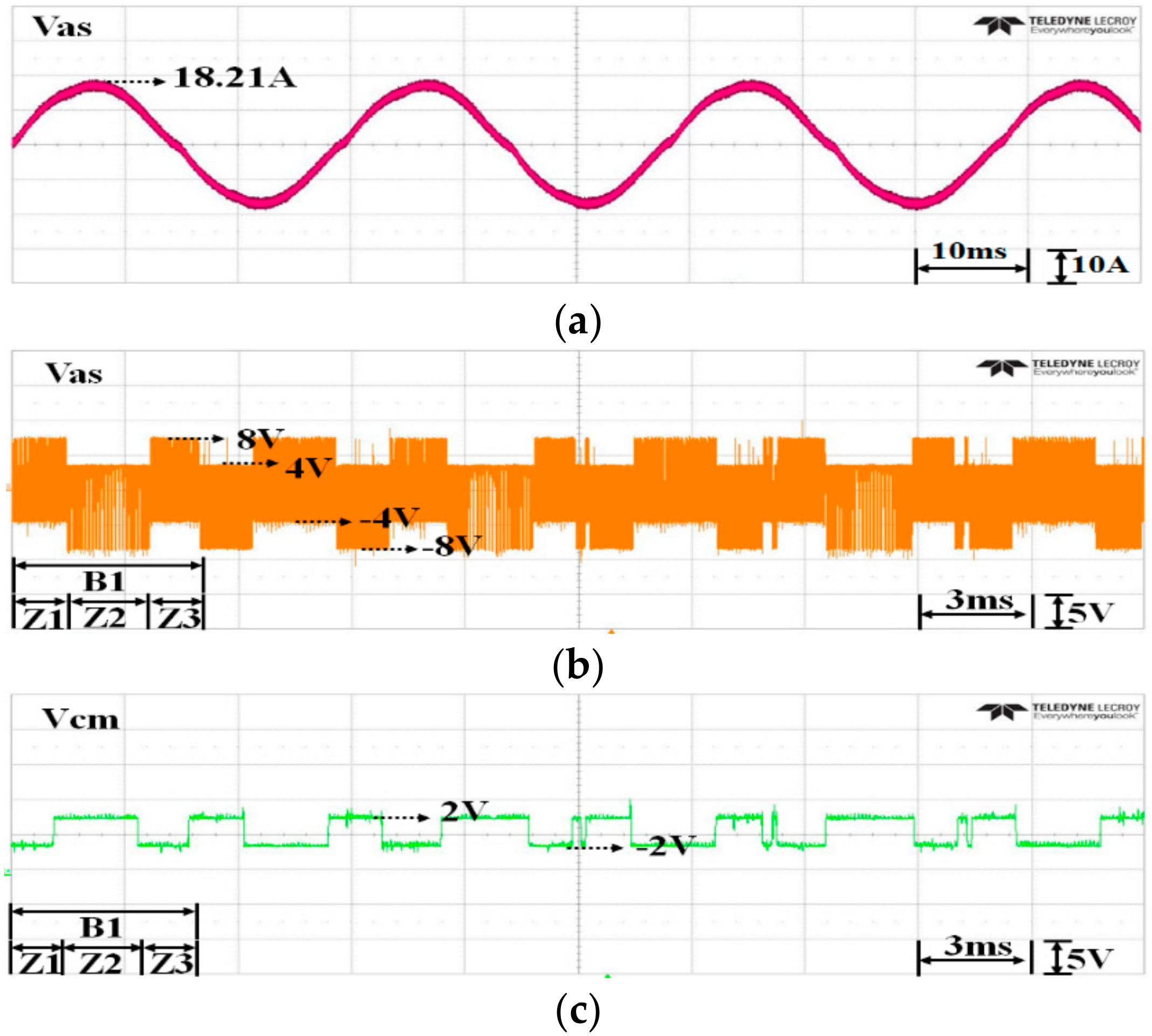
Figure 10a and
Figure 11a show the experimental waveforms of the phase-a current obtained by RSPWM3 and MTR-RSPWM, respectively. It is shown that for the MTR-RSPWM, the output current ripple is slightly higher than that of RSPWM3 as expected. The RMS current ripple values over a fundamental cycle according to M
i, of the RSPWM3 and the MTR-RSPWM are analyzed again later with the RMS torque ripple values.
Figure 10b and
Figure 11b show the experimental waveforms of the phase-a voltage obtained by RSPWM3 and MTR-RSPWM, respectively. For the phase-a voltage, odd pulse patterns generate +2V
dc/3 (V
1) and −V
dc/3 (V
3 and V
5), and even pulse patterns generate +V
dc/3 (V
2 and V
6) and −2V
dc/3 (V
4). Because RSPWM3 employs only one pulse pattern per sector as listed in
Table 2, the values of phase voltage are fixed over a sector. On the other hand, the pulse pattern for the MTR-RSPWM is changed by the zone within a sector. The type of pulse pattern is changed from odd to even and even to odd in the odd sector (vice versa in the even sector) when the reference voltage vector crosses Zone 1, Zone 2, and Zone 3 at low M
i as shown in
Figure 6. Thus, the values of phase voltage are also changed by the type of pulse pattern. However, in this case, the reference voltage vector crosses Zone 4, Zone 2, and Zone 5 at high M
i in
Figure 6, because the types of pulse patterns according to the zones are same, the values of phase voltage are fixed over a sector as in RSPWM3.
Figure 10c and
Figure 11c show the experimental waveforms of the CMV obtained by the RSPWM3 and the MTR-RSPWM, respectively. The CMV also depends on the type of pulse pattern along with the phase voltage. As explained in
Section 2, odd pulse patterns generate a constant CMV of −V
dc/6, and even pulse patterns generate constant CMV of +V
dc/6. At low M
i, while the CMV of RSPWM3 is fixed over a sector, the CMV of MTR-RSPWM changes its polarity twice over a sector, as shown in
Figure 10c and
Figure 11c. However, the peak value of CMV is still maintained at ±V
dc/6. Furthermore, at high M
i, the CMV of MTR-RSPWM is fixed over a sector, as it is in RSPWM3.
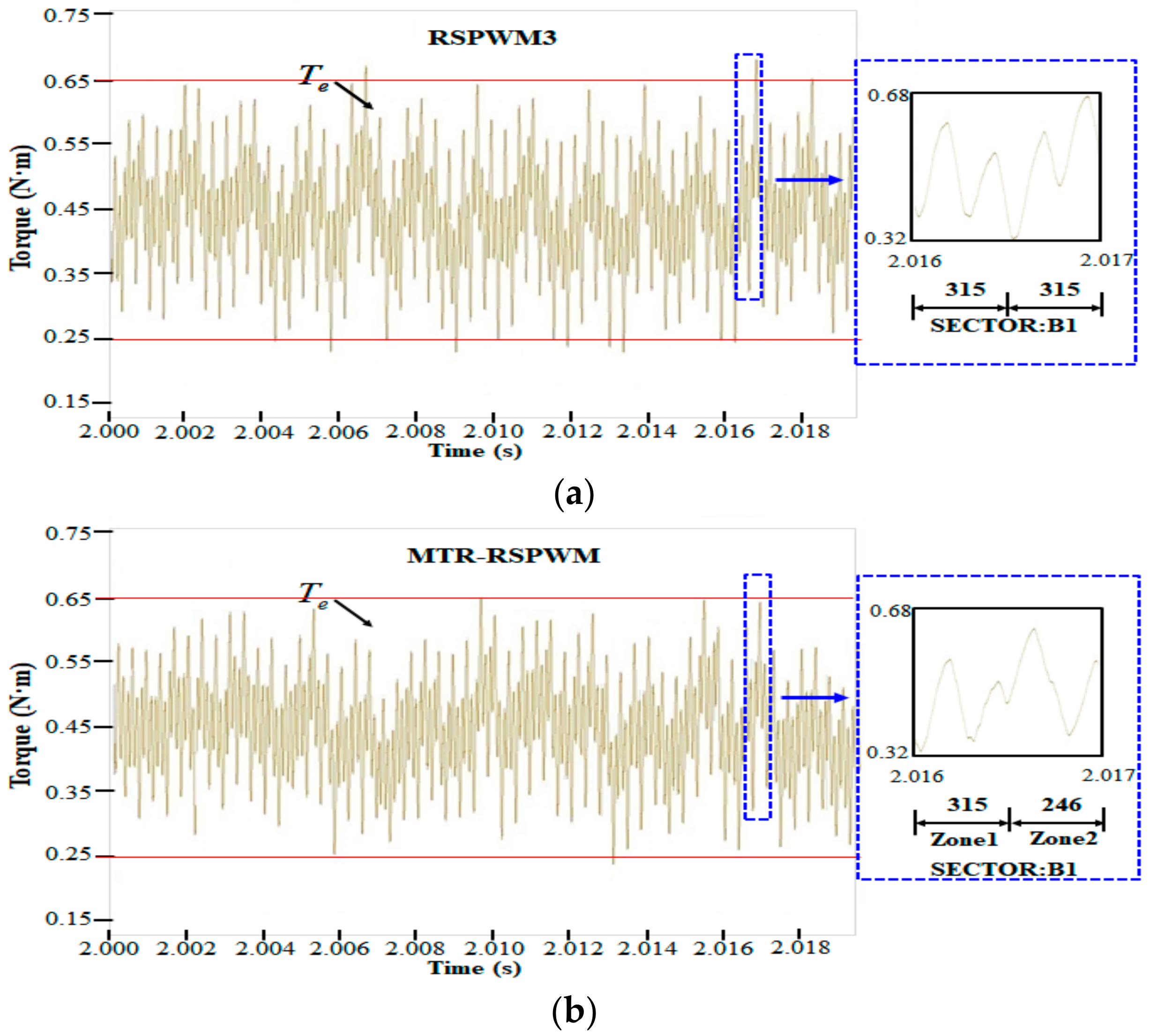
Figure 12a,b show the experimental waveforms of the output torque obtained by the RSPWM3 and the MTR-RSPWM, respectively. In the figures, the right traces are zoomed portions of the left traces when the zone is changed, where it is observed that the torque ripple closely resembles that of the q-axis current ripple shown in
Figure 4. The RMS torque ripple values, over a fundamental cycle according to M
i, of the RSPWM3 and the MTR-RSPWM are shown in
Figure 13a.
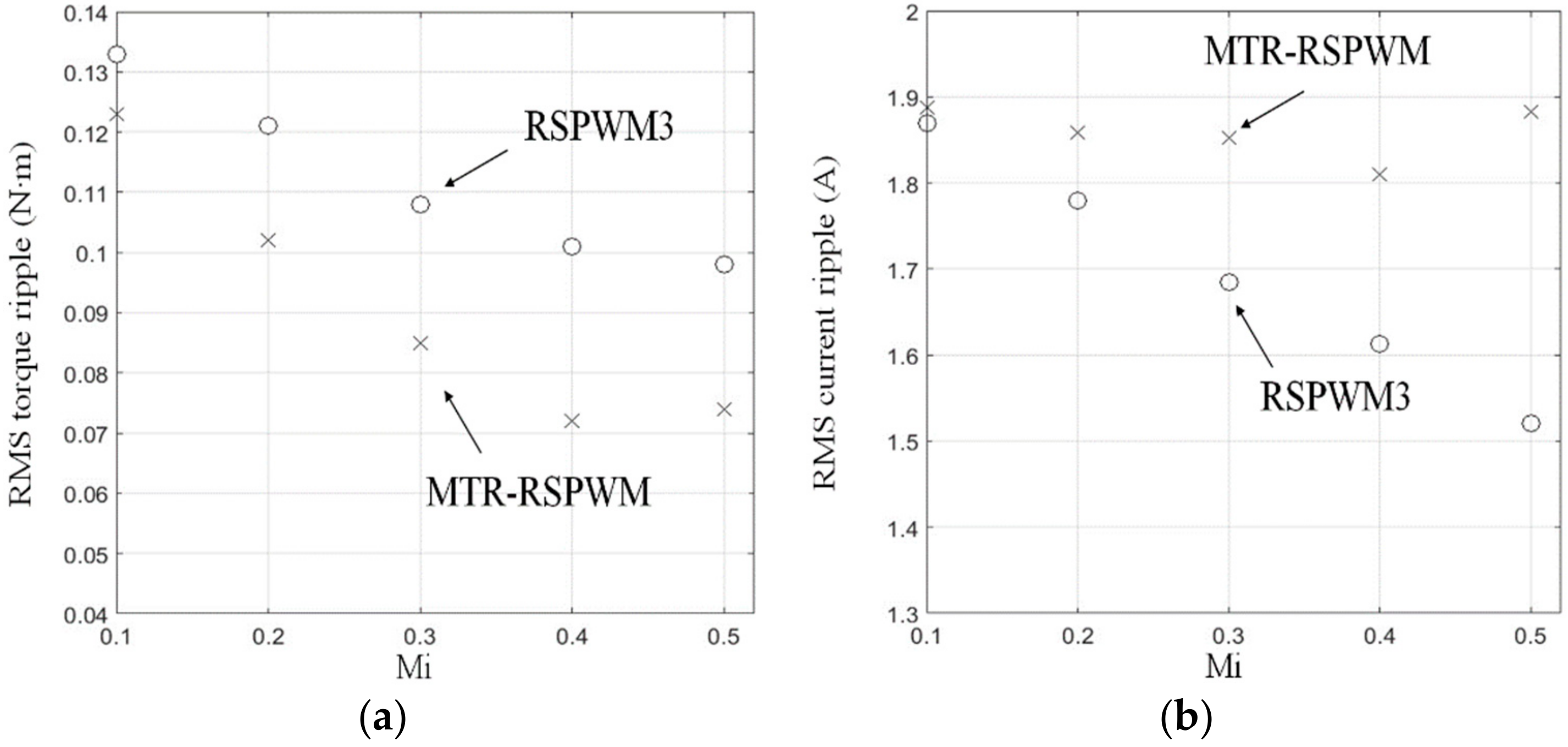
Figure 13 shows the RMS torque ripple and RMS current ripple obtained experimentally for M
i ranging from 0.1 to 0.5 in steps of 0.1. To get the instantaneous ripple, the average value is subtracted from the instantaneous value, and then the RMS values are calculated over a fundamental cycle.
Contrary to the analysis and simulation results, the experimental results are not normalized values but are practical values that include the factors (18a) and (18b), respectively. The optimum reduction is observed at Mi = 0.4, where the RMS torque ripple is reduced by approximately 30%. The experimental results include the effects of the device drops and dead times, the dependence of the machine parameters on frequency, depth of slots, and distortion in the distribution of magnetomotive force. Moreover, the ripple generated by the coupling that connects the BLAC motor and the load motor is also included. These factors may lead to some distortion in the experimental results of the RMS torque ripple and RMS current ripple, which in turn may result in some difference between the per cent reductions of analytical, simulation, and experimental results. Nevertheless, all these three sets of results demonstrate similar tendencies and are consistent in proving a significant reduction in the RMS torque ripple by MTR-RSPWM.


