Development of Real-Time Implementation of a Wind Power Generation System with Modular Multilevel Converters for Hardware in the Loop Simulation Using MATLAB/Simulink

Abstract
1. Introduction
2. Configuration of an MMC
3. Proposed Simulink Real-Time Model for the HILS Application
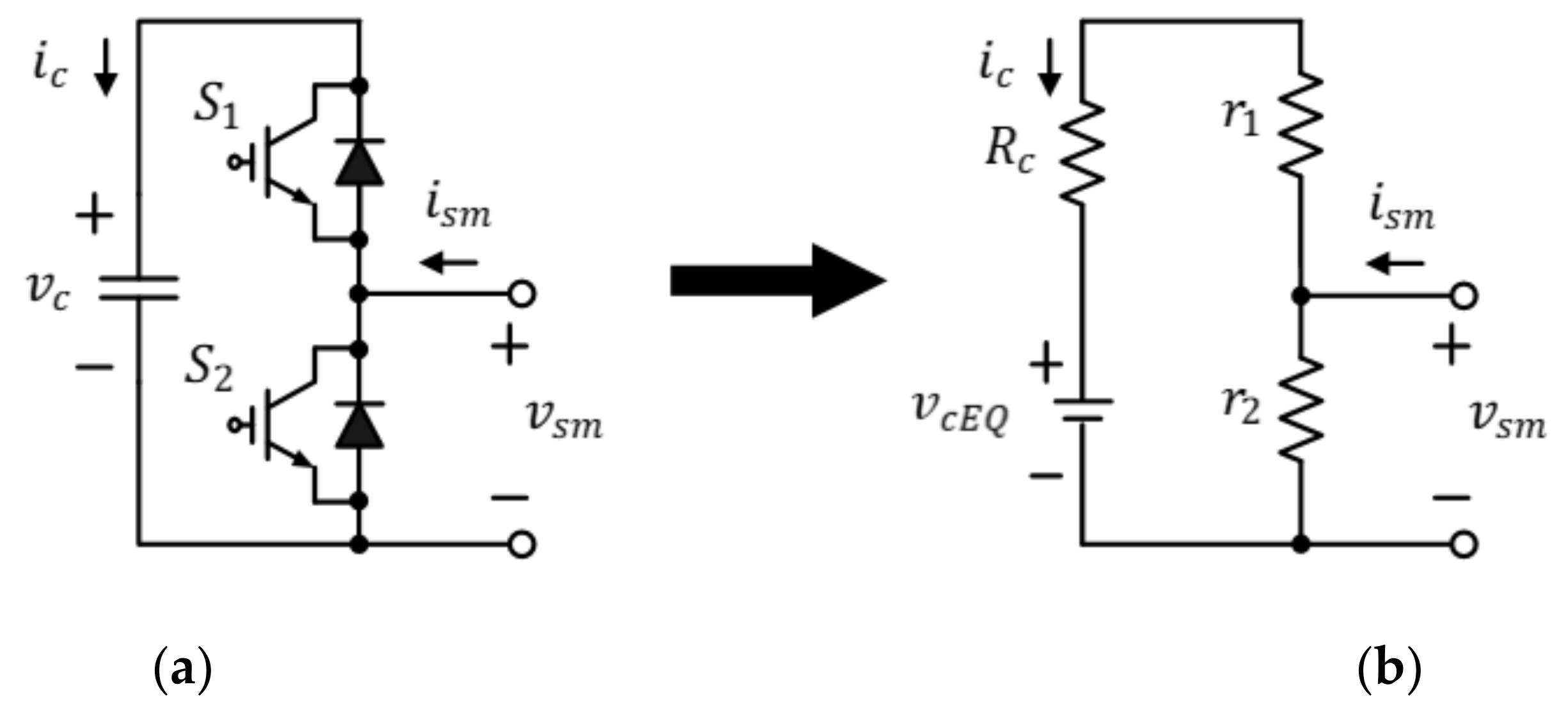
3.1. Detaild Equivalent Model (DEM) for the MMC
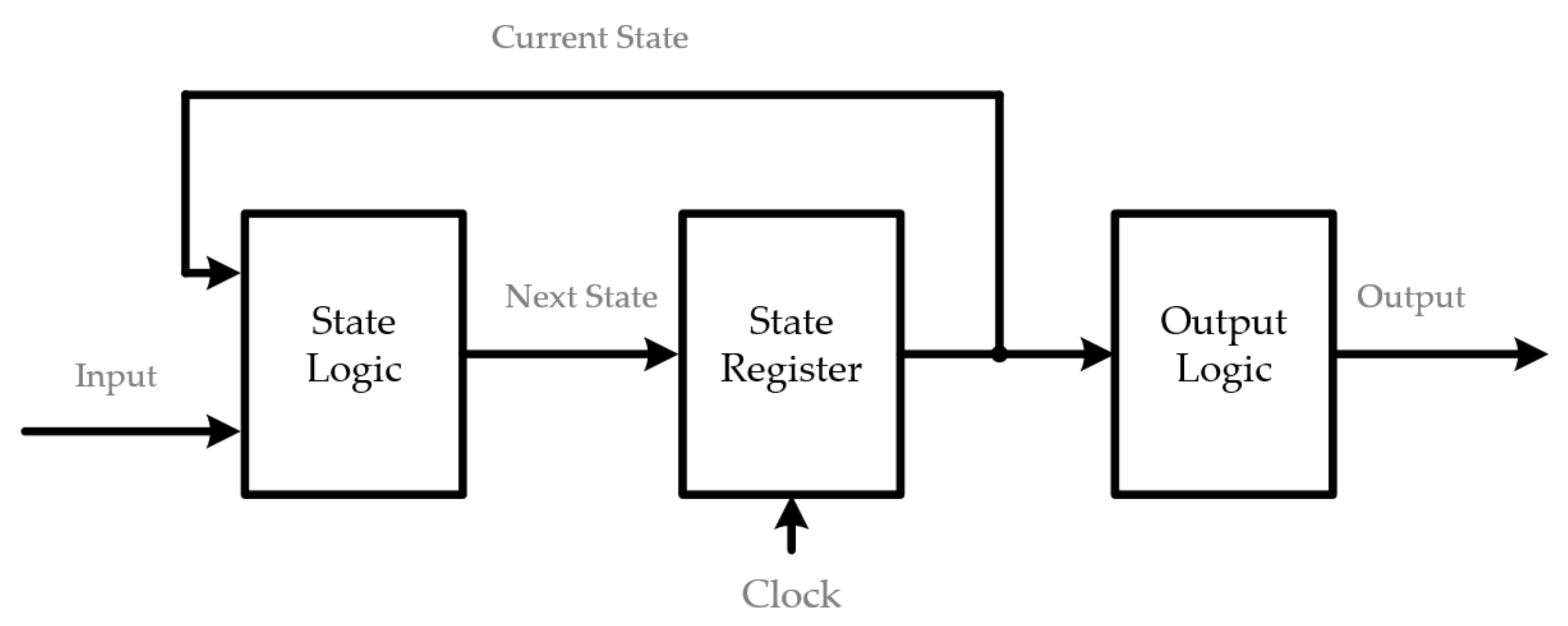
3.2. The Proposed DEM Implemented Using MATLAB/Simulink
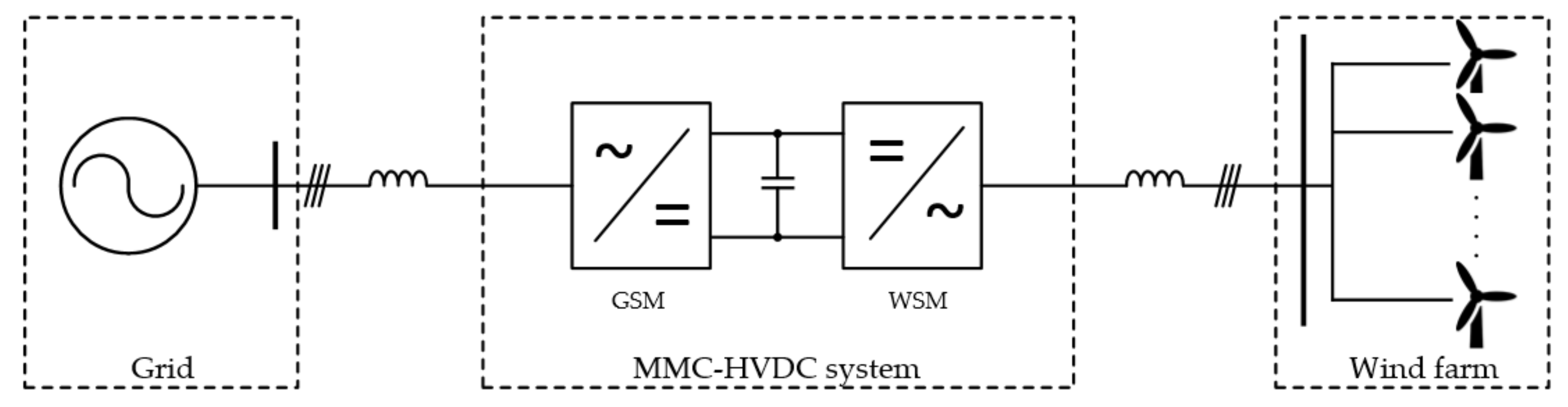
3.3. DFIG Wind Power Generation System Model
4. HILS Implementation
Voltage Controller of the MMC by the FPGA
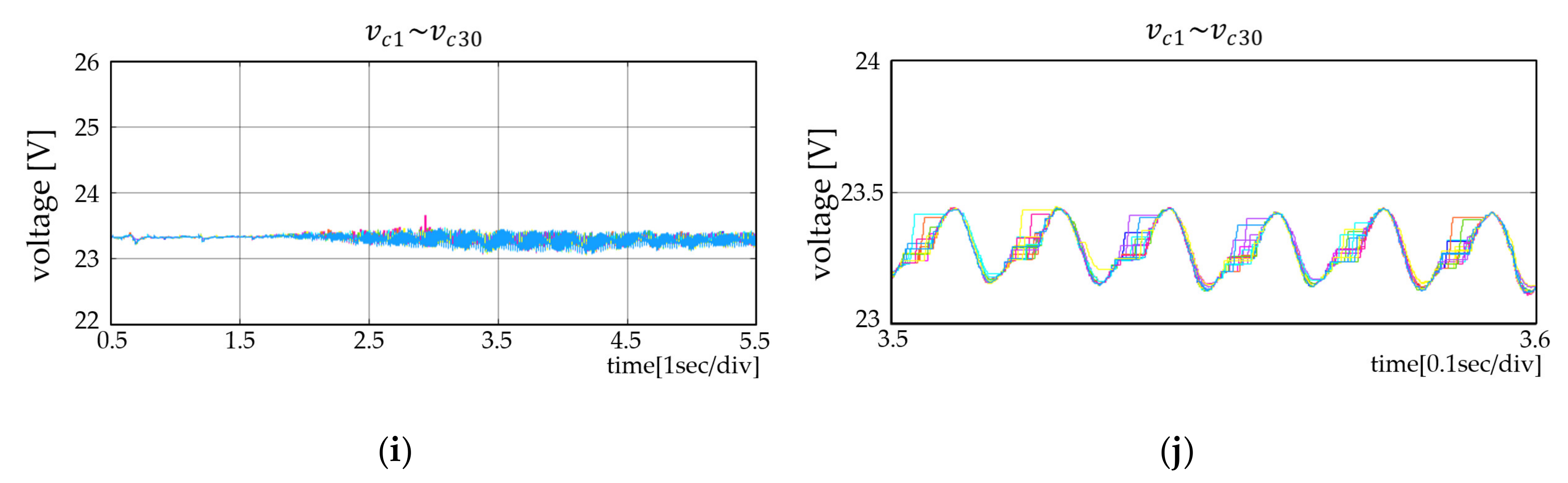
5. Experimental Results of the PC-Based Simulation and from the HILS
6. Conclusions
Author Contributions
Funding
Conflicts of Interest
References
- Chen, Z.; Blaabjerg, F. Wind farm—A power source in future power systems. Renew. Sustain. Energy Rev. 2009, 13, 1288–1300. [Google Scholar] [CrossRef]
- Markard, J.; Petersen, R. The offshore trend: Structural changes in the wind power sector. Energy Policy 2009, 37, 3545–3556. [Google Scholar] [CrossRef]
- Lu, M.-S.; Chang, C.-L.; Lee, W.-J.; Wang, L. Combining the wind power generation system with energy storage equipment. IEEE Trans. Ind. Appl. 2009, 6, 2109–2115. [Google Scholar]
- Park, J.; Lee, D. A new direct torque control scheme of an induction motor using duty ratio modulation. J. Elec. Eng. Tech. 2018, 13, 1223–1231. [Google Scholar]
- Meah, K.; Ula, S. Comparative evaluation of HVDC and HVAC transmission systems. Power Eng. Soc. Gen. Meet. 2007, 1–5. [Google Scholar] [CrossRef]
- Breuer, W.; Retzmann, D.; Uecker, K. Highly efficient solutions for smart and bulk power transmission of green energy. In Proceedings of the 21st World Energy Congress (WEC) 2010, Montreal, QC, Canada, 12–16 September 2010. [Google Scholar]
- Jiang, H.; Ekstrom, A. Multiterminal HVDC systems in urban areas of large cities. IEEE Trans. Power Delivery 1998, 13, 1278–1284. [Google Scholar] [CrossRef]
- Veilleux, E.; Ooi, B. Power flow analysis in multi-terminal HVDC grid. In Proceedings of the IEEE/PES Power Systems Conference and Expo, Phoenix, AZ, USA, 20–23 March 2011; pp. 1–7. [Google Scholar]
- Flourentzou, N.; Agelidis, V.; Demetriades, G. VSC-Based HVDC power transmission systems: An overview. IEEE Trans. Power Elect. 2009, 24, 592–602. [Google Scholar] [CrossRef]
- Wang, W.; Barnes, M. Power flow algorithms for multi-terminal VSC-HVDC with droop control. IEEE Trans. Power Syst. 2014, 29, 1721–1730. [Google Scholar] [CrossRef]
- Lesnicar, A.; Marquardt, R. An innovative modular multilevel converter topology suitable for a wide power range. In Proceedings of the IEEE PowerTech Conference, Bologna, Italy, 23–26 June 2003; pp. 1–6. [Google Scholar]
- Gao, C.; Jiang, J.; Yang, X.; Xie, L.; Cao, K. A novel topology and control strategy of modular multilevel converter. Int. Con. Elec. Control Eng. 2011, 967–971. [Google Scholar] [CrossRef]
- Shojaei, A.; Joos, G. An improved modulation scheme for harmonic distortion reduction in modular multilevel converter. In Proceedings of the IEEE Power and Energy Society General Meeting, San Diego, CA, USA, 22–26 July 2012; pp. 1–7. [Google Scholar]
- Hagiwara, M.; Akagi, H. Control and experiment of pulsewidth-Modulated modular multilevel converter. IEEE Trans. Power Elect. 2019, 24, 1737–1746. [Google Scholar] [CrossRef]
- Saeedifard, M.; Iravani, R. Dynamic performance of a modular multilevel back-To-Back HVDC system. IEEE Trans. Power Deliv. 2010, 25, 2903–2912. [Google Scholar] [CrossRef]
- Bergna, G.; Berne, E.; Egrot, P.; Lefrance, P.; Arzande, A.; Vannier, J.; Molinas, M. An energy based controller for HVDC modular multilevel converter in decoupled double synchronous reference frame for voltage oscillation. IEEE Trans. Ind. Electron. 2013, 60, 2360–2371. [Google Scholar] [CrossRef]
- Xuan, L.; Qiang, S.; Wenhua, L.; Yulong, M. Study on fault ride-Through capability of wind farm integration using MMC-HVDC. In Proceedings of the International Conference on Power System Technology, Chengdu, China, 20–22 October 2014; pp. 2596–2601. [Google Scholar]
- Friedrich, K. Modern HVDC plus application of VSC in modular multilevel converter topology. In Proceedings of the IEEE International Symposium on Industrial Electronics, Bari, Italy, 4–7 July 2010; pp. 3807–3810. [Google Scholar]
- Anupom, D.; Shin, D.; Lee, D. Scheme for reducing harmonics in output voltage of modular multilevel converters with offset voltage injection. J. Power Elec. 2019, 19, 1496–1504. [Google Scholar]
- Fathy, H.; Filipi, Z.; Hagena, J.; Stein, J.L. Review of hardware in the loop simulation and its prospects in the automotive area. Proc. Modeling Simu. Mil. Appli. 2006, 6228, 1–20. [Google Scholar]
- Cho, J.; Choi, D.; Yoo, S.; Lee, W. PC-Based real-time driving simulation. In Proceedings of the Korea Society for Simulation Autumn Conference, Suwon, Korea, 11 November 2000; pp. 192–197. [Google Scholar]
- Gemmell, B.; Dorn, J.; Retzmann, D.; Soerangr, D. Prospects of multilevel VSC technologies for power transmission. In Proceedings of the Transmission and Distribution Conference and Exposition, Chicago, IL, USA, 21–24 April 2008; pp. 1–16. [Google Scholar]
- Saad, H.; Dennetiere, S.; Mahseredjian, J.; Delarue, P.; Guillaud, X.; Peralta, J.; Nguefeu, S. Modular multilevel converter models for electromagnetic transients. IEEE Trans. Power Deli. 2014, 29, 1481–1489. [Google Scholar] [CrossRef]
- Krein, P.; Bentsman, J.; Bass, R.; Lesieutre, B. On the use of averaging for the analysis of power electronic systems. IEEE Trans. Power Electr. 1990, 5, 182–190. [Google Scholar] [CrossRef]
- Khan, S.; Suul, J.; Tedeschi, E.; Jafar, M. Blocking capability for switching function and average models of modular multilevel converters. In Proceedings of the IEEE 16th International Conference on Environment and Electrical Engineering (EEEIC), Florence, Italy, 7–10 June 2016; pp. 1–6. [Google Scholar]
- Freytes, J.; Papangelis, L.; Saad, H.; Rault, P.; Cutsem, T.; Guillaud, X. On the modeling of MMC for use in large scale dynamic simulations. In Proceedings of the IEEE Power System Computer Conference, Genoa, Italy, 20–24 June 2016; pp. 1–7. [Google Scholar]
- Ajaei, F.; Iravani, R. Enhanced equivalent model of the modular multilevel converter. IEEE Trans. Power Deli. 2015, 30, 666–673. [Google Scholar] [CrossRef]
- Ahmed, N.; Angquist, L.; Mehmood, S.; Antonopoulos, A.; Harnefors, L.; Norrga, S.; Nee, H. Efficient modeling of an MMC-Based multiterminal DC system employing hybrid HVDC breakers. IEEE Trans. Power Deli. 2015, 30, 1792–1801. [Google Scholar] [CrossRef]
- Gnanarathna, U.; Gole, A.; Jayasinghe, R. Efficient modeling of modular multilevel HVDC converters (MMC) on electromagnetic transient simulation programs. IEEE Trans. Power Deli. 2011, 26, 316–324. [Google Scholar] [CrossRef]


| 1. Get gate, , , |
| 2.Set, and a) Compute equation (2) b) Compute equation (14) c) Compute equation (13) |
| 3. Output , , |
| 1. Get gate, , , |
| 2. Set a) if (gate b) else if (gate ) c) Compute equation (5) d) Compute equation (6) e) Compute equation (4) f) Compute equation (7),(8),(9), and (10) |
| 3. Output , |
| Quantity | Value | Comment |
|---|---|---|
| PF | Power factor at grid side | |
| Inductance of arm inductor | ||
| Resistance of arm inductor | ||
| SM capacitance | ||
| Grid side inductance | ||
| Grid side phase voltage | ||
| DC side rated voltage | ||
| DC side capacitance | ||
| Electric frequency | ||
| 30 | Number of SM per arm |
| Resource | Use/Total |
|---|---|
| Logic utilization | |
| Total registers | 408 |
| Total pins | 212/457 |
| Total DSP blocks | 6/87 |
| Total PLLs | 1/6 |
© 2020 by the authors. Licensee MDPI, Basel, Switzerland. This article is an open access article distributed under the terms and conditions of the Creative Commons Attribution (CC BY) license (http://creativecommons.org/licenses/by/4.0/).
Share and Cite
Shin, D.-C.; Lee, D.-M. Development of Real-Time Implementation of a Wind Power Generation System with Modular Multilevel Converters for Hardware in the Loop Simulation Using MATLAB/Simulink. Electronics 2020, 9, 606. https://doi.org/10.3390/electronics9040606
Shin D-C, Lee D-M. Development of Real-Time Implementation of a Wind Power Generation System with Modular Multilevel Converters for Hardware in the Loop Simulation Using MATLAB/Simulink. Electronics. 2020; 9(4):606. https://doi.org/10.3390/electronics9040606
Chicago/Turabian StyleShin, Dong-Cheol, and Dong-Myung Lee. 2020. "Development of Real-Time Implementation of a Wind Power Generation System with Modular Multilevel Converters for Hardware in the Loop Simulation Using MATLAB/Simulink" Electronics 9, no. 4: 606. https://doi.org/10.3390/electronics9040606
APA StyleShin, D.-C., & Lee, D.-M. (2020). Development of Real-Time Implementation of a Wind Power Generation System with Modular Multilevel Converters for Hardware in the Loop Simulation Using MATLAB/Simulink. Electronics, 9(4), 606. https://doi.org/10.3390/electronics9040606