Article

Multiterminal Medium Voltage DC Distribution Network Hierarchical Control

1
School of Electrical and Electronic Engineering, North China Electric Power University, Beijing 102206, China
2
School of Energy and Environmental Engineering, Hebei University of Technology, Tianjin 300130, China
*
Author to whom correspondence should be addressed.
Electronics 2020, 9(3), 506; https://doi.org/10.3390/electronics9030506
Submission received: 25 February 2020 / Revised: 16 March 2020 / Accepted: 17 March 2020 / Published: 19 March 2020
(This article belongs to the Section Power Electronics)

Abstract

:
In this research study, a multiterminal voltage source converter (VSC) medium voltage DC (MVDC) distribution network hierarchical control scheme is proposed for renewable energy (RE) integration in a co-simulation environment of MATLAB and PSCAD/EMTDC. A DC optimal power flow (DC OPF) secondary controller is created in MATLAB. In PSCAD/EMTDC, the main circuit containing the adaptive DC voltage droop with a dead band and virtual synchronous generator (VSG) based primary controller for the VSCs is implemented. The simulation of the MVDC network under the proposed hierarchical control scheme is investigated considering variations in wind and solar photovoltaic (PV) power. The network is also connected to the standard IEEE-39 bus system and the hierarchical scheme tested by assessing the effect of tripping as well as restoration of the REs. The results show that during random variations in active power such as increasing wind and PV power generation, a sudden reduction or tripping of wind and PV power, the primary controller ensures accurate active power sharing amongst the droop-based VSCs as well as regulates DC voltage deviations within the set range of 0.98–1.02 pu with an enhanced dynamic response. The DC OPF secondary control optimizes the system’s losses by 38% regularly giving optimal droop settings to the primary controllers to ensure proper active power balance and DC voltage stability. This study demonstrates that the hierarchical control strategy is effective for RE integration in the MVDC distribution network.

1. Introduction

Rapid advancements in voltage source converter (VSC) and cable technologies is quickly motivating prospects for multiterminal VSC-medium voltage DC (MVDC) distribution network in commercial and industrial power system applications [1,2]. The MVDC network typically rated 1.5–30 kV offers power solutions such as derisking VSC-HVDC transmission networks, AC distribution network reinforcements, transmission/distribution level renewable energy (RE) integration, rail transport applications, urban electrification, etc. [2,3,4]. Its feasibility has been extensively demonstrated since the pioneer researches in the US [5,6] Germany [7,8], China [9,10] amongst others from which dynamic DC voltage control, MVDC grid stability analysis, MVDC network protection investigations and assessment of distributed RE integration require urgent exploration [2,8,9].
Presently, there are no specific standards for regulating DC voltage control in DC networks hence several approaches based on secondary control, primary control or a combination of both have thrived [11,12]. However, a hierarchical control scheme involving a combination of the two control layers is much popular in the DC network operation and control. The secondary control layer regulates the operating point of the network based on an integrated DC optimal power flow (DC OPF) algorithm. The DC OPF algorithm optimizes the system’s parameters to function within acceptable technical or economic constraints to realize the most feasible outcomes [13,14,15]. A primary DC voltage control strategy is designed in the VSC whose characteristics are tuned based on the DC OPF outcomes. A number of studies involving such hierarchical schemes such as [13,14,15,16] have been carried out mainly on multiterminal DC (MTDC) high-voltage DC (HVDC) systems with fewer researches in the MVDC network hence the motivation for this study.
In a typical primary level DC voltage droop control, all or some of the converters regulate voltage and active power based on droop coefficients. However, the DC voltage control and active power balance tasks are inherently opposing each other. In this way, DC voltage regulation causes a steady-state error in active power and vice versa [17,18,19]. Various centralized and decentralized primary level control schemes for multiterminal MVDC distribution network were reviewed in [19] and the DC voltage control with dead-band demonstrated higher flexibility than the conventional droop control. Additionally, integration of an adaptive droop-based strategy observed in [20,21] can greatly improve the network dynamic response and flexibility ensuring effective power sharing and DC voltage control. This idea is noble for adoption in the study on MVDC distribution network under DC voltage control with dead-band envisaged in [19].
In modern power systems MVDC distribution network included, there is increasing penetration of power converter-based systems (PCBS) with large-scale RE such as wind and solar PV power. The PCBS have low or no rotating mass and damping property hence reduced equivalent inertia and damping that risks the system’s stability. The virtual synchronous generator (VSG) concept was suggested as a favorable control strategy to enable the power converter imitating the rotor swing characteristics of the conventional synchronous generator by adding significant virtual inertia to improve the resilience of PCBS [22,23]. The PCBS capability to possess inertia depends on whether it contains energy storage elements. Without the support of energy storage elements, the inertia cannot be provided even under the VSG control. Conversely, when there is energy storage in the system, the virtual inertia can also be provided by properly setting the droop coefficient [22,24]. The VSG enhances inertia of the AC and DC networks for frequency regulation as well as restrain variations in DC voltage respectively. Thus, the droop based VSG primary control scheme is a novel proposal for MTDC systems in which the droop characteristics regulate the active and reactive power on part of the droop strategy and VSG [25,26,27]. Further enhancements results in an adaptive droop-based VSG for effective DC voltage control and power sharing in MTDC network based on flexible droop coefficients [20,21].
The MVDC distribution network is conceived as a collection platform that can provide an additional layer of infrastructure between transmission and distribution to help integrate RE power generation like wind and solar PV, energy storage and various emerging end-user loads as well as serve future electrical power conversion needs in a more optimized way [2,28,29]. However, research in the MVDC distribution network is still in theoretical and exploratory stages [17]. Thus, several pioneer studies on MVDC network like [5] focused on designing and primary control of an MVDC substation model with wind power and AC loads. A similar study was undertaken in [7] on a multiterminal MVDC system integrating battery energy storage. In [17], investigations on the primary control scheme of a multiterminal MVDC distribution network demonstration project were done. Further research on the project at the hierarchical level was done in [16] whereby the breadth-first search algorithm at the secondary control level was created to automatically identify the topology of the system and adjust the control mode of the converters. At the primary control level, the novel P-U-I controller was designed to respond to the secondary control layer instructions, which enabled the converters to switch to P–Q and Vdc–Q modes respectively at steady and transient states without the occurrence of an overcurrent like in the conventional master slave strategy. Research in [30] proposed an optimal hierarchical voltage control for a MTDC distribution network in which an OPF-based hybrid particle swarm optimization secondary controller was designed for optimizing the reference DC voltage and active power for droop-based VSCs at the lower level. These two researches are the few remarkable studies in MVDC distribution network hierarchical control so far but their focus was not on RE integration. REs are largely PCBS with low equivalent inertia and damping. In addition to their random and intermittent nature, REs pose a huge challenge on control and stability of the power system [31]. Therefore, there is need to overcome the adverse impacts of REs like wind and solar PV for desirable MVDC distribution network operational control.
Therefore, this study proposes a hierarchical control scheme for RE integration in the multiterminal MVDC distribution network within a co-simulation environment. The secondary control layer is based on the DC OPF algorithm in MATLAB whereas the adaptive DC voltage droop with a dead-band and VSG primary control is adopted for VSCs in PSCAD/EMTDC. In this study, the advantages of utilizing the DC OPF-based secondary controller concurrently with the droop-based VSG primary control scheme not commonly featured in existing literature are explored. It should be noticed that modeling of the MVDC network components is outside the scope of this research work.
This paper is organized as follows; Section 2 outlines the DC OPF-based secondary control. The adaptive droop with a dead-band and VSG primary control is presented in Section 3. The hierarchical control architecture is highlighted in Section 4. The simulation results and related discussion on the multiterminal MVDC distribution network are given in Section 5. Lastly, conclusions are drawn in Section 6.

2. DC OPF-Based Secondary Control

In the secondary control layer, the MVDC network parameters, active power from REs as well as droop-based VSCs and consumption data from AC and DC loads are received in the DC OPF algorithm in MATLAB. The DC OPF algorithm then solves the OPF problem by computing the optimal droop settings for the primary controllers in the droop-based VSCs based on minimization of DC grid losses subject to various network constraints. The objective function of the OPF algorithm and the constraints are given as;
Minimize:
P total   loss = P line   loss + P VSCs   loss
P l i n e   l o s s = i = 1 m P s , i + j = 1 N P p , j = i = 1 m V s , i V d c , i α i + j = 1 N P p , j P V S C   l o s s = i = 1 m [ α 0 + β 0 I L , i + γ 0 I L , i 2 ]
Subject to;
Δ V i = v d c , i [ v s , i α i v d c , i { k = 1 k = N G i k v d c , k P p , i v d c , i } ] = 0 ,   i = 1 ,   ,   m
Δ P j = P p , j v d c , j k = 1 k = N G j k v d c , k = 0 ;   j = m + 1 ,   ,   N
v min v d c , i v max , set v max   ;   i = 1 ,   N  
P s , i P max , i   ;   i = 1 ,   m  
I d c , k I max , k   ;   k = 1 ,   L s
1 K s , i , j α i P s , i α j P s , j K s , i , j ,   ( i j ,   i , j = 1 , , m )
where ptotalloss, plineloss, pVSCsloss, ps,i/ps,j,V*s,i/Vdc,i, αi00o, IL,Gik,vmin/vdc,i/vmax,set/vmax, Pmax, Idc,k/Imax,k and Ks,i,j are, respectively, total MVDC losses, line losses, droop-based VSCs losses, nodal active power injections of the ith droop-based VSCs/RE, DC nodal voltages, droop gain, positive coefficients denoting VSC no-load/linear/quadratic loses, AC RMS line current of the ith droop-based VSC, total conductance between nodes i and k, operating limits of the DC nodal voltages, VSC maximum active power, DC line current maximum limit and VSCs power sharing coefficient. The objective function and some of the constraints were adapted from the power flow algorithms in [32,33].
The active power and DC voltage settings of the ith droop-based VSCs derived from the DC OPF should be on the typical droop characteristics curve such that the droop gain is given by;
α i = V d c , r e f i V 0 , i P 0 , i P s , i
where αi, Vdcref,i, V0,i, P0,i and Ps,i are the droop gain, DC voltage reference and setting as well as active power setting and actual power injection respectively.
The network losses that include the total line and converter losses in (1) are minimized considering the active power injections of the droop-based VSCs as well as wind and solar PV generation. Equations (3) and (4) are equality constraints consisting of node voltage and power equations for the slack and power nodes respectively. The inequality constraints are contained in (5)–(8), and are largely the range limits for the node voltages, the upper limit of the VSC active power, the DC line current upper limit and the VSCs active power sharing coefficient respectively. In this way, the optimal secondary control minimizes the MVDC grid losses while ensuring that the DC voltage and active power amongst the droop-based VSCs are within the set range limits. Therefore, any possible active power disturbances in the network can be managed to ensure accurate active power sharing amongst the VSCs and dependable DC voltage security of the system.
The flowchart for the DC OPF algorithm in the secondary controller is shown in Figure 1. At the start of the optimal control period, the initial value of the DC voltage; Vmax,set(0) = (Vmin+Vmax) × 0.5 is set in Step I. The DC OPF model (1)–(8) is then resolved in Step II. In this case, the OPF model yields the optimal droop settings V*s,i (I = 1,…,m) for the primary droop-based VSCs. Furthermore, given the optimal settings and a set of power disturbances (∆Pp,i (I = 1,…,N), the OPF model in (3) and (4) can yield the actual DC voltages Vdc,i and active power injections Ps,i/Ps,j. The tuning of the sharing coefficient Ks,i,j ensures accurate active power sharing amongst the droop-based VSCs. In Step III, the DC voltage security evaluation is undertaken on the voltages obtained in the previous step to safeguard the MVDC system from any adverse effects of possible active power disturbances like RE power variations and additional loading. Typically, minimal network loss necessitates that DC voltages operate at some maximum permissible value [34]. Given that the actual DC voltages Vdc,i may belong or not to the range [Vmin, Vmax]; the bisection algorithm in [35] was adopted to explore and update the upper limit of the new DC voltage Vmax,set. If the DC voltages are within the range, Vmax,set value is increased, otherwise decreased. These assessment of the nodal voltages directly updates Vmax,set value providing suitable DC voltage margin for secure network operation. In Step IV, the DC voltage error of the upper Vmax,set limit for the previous and current steps are examined such that if its absolute value is lower than the set value, then the algorithm outputs the optimal settings V*s,i for the primary controller in Step V ending the optimization process. Otherwise the optimization in Step II is revisited and the process repeated to obtain the required DC voltage upper limit. The optimal droop settings for the primary controllers were used during the entire control period and only reupdated in subsequent periods in the secondary controller to realize optimal network operation.
The main concept behind the DC OPF computations is to determine the power network parameters that optimizes the system functions, e.g., minimal losses, reliable operation limits and high network security. In this way, the secondary controller optimizes the network losses by conveying the optimal droop settings to the primary controllers in the VSCs to ensure active power balance and DC voltage stability. Ordinarily, large variations in REs or load in the system can cause the DC voltage to fluctuate beyond the system’s range limits leading to huge damages or total system failure. To avoid such adverse effects, the DC voltage security criterion is incorporated in the secondary controller to safeguard the MVDC distribution system.

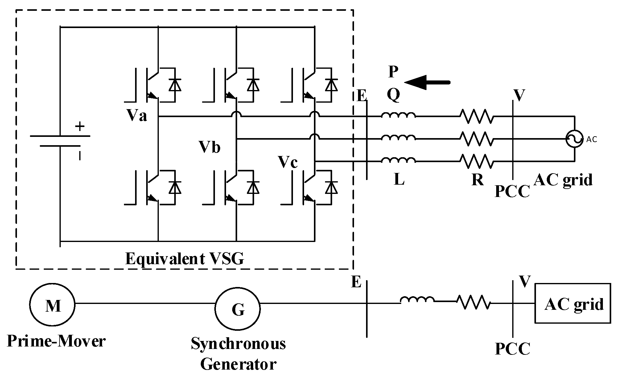
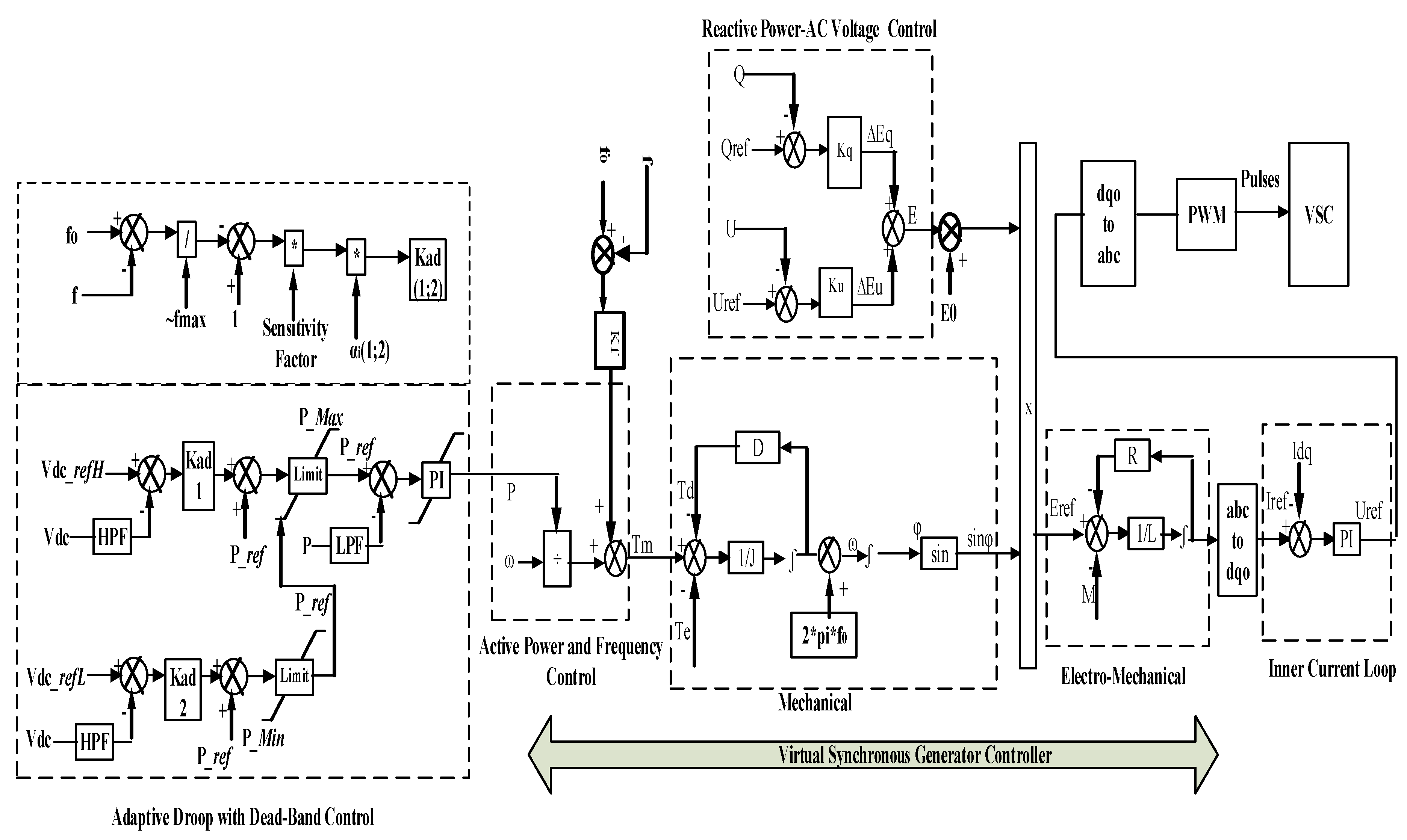
3. Adaptive Droop with a Dead-band and VSG

In an adaptive droop controller, a better system balance can be realized when a proportion of unbalanced power sharing by the AC networks with small frequency margin is decreased and vice versa. The unbalanced active power sharing is largely dependent on the active power (P) and DC voltage (V) droop coefficients [20]. The frequency margin (Mf) [0 1] and the adaptive droop coefficients (Kad) are given as:
M f = [ 1 | Δ f | Δ f max ] K a d = β · M f · α i
where ∆f, ∆fmax, β, αi and Kad are respectively the actual frequency and maximum frequency deviations, sensitivity factor, ordinary and adaptive droop gains. Since the frequency margin is typically less than unity, the P–V droop coefficient was significantly low. Thus, a sensitivity factor was included to guarantee a reasonable pace for unbalanced power sharing. A large sensitivity coefficient implies faster active power injection hence instability of the AC grids whereas a small sensitivity factor indicates slow unbalanced power sharing by the AC networks leading to rapid DC voltage changes. The sensitivity coefficients range recommended for research is given as [2 6] [20] but a factor of 4 was chosen as a better compromise for this paper.
Since a VSC having a droop with a dead-band control scheme can integrate power oscillation damping function for improved system’s stability and damping as suggested in [19], this study incorporated the VSG concept in the VSC. A second-order VSG controller model for this study is derived from the VSG-based system in Figure 2. The VSG concept is such that the DC network is equivalent to the prime-mover and the VSC station corresponding to the synchronous generator.
The power converter interface with VSG characteristics should have the same output as the synchronous generator swing equation in (11); where Sn is the rated capacity of the synchronous generator, H is the inertia time constant, J is the moment of inertia of the generator, ω is the mechanical angular velocity, Tm is the mechanical torque of the synchronous generator, Te is the synchronous generator electromagnetic torque, Td is the damping torque of the synchronous generator, D is the damping coefficient of synchronous generator and ω0 is the synchronous angular velocity of the grid. Equation (11) is the mechanical equation of the VSG.
J d ω d t = T m T e T d J d ω d t = T m T e D ( ω ω 0 )   where   J = H S n ω 0 2
The active power control is indirectly controlled by the mechanical torque. The mechanical torque consists of the torque command (T0) and the active frequency adjustment deviation (∆T) in (12), where Pref is the active power set-point, kf is the frequency droop gain while fo and f are the reference and measured frequencies respectively.
T m = T 0 + Δ T T m = P r e f ω + k f ( f 0 f )
The reactive power control uses the reactive-AC voltage drooping in (13), where E0 is the reference electromotive force, kq is the reactive power-AC voltage droop coefficient, Qref is the reactive power reference, Q is the measured reactive power, ku is the AC voltage regulation factor, Eref is the AC voltage reference and E is the measured AC voltage.
E = E 0 + Δ E Q + Δ E U E = E 0 + k q ( Q r e f Q ) + k u ( U r e f U )
The active power, reactive power-AC voltage and mechanical output loops provide the output voltage reference Eref, of the VSG in (14). Being a voltage source controlled VSG, the electromagnetic equation can be derived using the Kirchhoff’s voltage law at the output voltage set-point as shown in (15); where R and L are the resistance and inductance of the reactor, I is the line current, U is the input AC voltage and Eref is the output voltage set value.
E r e f = [ e a e b e c ] = [ E sin ( φ ) E sin ( φ 2 π / 3 ) E sin ( φ + 2 π / 3 ) ]
L d I d t = E r e f U R I
The electromagnetic loop gives the reference to the inner current loop in which the PI controller is integrated for excellent operation. The output of the inner current loop undergoes park transformation to generate the modulation signal to the PWM for giving gate signals to the VSC. Figure 3 shows the adaptive droop with dead-band integrated with the VSG controller.
In the VSG controller, there are two key parameters; the virtual inertia, J and the damping coefficient, D. When a network encounters a disturbance, J allows the VSC-based system to quickly change its output power and regulate the rate of change of frequency. On the other hand, D decreases any frequency fluctuations and provides a primary frequency regulation. It can be observed that a grid with low inertia experiences oscillations even after a small disturbance whereas one with large inertia has lowered stability due to a decreased phase margin. Hence in the VSG controller, a suitable virtual inertia value should accurately take into consideration the phase margin to realize how rapid the converter active power output attains a steady-state after disturbance. On the other hand, higher damping coefficient unlike larger inertia, lowers the oscillations in the system due to improved dynamic response to attain steady-state faster with lower overshoots. Usually, the VSG damping coefficient can be optimized unlike in the conventional synchronous generator whose damping power is fixed by the physical damper windings [20,21,22,23,24,25,26,27].

4. Hierarchical Control System

The hierarchical control structure of the multiterminal MVDC network includes the secondary control layer at the global level and the primary control system at the local converter level in MATLAB-PSCAD/EMTDC co-simulation platform. At the secondary level in MATLAB, the DC OPF algorithm receives the grid parameters, active power injections and load demand for determining the optimal droop settings for the VSCs during each time step. In the primary control system, the adaptive droop based system (including VSG) ensures the needed power balance and DC voltage control with improved adaptability and transient stability. The time constant for the secondary and primary control systems is in the scale of seconds and milliseconds respectively. Figure 4 shows the hierarchical control framework for the MVDC distribution network. It should be noted that the reference voltage to VSC 1 and VSC 2 was fed as Vdc_refH whereas Vdc_refL was obtained 0.4 units lower.

5. Simulation Test System, Results and Discussion
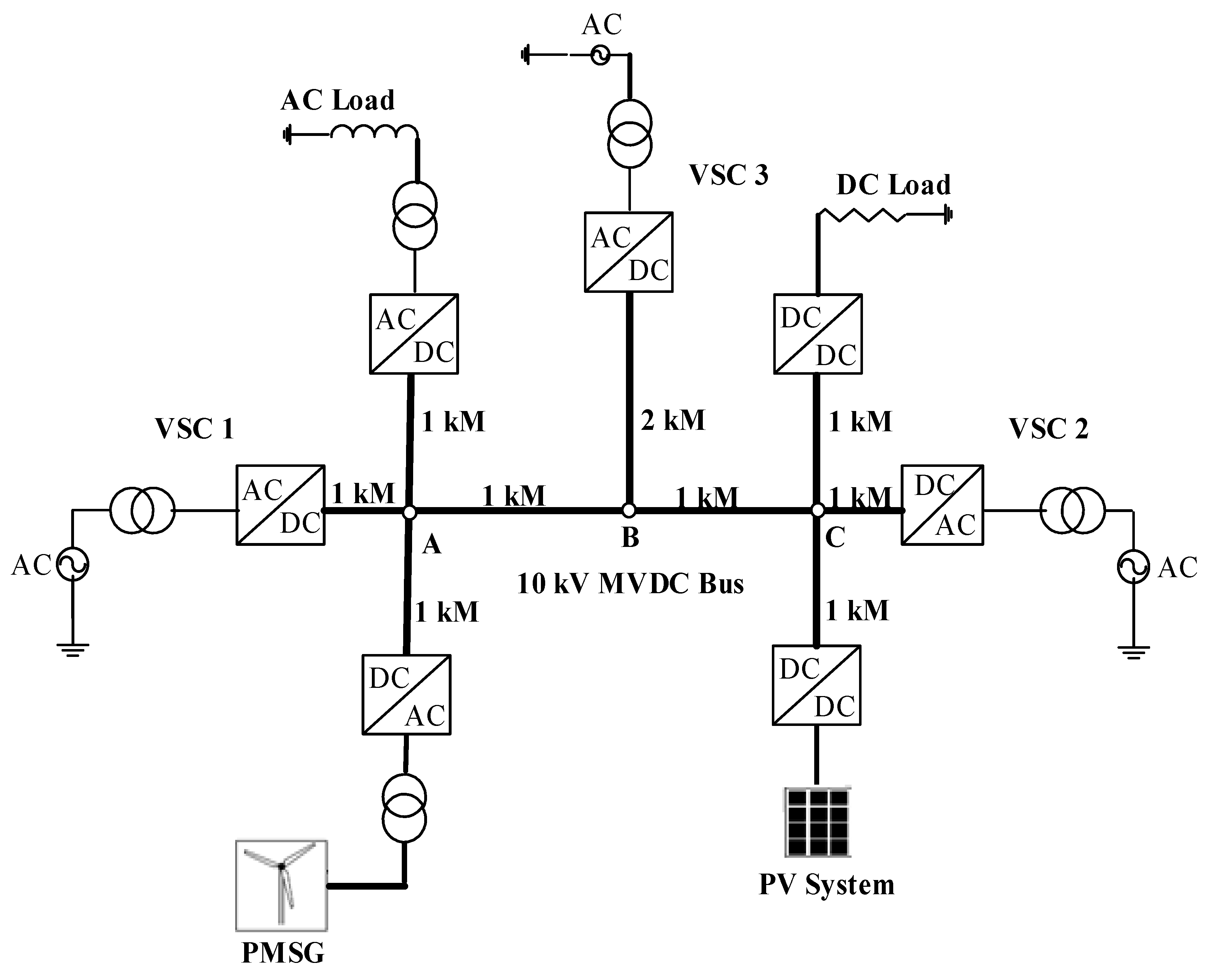
5.1. Test System

The MATLAB-PSCAD/EMTDC co-simulation was used to evaluate the proposed hierarchical scheme for the multiterminal MVDC distribution network in Figure 5. The MVDC network had three nodes 1, 6 and 10 such that their primary controllers were the adaptive droop with a dead-band, the adaptive droop control and the adaptive droop with a dead-band and VSG respectively. A weak AC system was connected to the converter at node 10. The MVDC network operated within a DC voltage range of 0.98–1.02 pu. A detailed model of the converters was used in the MVDC main circuit in PSCAD with a 250 µs simulation plot step and a time step of 10 µs. A smaller time step than the default value of 50 µs was preferable for more accurate simulation. In MATLAB, the DC OPF based secondary controller carried out the optimization within 4 s regularly updating PSCAD through the MATLAB/PSCAD interface. The PV system was regulated on incremental conductance MPPT algorithm, the PMSG controlled using P-Q control whereas the AC and DC loads operated on constant voltage control. Table 1, Table 2 and Table 3 display the key parameters of the MVDC distribution network.
The simulation of the DC OPF based secondary controller was carried out in a 32-bit MATLAB 2015a using fmincon nonlinear optimization. The MATLAB-PSCAD interface program was designed in 32-bit PSCAD 4.5 that had the primary circuit. In the final simulation, the IEEE–39 Bus System was incorporated in the primary circuit.

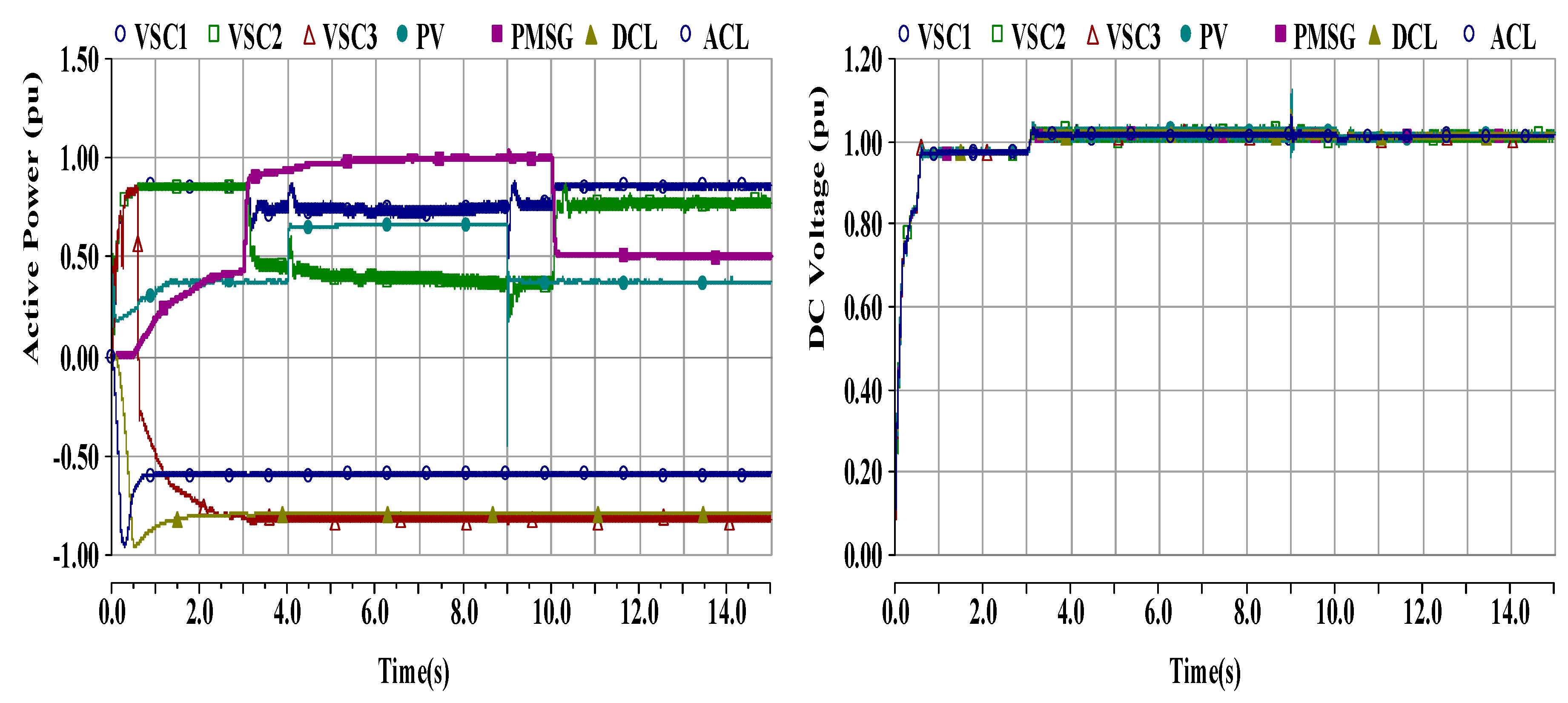
5.2. Simulation Results and Discussion

5.2.1. Case 1: Primary Control

In this simulation, the MVDC distribution network was investigated at the primary control level considering the droop with a dead-band versus the adaptive droop with a dead-band and VSG. The steady-state operation of the MVDC network was investigated for t = 6 s, then an additional load applied and withdrawn after t = 3 s. Figure 6 shows the active power and DC voltage profiles of the primary controllers.
It can be observed that in the system having a droop with dead-band control, VSC 2 (0.86 pu) supplied more active power than VSC 1 (0.71 pu) with fixed supply from wind and solar PV at rated loads from t = 2.8–6 s. This was unlike the adaptive droop with dead-band and VSG where the converters supplied almost the same amount i.e., VSC 1 (0.80 pu) and VSC 2 (0.77 pu). In each case, VSC 3 drew a fixed amount of active power almost the same as the rated DC load. During this time, the DC voltage was higher in the droop with dead-band (1.04 pu) than in the adaptive droop with dead-band and VSG (1.01 pu). When an additional load was applied at t = 6 s for t = 3 s, the DC voltage fell to 0.94 pu (a fall by 0.1 pu) in the droop with dead-band control compared to 0.98 pu (a drop by 0.03 pu) in the adaptive droop with a dead-band and VSG. Taking into consideration the set DC voltage range limits of 0.98–1.02 pu, the adaptive droop with dead-band and VSG control was more favorable for grid operation in regulating the DC voltage. The droop with a dead-band controller experiences characteristic steady-state error in active power flow in [18,19], which is further enriched when enhanced and included alongside VSG. The integration of VSG enhances effective power sharing and DC voltage control due to improved dynamic response of the droop-based scheme [20,21]. In this way, the proposed hierarchical control is based on the adaptive droop with a dead-band and VSG primary controller.

5.2.2. Case 2: Primary and Secondary Control

Scenarios with Non-Optimal and Optimal Secondary Control

The proposed hierarchical control scheme based on the adaptive droop with a dead-band and VSG primary controller was investigated with a non-optimal and DC OPF secondary controller. The MVDC distribution network was studied under steady-state operation with fixed supply from wind and solar PV as well as rated loads as illustrated in Figure 7. The DC OPF results are tabulated in Table 4. The MVDC network under non-optimal secondary controller had VSC 1 and VSC 2 equally supplied the active power at about 0.80 pu each. In the DC OPF secondary controller, the VSC 1 and VSC 2 supplied about 0.85 pu and 0.80 pu respectively. In each case, VSC 3 drew a fixed amount of active power almost the same as the rated DC load. In each case, the DC voltage was about 1.01–1.03 pu and 0.98–1.02 pu respectively, which showed the superiority of the DC OPF secondary controller when integrated in the system. The other difference between the two control schemes lay in the total grid losses in which the non-optimal scenario recorded 0.0238 pu (2.38 MW) while the optimized secondary controller effectively minimized the losses to 0.009 pu (0.9 MW). In this way, integrating the optimized secondary controller in the MVDC network significantly lowered the overall grid losses as well as guaranteed the DC voltage within the set limits similar to studies in [13,14,30].

Scenario with Optimal Secondary Control

The proposed hierarchical control consisting of the adaptive droop with dead-band and VSG primary control and the DC OPF secondary control for the MVDC distribution network was evaluated under variations in RE with rated loads. Figure 8 shows the MVDC distribution network under the proposed hierarchical control scheme during variations of REs. When wind and solar PV power was stepped up to 1.0 pu and 0.65 pu at t = 3 s and t = 4 s respectively, VSC 1 and VSC 2 reduced their initial supply to increase the RE share into the MVDC network. VSC 2 integrated more RE than VSC 1 whereas VSC 3 maintained a constant active power intake same as the DC load hence the DC voltage was regulated to about 0.98–1.01 pu. When the REs were curtailed to 0.5 pu and 0.38 pu at t = 10 s and t = 9 s respectively, VSC 1 and VSC 2 quickly increased their supply to maintain the DC voltage to about 1.0 pu. It can be observed that throughout the operation of the MVDC network, the DC voltage was maintained within the set margins. Although REs integrated in PCBS results in low equivalent inertia and damping posing a challenge in control and stability of power system as outlined in [22,31], the characteristics can be largely improved by integrating VSG at the primary control. Besides, incorporating adaptive droop control scheme increases higher accuracy in active power flow and DC voltage regulation [21,27] as demonstrated in the MVDC distribution network. At the secondary level, the DC OPF based controller optimizes the network performance as well as ensures accurate network DC voltage [14,30].
The proposed hierarchical control with DC OPF secondary controller was also tested in the IEEE-39 bus system in PSCAD/EMTDC such that the VSC 1, VSC 2 and VSC 3 terminals were connected to buses 8, 21 and 28 respectively as shown in Figure 9. The simulation involved fixed AC and DC loads while the REs were assumed to encounter severe faults at certain instances thus tripped/isolated then reinstated afterwards. Figure 10 shows the active power and DC voltage of the MVDC network when the REs were tripped and restored. When wind power trips at t = 4–7 s and t = 14–17 s, VSC 3 hugely reduced its intakes active power to 0.48 pu and 0.32 pu respectively. This enabled supplies to come from solar PV, VSC 1 and VSC 2 to manage the active power shortfall as well as maintain the network DC voltage. Consequently, this kept the DC voltage to 0.99 pu, which was within the lower bound of the set DC voltage range limit. Similarly, when solar PV was tripped at t = 9–12 s and t = 14–16 s, the swift sharing of the active power shortfall amongst wind generation as well as VSC 1 and VSC 2 enabled the DC voltage to attain 1.02 pu and 0.99 pu respectively, which were within the set voltage margins. It should be noted that the second tripping of PV was similar to the tripping of wind generation.

6. Conclusions

In this paper, a hierarchical control scheme consisting of the DC OPF secondary controller and the adaptive droop with dead-band and VSG primary controller was proposed for RE integration in the multiterminal MVDC distribution network. The simulation of the MVDC network under the proposed hierarchical control scheme was investigated considering variations in wind and solar PV power. The network was also connected to the standard IEEE-39 bus system and the hierarchical scheme tested by assessing the effect of tripping as well as restoration of REs. The results show that when the network experienced random variations in active power such as increasing generation, sudden reduction or tripping of REs, the adaptive droop based VSG primary control quickly maintained accurate active power sharing amongst the VSCs and regulated the deviations in DC voltage within the set voltage limits of 0.98–1.02 pu with enhanced inertia and a dynamic response. The DC OPF secondary control optimized the system’s losses by about 38% giving the optimal droop settings to the primary controller regularly to ensure suitable active power balance and DC voltage stability. In this way, the MVDC distribution network was stable and secure from any adverse impacts of possible power fluctuations typical of REs like wind and solar PV. The simulation results of the proposed control strategy are important in understanding the multiterminal MVDC distribution network as an effective and controllable platform for RE integration. Future studies can adapt the hierarchical control scheme in the energy management system of a similar or extended multiterminal MVDC distribution network and its performance validated on a hardware-in-the-loop experimental platform considering a wide range of scenarios to provide more practical insights for future commercial MVDC distribution network projects.

Author Contributions

Conceptualization, P.S. and A.X.; Methodology, P.S.; Software, P.S. and K.W.; Validation, P.S., K.W., G.A. and S.S.; Formal Analysis, P.S.; Investigation, P.S.; Resources, A.X.; Data Curation, P.S. and K.W.; Writing—Original Draft Preparation, P.S.; Writing—Review and Editing, G.A. and S.S.; Visualization, P.S. and A.X.; Supervision, A.X.; Project Administration, A.X.; Funding Acquisition, A.X. All authors have read and agreed to the published version of the manuscript.

Funding

This research was funded by the National Key Research and Development Program of China (Grant No. 2017YFB0903300) and National Science Foundation (Grant No. 51777065).

Conflicts of Interest

The authors declare no conflict of interest.

References

  1. Reed, G.F.; Grainger, B.M.; Sparacino, A.R.; Mao, Z. Ship to Grid: Medium-Voltage DC Concepts in Theory and Practice. IEEE Power Energy Mag. 2012, 10, 70–79. [Google Scholar] [CrossRef]
  2. Giannakis, A.; Peftitsis, D. MVDC Distribution Grids and Potential Applications: Future Trends and Protection Challenges. In Proceedings of the 2018 20th European Conference on Power Electronics and Applications (EPE’18 ECCE Europe), Riga, Latvia, 17–21 September 2018. [Google Scholar]
  3. Stieneker, M.; Doncker, R.W.D. Medium-voltage DC distribution grids in urban areas. In Proceedings of the 2016 IEEE 7th International Symposium on Power Electronics for Distributed Generation Systems (PEDG), Vancouver, BC, Canada, 27–30 June 2016. [Google Scholar]
  4. Gómez-Expósito, A.; Mauricio, J.M.; Maza-Ortega, J.M. VSC-Based MVDC Railway Electrification System. IEEE Trans. Power Deliv. 2014, 29, 422–431. [Google Scholar] [CrossRef]
  5. Reed, G.F.; Grainger, B.M.; Korytowski, M.J.; Taylor, E.J. Modeling, analysis, and validation of a preliminary design for a 20 kV medium voltage DC substation. In Proceedings of the IEEE 2011 EnergyTech, Cleveland, OH, USA, 25–26 May 2011. [Google Scholar]
  6. Kusic, G.L.; Reed, G.F.; Svensson, J.; Wang, Z. A case for medium voltage DC for distribution circuit applications. In Proceedings of the 2011 IEEE/PES Power Systems Conference and Exposition, Phoenix, AZ, USA, 20–23 March 2011. [Google Scholar]
  7. Mura, F.; Doncker, R.W.D. Design aspects of a medium-voltage direct current (MVDC) grid for a university campus. In Proceedings of the 8th International Conference on Power Electronics—ECCE Asia, Jeju, South Korea, 30 May–3 June 2011. [Google Scholar]
  8. Korompili, A.; Sadu, A.; Ponci, F.; Monti, A. Flexible Electric Networks of the Future: Project on Control and Automation in MVDC grids. In Proceedings of the International ETG Congress 2015; Die Energiewende - Blueprints for the new energy age, Bonn, Germany, 17–18 November 2015. [Google Scholar]
  9. Huang, Z.; Ma, J.; Zeng, J.; Gao, Y.; Yuan, Z.; Hu, Z.; Zhao, Y.; Liu, G. Research status and prospect of control and protection technology for DC distribution network. In Proceedings of the 2014 China International Conference on Electricity Distribution (CICED), Shenzhen, China, 23–26 September 2014. [Google Scholar]
  10. Yang, M.; Xie, D.; Zhu, H.; Lou, Y. Architectures and Control for Multi-terminal DC (MTDC) Distribution Network-A Review. In Proceedings of the 11th IET International Conference on AC and DC Power Transmission, Birmingham, UK, 10–12 February 2015. [Google Scholar]
  11. Aragüés-Peñalba, M.; Egea-Àlvarez, A.; Gomis-Bellmunt, O.; Sumper, A. Optimum voltage control for loss minimization in HVDC multi-terminal transmission systems for large offshore wind farms. Electr. Power Syst. Res. 2012, 89, 54–63. [Google Scholar] [CrossRef]
  12. Vrana, T.K.; Beerten, J.; Belmans, R.; Fosso, O.B. A classification of DC node voltage control methods for HVDC grids. Electr. Power Syst. Res. 2013, 103, 137–144. [Google Scholar] [CrossRef] [Green Version]
  13. Pinto, R.T.; Bauer, P.; Rodrigues, S.F.; Wiggelinkhuizen, E.J.; Pierik, J.; Ferreira, B. A Novel Distributed Direct-Voltage Control Strategy for Grid Integration of Offshore Wind Energy Systems Through MTDC Network. IEEE Trans. Ind. Electron. 2013, 60, 2429–2441. [Google Scholar] [CrossRef]
  14. Gavriluta, C.; Candela, I.; Luna, A.; Gomez-Exposito, A.; Rodriguez, P. Hierarchical Control of HV-MTDC Systems With Droop-Based Primary and OPF-Based Secondary. IEEE Trans. Smart Grid 2015, 6, 1502–1510. [Google Scholar] [CrossRef]
  15. Meng, K.; Zhang, W.; Li, Y.; Dong, Z.Y.; Xu, Z.; Wong, K.P.; Zheng, Y. Hierarchical SCOPF Considering Wind Energy Integration Through Multiterminal VSC-HVDC Grids. IEEE Trans. Power Syst. 2017, 32, 4211–4221. [Google Scholar] [CrossRef]
  16. Ji, Y.; Yuan, Z.; Zhao, J.; Lu, C.; Wang, Y.; Zhao, Y.; Li, Y.; Han, Y. Hierarchical control strategy for MVDC distribution network under large disturbance. IET Gener. Transm. Distrib. 2018, 12, 2557–2565. [Google Scholar] [CrossRef]
  17. Ji, Y.; Yuan, Z.; Zhao, J.; Zhao, Y.; Li, G.; Li, Y. Control scheme for multi-terminal VSC-based medium-voltage DC distribution networks. J. Eng. 2019, 2019, 2935–2940. [Google Scholar] [CrossRef]
  18. Yousefpoor, N.; Bhattacharya, S. Control and dynamic performance evaluation of Multi-Terminal DC grid. In Proceedings of the 2015 IEEE Power & Energy Society General Meeting, Denver, CO, USA, 26–30 July 2015. [Google Scholar]
  19. Simiyu, P.; Xin, A.; Bitew, G.T.; Shahzad, M.; Kunyu, W.; Tuan, L.K. Review of the DC voltage coordinated control strategies for multi-terminal VSC-MVDC distribution network. J. Eng. 2019, 2019, 1462–1468. [Google Scholar] [CrossRef]
  20. Wang, R.; Chen, L.; Zheng, T.; Mei, S. VSG-based adaptive droop control for frequency and active power regulation in the MTDC system. CSEE J. Power Energy Syst. 2017, 3, 260–268. [Google Scholar] [CrossRef]
  21. Kuang, Y.; Li, Y.; Wang, W.; Cao, Y. An adaptive virtual synchronous generator control strategy for VSC-MTDC systems and sensitivity analysis of the parameters. In Proceedings of the 2018 13th IEEE Conference on Industrial Electronics and Applications (ICIEA), Wuhan, China, 31 May–2 June 2018. [Google Scholar]
  22. Tamrakar, U.; Shrestha, D.; Maharjan, M.; Bhattarai, P.B.; Hansen, M.T.; Tonkoski, R. Virtual Inertia: Current Trends and Future Directions. Appl. Sci. 2017, 7, 654. [Google Scholar] [CrossRef]
  23. Zhong, Q. Virtual Synchronous Machines: A unified interface for grid integration. IEEE Power Electron. Mag. 2016, 3, 18–27. [Google Scholar] [CrossRef]
  24. Meng, X.; Liu, J.; Liu, Z. A Generalized Droop Control for Grid-Supporting Inverter Based on Comparison Between Traditional Droop Control and Virtual Synchronous Generator Control. IEEE Trans. Power Electron. 2019, 34, 5416–5438. [Google Scholar] [CrossRef]
  25. Cao, Y.; Wang, W.; Li, Y.; Tan, Y.; Chen, C.; He, L.; Häger, U.; Rehtanz, C. A Virtual Synchronous Generator Control Strategy for VSC-MTDC Systems. IEEE Trans. Energy Convers. 2018, 33, 750–761. [Google Scholar] [CrossRef]
  26. Liu, J.; Miura, Y.; Ise, T. Comparison of Dynamic Characteristics between Virtual Synchronous Generator and Droop Control in Inverter-Based Distributed Generators. IEEE Trans. Power Electron. 2016, 31, 3600–3611. [Google Scholar] [CrossRef]
  27. Li, C.; Li, Y.; Cao, Y.; Zhu, H.; Rehtanz, C.; Häger, U. Virtual Synchronous Generator Control for Damping DC-Side Resonance of VSC-MTDC System. IEEE J. Emerg. Sel. Top. Power Electron. 2018, 6, 1054–1064. [Google Scholar] [CrossRef]
  28. Bathurst, G.; Hwang, G.; Tejwani, L. MVDC—The New Technology for Distribution Networks. In Proceedings of the 11th IET International Conference on AC and DC Power Transmission, Birmingham, UK, 10–12 February 2015. [Google Scholar]
  29. Hunter, L.; Booth, C.; Finney, S.; Ferré, A.J. MVDC Network Balancing for Increased Penetration of Low Carbon Technologies. In Proceedings of the 2018 IEEE PES Innovative Smart Grid Technologies Conference Europe (ISGT-Europe), Sarajevo, Bosnia-Herzegovina, 21–25 October 2018. [Google Scholar]
  30. Bibaya, L.; Liu, C.; Li, G. Optimal Hierarchical Voltage Control for VSC-MTDC Distribution Network. In Proceedings of the 2019 IEEE Innovative Smart Grid Technologies—Asia (ISGT Asia), Chengdu, China, 21–24 May 2019. [Google Scholar]
  31. Liu, Y.; Hao, M.; He, Y.; Zang, C.; Zeng, P. Review and Applications of Virtual Synchronous Machines Technologies. In Proceedings of the 2019 IEEE Innovative Smart Grid Technologies—Asia (ISGT Asia), Chengdu, China, 21–24 May 2019. [Google Scholar]
  32. Rouzbehi, K.; Miranian, A.; Luna, A.; Rodriguez, P. DC Voltage Control and Power Sharing in Multiterminal DC Grids Based on Optimal DC Power Flow and Voltage-Droop Strategy. IEEE J. Emerg. Sel. Top. Power Electron. 2014, 2, 1171–1180. [Google Scholar] [CrossRef]
  33. Beerten, J.; Cole, S.; Belmans, R. Generalized Steady-State VSC MTDC Model for Sequential AC/DC Power Flow Algorithms. IEEE Trans. Power Syst. 2012, 27, 821–829. [Google Scholar] [CrossRef] [Green Version]
  34. Khazaei, J.; Miao, Z.; Piyasinghe, L.; Fan, L. Minimizing DC system loss in multi-terminal HVDC systems through adaptive droop control. Electr. Power Syst. Res. 2015, 126, 78–86. [Google Scholar] [CrossRef]
  35. Hu, B.; Xie, K.; Yang, H.; Jiang, Z. Evaluation model and algorithm for wind farm capacity credit considering effect of storage systems using the bisection method. In Proceedings of the 2014 IEEE PES General Meeting | Conference & Exposition, National Harbor, MD, USA, 27–31 July 2014. [Google Scholar]
Figure 1. DC optimal power flow (OPF) algorithm in the secondary controller.
Electronics 09 00506 g001
Figure 2. Virtual synchronous generation (VSG)-based system.
Electronics 09 00506 g002
Figure 3. Adaptive droop with a dead-band and VSG.
Electronics 09 00506 g003
Figure 4. Hierarchical control system framework.
Electronics 09 00506 g004
Figure 5. A 10-node radial multiterminal VSC-medium voltage DC (MVDC) distribution network test system.
Electronics 09 00506 g005
Figure 6. Active power and DC voltage of the primary controller; (a) droop with a dead-band and (b) adaptive droop with a dead-band and VSG.
Electronics 09 00506 g006
Figure 7. Active power and DC voltage of the adaptive droop with a dead-band and VSG primary controller with (a) non-optimal and (b) DC OPF secondary control.
Electronics 09 00506 g007
Figure 8. Active power and DC voltage under the proposed hierarchical control with DC OPF secondary control during variations of renewable energies (REs).
Electronics 09 00506 g008
Figure 9. Multiterminal MVDC distribution network connected to the IEEE–39 Bus System.
Electronics 09 00506 g009
Figure 10. Active power and DC voltage of the MVDC network connected to the IEEE-39 Bus System under the proposed hierarchical control scheme with DC OPF secondary during tripping of REs.
Electronics 09 00506 g010
Table 1. Key parameters of the MVDC network.
NoParametersNominal Value
1.Utility AC Voltage/Frequency10 kV/50 Hz
2.Reactor Resistance/Inductance 0.003 Ω/0.002 H
3.AC Transformer Ratings100 MVA;10/5 kV
4.VSC 1/2/3 Active Power Rating8.1/8.1/8.1 MW
5.MVDC Link Capacitance20000 μF
6.MVDC Grid Voltage10 kV
7.PMSG rated Voltage/Power0.69 kV/5 MVA
8.PMSG Side Transformer Rating0.69/5 kV
9.PV Array Power3.34 MW
10.PV Array Output Voltage/Vmpp5 kV
11.Boost Converter Inductance0.05 H
12.PV-side Capacitance1000 μF
13.Buck Converter Inductance 1 H
14.Buck-side Capacitance1000 μF
14.DC Load Voltage/Power 4 kV/8.0 MW
15.AC load Power2.0 kV/6.0 MW
16.π-DC Cable R/ L/C per kM139 mΩ/15.9 mH/23.1 μF
17.Virtual Inertia/Damping Factor81 kg.m2/8765 N.m.s/rad
Table 2. MVDC network line parameters.
FromToRline (Ω)
120.139
230.139
240.139
250.139
560.278
570.139
780.139
790.139
7100.139
Table 3. MVDC network converter parameters.
NodeTypePower Min (pu)Power Max (pu)Droop (p.u)
1AC-DC−1.01.00.30
2-0.00.00.00
3AC-DC−0.6−1.00.00
4AC-DC0.71.00.00
5-0.00.00.00
6AC-DC−1.01.00.15
7-0.00.00.00
8DC-DC−0.7−0.70.00
9DC-DC0.40.650.00
10AC-DC−1.01.00.20
Table 4. DC OPF results.
NodesVdc (pu)P (pu)
11.01110.8431
21.01030.0000
31.0005−0.5963
41.02000.5000
51.00970.0000
61.0112−0.8100
71.00840.0000
80.9984−0.8000
91.01420.3650
101.01140.7703

