A Low Cross-Polarization Configuration Method for Phased Array Radar Antenna


Abstract
1. Introduction
2. Formulation
2.1. Radiation Model with Elliptical Polarization
2.2. Radiation Model of Crossed Dipoles
2.3. PSM Using Elliptically Polarized Wave
3. Simulation Results and Analyses
3.1. Linear Polarization
3.2. Circular Polarization
3.3. Elliptical Polarization
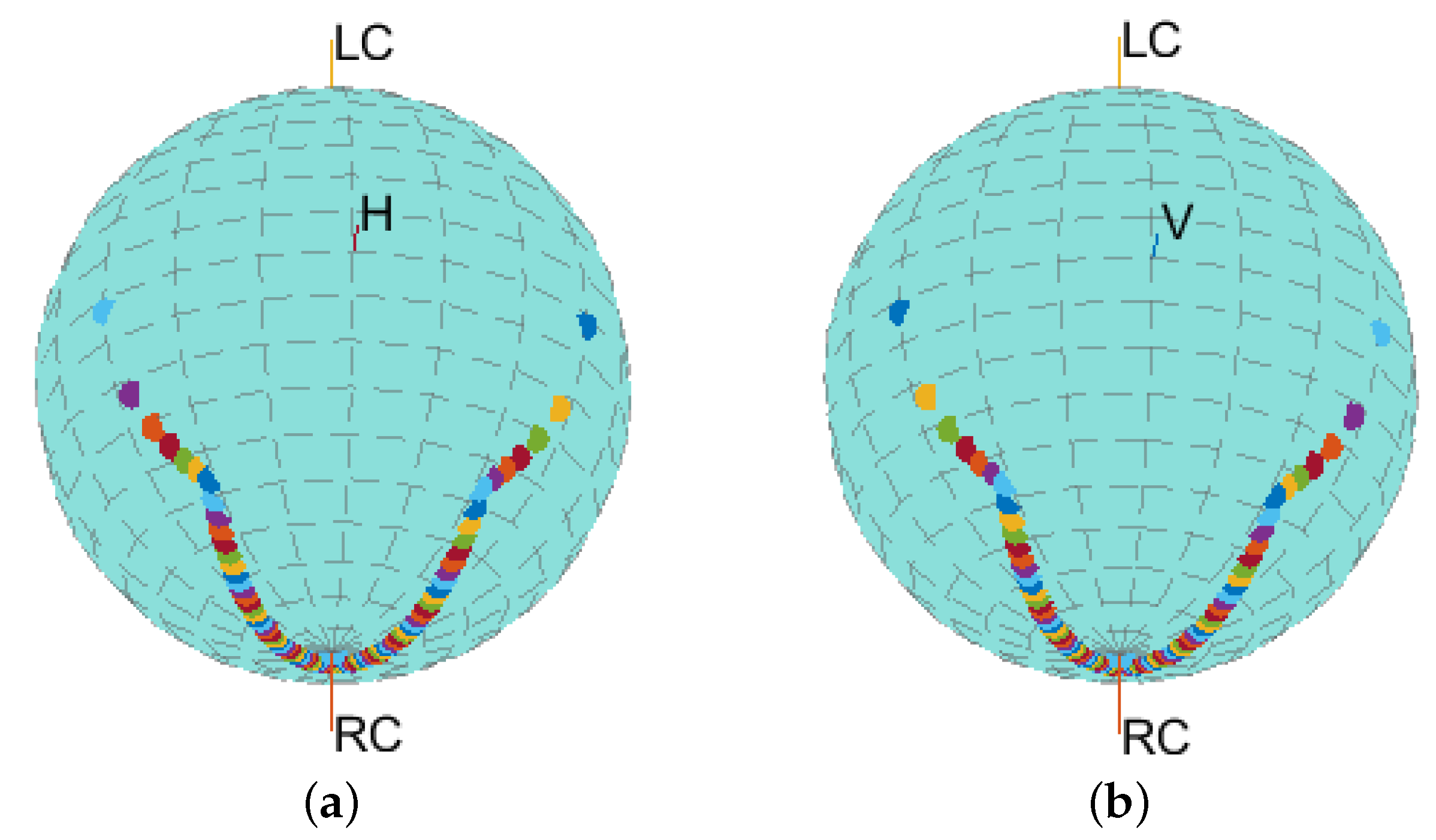
3.4. Polarization Measurement Using the Elliptically Polarized Wave
4. Conclusions
Author Contributions
Funding
Acknowledgments
Conflicts of Interest
References
- Zhang, G.; Doviak, R.J.; Zrnić, D.S.; Crain, J.; Staiman, D.; Al-Rashid, Y. Phased Array Radar Polarimetry for Weather Sensing: A Theoretical Formulation for Bias Corrections. IEEE Trans. Geosci. Remote Sens. 2009, 47, 3679–3689. [Google Scholar] [CrossRef]
- Stailey, J.E.; Hondl, K.D. Multifunction Phased Array Radar for Aircraft and Weather Surveillance. Proc. IEEE 2016, 104, 649–659. [Google Scholar] [CrossRef]
- Zhang, G.; Mahale, V.; Putnam, B.J.; Qi, Y.; Cao, Q.; Byrd, A.; Bukovcic, P.; Zrnić, D.S.; Gao, J.; Xue, M.; et al. Current Status and Future Challenges of Weather Radar Polarimetry: Bridging the Gap between Radar Meteorology/Hydrology/Engineering and Numerical Weather Prediction. Adv. Atmos. Sci. 2019, 36, 571–588. [Google Scholar] [CrossRef]
- Fulton, C.; Yeary, M.; Thompson, D.; Lake, J.; Mitchell, A. Digital Phased Arrays: Challenges and Opportunities. Proc. IEEE 2016, 104, 487–503. [Google Scholar] [CrossRef]
- Pang, C.; Hoogeboom, P.; Chevalier, F.L.; Russchenberg, H.W.J.; Dong, J.; Wang, T.; Wang, X. Polarimetric Bias Correction of Practical Planar Scanned Antennas for Meteorological Applications. IEEE Trans. Geosci. Remote Sens. 2016, 54, 1488–1504. [Google Scholar] [CrossRef]
- Fulton, C.; Chappell, W. Calibration of panelized polarimetric phased array radar antennas: A case study. In Proceedings of the 2010 IEEE International Symposium on Phased Array Systems and Technology, Waltham, MA, USA, 12–15 October 2010; pp. 860–867. [Google Scholar] [CrossRef]
- Lei, L.; Zhang, G.; Doviak, R.J. Bias Correction for Polarimetric Phased-Array Radar with Idealized Aperture and Patch Antenna Elements. IEEE Trans. Geosci. Remote Sens. 2013, 51, 473–486. [Google Scholar] [CrossRef]
- Pang, C.; Dong, J.; Wang, T.; Wang, X. A Polarimetric Calibration Error Model for Dual-Polarized Antenna Element Patterns. IEEE Antennas Wirel. Propag. Lett. 2016, 15, 782–785. [Google Scholar] [CrossRef]
- Fulton, C.; Herd, J.; Karimkashi, S.; Zhang, G.; Zrnić, D. Dual-polarization challenges in weather radar requirements for multifunction phased array radar. In Proceedings of the 2013 IEEE International Symposium on Phased Array Systems and Technology, Waltham, MA, USA, 15–18 October 2013; pp. 494–501. [Google Scholar] [CrossRef]
- Fulton, C.; Salazar, J.L.; Zhang, Y.; Zhang, G.; Kelly, R.; Meier, J.; McCord, M.; Schmidt, D.; Byrd, A.D.; Bhowmik, L.M.; et al. Cylindrical Polarimetric Phased Array Radar: Beamforming and Calibration for Weather Applications. IEEE Trans. Geosci. Remote Sens. 2017, 55, 2827–2841. [Google Scholar] [CrossRef]
- Wang, Z.; Pang, C.; Li, Y.; Wang, X. Bias Correction to Antenna Frequency Response for Wideband Polarimetric Phased Array Radar. Electronics 2019, 8, 1075. [Google Scholar] [CrossRef]
- Wang, Z.; Pang, C.; Li, Y.; Wang, X. Bias Correction for Polarization Measurement in Phased Array Antenna Via Pattern Reconstruction Method. IEEE Access 2019, 7, 150006–150012. [Google Scholar] [CrossRef]
- Yin, J.; Hoogeboom, P.; Unal, C.; Russchenberg, H.; van der Zwan, F.; Oudejans, E. UAV-Aided Weather Radar Calibration. IEEE Trans. Geosci. Remote Sens. 2019, 57, 10362–10375. [Google Scholar] [CrossRef]
- Milione, G.; Sztul, H.; Nolan, D.; Alfano, R. Higher-order Poincaré sphere, Stokes parameters, and the angular momentum of light. Phys. Rev. Lett. 2011, 107, 053601. [Google Scholar] [CrossRef] [PubMed]
- Yi, X.; Liu, Y.; Ling, X.; Zhou, X.; Ke, Y.; Luo, H.; Wen, S.; Fan, D. Hybrid-order Poincaré sphere. Phys. Rev. A 2015, 91, 023801. [Google Scholar] [CrossRef]
- Zrnić, D.; Doviak, R.; Zhang, G.; Ryzhkov, A. Bias in Differential Reflectivity due to Cross Coupling through the Radiation Patterns of Polarimetric Weather Radars. J. Atmos. Ocean. Technol. 2010, 27, 1624–1637. [Google Scholar] [CrossRef]
- Zrnić, D.S.; Zhang, G.; Doviak, R.J. Bias Correction and Doppler Measurement for Polarimetric Phased-Array Radar. IEEE Trans. Geosci. Remote Sens. 2011, 49, 843–853. [Google Scholar] [CrossRef]
- Bringi, V.; Chandrasekar, V. Polarimetric Doppler Weather Radar: Principles And Applications; Cambridge University Press: Cambridge, UK, 2001. [Google Scholar]
- Wang, Y.; Chandrasekar, V. Polarization isolation requirements for linear dual-polarization weather Radar in simultaneous transmission mode of operation. IEEE Trans. Geosci. Remote Sens. 2006, 44, 2019–2028. [Google Scholar] [CrossRef]


© 2020 by the authors. Licensee MDPI, Basel, Switzerland. This article is an open access article distributed under the terms and conditions of the Creative Commons Attribution (CC BY) license (http://creativecommons.org/licenses/by/4.0/).
Share and Cite
Li, Y.; Wang, Z.; Pang, C.; Wang, X. A Low Cross-Polarization Configuration Method for Phased Array Radar Antenna. Electronics 2020, 9, 396. https://doi.org/10.3390/electronics9030396
Li Y, Wang Z, Pang C, Wang X. A Low Cross-Polarization Configuration Method for Phased Array Radar Antenna. Electronics. 2020; 9(3):396. https://doi.org/10.3390/electronics9030396
Chicago/Turabian StyleLi, Yongzhen, Zhanling Wang, Chen Pang, and Xuesong Wang. 2020. "A Low Cross-Polarization Configuration Method for Phased Array Radar Antenna" Electronics 9, no. 3: 396. https://doi.org/10.3390/electronics9030396
APA StyleLi, Y., Wang, Z., Pang, C., & Wang, X. (2020). A Low Cross-Polarization Configuration Method for Phased Array Radar Antenna. Electronics, 9(3), 396. https://doi.org/10.3390/electronics9030396