A Review of PHIL Testing for Smart Grids—Selection Guide, Classification and Online Database Analysis

 , , and
Abstract
1. Introduction
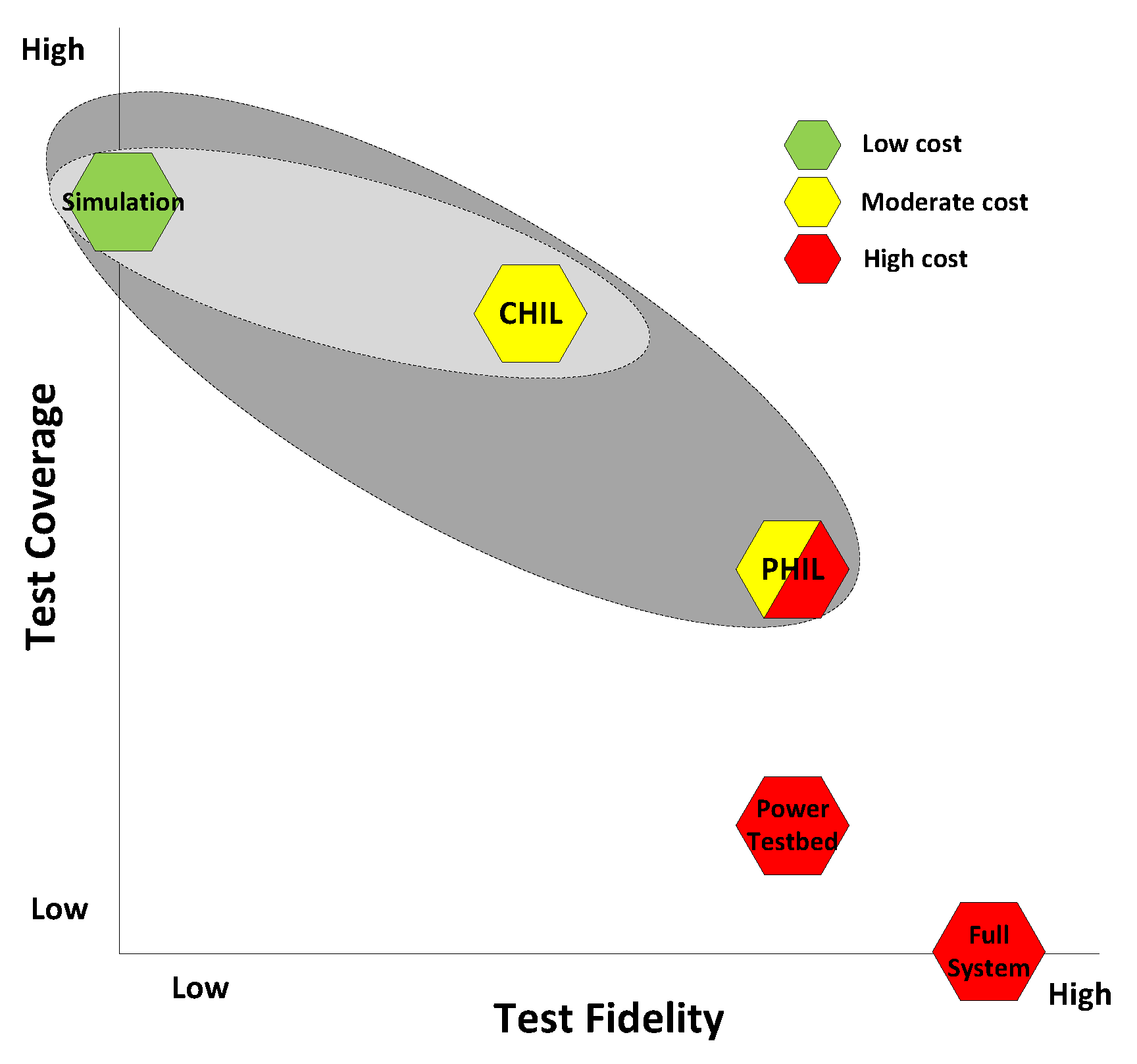
2. PHIL System Selection Guide
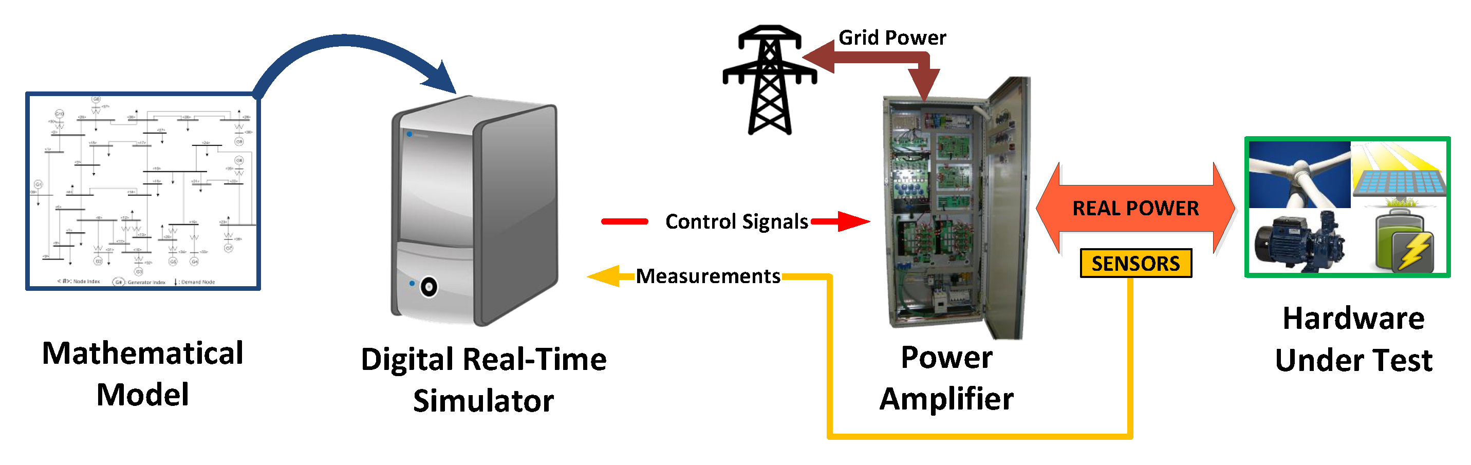
- The range of voltage, current and power that the PA has to deliver to test HUT at nominal behaviour.
- The operation quadrants, depending on the apparent HUT nominal power.
- The minimum bandwidth, e.g., Amitkumar et al. [17] suggested that the PA needs to have five times more bandwidth than the test inverter’s current loop for an accurate emulation.
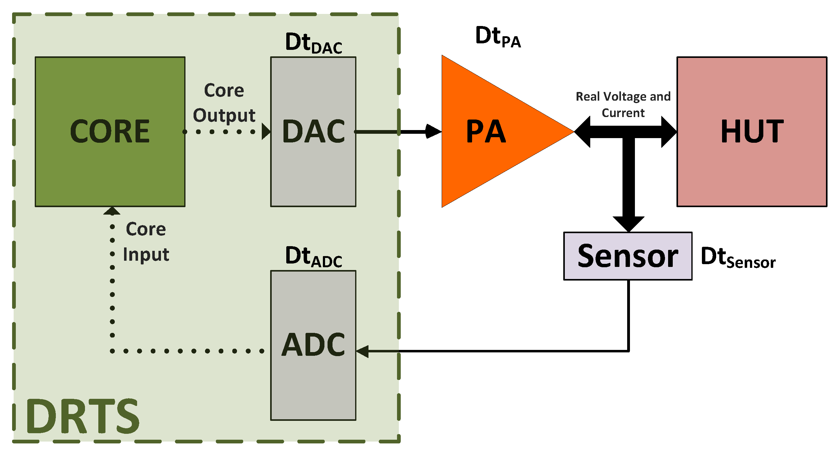
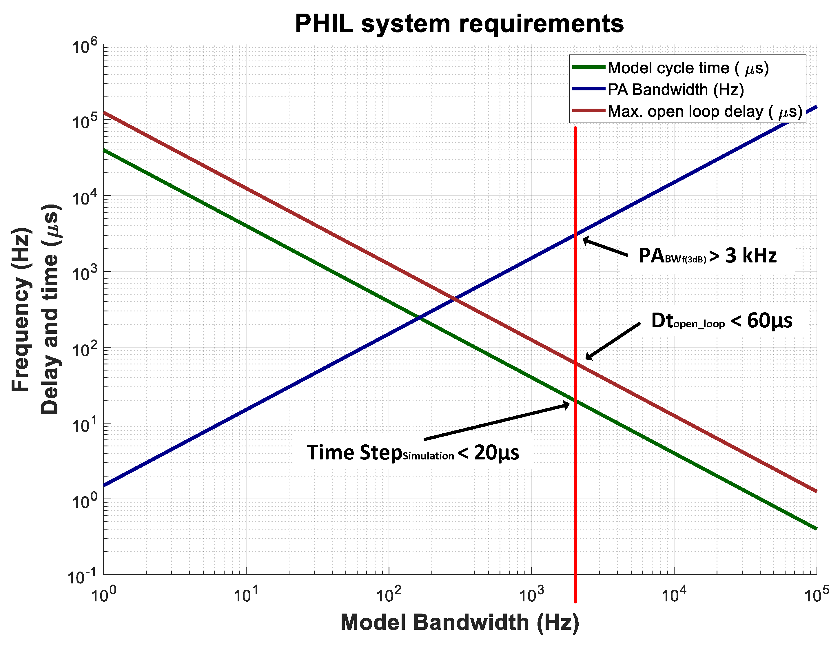
- Maximum open delay: Figure 4 shows a set-up where the set-point and measurements are sent with an analogue signal. The total open-loop delay between the DRTS output and input is the sum of each delay in the loop:The maximum delay between “Core Output” and “Core Input” to ensure an open-loop phase shift less than −45° has to be:
- Minimum PA bandwidth: The open-loop phase shift at the PA frequency bandwidth is −45°. To obtain, at the most, an open-loop phase shift of −30°, the minimum bandwidth of the PA has to be at least 1.5 times wider than the highest frequency of the model to be simulated:
- Model cycle time: The maximum time-step that the simulator has to achieve depends on the highest dynamic or frequency bandwidth of the simulated model. To generate this highest frequency, Lemaire et al. [16] determined that the minimum time step must be at least 25 times less than the inverse of the desired frequency:
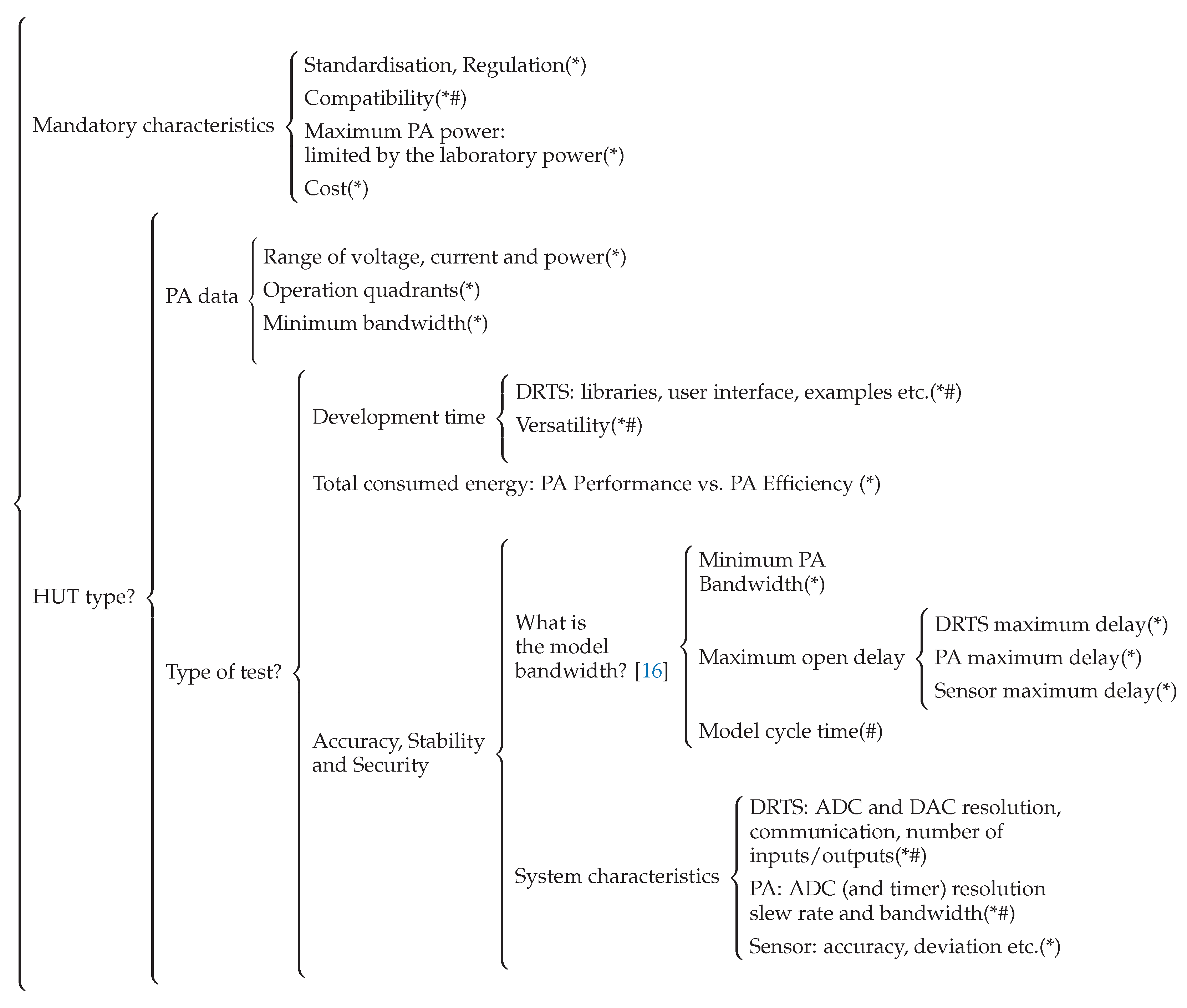
3. Information Classification for Reusability Purposes
- Real-Time Simulator
- –
- DRTS model and reference to the web page where the datasheet could be found.
- –
- If the DRTS it is not a commercial one:
- ∗
- Simulation environment: visual characteristics, examples, library models etc.
- ∗
- DAC and ADC resolution.
- ∗
- Hardware and software delays.
- ∗
- Different types of communication.
- ∗
- Solver types.
- Power Amplifier
- –
- PA model and a reference to the web page where the datasheet could be found.
- –
- Amplifier type: switched or linear.
- –
- If the power amplifier system is not a commercial one:
- ∗
- Working quadrants.
- ∗
- Maximum power.
- ∗
- Voltage and/or current bandwidth.
- ∗
- Voltage and/or current slew rate.
- ∗
- Efficiency.
- ∗
- Voltage and current THD.
- ∗
- Dimensions and weight.
- ∗
- Accuracy, ripple etc.
- Hardware Under Test
- –
- General description.
- –
- Model and reference to the web page where the datasheet could be found.
- Simulated model
- –
- Time step.
- –
- Model and a reference to the web page where the datasheet could be found.
- –
- Interface Algorithm (IA) used and why.
- –
- Power range and bandwidth.
- –
- Libraries and/or standard models used.
- –
- A block diagram figure is advisable.
- Test Results
- –
- Graphs and oscilloscope captures to check:
- ∗
- Desired and obtained output.
- ∗
- Accuracy and stability.
- ∗
- Slew rate.
- ∗
- Ripple.
- –
- Problems encountered during the test and how they have been solved.
- DRTS and PA interconnection
- –
- Analogue communication:
- ∗
- ADC resolution in both systems.
- ∗
- Delays in acquisition voltage.
- ∗
- Sample frequency.
- ∗
- Voltage range.
- –
- Digital communication:
- ∗
- Standard used.
- ∗
- Baud rate.
- ∗
- Set-point and measurement resolution.
- –
- Sensor types used and their main characteristics.
- Overall PHIL test
- –
- A figure scheme with the PHIL test bench.
- –
- A photograph of the complete PHIL test bench during an experiment.
- PHIL test Motivation
- –
- Type of test and its purpose.
- –
- References of the different kind of test consulted.
- –
- Reference to another PHIL test done in the laboratory.
- Final Conclusion
- –
- Determine the PHIL set-up usefulness for test purposes.
- –
- Clarification of the test bed limits.
- –
- Possible improvements for future testing.
4. PHIL Tests Database Analysis
4.1. Digital Real Time Simulator
4.2. Hardware under Test (HUT)
4.3. Power Amplifier
- Linear Amplifier:
- Switched Amplifier:
4.4. Interface Algorithm
4.5. Communication
5. Smart Grid PHIL System Sizing
- HUT types: Grid side power electronics.
- Type of tests: Renewable energy and storage systems integration.
- Simulated System: Electric grid [117].
- Model bandwidth: 2 kHz (step time of 50 s).
- Laboratory maximum power: 100 kW.
- There are two main DRTS companies that the scientific community uses to simulate an electric grid with a high number of nodes in real-time. It seems that there are not so many options in the market to simulate this kind of complex electric grid in real-time.
- There are no tests in which a time step below 50 s to simulate an electric grid in real-time is used. Therefore, if the test bed target changes and the model bandwidth increases, undesirable problems could appear.
- The main interests of the laboratories are to know how the PV inverters and storage systems will behave in each electric grid. The test of another kind of grid side power electronics system will need a more detailed study. A less restrictive database filtering process, with the purpose of obtaining more results, could help to find more information.
- Both linear and switched amplifiers are used. Consequently, the used PA topology will depend on other factors such as price.
- More than half of the reports searched for were published during the last year. It shows that the state of the art is up-to-date and, therefore, the conclusions are more reliable.
6. Conclusions
Author Contributions
Funding
Conflicts of Interest
Abbreviations
| ADC | Analog-to-Digital Converter |
| CPU | Central Processing Unit |
| DAC | Digital-to-Analog Converter |
| DIM | Damping Impedance Method |
| DSP | Digital Signal Processor |
| EMC | Electromagnetic Compatibility |
| FPGA | Field-Programmable Gate Array |
| PV | Photovoltaic |
| THD | Total Harmonic Distortion |
References
- Siano, P. Demand response and smart grids—A survey. Renew. Sustain. Energy Rev. 2014, 30, 461–478. [Google Scholar] [CrossRef]
- European Technology Platform SmartGrids. SmartGrids SRA 2035 Strategic Research Agenda Update of the SmartGrids SRA 2007 for the Needs by the Year 2035. Smart Grids European Technology Platform. 2012. Available online: https://www.etip-snet.eu/wp-content/uploads/2017/04/sra2035.pdf (accessed on 14 January 2020).
- Monti, A.; Ponci, F. Power Grids of the Future: Why Smart Means Complex. In Proceedings of the Complexity in Engineering (COMPENG ’10), Rome, Italy, 22–24 February 2010; pp. 7–11. [Google Scholar] [CrossRef]
- Liserre, M.; Sauter, T.; Hung, J.Y. Future Energy Systems: Integrating Renewable Energy Sources into the Smart Power Grid Through Industrial Electronics. IEEE Ind. Electron. Mag. 2010, 4, 18–37. [Google Scholar] [CrossRef]
- Slootweg, H. Smart Grids—The future or fantasy? In Proceedings of the Smart Metering—Making It Happen, 2009 IET, London, UK, 19 February 2009; pp. 1–19. [Google Scholar] [CrossRef]
- Strasser, T.; Pröstl Andrén, F.; Lauss, G.; Bründlinger, R.; Brunner, H.; Moyo, C.; Seitl, C.; Rohjans, S.; Lehnhoff, S.; Palensky, P.; et al. Towards holistic power distribution system validation and testing—an overview and discussion of different possibilities. E & I Elektrotechnik Und Informationstechnik 2017, 134, 71–77. [Google Scholar] [CrossRef]
- Mylonas, E.; Tzanis, N.; Birbas, M.; Birbas, A. An Automatic Design Framework for Real-Time Power System Simulators Supporting Smart Grid Applications. Electronics 2020, 9, 299. [Google Scholar] [CrossRef]
- Tuballa, M.L.; Abundo, M.L. A review of the development of Smart Grid technologies. Renew. Sustain. Energy Rev. 2016, 59, 710–725. [Google Scholar] [CrossRef]
- Vijay, A.S.; Doolla, S.; Chandorkar, M.C. Real-Time Testing Approaches for Microgrids. IEEE J. Emerg. Sel. Top. Power Electron. 2017, 5, 1356–1376. [Google Scholar] [CrossRef]
- Mariachet, J.E.; Matas, J.; Martín, H.; Li, M.; Guan, Y.; Guerrero, J.M. A power calculation algorithm for single-phase droop-operated-inverters considering linear and nonlinear loads HIL-assessed. Electronics 2019, 8, 1366. [Google Scholar] [CrossRef]
- Huo, Y.; Gruosso, G. Ancillary service with grid connected PV: A real-time hardware-in-the-loop approach for evaluation of performances. Electronics 2019, 8, 809. [Google Scholar] [CrossRef]
- Salcedo, R.; Nowocin, J.K.; Smith, C.L.; Rekha, R.P.; Limpaecher, E.R.; La Penta, J. Development of a Real-Time Hardware- in-the-Loop Power Systems Simulation Platform to Evaluate Commercial Microgrid Controllers. Technical Report February, Lincoln Laboratory—Massachusetts Institute of Technology. Available online: http://www.dtic.mil/docs/citations/ADA635943 (accessed on 14 January 2020).
- Carne, G.D.; Langwasser, M.; Gao, X.; Buticchi, G.; Liserre, M. Power-Hardware-In-Loop Setup for Power Electronics Tests. In Proceedings of the PCIM Europe 2017; International Exhibition and Conference for Power Electronics, Intelligent Motion, Renewable Energy and Energy Management, Nuremberg, Germany, 16–18 May 2017; pp. 1–7. [Google Scholar]
- Kashani, M.G.; Pulakhandam, H.; Bhattacharya, S.; Katiraei, F.; Kaiser, D. Design considerations and test setup assessment for power hardware in the loop testing. In Proceedings of the 2017 IEEE Industry Applications Society Annual Meeting, Cincinnati, OH, USA, 1–5 October 2017; pp. 1–8. [Google Scholar] [CrossRef]
- Torres-Olguin, R.E.; Endegnanew, A.G.; D’Arco, S. Power-hardware-in-the-loop approach for emulating an offshore wind farm connected with a VSC-based HVDC. In Proceedings of the 2017 IEEE Conference on Energy Internet and Energy System Integration (EI2), Beijing, China, 26–28 November 2017; pp. 1–6. [Google Scholar] [CrossRef]
- Lemaire, M.; Pammer, G.; Black, B. Smarter drives need smarter development. In Proceedings of the 2016 IEEE Transportation Electrification Conference and Expo (ITEC), Dearborn, MI, USA, 27–29 June 2016; pp. 1–63. [Google Scholar] [CrossRef]
- Amitkumar, K.S.; Kaarthik, R.S.; Pillay, P. A versatile power-hardware-in-the-loop based emulator for rapid testing of electric drives. In Proceedings of the 2017 IEEE Energy Conversion Congress and Exposition (ECCE), Cincinnati, OH, USA, 1–5 October 2017; pp. 5468–5474. [Google Scholar] [CrossRef]
- Orr, M. Selecting a Linear or PWM Power Source. Technical Report. Available online: https://www.testworld.com/wp-content/uploads/Selecting-a-Linear-or-PWM-Power-Source.pdf (accessed on 14 January 2020).
- Lehfuss, F.; Lauss, G.; Kotsampopoulos, P.; Hatziargyriou, N.; Crolla, P.; Roscoe, A. Comparison of multiple power amplification types for power Hardware-in-the-Loop applications. In Proceedings of the 2012 Complexity in Engineering (COMPENG), Aachen, Germany, 11–13 June 2012; pp. 1–6. [Google Scholar] [CrossRef]
- Ren, W.; Steurer, M.; Baldwin, T.L. An effective method for evaluating the accuracy of Power Hardware-in-the-Loop simulations. In Proceedings of the Industrial and Commercial Power Systems Technical Conference (ICPS 2008. IEEE/IAS), Clearwater Beach, FL, USA, 4–8 May 2008; pp. 1–6. [Google Scholar] [CrossRef]
- Ebe, F.; Idlbi, B.; Stakic, D.E.; Chen, S.; Kondzialka, C.; Casel, M.; Heilscher, G.; Seitl, C.; Bründlinger, R.; Strasser, T.I. Comparison of power hardware-in-the-loop approaches for the testing of smart grid controls. Energies 2018, 11, 3381. [Google Scholar] [CrossRef]
- Bélanger, J.; Dufour, C.; Schoen, L. eMEGAsim: An Open High-Performance Architecture and Specification. In Proceedings of the International Conference on Power Systems (ICPS’07), Bangalore, India, 12–14 December 2007; pp. 1–6. [Google Scholar]
- Faruque, M.D.O.; Strasser, T.; Lauss, G.; Jalili-Marandi, V.; Forsyth, P.; Dufour, C.; Dinavahi, V.; Monti, A.; Kotsampopoulos, P.; Martinez, J.A.; et al. Real-Time Simulation Technologies for Power Systems Design, Testing, and Analysis. IEEE Power Energy Technol. Syst. J. 2015, 2, 63–73. [Google Scholar] [CrossRef]
- Westermann, D.; Kratz, M. A Real-Time Development Platform for the Next Generation of Power System Control Functions. IEEE Trans. Ind. Electron. 2010, 57, 1159–1166. [Google Scholar] [CrossRef]
- Ocnasu, D. Modélisation, Commande et Simulation Temps-Réel Hybride des Systèmes de Génération Non Conventionnels. Ph.D. Thesis, Université Joseph-Fourier—Grenoble I, Grenoble, France, 2008. [Google Scholar]
- Vandewalle, P.; Kovacevic, J.; Vetterli, M. Reproducible research in signal processing. IEEE Signal Process. Mag. 2009, 26, 37–47. [Google Scholar] [CrossRef]
- Ren, W.; Sloderbeck, M.; Steurer, M.; Dinavahi, V.; Noda, T.; Filizadeh, S.; Chevrefils, a.R.; Matar, M.; Iravani, R.; Dufour, C.; et al. Interfacing Issues in Real-Time Digital Simulators. IEEE Trans. Power Deliv. 2011, 26, 1221–1230. [Google Scholar] [CrossRef]
- De Jong, E.; de Graff, R.; Vassen, P.; Crolla, P.; Roscoe, A.; Lefuss, F.; Lauss, G.; Kotsampopoulos, P.; Gafaro, F. European White Book on Real-Time Power Hardware in the Loop Testing. DERlab Report No. R- 005.0. January 2012. Available online: https://pureportal.strath.ac.uk/en/publications/european-white-book-on-real-time-power-hardware-in-the-loop-testi (accessed on 14 January 2020).
- Guillaud, X.; Faruque, M.O.; Teninge, A.; Hariri, A.H.; Vanfretti, L.; Paolone, M.; Dinavahi, V.; Mitra, P.; Lauss, G.; Dufour, C.; et al. Applications of Real-Time Simulation Technologies in Power and Energy Systems. IEEE Power Energy Technol. Syst. J. 2015, 1. [Google Scholar] [CrossRef]
- Edrington, C.S.; Steurer, M.; Langston, J.; El-Mezyani, T.; Schoder, K. Role of Power Hardware in the Loop in Modeling and Simulation for Experimentation in Power and Energy Systems. Proc. IEEE 2015, 1–9. [Google Scholar] [CrossRef]
- Lauss, G.; Faruque, M.; Schoder, K.; Dufour, C.; Viehweider, A.; Langston, J. Characteristics and Design of Power Hardware-in-the-Loop Simulations for Electrical Power Systems. IEEE Trans. Ind. Electron. 2015, 1. [Google Scholar] [CrossRef]
- Mikkili, S.; Panda, A.; Prattipati, J. Review of Real-Time Simulator and the Steps Involved for Implementation of a Model from MATLAB/SIMULINK to Real-Time. J. Inst. Eng. India Ser. B 2014, 1–18. [Google Scholar] [CrossRef]
- García-Martínez, E.; Sanz, J.F.; Muñoz-Cruzado, J.; Perié, J.M. Online database of Power Hardware In-the-Loop tests (article in press). Data Brief 2020. [Google Scholar] [CrossRef]
- Opal-RT Technologies. Available online: https://www.opal-rt.com (accessed on 14 January 2020).
- Seitl, C.; Kathan, J.; Lauss, G.; Lehfuss, F. Power hardware-in-the-loop implementation and verification of a real time capable battery model. In Proceedings of the 2014 IEEE 23rd International Symposium on Industrial Electronics (ISIE), Istanbul, Turkey, 1–4 June 2014; pp. 2285–2290. [Google Scholar] [CrossRef]
- Craciun, O.; Florescu, A.; Munteanu, I.; Bratcu, A.I.; Bacha, S.; Radu, D. Hardware-in-the-loop simulation applied to protection devices testing. Int. J. Electr. Power Energy Syst. 2014, 54, 55–64. [Google Scholar] [CrossRef]
- Lehfuss, F.; Lauss, G.; Strasser, T. Implementation of a multi-rating interface for Power-Hardware-in-the-Loop simulations. In Proceedings of the IECON 2012—38th Annual Conference on IEEE Industrial Electronics Society, Montreal, QC, Canada, 25–28 October 2012; pp. 4777–4782. [Google Scholar] [CrossRef]
- Greenwood, D.M.; Lim, K.Y.; Patsios, C.; Lyons, P.F.; Lim, Y.S.; Taylor, P.C. Frequency response services designed for energy storage. Appl. Energy 2017, 203, 115–127. [Google Scholar] [CrossRef]
- Ye, W.; Delille, G.; Guillaud, X.; Colas, F.; Francois, B. Real-time simulation: The missing link in the design process of advanced grid equipment. In Proceedings of the 2010 IEEE Power and Energy Society General Meeting, Providence, RI, USA, 25–29 July 2010; pp. 1–8. [Google Scholar] [CrossRef]
- Lundstrom, B.; Palmintier, B.; Rowe, D.; Ward, J.; Moore, T. Trans-oceanic remote power hardware-in-the-loop: Multi-site hardware, integrated controller, and electric network co-simulation. IET Gener. Transm. Distrib. 2017, 11, 4688–4701. [Google Scholar] [CrossRef]
- Nagarajan, A.; Nelson, A.; Prabakar, K.; Hoke, A.; Asano, M.; Ueda, R.; Nepal, S. Network reduction algorithm for developing distribution feeders for real-time simulators. In Proceedings of the 2017 IEEE Power & Energy Society General Meeting, Chicago, IL, USA, 16–20 July 2017; pp. 1–5. [Google Scholar] [CrossRef]
- Hoke, A.; Nelson, A.; Chakraborty, S.; Bell, F.; McCarty, M. An Islanding Detection Test Platform for Multi-Inverter Islands using Power HIL. IEEE Trans. Ind. Electron. 2018, 1. [Google Scholar] [CrossRef]
- Feng, G.; Herrera, L.; Alsolami, M.; He, L.; Pu, X.; Xintong, L.; Andong, L.; Jin, W.; Zhijun, L. Design and development of a reconfigurable hybrid Microgrid testbed. In Proceedings of the 2013 IEEE Energy Conversion Congress and Exposition (ECCE), Denver, CO, USA, 15–19 September 2013; pp. 1350–1356. [Google Scholar] [CrossRef]
- Craciun, O.; Florescu, A.; Munteanu, I.; Bacha, S.; Bratcu, A.I.; Radu, D. Protection devices testing based on power-hardware-in-the-loop simulation. In Proceedings of the IECON 2011—37th Annual Conference on IEEE Industrial Electronics Society, Melbourne, Australia, 7–10 November 2011; pp. 3736–3741. [Google Scholar] [CrossRef]
- Seitl, C.; Kathan, J.; Lauss, G.; Lehfuss, F. Selection and implementation of a generic battery model for PHIL applications. In Proceedings of the Industrial Electronics Society, IECON 2013—39th Annual Conference of the IEEE, Vienna, Austria, 10–13 November 2013; pp. 5412–5417. [Google Scholar] [CrossRef]
- Yamane, A.; Li, W.; Belanger, J.; Ise, T.; Iyoda, I.; Aizono, T.; Dufour, C. A Smart Distribution Grid Laboratory. In Proceedings of the IECON 2011—37th Annual Conference on IEEE Industrial Electronics Society, Melbourne, Australia, 7–10 November 2011; pp. 3708–3712. [Google Scholar] [CrossRef]
- RTDS Technologies. Available online: https://www.rtds.com/ (accessed on 14 January 2020).
- Ren, W. Accuracy Evaluation of Power Hardware-in-the-Loop Simulation. Ph.D. Thesis, Florida State University, Tallahassee, FL, USA, 2007. [Google Scholar]
- Nzimako, O.; Wierckx, R. Stability and accuracy evaluation of a power hardware in the loop (PHIL) interface with a photovoltaic micro-inverter. In Proceedings of the IECON 2015—41st Annual Conference of the IEEE Industrial Electronics Society, Yokohama, Japan, 9–12 November 2015; pp. 5285–5291. [Google Scholar] [CrossRef]
- Lauss, G.; Lehfuss, F.; Bletterie, B.; Strasser, T.; Brundlinger, R. Examination of LV grid phenomena by means of PHIL testing. In Proceedings of the IECON 2012—38th Annual Conference on IEEE Industrial Electronics Society, Monteral, QC, Canada, 25–28 October 2012; pp. 4771–4776. [Google Scholar] [CrossRef]
- Kotsampopoulos, P.; Kleftakis, V.; Messinis, G.; Hatziargyriou, N. Design, development and operation of a PHIL environment for Distributed Energy Resources. In Proceedings of the IECON 2012—38th Annual Conference on IEEE Industrial Electronics Society, Monteral, QC, Canada, 25–28 October 2012; pp. 4765–4770. [Google Scholar] [CrossRef]
- Pokharel, M.; Ho, C.N.M. Stability study of power hardware in the loop (PHIL)simulations with a real solar inverter. In Proceedings of the IECON 2017—43rd Annual Conference of the IEEE Industrial Electronics Society, Beijing, China, 5–8 November 2017; pp. 2701–2706. [Google Scholar] [CrossRef]
- Langston, J.; Schoder, K.; Steurer, M.; Faruque, O.; Hauer, J.; Bogdan, F.; Bravo, R.; Mather, B.; Katiraei, F. Power hardware-in-the-loop testing of a 500 kW photovoltaic array inverter. In Proceedings of the IECON 2012—38th Annual Conference on IEEE Industrial Electronics Society, Monteral, QC, Canada, 25–28 October 2012; pp. 4797–4802. [Google Scholar] [CrossRef]
- Kotsampopoulos, P.; Kapetanaki, A.; Messinis, G.; Kleftakis, V.; Hatziargyriou, N. A Power-Hardware-in-the-loop facility for microgrids. Int. J. Renew. Energy Technol. 2012, 9, 89–104. [Google Scholar]
- Karapanos, V.; de Haan, S.; Zwetsloot, K. Real time simulation of a power system with VSG hardware in the loop. In Proceedings of the IECON 2011—37th Annual Conference on IEEE Industrial Electronics Society, Melbourne, Australia, 7–10 November 2011; pp. 3748–3754. [Google Scholar] [CrossRef]
- Schacherer, C.; Langston, J.; Steurer, M.; Noe, M. Power Hardware-in-the-Loop Testing of a YBCO Coated Conductor Fault Current Limiting Module. IEEE Trans. Appl. Supercond. 2009, 19, 1801–1805. [Google Scholar] [CrossRef]
- Yost, K.; Langston, J.; Steurer, M.; Schoder, K.; Hauer, J.; Bogdan, F.; Leonard, I.; Chiocchio, T.; Sloderbeck, M.; Farrell, A.; et al. Megawatt Scale Hardware-in-the-Loop Testing of a High Speed Generator. Technical Report 88. Available online: http://www.dtic.mil/docs/citations/ADA558395 (accessed on 14 January 2020).
- Langston, J.; Bogdan, F.; Hauer, J.; Schoder, K.; Steurer, M.; Dalessandro, D.; Fikse, T.; Cherry, J.; Gonstead, S. Megawatt-scale power hardware-in-the-loop simulation testing of a power conversion module for naval applications. In Proceedings of the 2015 IEEE Electric Ship Technologies Symposium (ESTS), Old Town Alexandria, VA, USA, 21–24 June 2015; pp. 268–275. [Google Scholar] [CrossRef]
- Kim, E.S.; Kim, D.W. Performance testing of Grid-connected photovoltaic inverter based on an integrated electronic protection device. In Proceedings of the 2009 Transmission and Distribution Conference and Exposition: Asia and Pacific, Seoul, Korea, 26–30 October 2009; pp. 1–4. [Google Scholar] [CrossRef]
- Mao, C.; Leng, F.; Li, J.; Zhang, S.; Zhang, L.; Mo, R.; Wang, D.; Zeng, J.; Chen, X.; An, R.; et al. A 400-V/50-kVA Digital-Physical Hybrid Real-Time Simulation Platform for Power Systems. IEEE Trans. Ind. Electron. 2018, 65, 3666–3676. [Google Scholar] [CrossRef]
- Vodyakho, O.; Edrington, C.S.; Steurer, M.; Azongha, S.; Fleming, F. Synchronization of three-phase converters and virtual microgrid implementation utilizing the Power-Hardware-in-the-Loop concept. In Proceedings of the 2010 Twenty-Fifth Annual IEEE Applied Power Electronics Conference and Exposition (APEC), Palm Springs, CA, USA, 21–25 February 2010; pp. 216–222. [Google Scholar] [CrossRef]
- Kotsampopoulos, P.; Kleftakis, V.; Hatziargyriou, N. Laboratory Education of Modern Power Systems using PHIL Simulation. IEEE Trans. Power Syst. 2016, 1. [Google Scholar] [CrossRef]
- Averous, N.R.; Stieneker, M.; Kock, S.; Andrei, C.; Helmedag, A.; Doncker, R.W.D.; Hameyer, K.; Jacobs, G.; Monti, A. Development of a 4 MW Full-Size Wind-Turbine Test Bench. IEEE J. Emerg. Sel. Top. Power Electron. 2017, 5, 600–609. [Google Scholar] [CrossRef]
- Steurer, M.M.; Schoder, K.; Faruque, O.; Soto, D.; Bosworth, M.; Sloderbeck, M.; Bogdan, F.; Hauer, J.; Winkelnkemper, M.; Schwager, L.; et al. Multifunctional Megawatt-Scale Medium Voltage DC Test Bed Based on Modular Multilevel Converter Technology. IEEE Trans. Transp. Electrif. 2016, 2, 597–606. [Google Scholar] [CrossRef]
- Hong, Q.; Abdulhadi, I.; Roscoe, A.; Booth, C. Application of a MW-scale motor-generator set to establish power-hardware-in-the-loop capability. In Proceedings of the 2017 IEEE PES Innovative Smart Grid Technologies Conference Europe (ISGT-Europe), Torino, Italy, 26–29 September 2017; pp. 1–6. [Google Scholar] [CrossRef]
- Maniatopoulos, M.; Lagos, D.; Kotsampopoulos, P.; Hatziargyriou, N. Combined control and power hardware in-the-loop simulation for testing smart grid control algorithms. IET Gener. Transm. Distrib. 2017, 11, 3009–3018. [Google Scholar] [CrossRef]
- Kashani, M.G.; Bhattacharya, S.; Matamoros, J.; Kaiser, D.; Cespedes, M. Voltage regulation with autonomous distributed smart inverters in a low voltage network. In Proceedings of the 2017 IEEE Power and Energy Society General Meeting, Chicago, IL, USA, 16–20 July 2017; pp. 1–5. [Google Scholar] [CrossRef]
- Roscoe, A.J.; Mackay, A.; Burt, G.M.; McDonald, J.R. Architecture of a Network-in-the-Loop Environment for Characterizing AC Power-System Behavior. IEEE Trans. Ind. Electron. 2010, 57, 1245–1253. [Google Scholar] [CrossRef]
- Ren, W.; Steurer, M.; Baldwin, T.L. Improve the Stability and the Accuracy of Power Hardware-in-the-Loop Simulation by Selecting Appropriate Interface Algorithms. In Proceedings of the Industrial and Commercial Power Systems Technical Conference (ICPS 2007. IEEE/IAS), Edmonton, AB, Canada, 6–11 May 2007; pp. 1–7. [Google Scholar] [CrossRef]
- Ren, W.; Steurer, M.; Woodruff, S. Applying Controller and Power Hardware-in-the-Loop Simulation in Designing and Prototyping Apparatuses for Future All Electric Ship. In Proceedings of the Electric Ship Technologies Symposium (ESTS ’07. IEEE), Arlington, VA, USA, 21–23 May 2007; pp. 443–448. [Google Scholar] [CrossRef]
- Fleming, F.; Edrington, C.S.; Steurer, M.; Vodyakho, O. Development and implementation of a 25 kW virtual induction machine test bed utilizing the power-hardware-in-the-loop concept. In Proceedings of the IEEE International Electric Machines and Drives Conference (IEMDC ’09), Miami, FL, USA, 3–6 May 2009; pp. 1161–1166. [Google Scholar] [CrossRef]
- Vodyakho, O.; Fleming, F.; Steurer, M.; Edrington, C. Implementation of a virtual induction machine test bed utilizing the power hardware-in-the-loop concept. In Proceedings of the 2011 IEEE Electric Ship Technologies Symposium (ESTS), Alexandria, VA, USA, 10–13 April 2011; pp. 52–55. [Google Scholar] [CrossRef]
- Adler, F.; Benigni, A.; Stagge, H.; Monti, A.; Doncker, R.W.D. A new versatile hardware platform for digital real-time simulation: Verification and evaluation. In Proceedings of the 2012 IEEE 13th Workshop on Control and Modeling for Power Electronics (COMPEL), Kyoto, Japan, 10–13 June 2012; pp. 1–8. [Google Scholar] [CrossRef]
- Monti, A.; D’Arco, S.; Deshmukh, A. A new architecture for low cost Power Hardware in the Loop testing of power electronics equipments. In Proceedings of the IEEE International Symposium on Industrial Electronics, ISIE 2008, Cambridge, UK, 30 June–2 July 2008; pp. 2183–2188. [Google Scholar] [CrossRef]
- Hypersim—Hydro Québec. Available online: http://www.hydroquebec.com/international/en/technology/grid-simulation.html (accessed on 14 January 2020).
- Dione, M.; Sirois, F.; Bonnard, C.H. Evaluation of the Impact of Superconducting Fault Current Limiters on Power System Network Protections Using a RTS-PHIL Methodology. IEEE Trans. Appl. Supercond. 2011, 21, 2193–2196. [Google Scholar] [CrossRef]
- Ur Rehman, N.; Khan, A.H. RTLinux based Simulator for Hardware-in-the Loop Simulations. In Proceedings of the International Bhurban Conference on Applied Sciences and Technology (IBCAST 2007), Islamabad, Pakistan, 8–11 January 2007; pp. 78–81. [Google Scholar] [CrossRef]
- Marti, J.R.; Linares, L.R.; Calvino, J.; Dommel, H.W.; Lin, J. OVNI: An object approach to real-time power system simulators. In Proceedings of the 1998 International Conference on Power System Technology (POWERCON ’98), Beijing, China, 18–21 August 1998; Volume 2, pp. 977–981. [Google Scholar] [CrossRef]
- Weidong, Z.; Pekarek, S.; Jatskevich, J.; Wasynczuk, O.; Delisle, D. A model-in-the-loop interface to emulate source dynamics in a zonal DC distribution system. IEEE Trans. Power Electron. 2005, 20, 438–445. [Google Scholar] [CrossRef]
- Palmintier, B.; Lundstrom, B.; Chakraborty, S.; Williams, T.; Schneider, K.; Chassin, D. A Power-Hardware-in-the-Loop Platform with Remote Distribution Circuit Co-simulation. IEEE Trans. Ind. Electron. 2014, 1. [Google Scholar] [CrossRef]
- Zhou, Y.; Lin, J.; Song, Y.; Cai, Y.; Liu, H. A power hardware-in-loop based testing bed for auxiliary active power control of wind power plants. Electr. Power Syst. Res. 2015, 124, 10–17. [Google Scholar] [CrossRef]
- Marin, M.; Benigni, A.; Monti, A. New Approach to Parallel Simulation of Large Power Systems. In Proceedings of the 2011 Grand Challenges on Modeling and Simulation Conference (GCMS ’11), The Hague, The Netherlands, 27–29 June 2011; Society for Modeling and Simulation International: Vista, CA, USA, 2011; pp. 252–257. [Google Scholar]
- Fleming, F. Real-Time Switched Reluctance Machine Emulation via Magnetic Equivalent Circuits. Ph.D. Thesis, Florida State University, Tallahassee, FL, USA, 2014. [Google Scholar]
- Dinavahi, V.; Iravani, R.; Bonert, R. Design of a real-time digital Simulator for a D-STATCOM system. IEEE Trans. Ind. Electron. 2004, 51, 1001–1008. [Google Scholar] [CrossRef]
- Sehwa, C.; Sanggi, K.; So-Yeon, K.; Seung-Ki, S. Small scaled Power Hardware-In-The Loop and control method of ship integrated power system with active front end converter and battery energy storage system using low cost multicore DSP. In Proceedings of the 2014 16th European Conference on Power Electronics and Applications (EPE’14-ECCE Europe), Piscataway, NJ, USA, 26–28 August 2014; pp. 1–10. [Google Scholar] [CrossRef]
- Goyal, S.; Ledwich, G.; Ghosh, A. Power Network in Loop: A Paradigm for Real-Time Simulation and Hardware Testing. IEEE Trans. Power Deliv. 2010, 25, 1083–1092. [Google Scholar] [CrossRef]
- Slater, H.J.; Atkinson, D.J.; Jack, A.G. Real-time emulation for power equipment development. II. The virtual machine. IEE Proc. Electr. Power Appl. 1998, 145, 153–158. [Google Scholar] [CrossRef]
- Rosa, H.R.A.; Silva, B.E.M.; Campos, F.C.M.; Santana, A.S.R.; Rodrigues, A.W.; Morais, M.F.L.; Seleme, S.I., Jr. SHIL and DHIL Simulations of Nonlinear Control Methods Applied for Power Converters Using Embedded Systems. Electronics 2018, 7, 241. [Google Scholar] [CrossRef]
- Parma, G.; Dinavahi, V. Real-Time Digital Hardware Simulation of Power Electronics and Drives. In Proceedings of the Power Engineering Society General Meeting, Tampa, FL, USA, 24–28 June 2007; p. 1. [Google Scholar] [CrossRef]
- Gehrke, C.S.; Oliveira, A.C.; Lima, A.M.N.; da Silva, I. Power hardware-in-the-loop (PHIL) based on FPGA. Power Electron. Conf. COBEP 2013, 3, 298–304. [Google Scholar] [CrossRef]
- Matar, M.; Iravani, R. Massively Parallel Implementation of AC Machine Models for FPGA-Based Real-Time Simulation of Electromagnetic Transients. IEEE Trans. Power Deliv. 2011, 26, 830–840. [Google Scholar] [CrossRef]
- Washington, C.; Dolman, J. Creating next generation HIL simulators with FPGA technology. In Proceedings of the 2010 IEEE AUTOTESTCON, Orlando, FL, USA, 13–16 September 2010; pp. 1–6. [Google Scholar] [CrossRef]
- Liu, J.; Dinavahi, V. A Real-Time Nonlinear Hysteretic Power Transformer Transient Model on FPGA. IEEE Trans. Ind. Electron. 2014, 61, 3587–3597. [Google Scholar] [CrossRef]
- Matar, M.; Iravani, R. FPGA Implementation of the Power Electronic Converter Model for Real-Time Simulation of Electromagnetic Transients. IEEE Trans. Power Deliv. 2010, 25, 852–860. [Google Scholar] [CrossRef]
- Schoder, K.; Langston, J.; Steurer, M. Commissioning of MW-scale Power Hardware-in-the-Loop interfaces for experiments with AC/DC Converters. In Proceedings of the Industrial Electronics Society, IECON 2013—39th Annual Conference of the IEEE, Vienna, Austria, 10–13 November 2013; pp. 5364–5367. [Google Scholar] [CrossRef]
- Koralewicz, P.; Gevorgian, V.; Wallen, R. Multi-megawatt-scale fower-hardware-in-the-loop interface for testing ancillary grid services by converter-coupled generation. In Proceedings of the 2017 IEEE 18th Workshop on Control and Modeling for Power Electronics (COMPEL), 9–12 July 2017; pp. 1–8. [Google Scholar] [CrossRef]
- Crolla, P.; Roscoe, A.J.; Dysko, A.; Burt, G.M. Methodology for testing loss of mains detection algorithms for microgrids and distributed generation using real-time power hardware-in-the-loop based technique. In Proceedings of the 2011 IEEE 8th International Conference on Power Electronics and ECCE Asia (ICPE and ECCE), Jeju, Korea, 30 May–3 June 2011; pp. 833–838. [Google Scholar] [CrossRef]
- Si, G.; Cordier, J.; Kennel, R. Development of a power-hardware-in-the-loop application—Power grid emulator by using voltage source inverter cumulation. In Proceedings of the 2015 IEEE Applied Power Electronics Conference and Exposition (APEC), Charlotte, NC, USA, 15–19 March 2015; pp. 2181–2188. [Google Scholar] [CrossRef]
- Carne, G.D.; Buticchi, G.; Kerekes, T.; Liserre, M. Power-Hardware-In-Loop harmonic analysis of a Smart Transformer-fed distribution grid. In Proceedings of the IECON 2016—42nd Annual Conference of the IEEE Industrial Electronics Society, Florence, Italy, 23–26 October 2016; pp. 7004–7009. [Google Scholar] [CrossRef]
- AE Techron. Available online: http://aetechron.com/ (accessed on 14 January 2020).
- Puisssance+. Available online: http://www.puissanceplus.com (accessed on 14 January 2020).
- Spitzenberger and Spies GmbH and Co. Available online: http://www.spitzenberger.de (accessed on 14 January 2020).
- NF Corporation. Available online: https://www.nfcorp.co.jp/english/ (accessed on 14 January 2020).
- Power Electronic Building Blocks (PEBB)—ABB. Available online: https://new.abb.com/power-converters-inverters/ (accessed on 14 January 2020).
- Regatron AG. Available online: www.regatron.com (accessed on 14 January 2020).
- Triphase. Available online: https://triphase.com/ (accessed on 14 January 2020).
- Compiso—Egston. Available online: https://www.egstonpower.com/system/ (accessed on 14 January 2020).
- MX-45—Ametek. Available online: https://www.powerandtest.com/power/ac-power-sources/mx-series (accessed on 14 January 2020).
- Huber, J.E.; Kolar, J.W.; Pammer, G. Hybrid inverter concept for extreme bandwidth high-power AC source. Electron. Lett. 2017, 53, 947–949. [Google Scholar] [CrossRef]
- Boillat, D.O. Modular High Bandwidth Switch-Mode Three-Phase AC Voltage Source. Ph.D. Thesis, ETH, Zurich, Switzerland, 2016. [Google Scholar]
- Benigni, A.; Helmedag, A.; Abdalrahman, A.M.E.A.E.; Pilatowicz, G.; Monti, A. FlePS: A power interface for Power Hardware In the Loop. In Proceedings of the 2011—14th European Conference onPower Electronics and Applications (EPE 2011), Birmingham, UK, 30 August–1 September 2011; pp. 1–10. [Google Scholar]
- Kolb, J.; Kammerer, F.; Schmitt, A.; Gommeringer, M.; Braun, M. The Modular Multilevel Converter as Universal High-Precision 3AC Voltage Source for Power Hardware-in-the-Loop Systems. In Proceedings of the PCIM Europe 2014; International Exhibition and Conference for Power Electronics, Intelligent Motion, Renewable Energy and Energy Management, Nuremberg, Germany, 20–22 May 2014; pp. 1–8. [Google Scholar]
- Sun, J.; Yin, C.; Gong, J.; Chen, Y.; Liao, Z.; Zha, X. A Stable and Fast-Transient Performance Switched-Mode Power Amplifier for a Power Hardware in the Loop (PHIL) System. Energies 2017, 10, 1569. [Google Scholar] [CrossRef]
- Brandl, R. Operational Range of Several Interface Algorithms for Different Power Hardware-In-The-Loop Setups. Energies 2017, 10, 1946. [Google Scholar] [CrossRef]
- Riccobono, A.; Helmedag, A.; Berthold, A.; Averous, N.R.; De Doncker, R.W.; Monti, A. Stability and Accuracy Considerations of Power Hardware- in-the-Loop Test Benches for Wind Turbines. IFAC-PapersOnLine 2017, 50, 10977–10984. [Google Scholar] [CrossRef]
- Jung, J.H. Power hardware-in-the-loop simulation (PHILS) of photovoltaic power generation using real-time simulation techniques and power interfaces. J. Power Sources 2015, 285, 137–145. [Google Scholar] [CrossRef]
- Christie, R. 57 Bus Power Flow Test Case. Available online: https://labs.ece.uw.edu/pstca/pf57/pg_tca57bus.htm (accessed on 14 January 2020).


| Advantages | Disadvantages | |
|---|---|---|
| Switched amplifier | •Less expensive •Highest efficiency •Great flexibility (can operate both as current and voltage amplifier) •Smallest size •Lowest operating temperature •Low-power factor handling | •High delay and lower accuracy than linear amplifier |
| Linear amplifier | •Very high dynamic performance (0–5 kHz bandwidth or more) •Short time delay •Easy transfer function with fewer stability issues •Highest crest-factor •Highest start-up surge current | •Very low power efficiency •Low power output (as a consequence of the first one) •Biggest size |
| Synchronous generator amplifier | •High power output | •Only for testing where balanced three phase power is required •Higher level of time delay and the lowest accuracy |
| Papers | Power Amplifier | DRTS | HUT Device | Companies-Universities |
|---|---|---|---|---|
| Year | Model | Model | Device | Company-University Name |
| Title | Power (kW) | Companies-University | HUT Types | Research centre |
| Authors | Voltage BW (Hz) | Link | Companies-University | Company |
| Companies-University | Current BW (Hz) | Notes | Add Date | University |
| Summary | Accuracy (pct) | Hardware | Added By | Link |
| Why and what for | Power Factor | Host OS | Revision Date | Add Date |
| Step Time (s) | Width (mm) | Target OS | Permission User | Added By |
| DRTS | Height (mm) | Application Software | Last Modification Date | Revision Date |
| Test Power (kVA) | Depth (mm) | Communication, Protocols, I/O | Last Modification By | Permission User |
| Interconnection Method | Weight (kg) | Application | Last Modification Date | |
| Algorithm | Power Density (kW/dm3) | ADC bit | Last Modification By | |
| Results | Specific Power (kW/kg) | ADC delay | ||
| Conclusions | Voltage Range (V) | Minimum Time Step (s) | ||
| Notes | Current Range (A) | Add Date | ||
| Power Amplifier | Efficiency (pct) | Added By | ||
| HUT Type | Voltage Ripple (pct) | Revision Date | ||
| Simulated System | Price () | Permission User | ||
| Test Objective | Slew Rate (V/s) | Last Modification Date | ||
| Reference Latex | Delay (s) | Last Modification By | ||
| HUT Device | Communication | |||
| Link | Quadrants | |||
| Add Date | Modularity | |||
| Added By | Portability | |||
| Revision Date | Security | |||
| Permission User | Standard | |||
| Last Modification Date | Link Web | |||
| Last Modification By | Attachment | |||
| Notes | ||||
| Companies-University | ||||
| Add Date | ||||
| Added By | ||||
| Revision Date | ||||
| Permission User | ||||
| Last Modification Date | ||||
| Last Modification By |
| HUT | Reference | Algorithm | Simulated System | Test Objective | Step Time (s) | Test Power (kVA) |
|---|---|---|---|---|---|---|
| Battery Energy Storage System (BESS) | [38] | - | Electric Grid | Test Simulated System | 50 | 2 |
| Car: FTP-72 driving cycle | [35] | ITM | Lithium Battery | Check PHIL Behaviour | 10 | 0.345 |
| Circuit Breaker | [36] | ITM | Short-Circuit | Test HUT | 30 | - |
| Linear Circuit; PV Microinverter | [49] | ITM | Electric Grid | Check PHIL Behaviour | 10 | 0.052 |
| Nonlinear circuit; Linear Circuit | [48] | TLM | Electric Grid; Electric Ship | Check PHIL Behaviour | 60 | 16.7 |
| PV Inverter | [50] | ITM | Electric Grid | Check PHIL Behaviour; Test HUT | 50 | 3 |
| PV Inverter | [14] | ITMDIM | Electric Grid | Check PHIL Behaviour | — | 1 |
| PV Inverter | [51] | ITM | Electric Grid | Check PHIL Behaviour | — | 0.8 |
| Linear Circuit | [37] | ITM | Electric Grid | Check PHIL Behaviour | 10 | 0.1 |
| SFCL (Superconducting Fault Current Limiter) | [76] | ITM | Short-Circuit | Test HUT | 30 | - |
| Smart Transformer (ST) | [13] | ITM | Electric Grid | Test HUT; Test Simulated System | 45 | 2 |
| Simulated System | HUT Type | Year | Step Time (s) | DRTS | Power Amplifier | Test Power (kVA) | Reference |
|---|---|---|---|---|---|---|---|
| Electric Grid | Distributed Energy Storage Systems (DESS) | 2010 | 50 | Opal-RT | Not shown | 5 | [39] |
| Electric Grid | Virtual Synchronous Generator (VSG) | 2011 | 50 | RTDS | Triphase (no model specified) | - | [55] |
| Electric Grid; Electric Grid | PV Inverter | 2012 | 50 | RTDS | Triphase (no model specified) | 0.95 | [54] |
| Electric Grid | Generator | 2015 | 100 | Labview | Not shown | 1.6 | [81] |
| Electric Grid; Electric Motor/Generator; On Load Tap Changer (OLTC) | PV Inverter; Wind Inverter | 2016 | - | RTDS | Triphase (no model specified); Spitzenberger&Spies (no model specified) | 3 | [62] |
| Electric Grid | PV Inverter | 2017 | - | RTDS | AE Techron (no model specified) | 0.3 | [67] |
| Electric Grid | PV Inverter | 2017 | - | RTDS | Spitzenberger&Spies (no model specified) | 3 | [66] |
| Electric Grid | Linear Circuit; Physical Analog Subsystem (PAS); Generator | 2017 | 50 | RTDS | Ad-hoc (non-commercial) | 50 | [60] |
| Electric Grid | PV Inverter | 2017 | - | RTDS | 7224 (AE Techron) | 1 | [14] |
| Electric Grid | Battery Energy Storage System (BESS) | 2017 | 50 | Opal-RT | PM15I60F60 (Triphase) | 2 | [38] |
© 2020 by the authors. Licensee MDPI, Basel, Switzerland. This article is an open access article distributed under the terms and conditions of the Creative Commons Attribution (CC BY) license (http://creativecommons.org/licenses/by/4.0/).
Share and Cite
García-Martínez, E.; Sanz, J.F.; Muñoz-Cruzado, J.; Perié, J.M. A Review of PHIL Testing for Smart Grids—Selection Guide, Classification and Online Database Analysis. Electronics 2020, 9, 382. https://doi.org/10.3390/electronics9030382
García-Martínez E, Sanz JF, Muñoz-Cruzado J, Perié JM. A Review of PHIL Testing for Smart Grids—Selection Guide, Classification and Online Database Analysis. Electronics. 2020; 9(3):382. https://doi.org/10.3390/electronics9030382
Chicago/Turabian StyleGarcía-Martínez, Eduardo, José Francisco Sanz, Jesús Muñoz-Cruzado, and Juan Manuel Perié. 2020. "A Review of PHIL Testing for Smart Grids—Selection Guide, Classification and Online Database Analysis" Electronics 9, no. 3: 382. https://doi.org/10.3390/electronics9030382
APA StyleGarcía-Martínez, E., Sanz, J. F., Muñoz-Cruzado, J., & Perié, J. M. (2020). A Review of PHIL Testing for Smart Grids—Selection Guide, Classification and Online Database Analysis. Electronics, 9(3), 382. https://doi.org/10.3390/electronics9030382