Article

Effects of Interface Trap on Transient Negative Capacitance Effect: Phase Field Model

Department of Electrical and Computer Engineering, Sungkyunkwan University, Suwon 16419, Korea
*
Author to whom correspondence should be addressed.
Electronics 2020, 9(12), 2141; https://doi.org/10.3390/electronics9122141
Submission received: 15 November 2020 / Revised: 5 December 2020 / Accepted: 11 December 2020 / Published: 14 December 2020
(This article belongs to the Special Issue Steep-Switching Devices)

Abstract

:
Ferroelectric materials have received significant attention as next-generation materials for gates in transistors because of their negative differential capacitance. Emerging transistors, such as the negative capacitance field effect transistor (NCFET) and ferroelectric field-effect transistor (FeFET), are based on the use of ferroelectric materials. In this work, using a multidomain 3D phase field model (based on the time-dependent Ginzburg–Landau equation), we investigate the impact of the interface-trapped charge (Qit) on the transient negative capacitance in a ferroelectric capacitor (i.e., metal/Zr-HfO2/heavily doped Si) in series with a resistor. The simulation results show that the interface trap reinforces the effect of transient negative capacitance.

1. Introduction

In recent decades, complementary metal-oxide-semiconductor (CMOS) technology improved consistent with Moore’s Law [1]. However, CMOS technology has faced the fundamental/thermodynamic limit of the subthreshold slope (SS) of ~60 mV/dec at room temperature (i.e., Boltzmann tyranny). Thus, power dissipation has increased in CMOS technology. To overcome the Boltzmann tyranny (i.e., reduce the power dissipation), steep switching (SS < 60 mV/dec) devices have been proposed. Several devices have been proposed, such as the feedback field-effect transistor (FET) [2], tunneling FET [3], phase FET [4], nanoelectromechanical switches (NEMS) device [5], and negative capacitance (NC) FET [6,7]. Among these, the NCFET has emerged as a promising device due to its representative advantage. An NCFET has the same device structure as a metal-oxide-semiconductor FET (MOSFET), with the exception that the gate insulator is replaced with ferroelectric thin film. Since the introduction of NC effects in 2008 [7], the physical origin of these effects has been a notable research issue. The NC effect originates physically from ferroelectric polarization, particularly domain formations [8,9,10] and ferroelectric switching [11,12,13]. Hence, many researchers have used the nucleation limited switching (NLS) model [14,15] and phase field model [16,17,18] to understand the dynamics of polarization switching behavior and domain formation. Most of the studies on the negative capacitance effect have been conducted on metal-ferroelectric-metal (MFM) structures [19,20]. However, to simplify and reduce the cost of the gate stack process, metal-ferroelectric-semiconductor (MFS) structures should be adopted for current silicon device technology. Hence, the surface properties at the ferroelectric–semiconductor interface are important in determining the performance of the NCFET. Moreover, a thinner film increases the significance of the interface trap effect (see Figure 1).
In this work, we assume that an MFS capacitor with an interface trap (i.e., the number of interface traps per area: 1.4 × 10¹²–5.6 × 1012 cm2) exists at the ferroelectric–Si interface. We considered Zr-doped HfO2 to be a simulation object due to its CMOS process compatibility and thickness scalability [21]. Recent simulation work suggests that HfO2-based ferroelectric film has a representative behavior called nonpolar spacer [22]. However, a previous study experimentally demonstrated an Zr doped HfO2 (HZO) ultra-thin film (~2 nm) without a nonpolar spacer [23]. In the simulation of this work, because we calculated the polarization in the dynamic system in the MFS structure, we ignored nonpolar spacer effects. In addition, to examine the impact of the interface-trapped charge, we ignored the trapping/de-trapping rates, other trap charges, and defects. A study addressing these effects, however, is necessary. To investigate the effect of the interface trap on transient NC, we modeled a resistance-ferroelectric capacitor (R-FEC) circuit using 3D phase field simulation (which is based on the time-dependent Ginzburg–Landau (TDGL) equation [22,23]). The simulation results of transient negative capacitance effects in the R-FEC circuit using the phase field simulation showed a good agreement with the experimental data, and the simulation data when the interface trap does not exist. Furthermore, the impacts of the interface trap on transient negative capacitance were investigated using the phase field simulation.

2. Simulation

Three-dimensional phase field simulation is based on the time-dependent Ginzburg–Landau (TDGL) equation below:
P i ( r ,   t ) t = L     δ F δ P i ( r ,   t )         ( i = 1 ,   2 ,   3 )
where electric polarization vector P = ( P 1 , P 2 , P 3 ) ,   spatial vector r = ( x 1 , x 2 , x 3 ) .
F = V [ f L a n d + f g r a d + f e l e c ] d 3 x
F is the free energy of system as a function of P i ( r ,   t ) . δ F / δ P i ( r ,   t ) represents the thermodynamic driving force for the evolution of system. L is the kinetic or viscosity coefficient. The total free energy of the system includes the bulk Landau free energy, the domain wall energy, and the electric energy of the applied electrical load.
The bulk Landau free energy density of ferroelectric materials is a six-order polynomial:
f L ( P i ) = a 1 ( P x 2 + P y 2 + P z 2 ) + a 11 ( P x 4 + P y 4 + P z 4 ) + a 111 ( P x 6 + P y 6 + P z 6 )
where a 1 , a 11 , a 12 … are phenomenological Landau coefficients. The gradient energy is introduced through gradients of the polarization field:
f G ( P i , j ) = 1 2 G 44 ( ( P 1 , 2 + P 2 , 1 ) + ( P 2 , 3 + P 3 , 2 ) + ( P 1 , 3 + P 3 , 1 ) ) 2 + 1 2 G 44 ( ( P 1 , 2 + P 2 , 1 ) + ( P 2 , 3 + P 3 , 2 ) + ( P 1 , 3 + P 3 , 1 ) ) 2
where P i , j = P i / x j , G44, G 44 … are gradient energy coefficients. The applied electric field is given as:
f e l e c ( E z ) = E z · P z
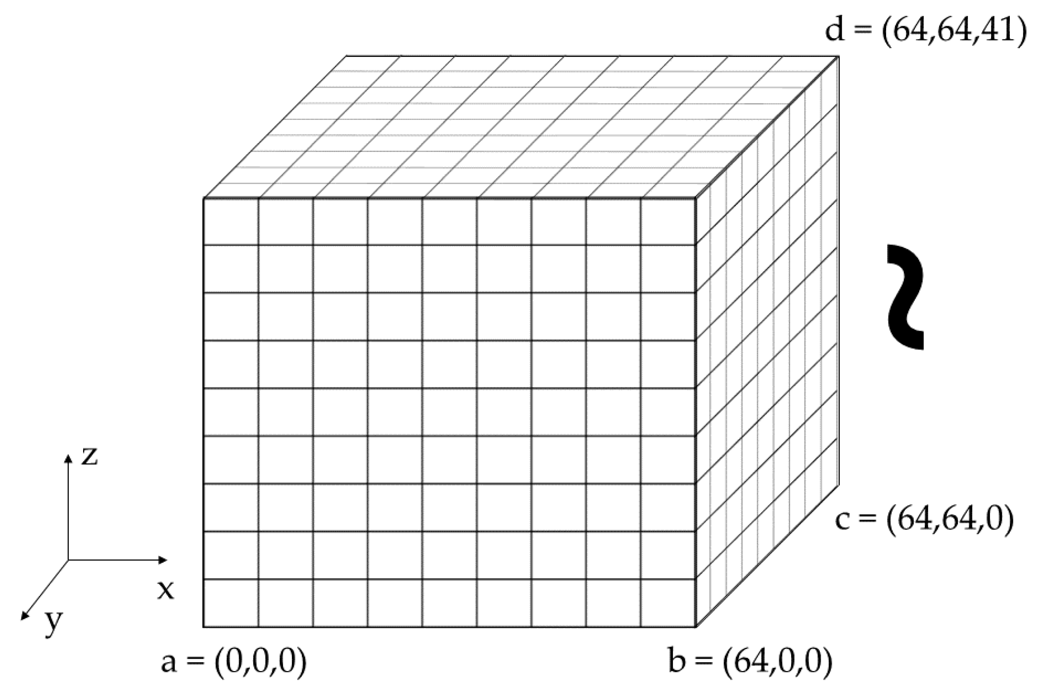
Note that the target material in the simulation is Hf0.4Zr0.6O2 and the corresponding simulation parameters are summarized in Table 1. In this work, we considered the Neumann boundary at the side of the 2D and the 3D structures (i.e., the edge values were not fixed). The mechanical boundary condition was obtained from the clamped boundary condition [24], and was not allowed to deform. Therefore, the strain is zero. Polarization at the outside of the structures is not allowed (which represents a limit of this study). To initialize the structure that we considered (see Figure 2), we set the initial values randomly (i.e., Px1 = Py1 = Pz1 = 1/2 × (rand−0.5), where “rand” is a random number between 0 and 1)) when we represented the origin point of the hysteresis loop. However, in the R-FEC circuit simulation, the initial polarization value was set as the maximum value of the polarization (i.e., fully switched).
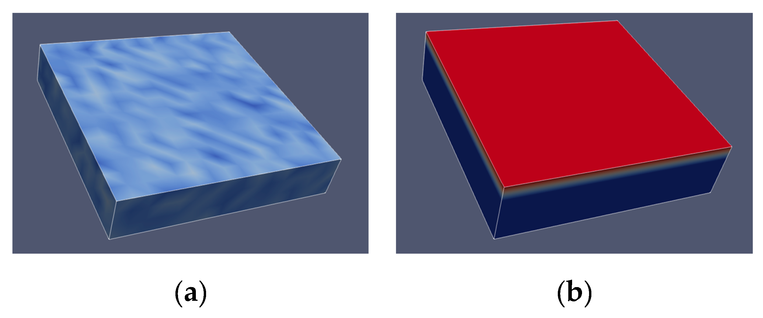
To describe the dynamics of a ferroelectric capacitor, a resistance-ferroelectric capacitor (R-FEC) circuit was built, as shown in Figure 3. Note that the R-FEC circuit was introduced in [14]. When modeling the electrical characteristics of the ferroelectric capacitor, we developed the model for two different structures: the metal-ferroelectric-metal structure (MFM structure) (Figure 4a) and the metal-ferroelectric-silicon (heavily doped silicon) (MFS structure) (Figure 4b). In addition, we inserted a “fixed” interface charge layer between the ferroelectric layer and Si layer; note that the interface trap density (Dit) of 1.4 × 10¹²–5.6 × 10¹² e/cm2) was interpreted as the same amount of electric polarization density.
Using the parameters and setup described above, and 3D phase field simulation (which is based on the TDGL equation), we modeled and simulated the electrical characteristics of the ferroelectric capacitor. The semi-implicit Fourier-spectral method was employed to solve the partial differential equation [26]. The voltage across the ferroelectric capacitor (VFE) can be estimated as:
  V F E = V a p p R I F E = V a p p R V d P z d t d V
where Vapp is the applied voltage, R is an external resistor, IFE is the current across the ferroelectric layer, and V is the volume of the HZO film. In this estimation, the parasitic capacitance parallel to the FEC is assumed to be small enough to be ignored [14]. The value of the resistor was fixed as 800 Ω to amplify the negative capacitance effects, and the volume of the capacitor is 16 × 16 × 10 nm3.

3. Results and Discussion

To investigate the impact of the interface-trapped charge (Qit) in HZO ferroelectric material on the transient response of the R-FEC circuit, various values of trap density in the ferroelectric capacitor ware employed (i.e., ~±1012 e/cm2). If the interface trap density (Dit) is 1012 e/cm2, then it can be translated as the same amount of electric polarization charge (1012 e/cm2~16.02 × 10−6 C/cm2). Note that 1.5 × Dit (1012 e/cm2) ~Pr = 25 × 10−6 C/cm2.
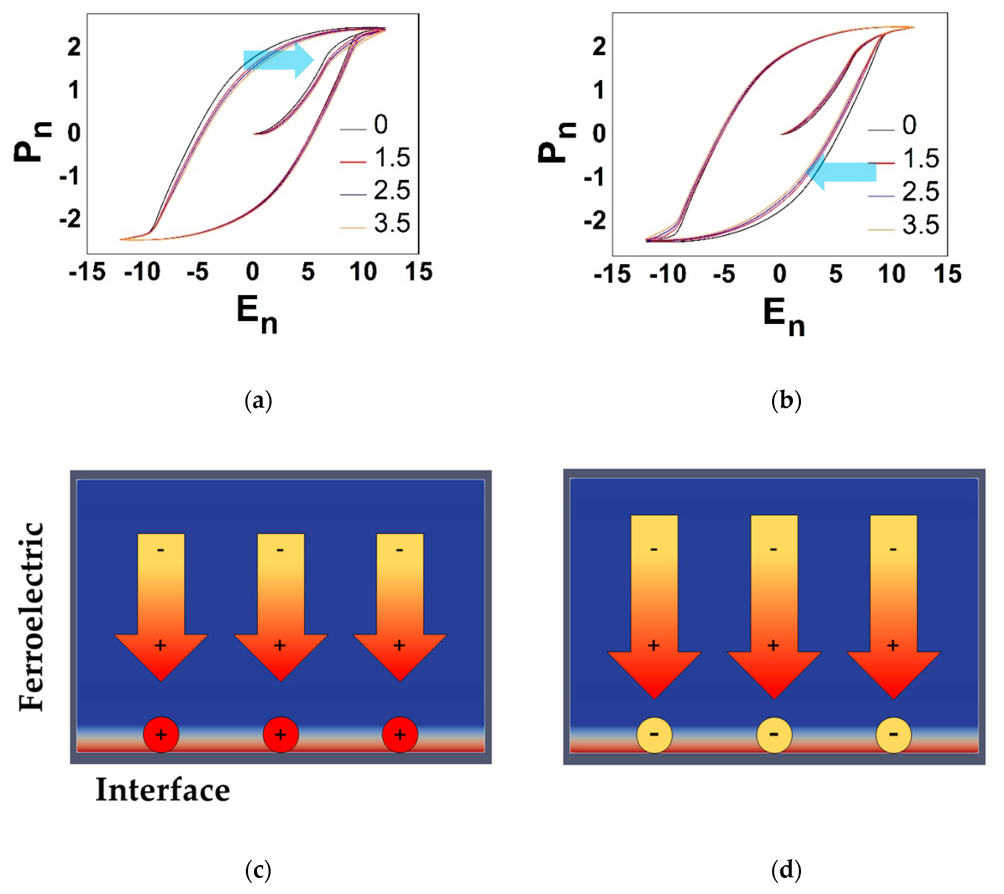
In the 3D phase field simulation, the ferroelectric film is sufficiently thin (<10 nm) that we can assume that the direction of polarization is aligned along the film thickness direction (z-axis). Hence, Px = 0, Py = 0, Pz ≠ 0. In Figure 5, we show the polarization versus electric field (P–E) curve and the polarization versus time (P–t) curve affected by Qit. Herein, Pn is the normalized average value of Pz in the ferroelectric layer, and En is the normalized electric field [25]. In this condition, the hysteresis window is shifted to the right-hand side when Qit is negatively charged. When Qit is positively charged, the hysteresis window moves to the left-hand side.
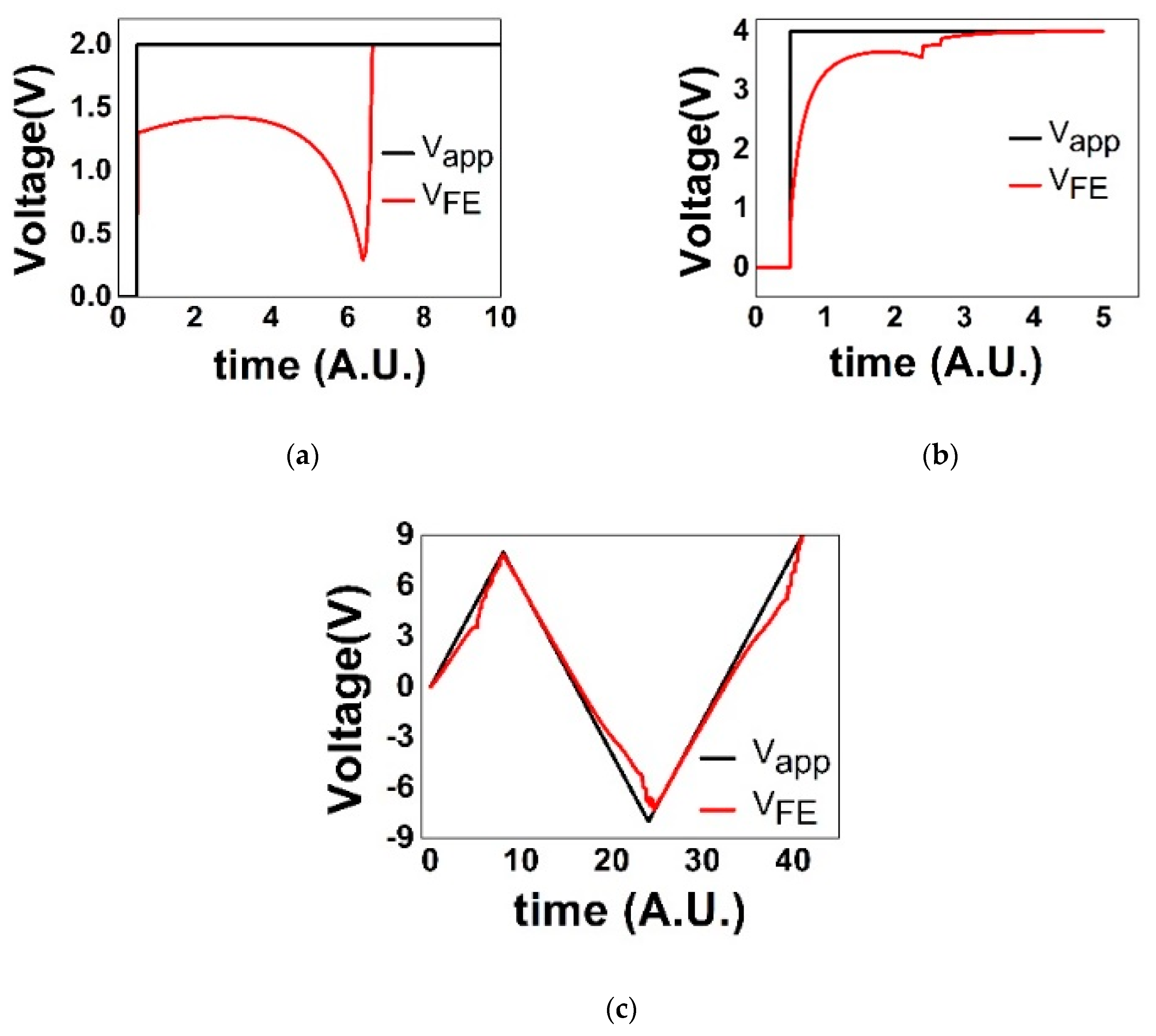
The model developed in this work is valid for ferroelectric material in multiple domains, and clearly shows the transient region of NC (i.e., dQ/dV < 0). Using the developed model, the simulation results (see Figure 6a–c) are comparable with the experimental results in [14,27] and the other simulation results [20,28]. The importance of our 2D simulation result is comparable to the simulation results as mentioned previously. However, the transient negative capacitance effects from the 2D phase field simulation are overestimated because the NC region is too deep (vs. the experimental results as mentioned). Nevertheless, the simulation results clearly aid understanding of the NC effects. Furthermore, due to the addition of an interface trap charge layer on the 3D ferroelectric structure, it is applicable to investigation of the impact of interface traps on the transient NC effect.
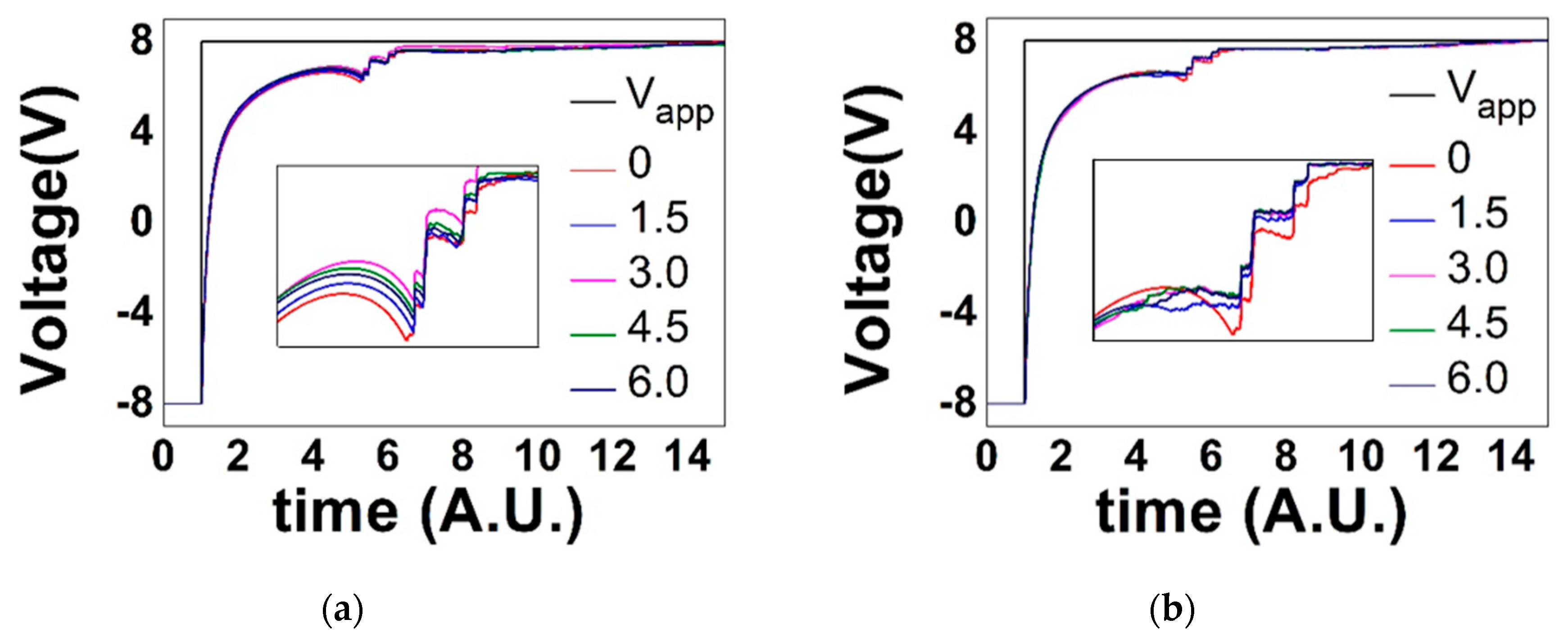
It is noteworthy that the interface trap reinforces the NC region, depending on its charge type (i.e., positively or negatively charged interface trap) (see Figure 7). In Figure 5, the impact of the interface traps is sufficiently small that it shows that the interface trap layer is appropriate to the simulation (note that the number of interface traps per area is 1.4 × 10¹²–5.6 × 10¹² e/cm2, which is close to the ideal minimum value). However, the R-FEC circuit simulation (Figure 7) showed different aspects. Depending on the type of the interface trap, the negative capacitance effects are reinforced or hindered. These results are the main findings of this paper.
The positive charge hinders the polarization switching because the charge repels the polarization. However, the negative charge assists the polarization switching by attraction. Previous research [17] has demonstrated that NC behavior in a multidomain model originates from the acceleration of the domain growth. From the understanding of domain growth acceleration in the phase field model, the dominant energy of phase transition (i.e., polarization switching) is gradient energy (domain wall energy). The gradient energy makes the domain wall smoother, so that the domain growth can be accelerated. Figure 7a,b shows several abrupt increases of VFE after the first NC region. The positive interface charge shows that, between the abrupt increases of VFE, the NC region still exists, and is steeper than the neutral one (i.e., without interface trap MFM capacitor). However, the negative interface charge shows that the NC region does not exist or lasts momentarily. Previous research [29] has demonstrated that NC behavior in interface (ferroelectric-dielectric) trap charge injection causes reverse switching, and thereby leads to the NC effects.
Considering these physics, for the NC effect in multidomain ferroelectric materials, the gradient energy dominance leads to NC behavior, and the positive interface charge (the opposite direction of switched polarization) can increase the duration time of the gradient energy dominance, thus increasing the NC region. On the contrary, the negative interface charge assists the polarization switching, so that the charge reduces the gradient energy dominance, and therefore, the switching is faster due to its attraction. Thus, the duration time of gradient energy dominance is shorter, and therefore, the dominance weakens.

4. Conclusions

We investigated the effect of the interface-trapped charge on the transient negative capacitance in a ferroelectric capacitor (Hf0.4Zr0.6O2) connected in series with an external resistor. A 3D phase field model was used to analyze the electrical behavior of the NC effect with interface-trapped charge (±Qit in the range of 1.4 × 10¹²–5.6 × 10¹² e/cm2) in metal-ferroelectric-silicon (heavily doped Si). The interface trap reinforces or hinders the negative capacitance effects, depending on its charge type (positive or negative). Moreover, gradient energy (domain wall energy) dominance during polarization switching can cause a negative capacitance effect. Based on the concept discussed in this work, the process of deposition should take the impact of interface charge into account in the manufacture of a NC-MOSFET with an MFS gate stack structure. If the charge type of the interface trap can be controlled, a positively charged interface trap is preferable considering the switching performance of the NC-MOSFET. Moreover, the type of interface trap charge helps elucidate the physical origin of negative capacitance effects.

Author Contributions

Conceptualization, T.K. and C.S.; methodology, T.K.; software, T.K.; validation, T.K. and C.S.; formal analysis, T.K.; investigation, T.K.; resources, T.K.; data curation, T.K. and C.S.; writing—original draft preparation, T.K.; writing—review and editing, C.S.; visualization, T.K.; supervision, C.S.; project administration, C.S.; funding acquisition, C.S. All authors have read and agreed to the published version of the manuscript.

Funding

This work was supported by the National Research Foundation of Korea (NRF) grant funded by the Korea government (MSIP) (No. 2020R1A2C1009063, 2020M3F3A2A01082326, 2020M3F3A2A01081672, and 2020M3F3A2A02082473). This work was also supported by the Future Semiconductor Device Technology Development Program (10067746) funded by the Ministry of Trade, Industry & Energy (MOTIE) and the Korea Semiconductor Research Consortium (KSRC).

Conflicts of Interest

The authors declare no conflict of interest.

References

  1. Moore, G. Cramming More Components onto Integrated Circuits. Proc. IEEE 1998, 86, 82–85. [Google Scholar] [CrossRef]
  2. Lee, C.; Ko, E.; Shin, C. Steep Slope Silicon-On-Insulator Feedback Field-Effect Transistor: Design and Performance Analysis. IEEE Trans. Electron Devices 2018, 66, 286–291. [Google Scholar] [CrossRef]
  3. Park, J.; Shin, C. Tunnel Field-Effect Transistor with Segmented Channel. IEEE J. Electron Devices Soc. 2019, 7, 621–625. [Google Scholar] [CrossRef]
  4. Ko, E.; Shin, J.; Shin, C. Steep switching devices for low power applications: Negative differential capacitance/resistance field effect transistors. Nano Converg. 2018, 5, 1–9. [Google Scholar] [CrossRef] [PubMed] [Green Version]
  5. Cho, K.; Shin, C. Simulation Techniques for Nanoelectromechanical (NEM) Relay. J. Nanosci. Nanotechnol. 2018, 18, 6615–6618. [Google Scholar] [CrossRef] [PubMed]
  6. Ko, E.; Shin, J.; Shin, C. Steep Slope Silicon-on-Insulator Field Effect Transistor with Negative Capacitance: Analysis on Hysteresis. J. Nanosci. Nanotechnol. 2019, 19, 6128–6130. [Google Scholar] [CrossRef] [PubMed]
  7. Salahuddin, S.; Datta, S. Use of Negative Capacitance to Provide Voltage Amplification for Low Power Nanoscale Devices. Nano Lett. 2008, 8, 405–410. [Google Scholar] [CrossRef]
  8. Yadav, A.K.; Nguyen, K.X.; Hong, Z.; Garcia-Fernandez, P.; Aguado-Puente, P.; Nelson, C.T.; Das, S.; Prasad, B.; Kwon, D.; Cheema, S.; et al. Spatially resolved steady-state negative capacitance. Nat. Cell Biol. 2019, 565, 468–471. [Google Scholar] [CrossRef] [Green Version]
  9. Hoffmann, M.; Pešić, M.; Slesazeck, S.; Schroeder, U.; Mikolajick, T. On the stabilization of ferroelectric negative capacitance in nanoscale devices. Nanoscale 2018, 10, 10891–10899. [Google Scholar] [CrossRef] [Green Version]
  10. Zubko, P.; Wojdeł, J.C.; Hadjimichael, P.Z.M.; Fernandez-Pena, S.; Sené, A.; Luk’Yanchuk, A.S.I.; Triscone, S.F.-P.J.-M.; Íñiguez, J.C.W.J. Negative capacitance in multidomain ferroelectric superlattices. Nat. Cell Biol. 2016, 534, 524–528. [Google Scholar] [CrossRef] [Green Version]
  11. Yuan, Z.C.; Rizwan, S.; Wong, M.; Holland, K.; Anderson, S.; Hook, T.B.; Kienle, D.; Gadelrab, S.; Gudem, P.S.; Vaidyanathan, M. Switching-Speed Limitations of Ferroelectric Negative-Capacitance FETs. IEEE Trans. Electron Devices 2016, 63, 4046–4052. [Google Scholar] [CrossRef]
  12. Sharma, P.; Zhang, J.; Ni, K.; Datta, S. Time-Resolved Measurement of Negative Capacitance. IEEE Electron Device Lett. 2018, 39, 272–275. [Google Scholar] [CrossRef]
  13. Cheng, C.-H.; Chiu, Y.-C.; Liou, G.-L. Experimental Observation of Negative Capacitance Switching Behavior in One-Transistor Ferroelectric Versatile Memory. Phys. Status Solidi (RRL) Rapid Res. Lett. 2017, 11. [Google Scholar] [CrossRef]
  14. Hoffmann, M.; Pešić, M.; Chatterjee, K.; Khan, A.I.; Salahuddin, S.; Slesazeck, S.; Schroeder, U.; Mikolajick, T. Direct Observation of Negative Capacitance in Polycrystalline Ferroelectric HfO2. Adv. Funct. Mater. 2016, 26, 8643–8649. [Google Scholar] [CrossRef]
  15. Park, H.W.; Roh, J.; Bin Lee, Y.; Hwang, C.S. Modeling of Negative Capacitance in Ferroelectric Thin Films. Adv. Mater. 2019, 31, e1805266. [Google Scholar] [CrossRef]
  16. Saha, A.K.; Gupta, S.K. Multi-Domain Negative Capacitance Effects in Metal-Ferroelectric-Insulator-Semiconductor/Metal Stacks: A Phase-field Simulation Based Study. Sci. Rep. 2020, 10, 1–12. [Google Scholar] [CrossRef]
  17. Smith, S.; Chatterjee, K.; Salahuddin, S. Multidomain Phase-Field Modeling of Negative Capacitance Switching Transients. IEEE Trans. Electron Devices 2018, 65, 295–298. [Google Scholar] [CrossRef]
  18. Sluka, T.; Mokry, P.; Setter, N. Static negative capacitance of a ferroelectric nano-domain nucleus. Appl. Phys. Lett. 2017, 111, 152902. [Google Scholar] [CrossRef]
  19. Yoon, C.; Choe, K.; Shin, C. Energy-Delay Sensitivity Analysis of a Nanoelectromechanical Relay with the Negative Capacitance of a Ferroelectric Capacitor. IEEE J. Electron Devices Soc. 2020, 8, 365–372. [Google Scholar] [CrossRef]
  20. Shin, C. Experimental understanding of polarization switching in PZT ferroelectric capacitor. Semicond. Sci. Technol. 2019, 34. [Google Scholar] [CrossRef]
  21. Sharma, P.; Tapily, K.; Saha, A.K.; Zhang, J.; Shaughnessy, A.; Aziz, A.; Snider, G.L.; Gupta, S.; Clark, R.D.; Datta, S. Impact of total and partial dipole switching on the switching slope of gate-last negative capacitance FETs with ferroelectric hafnium zirconium oxide gate stack. In Proceedings of the 2017 Symposium on VLSI Technology, Kyoto, Japan, 5–8 June 2017. [Google Scholar]
  22. Chen, L.; Shen, J. Applications of semi-implicit Fourier-spectral method to phase field equations. Comput. Phys. Commun. 1998, 108, 147–158. [Google Scholar] [CrossRef]
  23. Yang, W.; Chen, L.-Q. Computer Simulation of the Dynamics of 180o Ferroelectric Domains. J. Am. Ceram. Soc. 1995, 78, 2554–2556. [Google Scholar] [CrossRef]
  24. Chen, L.-Q. Phase-Field Method of Phase Transitions/Domain Structures in Ferroelectric Thin Films: A Review. J. Am. Ceram. Soc. 2008, 91, 1835–1844. [Google Scholar] [CrossRef]
  25. Saha, A.K.; Ni, K.; Dutta, S.; Datta, S.; Gupta, S.K. Phase field modeling of domain dynamics and polarization accumulation in ferroelectric HZO. Appl. Phys. Lett. 2019, 114, 202903. [Google Scholar] [CrossRef] [Green Version]
  26. Hu, H.-L.; Chen, L.-Q. Three-Dimensional Computer Simulation of Ferroelectric Domain Formation. J. Am. Ceram. Soc. 2005, 81, 492–500. [Google Scholar] [CrossRef]
  27. Khan, A.I.; Chatterjee, K.; Wang, B.; Drapcho, S.; You, L.; Serrao, C.; Bakaul, S.R.; Ramesh, R.; Salahuddin, S. Negative capacitance in a ferroelectric capacitor. Nat. Mater. 2015, 14, 182–186. [Google Scholar] [CrossRef]
  28. Chang, S.-C.; Avci, U.E.; Nikonov, D.E.; Manipatruni, S.; Young, I.A. Physical Origin of Transient Negative Capacitance in a Ferroelectric Capacitor. Phys. Rev. Appl. 2018, 9, 014010. [Google Scholar] [CrossRef] [Green Version]
  29. Liu, Z.; Jiang, H.; Ordway, B.; Ma, T.P. Unveiling the Apparent “Negative Capacitance” Effects Resulting from Pulse Measurements of Ferroelectric-Dielectric Bilayer Capacitors. IEEE Electron Device Lett. 2020, 41, 1492–1495. [Google Scholar] [CrossRef]
Figure 1. Polarized ferroelectric layers with an interface trap charge (positively charged). Note that the dark blue arrows represent the polarization intensity, and the interface trap charge is drawn outside the sky blue rectangle. The gray circles represent the charge compensation. (a,b) show the illustrated schematic of polarized ferroelectric film. The thickness of polarized ferroelectric film in (b) is thinner than that in (a), and the reduction ratio of polarization intensity by the interface trap in (b) is higher than that in (a).
Electronics 09 02141 g001
Figure 2. Schematic of the structure of the ferroelectric material used in this simulation. Each value of the corner of the cube a, b, c, and d is given in a spatial coordinate, and each node of the face has its own spatial coordinate. Each coordinate has three polarization values, Px, Py, and Pz. In this simulation, the cuboid (i.e., ferroelectric film) size is 64 × 64 × 41, and the real space grid is ∆x = ∆y = ∆z = 0.25 nm, so that the ferroelectric film of 16 × 16 × 10 nm3 is reproduced (note that the top layer of the cuboid represents the interface trap charge layer). The two-dimensional simulation was initialized as given above with the exception of dimension of the structure (i.e., 2D rectangular structure).
Electronics 09 02141 g002
Figure 3. A ferroelectric capacitor in series with an external resistor. Vs is an independent voltage source with square-wave voltage pulse, R is an external resistor, iR is the current flowing across R, and CFE is a ferroelectric capacitor.
Electronics 09 02141 g003
Figure 4. Ferroelectric film in a ferroelectric capacitor at an initial state. (a) Ripples in (a) represent the origin point of the hysteresis loop. (b) A fixed interface charge layer is placed on top of the ferroelectric film (note that, in the simulation, the fixed interface charge layer is added to the bottom of the ferroelectric layer). By adding the charged layer, the real Si-ferroelectric interface is reproduced.
Electronics 09 02141 g004
Figure 5. Polarization versus electric field (P–E) curves for the Zr doped HfO2 (HZO) capacitor with or without an interface trap layer: (a) negatively charged interface trap, and (b) positively charged interface trap. Various values of interface trap density are employed (1.5, 2.5, 3.5, i.e., 1.4 × 10¹² C/cm2, 2.34 × 10¹² C/cm2, 3.28 × 10¹² C/cm2, respectively). The polarization (arrow) switching under the positive and negative interface trap (circle) charge is illustrated (see (c,d), respectively).
Electronics 09 02141 g005
Figure 6. Simulated transient negative capacitance (NC) of the R-FEC circuit with different dimensions (2D or 3D) and waveforms (square or triangular). The structure of the ferroelectric capacitor is metal-ferroelectric-metal (MFM): (a) 2D phase field simulation; (b,c) 3D phase field simulation with different waveforms.
Electronics 09 02141 g006
Figure 7. Simulated transient NC of the R-FEC circuit with the interface trap: (a) positive interface trap, (b) negative interface charge. The interface trap density is neutral, 1.4 × 10¹², 2.8 × 10¹², 4.2 × 10¹², 5.6 × 10¹² e/cm2 (0, 1.5, 3.0, 4.5, 6.0, respectively).
Electronics 09 02141 g007
Table 1. Normalized parameters for a resistance-ferroelectric capacitor (R-FEC) circuit [25].
SymbolQuantityValue
a 1 Landau expansion coefficient−1.499
a 11 0.498
a 111 0.001
G 44 Domain coupling parameter1
G 44 1
LKinetic coefficient1
ACapacitor area [nm2]162
Publisher’s Note: MDPI stays neutral with regard to jurisdictional claims in published maps and institutional affiliations.