1. Introduction
The technological development necessitates the smart way of presentation available natural resources. Recently, several countries have executed 5G with high frequency ranges of the spectrum. Sophisticated use of the remaining electromagnetic spectrum perhaps balances the spectral efficiency [
1]. Numerous approaches can be made by directing the high-quality throughput with the prevailing proposed technologies such as In-Band Full Duplex (IBFD). IBFD focus on the efficient utilization of the spectrum for developing a system with better Spectral Efficiency (SE) by the challenging way of spectrum reuse [
2]. The existing performance of 5G mostly based on the Orthogonal Frequency Division Multiple Access (OFDMA) with Half Duplex (HD) due to the high co-channel interference. The 4G scheme is likewise based on OFDMA with HD. The replacement of the existing 4G setup with 5G is comparatively easier and inexpensive. Keeping the consideration of spectrum limitation, it would be better to extend the system further by using INFD for the 5G beyond technologies.
Existing research on FD proves that the use of FD in the transmission doubles the SE of the system. The transmission exchanging mode from HD to FD or vice versa for a Device-to-Device (D2D) communication is one of the approaches for preserving equilibrium between HD and FD [
3,
4]. Beamforming is one of the approaches for FD. A precise design of beamforming for the power allocation management [
5] among the transmitter–relay communication in the cognitive radio networks is appropriate for providing the high rate to a particular near or a distant user. FD, D2D and NOMA communication together deliver improved Ergodic Sum Rate (ESR) compared to HD [
6]. However, the HD outstrips FD at high Signal-to-Noise Ratio (SNR) in the form of outage probability and in the delay-tolerant transmission [
3,
6]. The security is needed in each layer of the communication system. Each layer has dissimilar necessities of security in diverse perspective, due to the parallel motive of multiple associated objects in the 5G beyond technology [
7,
8,
9]. The physical layer security (PLS) is one of the fears in any of the smart arrangement. The connection of multiple devices together, broadcast nature of the system, big data and frequency sharing leads to a big security threat.
There are different types of eavesdropping against the security of a communication system. The eavesdropper (Eve) can be passive or active, contingent on the situation. It can also be between the reliable intended user or a stranger. Present algorithms are considerate for handling the security issues; however, the technological advancement advances the security threats as well. The enactment of the technology everywhere including banks, building, security systems, houses, schools, accounts, industries and transportation makes everything vulnerable. Hybrid eavesdropping (passive eavesdropping on the transmission source and the reactive jamming on legitimate users) in FD-NOMA can be resolved by a method of exhausting eavesdropper by adding cumulative decoding complexity and high energy consumption. It can reduce the effect of jamming and eavesdropping [
10]. Conventional communication system allows dual communication with a transmission and a reception task named the Half Duplex (HD) communication. In HD, the channel is common for dual tasks, with orthogonal (different) time slots or frequency bands (out-of-band FD mode). The simultaneous transmission and reception is possible with the FD communication.
FD permits a device to broadcasts and receives the signals in the same frequency band and time slot. The Out-of-Band FD (OBFD) and the In-Band FD (IBFD) are two types of FD communication system, where the transmission and reception take place together in the same time and frequency slot. IBFD is superior to conventional HD in terms of system reliability, sum rate, network capacity and other theoretical aspects [
11]. FD and D2D communication have common characteristics including better performance at short distances and reduced self-interference at low power transmit signals [
11,
12]. In FD mode, the wireless nodes cannot decode the signals simply. Due to high power difference between devices’ own transmission and the power offered by remote transmit antenna in the received signal, there is eroded Signal Interference (SI) in FD gain. Typically, the transmitted signal is roughly 100 dB higher than the received signal producing eroded Signal Interference (SI) in FD gain. This decreases its capacity level below HD. Conferring the consensus by both academia and industry, it is very problematic to attain SI cancellation/suppression for FD incorporation. The interference reduction is very important factor before putting the FD into practice. The cumulative interference lessens the data rate, latency, secrecy capacity and throughput.
Several approaches have been proposed for the solution of the interference problem: RF digital interference cancellation [
11], advance antennas cancellation and digital base band, channel estimation and power allocation [
13] offers the conceivable answers for FD. Hybrid resources that shift the mode between FD and HD have been developed for emerging the radio resources and simultaneously enlightening the SE. Separated resources are needed such as antennas for the distinct transmission with the least possible interference. If the devices are too close, then this can be a waste of using frequency band, especially if the data for communication are massive. The use of additional devices such as a relay may also increase the system complexity. Therefore, it has been observed that D2D communication is reliable when devices are close. It is possible for the BS to grant approval for device-to-device communication in the same cell only. When the D2D distance increases, the throughput decreases significantly. FD can improve the traditional wireless communication to a better extent in terms of loss of data due to high congestion, hidden terminals, time delay and SE. The key idea behind the usage of FD communication is to make heterogeneous dense network with high capacity and flexible relaying modes. The quantitative analysis of theoretical and practical placement shows that, at the cost of enlarged complexity, FD provides diversity, high throughput, low symbol error rate and decreased use of HD. The D2D FD communication becomes better with the increase of in-cell communication ratio that provides to bandwidth efficiency.
The IBFD distribution desires new algorithms for the arrangement of 5G beyond technology. It goals to usage the high frequency bands such as millimeter waves (mmWaves). This is for the low frequency spectrum in fully used with the present system of below 5G technologies. Additionally, several wireless devices are being used in the communication system which cannot be charged using the traditional wired power system. Such devices also contain a limited amount of power that can exhaust rapidly. This situation brings the attention towards renewable energy resources, Wireless Information Transfer (WIT) and Simultaneous Wireless Information and Power Transfer (SWIPT) [
14]. To prolong the life of such kind of wireless devices in Full Duplex Relay (FDR) systems, several research articles consider RFEH [
9]. There exist several literature works proposing various SWIPT architecture such as ideal receivers, Power Splitting (PS) receivers and Time Switching (TS) receivers [
15]. Only PS and TS are applicable practically. In PS, the receiver splits the power for RFEH and transmission of signal, and, in TS, the receive uses two time slots to harvest and retrieve information. Several new approaches and algorithms have been attempted for more accurate RFEH. A realistic measurement and waveform-based energy harvesting model [
16] uses the pre-equalization to prevent wireless channel distortion. The result shows that using the phase modulation the power conversion efficiency is increased by a factor of two. FD with bidirectional wireless sensor network (BWSN) and Multiple Input Multiple Output (MIMO) based SWIPT system [
17] is a considered approach for harvesting energy and transmitting power constraints with a joint optimization problem for source and relay beamforming. Optimization for MIMO-NOMA [
18] with dynamic power allocation and user grouping provides an effective way for SWIPT. For the secure transmission in mind self jamming, SWIPT [
19] may provide security along with energy harvesting.
1.1. Motivation and Contribution
The requirement for the innovative spectrum consumption in a diligent way with least interference and high security in 5G leads towards the motivation to develop a system for IBFD with least interference. After reviewing the literature based on IBFD, a space of interference management and security issues is observed for 5G. To target the complexity of interference and security issues of a FD system, we propose a new component and forward FD scheme.
For achieving the desired objectives, the contributions of this paper are:
A component-forward cooperative communication is proposed to minimize the possibility of interference in IBFD with D2D, AN and modulation-based interference reduction [
1].
Artificial Noise (AN) is added to prevent the increasing security threats for the proposed FD component-forward (FD-CF) cooperative communication system. The AN increases the interference at the Eve’s node and declines the possible material decoding. It also drains Eve by providing high computational complexity and energy.
The aforesaid approaches are used for refining the system’s secrecy capacity, outage probability and throughput.
Alongside the basic system, RFEH is also used to further elaborate the proposed scheme with secrecy capacity, outage probability and throughput in the presence of a TS based RFEH circuit.
The idea is elaborated with the difference between the FD-DF and FD-CF in
Table 1. In this paper, we use one of the baseline FD-DF techniques with a single relay selection from
K relays [
20] for the comparison with FD-CF in the simulation result. The proposed idea can be implemented with any of the existing FD-DF techniques to obtain the same differences.
1.2. Structure
The structure for the rest of the paper is as follows.
Table 2 lists the abbreviations used in the paper.
Section 2 provides the proposed system model details with the description of proposed FD-CF and addition of AN.
Section 3 contains the computation of secrecy capacity, secrecy outage probability, harvested power and system throughput.
Section 4 shows the numerical results for the comparison of FD-CF and FD-DF schemes followed by conclusion in
Section 5 and
Appendix A.
2. System Model
Figure 1 represents the system model for a D2D component-forward supported IBFD (FD-CF) for a Downlink (DL) wireless cooperative communication system. The system can be enabled in any other scenario as well. However, this paper focuses on the basic system model of FD-CF. The offered system model includes a source (Alice), receiver (
Bob), IBFD enabled relays
for
and the passive eavesdropper (Eve).
Bob and Eve are considered to have similar channel conditions. Alice,
Bob and Eve contain a single antenna excluding relays.
is the total power for each transmission, which is divided equally for Alice–relay and relay–
Bob transmission. Alice–relay and relay–
Bob distances are considered to be equal,
. The distance can be varied according to the system model requirements. As per assumption, relay and
Bob are facing a Rayleigh fading channel and their Channel State Information (CSI) is considered to be known by Alice, relay and
. Eve is considered not to have the CSI information of the legitimate user. Eve’s channel is considered to be the same as
Bob,
. Therefore, Eve is capable of detecting the signal of
.
and
are the other channels for the component-forward cooperative transmission in the IBFD mode from Alice to relay and the SI channel from relay to itself.
Alice uses the algorithm used in [
1,
21], which is basically a technique for reduction of interference in Non-Orthogonal Multiple Access (NOMA), for the superposition of the signals, as it prevents the signal from interference as compared to conventional techniques due to the orthogonal nature of modulated signals. The interference in [
1,
21] is half as compared to conventional NOMA because half of the receivers are modulated on the real component and the remaining are modulated on the quadrature components of the modulation. Ideally, there will be no interference between the receivers’ signal modulated on the perpendicular component. This paper does not include the NOMA system. However, the basic idea of [
1] is used to balance the offered interference of the proposed FD-CF algorithm. FD-CF can also be extended for NOMA in future work.
FD-CF is an algorithm in which the source (Alice) encodes the transmission message on the real component of the modulation only and add a complex AN with the signal which is a null space of the receiver’s channel (relay(s)). The relay selection takes place according to [
20]. The selected relay from the
K relays receives the real component of the signal only, as AN has been nullified already from its channel. After receiving the signal, relay modulates the signal on the quadrature component of the modulation, adds AN which is null space of
and forwards it without decoding. Relay receives the real component signal and forwards the quadrature component of the signal. Therefore, ideally, there is no co-channel interference, which is the main problem in IBFD transmission.
According to the system model, the IBFD mode relay receives signal of the intended to assist the with component-forward cooperative communication. Relay modulates the signal on quadrature component, adds AN and null space of and forwards the signal of without decoding it, using component-forward to assist . The addition of prevents any other receiver from correctly decoding the signal intended for . Relay receives a signal modulated on real component and it forwards the signal after modulating it on the imaginary component with the power . There is a self-interference at the FD mode between the real component of the received signal by the relay and the complex added in the signal forward by the relay.
For RFEH circuit in the given system model, TS is used for harvesting energy. Relay decodes the signal from Alice in time and harvests energy. Now, relay carries the signal and harvested energy which was received already in the previous transmission. In the second time slot , relay receives the signal from Alice and forwards the previously decoded signal by using the harvested power to within the same time and frequency band.
2.1. Addition of Artificial Noise for Better Security
Artificial Noise (AN) is a sufficient way for the protection of the transmission signals from an Eve and other users. AN system design depends on the receiver’s channel but not the Eve’s channel. AN is generated, before transmission of signal by the Alice and the relay to degrade the Eve’s channel. The AN
is complex Gaussian in nature. In the case of the fixed AN, the value of
might be smaller. To avoid this situation, the value of AN is considered as the Gaussian random variable in the null space of
of the relay’s and
Bob’s channels, respectively, such that
[
22]. The superposed signal on the Alice’s node for the broadcast can be given as
In the above equation, the signal does not have the complex nature. However, it is combined with the AN
to make the total complex signal. For more than one users, some users’ signals can be modulated on imaginary and some on the quadrature component of the modulation to make a complete complex signal for transmission. In this paper, the use of AN makes the total complex transmission signal. Additionally,
is added by Alice as a null space of the relay and relay added
as the null space of
. The superposed signal for broadcast on the relay’s node is given as
2.2. System Analysis
The relay and
decodes the signal normally as in a normal communication system. However, Eve cannot decode the signal received from Alice or the relay due to the addition of AN, which is the null space of the channel
and
of the relay and
only. The signal received by
also includes the self-interference for its co-channel transmission as [
20]:(1);
where
is the Additive White Gaussian noise (AWGN) and
is the signal transmitted by relay (received along with the previous transmission) to the
in the FD mode, which causes self-interference.
The FD cooperative communication is used for
due to no direct link between Alice and
. The total DL received signal by
from the relay is given in [
20]:(5),
In the above equation, the signal received from the relay contains only the imaginary part, as .
Eve’s received signal can be determined by adding AN [
22]
in Equation (
4). Eve receives signal with interference due to lack of information about AN.
4. Numerical Results
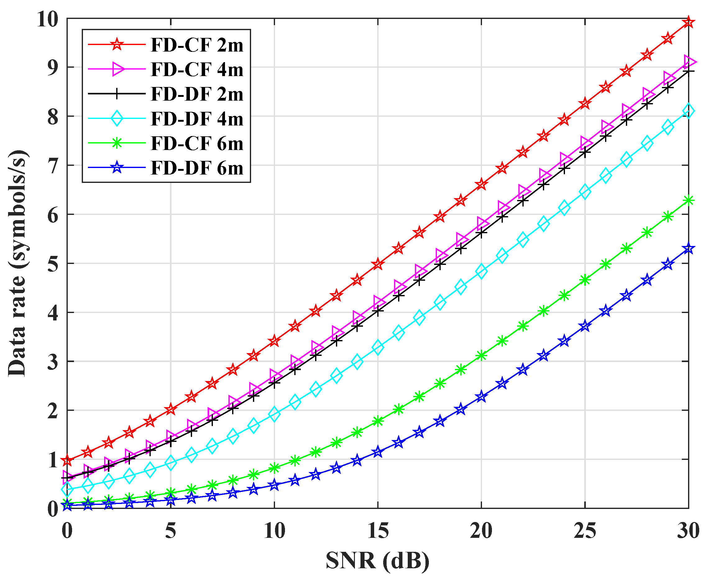
In this section, we discuss the simulated results comparison between the proposed FD-CF and FD-DF cooperative communication system. For the simulation of the systems’ comparison, Rayleigh flat fading channel and 16-QAM was considered. Other numerical values that were used for the simulation are given as: = 0.5 m, = 0.5 m, = 2, = 1 m, = 1 W, = 0.5 W and = 0.5 W. MATLAB was used as a simulation tool for the comparison between the proposed and the baseline scheme.
For the fair comparison between FD-CF and FD-DF, all selected parameters were same including AN. The only difference was the interference level during the IBFD mode in both techniques.
Figure 2 shows the simulation result of the achievable data rate of the FD-CF and FD-DF K relay(s) system. For this particular simulation, the distance was changed from 0.5 to 2, 4 and 6 m. However, the same power was used for a fair comparison. It shows that the achievable data rate decreases with the increase of distance. However, the performance can be maintained by increasing the amount of power respectively. The proposed FD-CF system outperforms FD-DF system. This is due to the comparatively less interference in the proposed FD-CF system. The opposite components reduces the chance of interference.
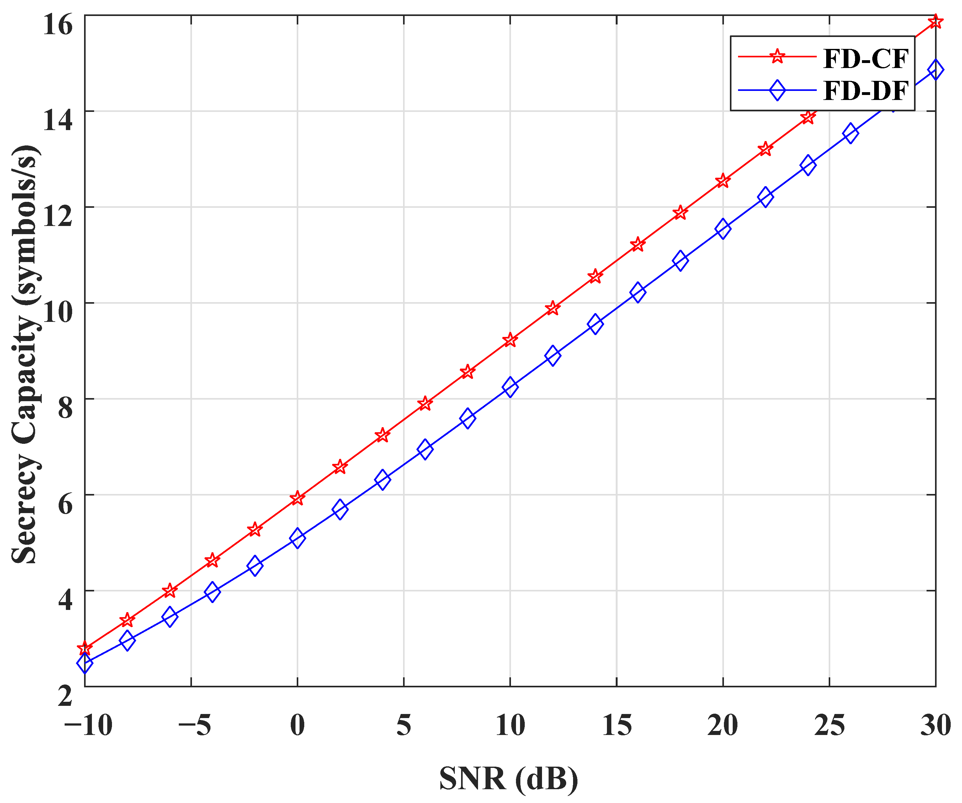
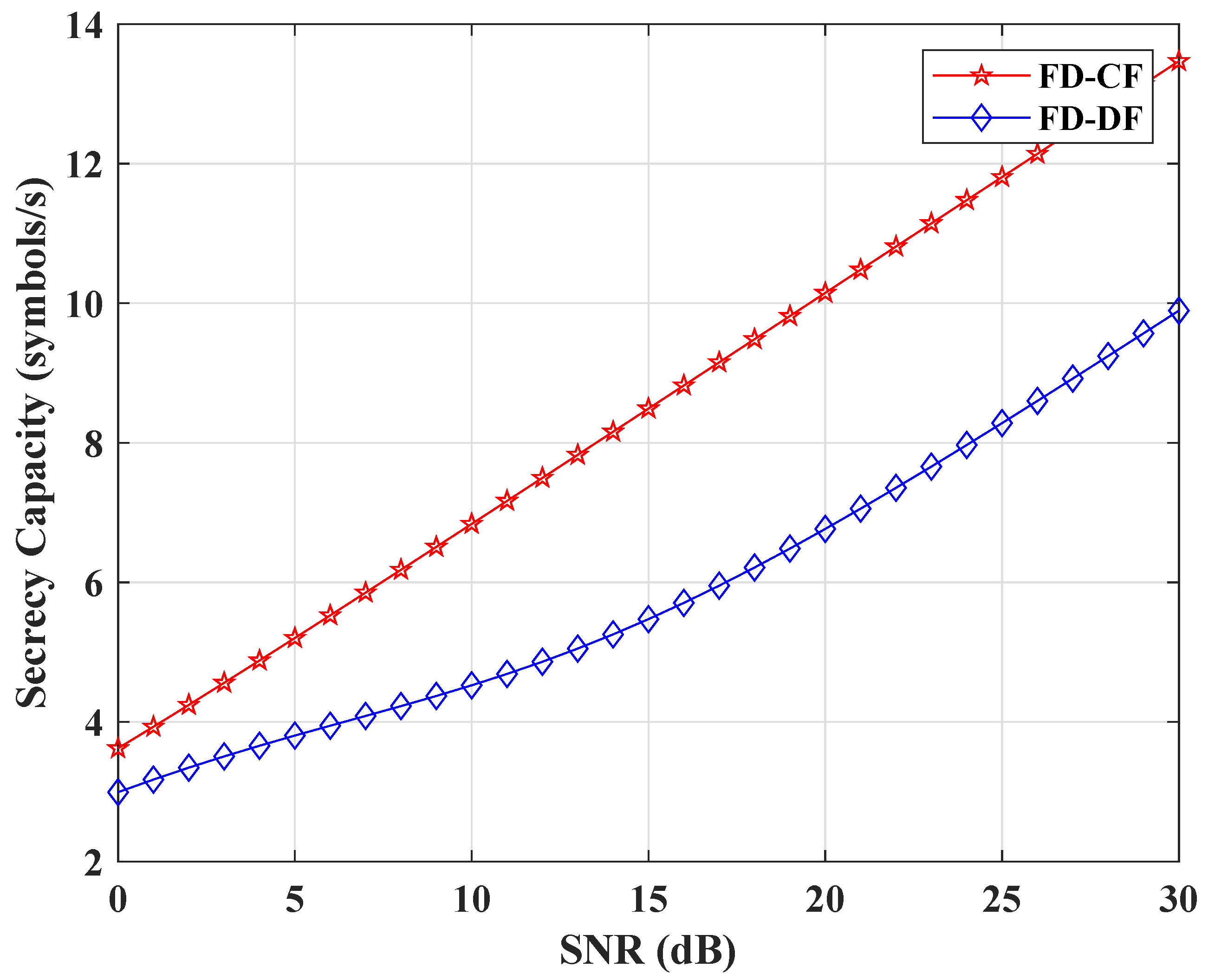
Figure 3 and
Figure 4 show the secrecy capacity comparison with respect to the respective SNR. In
Figure 3, the transmitted powers of Alice
and the relay
are same. In
Figure 4, the relay uses harvested power
for forwarding the signal of
. It is clear from both figures that the secrecy capacity of both FD-CF and FD-DF is increasing with time. However, the secrecy capacity for FD-CF is higher as compared to FD-DF. This is due to the less interference at the relay by the FD-CF scheme and the high introduced interference at the Eve’s node.Therefore, the proposed FD-CF outperforms FD-FD.
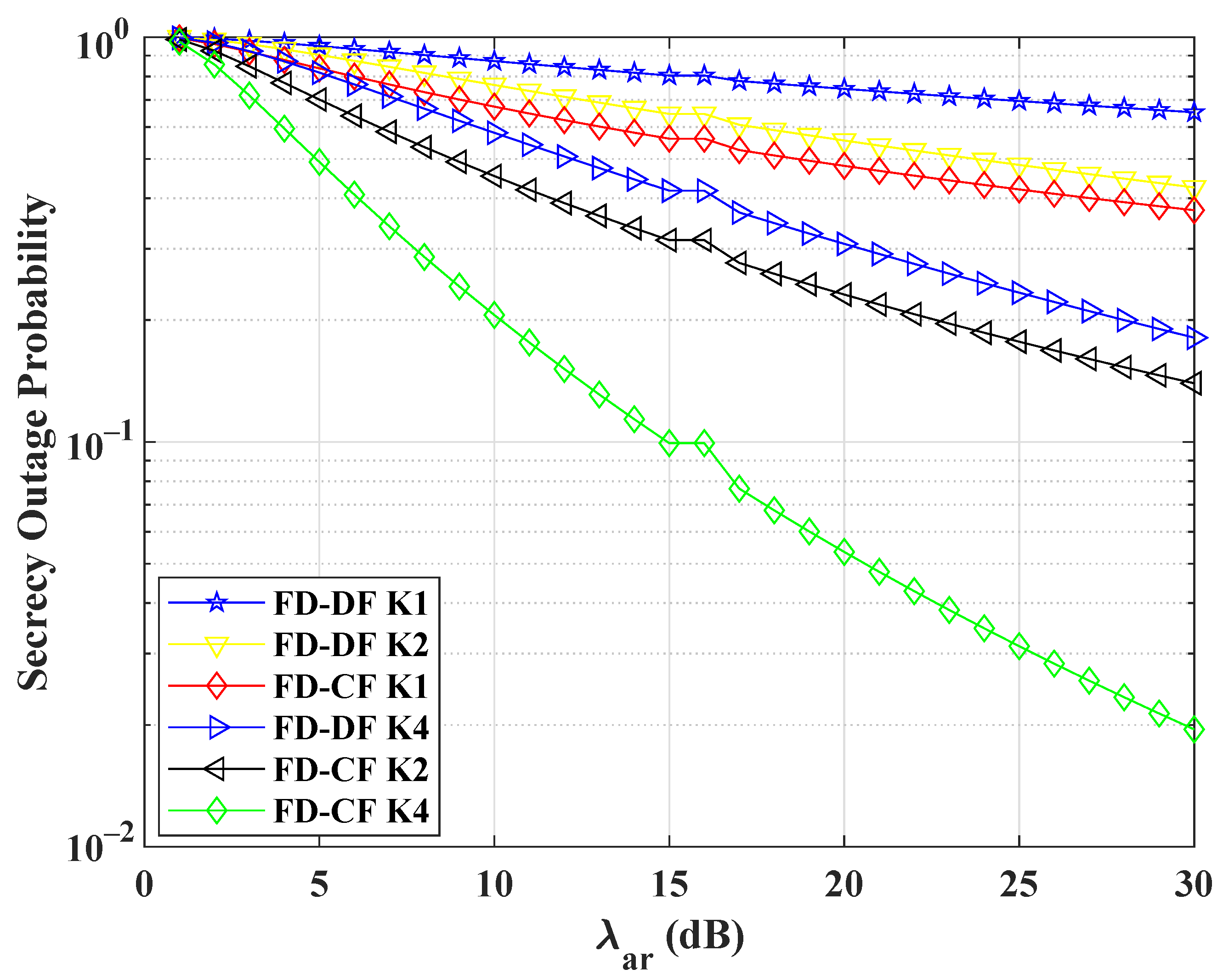
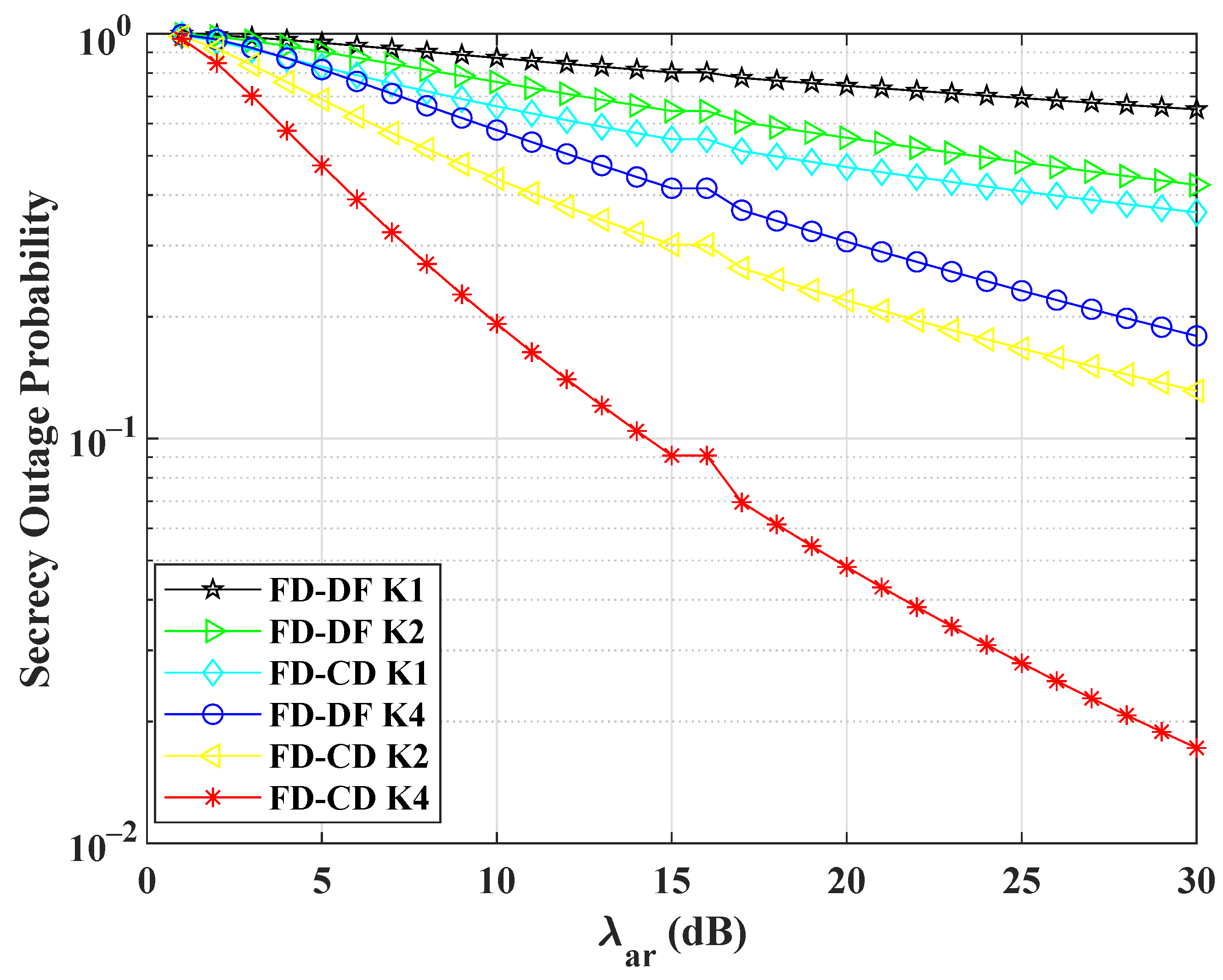
Figure 5 and
Figure 6 show the comparison for the secrecy outage probability offered by FD-DF and FD-CF. In
Figure 5, the transmitted powers of Alice
and the relay
are the same. In
Figure 6, the relay uses harvested power
for forwarding the signal of
. To show the different response with respect to the number of relays
K, we simulated the results for
. SOP result for both algorithms decreases with the increase of SNR. However, FD-CF outperforms FD-DF, due to the same reason discussed of minimum interference as discussed for the simulation results above. For the proposed technique the
is approximately equal to 0 due to high interference at Eve. According to the derived equation of outage probability
must be greater than zero. Therefore, for simulation purposes, we considered
for FD-CF.
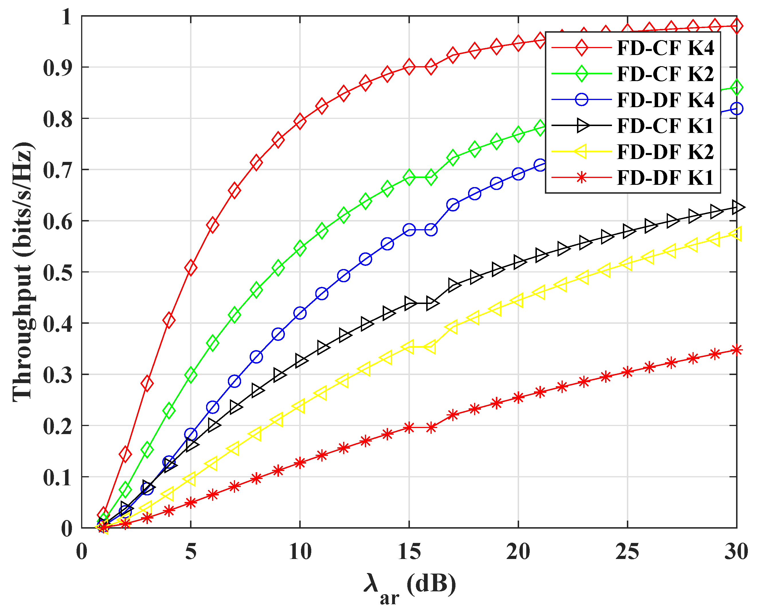
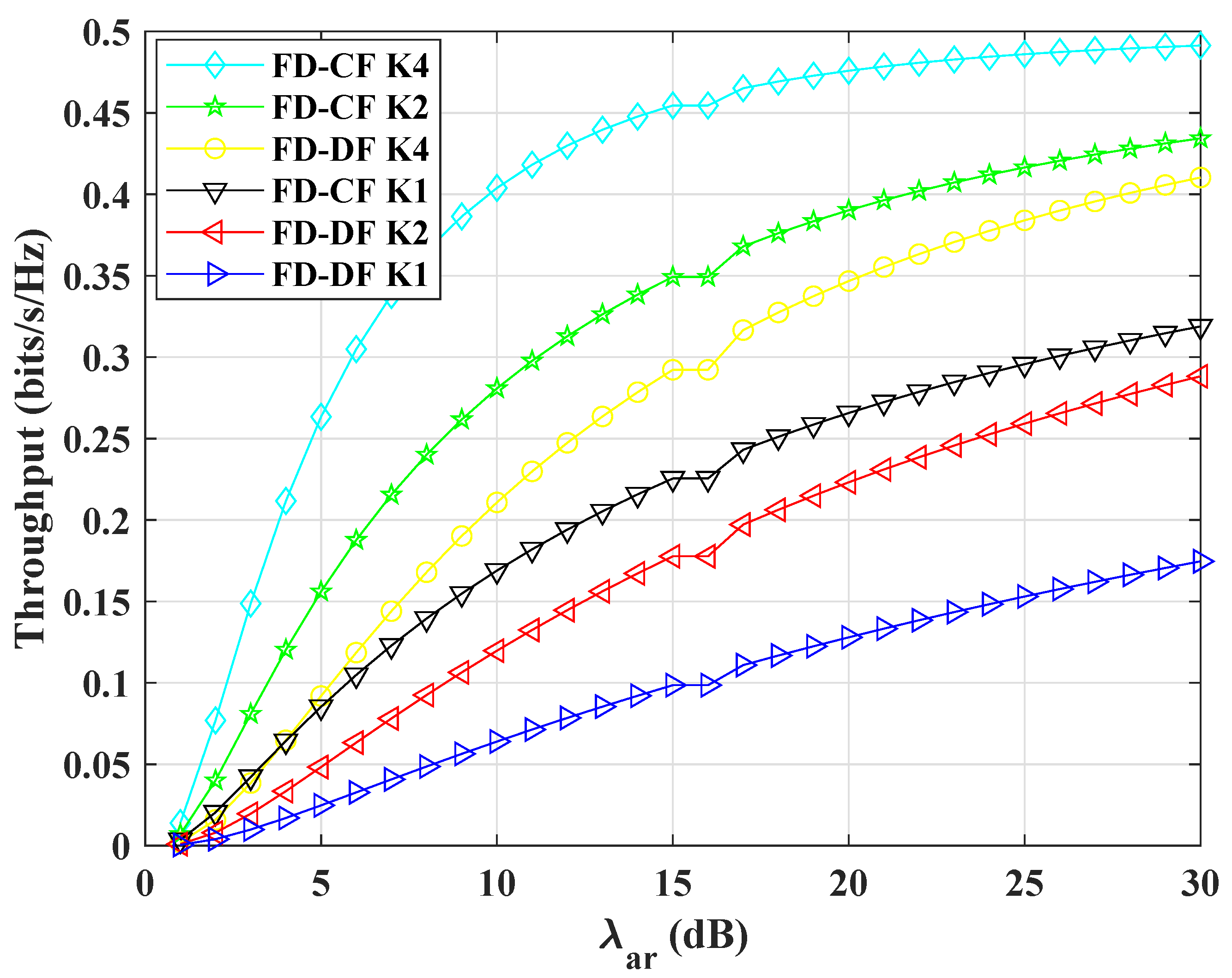
Figure 7 and
Figure 8 show the increasing throughput with SNR for FD-DF and FD-CF schemes. To show the different response with respect to the number of relays
K, we simulated the results for
. Throughput of FD-CF is higher due to its low SOP as compared to FD-DF algorithm. It can be seen in figures that with
the throughput is maximum. The level of throughput decreases with the reduction in the number of relay(s) selection. In addition, the proposed FD-CF with
outperforms FD-DF with
Minimum interference in FD-CF makes it reliable comparatively.
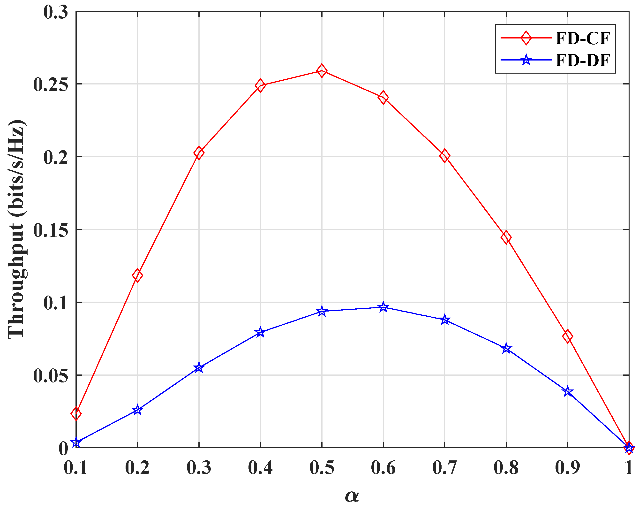
Figure 9 shows the throughput change with respect to
. FD-CF throughput is better than FD-DF. Clearly, the throughput for both techniques first increases and then decreases with the increase of time switching ratio. When the time switching ratio is maximum, the throughput for both schemes is zero. It means that the entire available time is used for harvesting power and not for any transmission. It can be concluded with this result that the throughput can be maximize by allocating suitable
for harvesting power.


