Smart Grid Virtualisation for Grid-Based Routing

 ,
,
Abstract
1. Introduction
2. State of the Art
2.1. Smart Grid Communication Networks
- the required quality of service (QoS) in order to prioritise and assure the delivery of critical traffic,
- reliable communication even if parts of the network fail, data security and privacy as well as resiliency against attacks, and
- scalability and availability even in remote locations.
2.2. Developments and Trends in Smart Grids
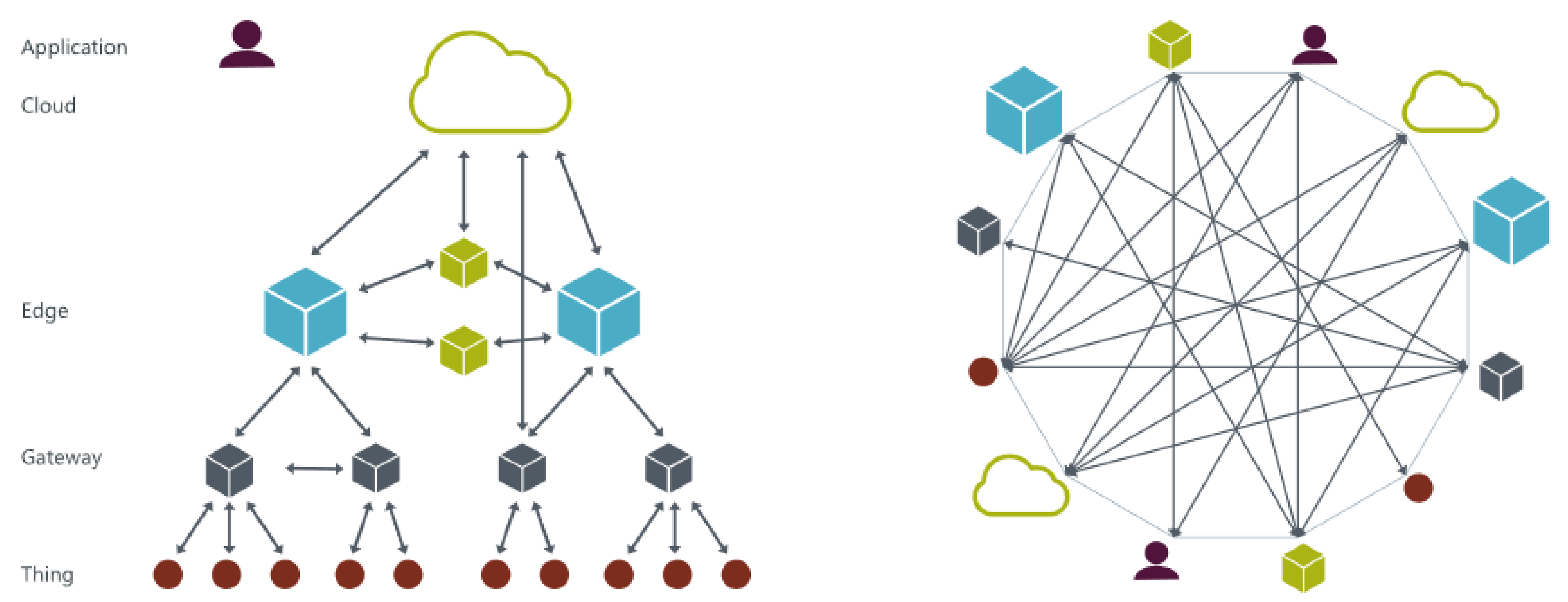
- Edge Computing: Real-time data or data with highly sensitive information is processed and distributed only locally (e.g., within a closed/islanded group of communication nodes, determined by the instantaneous grid state) while other data are transmitted to the cloud for further processing and operation, not demanding the criteria stated above.
- Data follows device: Telemetry data are displayed on a mobile device, handheld or augmented reality device. For example: According to the geographic location of the worker, the device displays useful information dependent on the task (e.g., maintenance, commissioning, analysis) and based on the field devices nearby.
- To circumvent the shortcomings of SCADA systems stated above, computations and decisions will be made decentrally. Thus, data has to be distributed to components that are allowed to receive the data to which it has relevance.
- Mass rollout of IoT devices: With the proliferation of IoT and industrial internet of things (IIoT) devices for metering, the number of these devices will challenge network operators as well as conventional SCADA systems. On one hand, these devices have to communicate with other devices in a secure way without revealing information to the outside world, on the other hand, the configuration effort has to be minimised. Thus, frameworks or systems which can manage a high number of communication endpoints are highly demanded.
- Self-adaptivity of future power systems (such as automated changes of the power grid topology regarding which loads are connected to which generators) might require dynamic interactions between the components of the electrical infrastructure and the ICT infrastructure. This leads to the requirement of programmable networking.
- Agent-based information distribution: Agent-based approaches are commonly described as self-adaptive, flexible, and scalable, which includes the ability to dynamically adapt the interactions (data exchanges) between individual agents. A flexible communication system could support this by directly controlling data distribution corresponding to current needs. For instance, in a multi-agent-system (MAS), an observer agent might be in the position to control the distribution of information according to the gathered system state (which might be influenced by system-internal or environmental conditions).
3. Example Use Cases
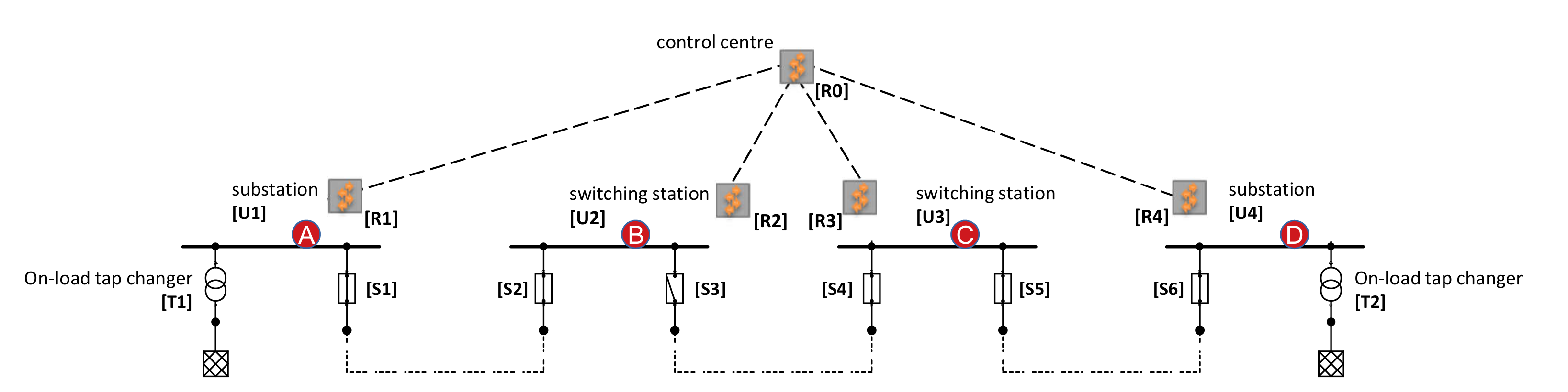
3.1. On-Load Tap Changing Based on Grid State
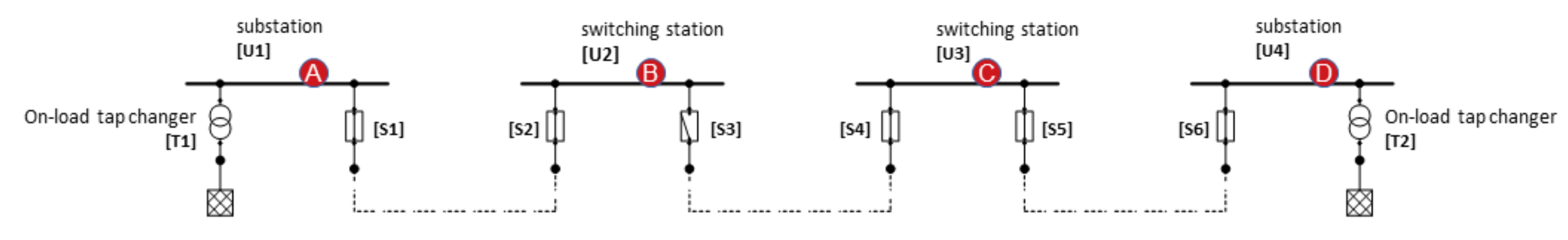
3.2. Delimiting Outages Spatially
- Detection of the outage and receiving information about the fault direction from the protection devices: The information about the fault direction from A, B, C, D is automatically forwarded to the agents in charge for the affected net segment (i.e., the agent controlling the respective switch ). According to the instantaneous grid state (e.g., positions of the switches ) received from other agents in the same grid segment, the agent in charge can delimit and isolate the origin of the fault. In our example, since the direction of the fault at C points to the same direction than at D, it is already clear that the problem is not between C and D; hence, the origin of the problem has to be between C and the open switch at B. Isolation can be performed by opening .
- Detection of the outage without information from the protection devices (but with remote controllable circuit breakers): Since no information about the faulty network segment is available in this case, the agents can delimit the fault region by sequentially disabling net segments and rechecking if there is still a short circuit to be detected at the secondary substation. Since is open, the fault must have occurred somewhere between and . Applying a binary search scheme, we start splitting the network segments at . Since the short circuit detection does not report a problem any more, we can delimit the error to be located between and . Moreover, by opening circuit breaker and again closing , no failure is detected at , so we can deduce that the problem must be located somewhere between and .
3.3. Requirements
- First, the required information needs to be available in the right place and at the right time, which becomes a particularly tough challenge when we assume that communicating elements such as intelligent electronic devices (IEDs), end devices used by service technicians like smart phones, backend servers, or even services built in software only, may continually change their location and need to be supplied with the required information while in transit.
- Second, not only the locations change but also the group of communicating elements change constantly through autonomously interacting agents forming coalitions to solve grid problems with or without the involvement of human operators.
- Third, the ongoing augmentation of the grid with ICT and the continuously developing operational modes require that new applications including software and hardware elements can be easily integrated into the information distribution system without interfering with already established applications.
- R1
- Forwarding of data required for monitoring and control needs to be adapted according to the instantaneous grid state.
- R2
- Flexible and scalable m:n communication is required in order to take into account the potentially large number of communicating elements and changing interconnections.
- R3
- Application-aware traffic separation has to be provided in order to guarantee required communication quality with respect to application requirements and it needs to be agnostic to the currently used communication links and insensitive to brief interruptions.
- R4
- The communication solution has to support a differentiation between critical and non-critical traffic and to avoid interference between different traffic and application types.
- R5
- The communication system should provide information forwarding with particular support for mobile agents and autonomously acting agent coalitions.
- R6
- Information forwarding needs to be highly reliable and must not be affected by changes of the grid state and/or grid topology configuration.
- R7
- A flexible communication system is required to contribute to fast innovation cycles and to make the integration of new devices safe and simple.
- R8
- The communication solution has to support degraded services in case of overload or failure situations.
4. Virtualisation of the Communication Subsystem
4.1. Virtualisation Benefits in the Smart Grid
- Effort for configuration or re-configuration of system components shall be minimised.
- Control tasks shall be redistributed in case of a system downtime (either due to maintenance or outage).
- Situational awareness in case of failures, overload, or deliberate attacks shall be improved.
4.2. Traditional Virtualisation Technologies
4.3. Software-Defined Virtualisation Technologies
4.4. Cloud and Edge Computing
4.5. Message Queue Solutions and Distributed Middleware Frameworks
4.6. Overall Assessment
5. Prototype
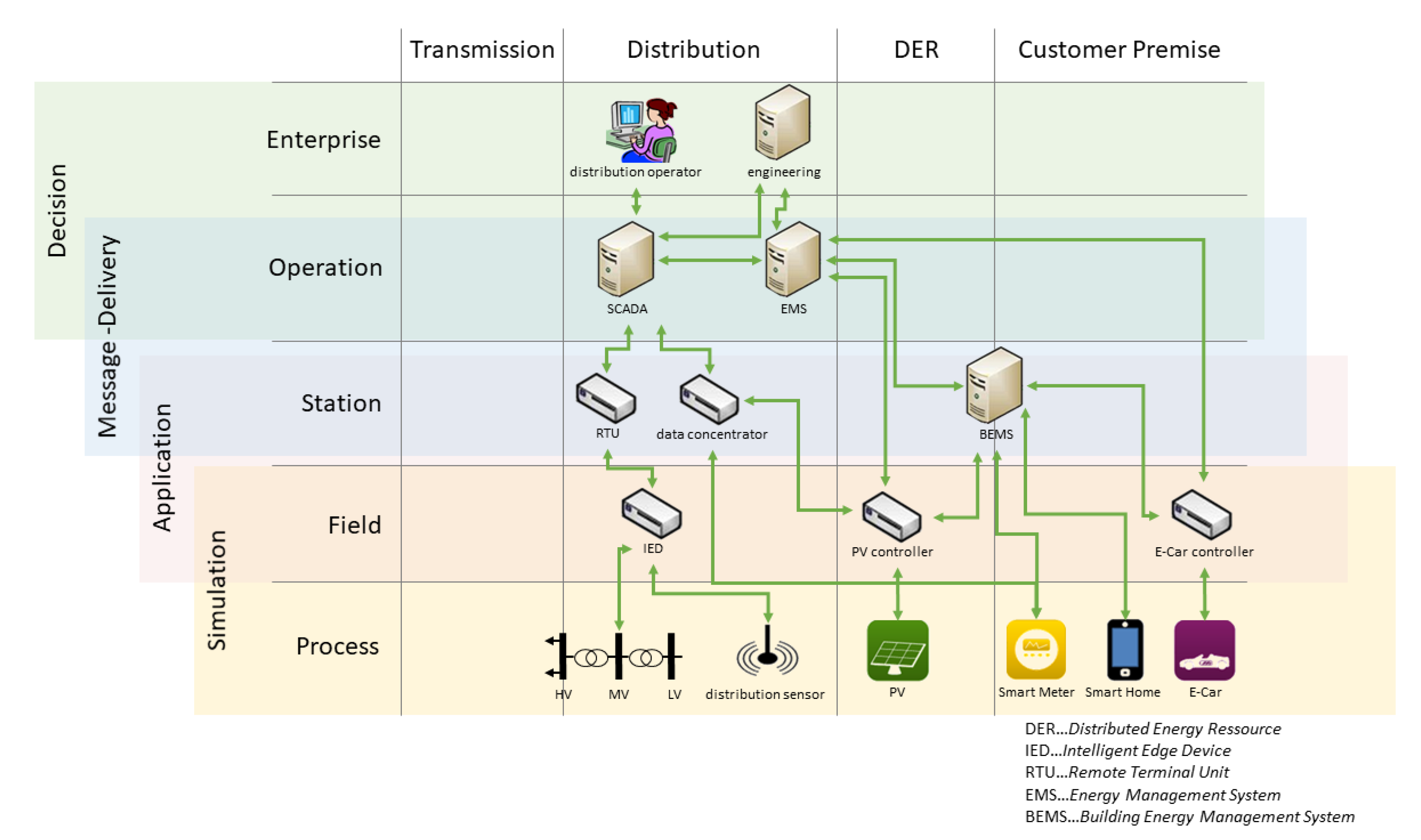
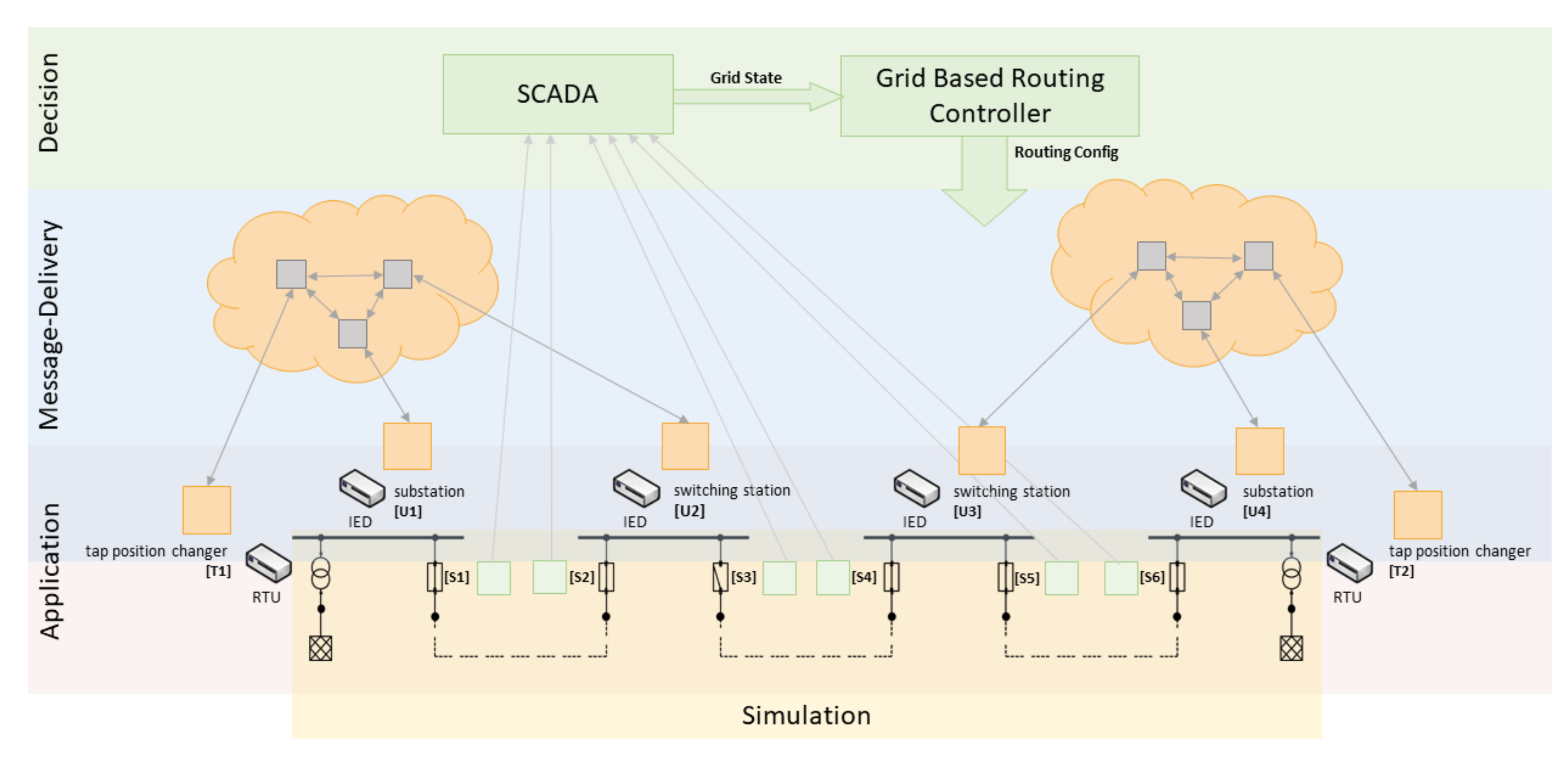
5.1. Architecture
- Decision Subsystem: The Decision Subsystem represents the entity deciding on routing decisions in the Message-Delivery Subsystem based on topological changes in the grid topology. Therefore, this subsystem has components facing two orthogonal responsibilities. First, the mapping of relevant paths in the grid from sources to sinks based on the grid’s state and second, the mapping of these paths to the communication topology.
- Message-Delivery Subsystem: The Message-Delivery Subsystem is the part of the system responsible for the rerouting, duplication and deduplication of the messages sent by components to the desired receivers dependent on the mapping of the grid state onto the communication topology computed in the Decision Subsystem.
- Application Subsystem: The Application Subsystem represents the software applications running on the physical endpoints of the smart grid. This can either be the logic for switches, meters (power and voltage sensors) as well as transformers (including an OLTC) or power and voltage sensors. Since these sensors are physically connected within the transformer station, the power and voltage sensors are also part of the transformer application and can be considered a single unit. We further assume that the applications don’t need any knowledge about their position in the grid and the grid’s topology by themselves. In terms of communication, they only know about their dedicated endpoint in the communication topology. The data they receive from or provide to the environment (either simulation or the smart grid itself) is specified via an a priori configuration applied during setup and deployment.
- Simulation Subsystem: The Simulation Subsystem is the link between the applications running on the endpoints and the real or a simulated environment.
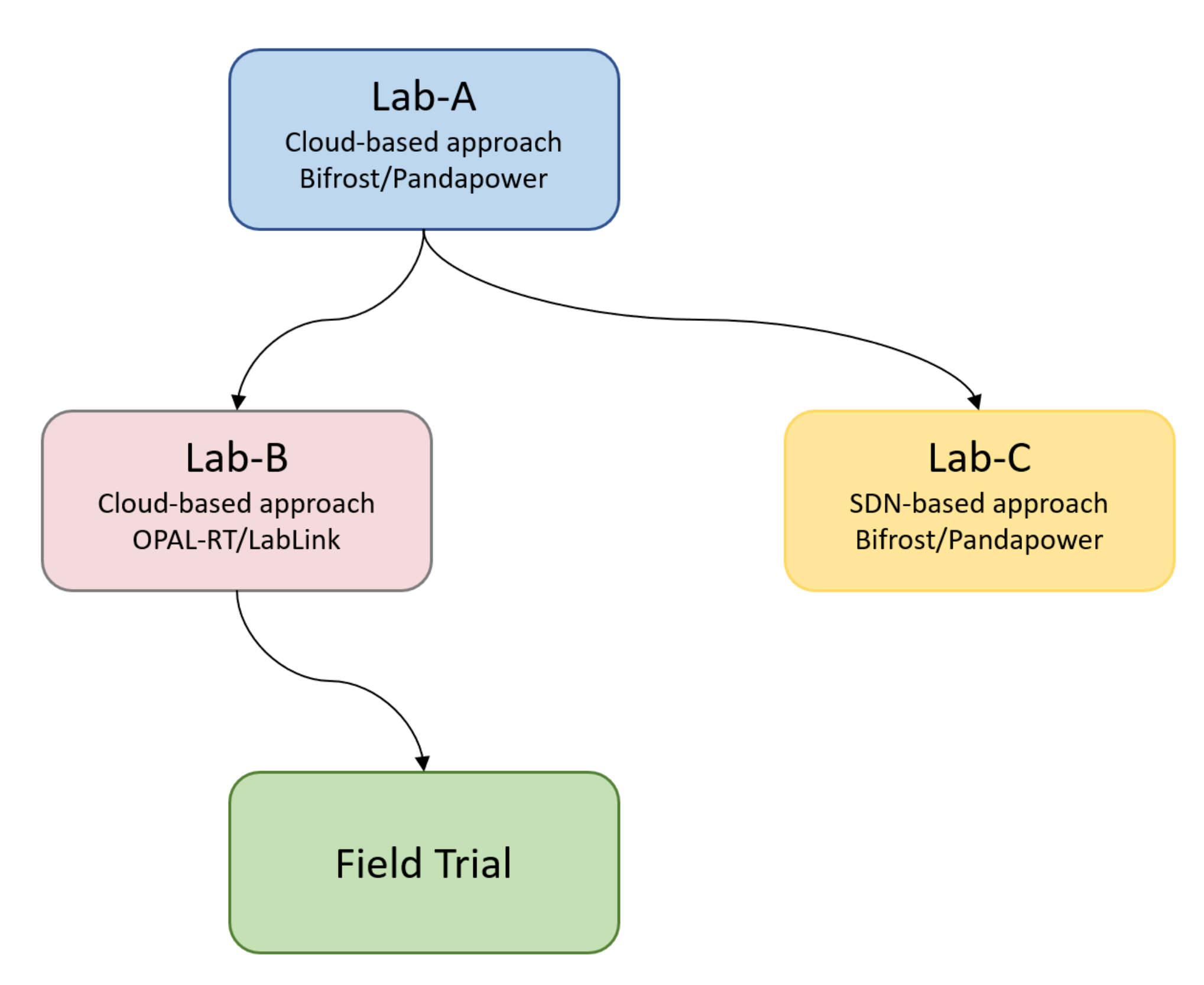
5.2. Lab and Field Setup
- Lab-A: In the Lab-A setup, we used power system simulation based on Bifrost and Pandapower to simulate the dynamics and the state of the smart grid. As communication framework, we used a broker based version of Coaty with custom defined messages. For application deployment, docker-compose was used on a local machine.
- Lab-B: In this setup, we used the OPAL-RT/Lab-Link realtime power simulator representing a medium voltage grid. The communication and deployment strategy remained identical to Lab-A.
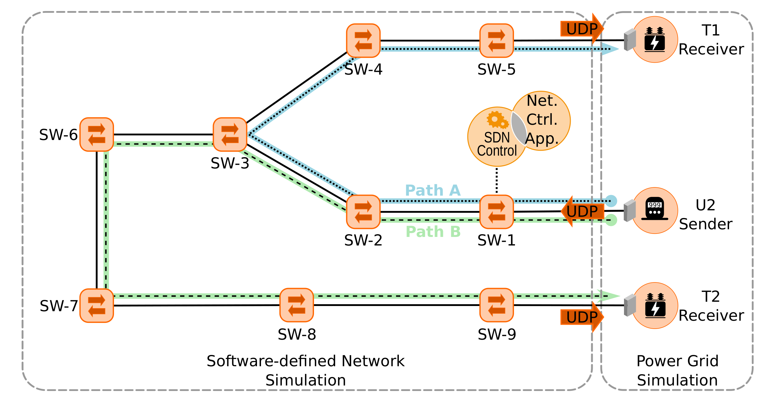
- Lab-C: In the Lab-C setup, we again used Bifrost/Pandapower to simulate the dynamics and the state of the smart grid. Instead of the cloud or broker based approach, we used an SDN based approach using IEC 60870-5-104 for the communication infrastructure. Furthermore, we used Mininet to simulate the network characteristics based on the network we utilised during the field trials and ONOS as the SDN controller (see Figure 5). The deployment of the applications still took place on a single host using docker-compose.
- Field Trial: Lastly, our system has been tested in a field trial. Therefore, the applications for the meters and the transformers have been installed on real hardware. Since medium voltage grids are considered critical infrastructure, the possibilities for R&D activities directly within the grid are limited. Thus, we also implemented a connector injecting data from the medium voltage grid simulator into the applications in the field instead of using real power grid data. The communication throughout the field trial took place via a broker based implementation based on Coaty, tunnelling IEC 60870-5-104 packets, located in the on-premises cloud of the grid provider.
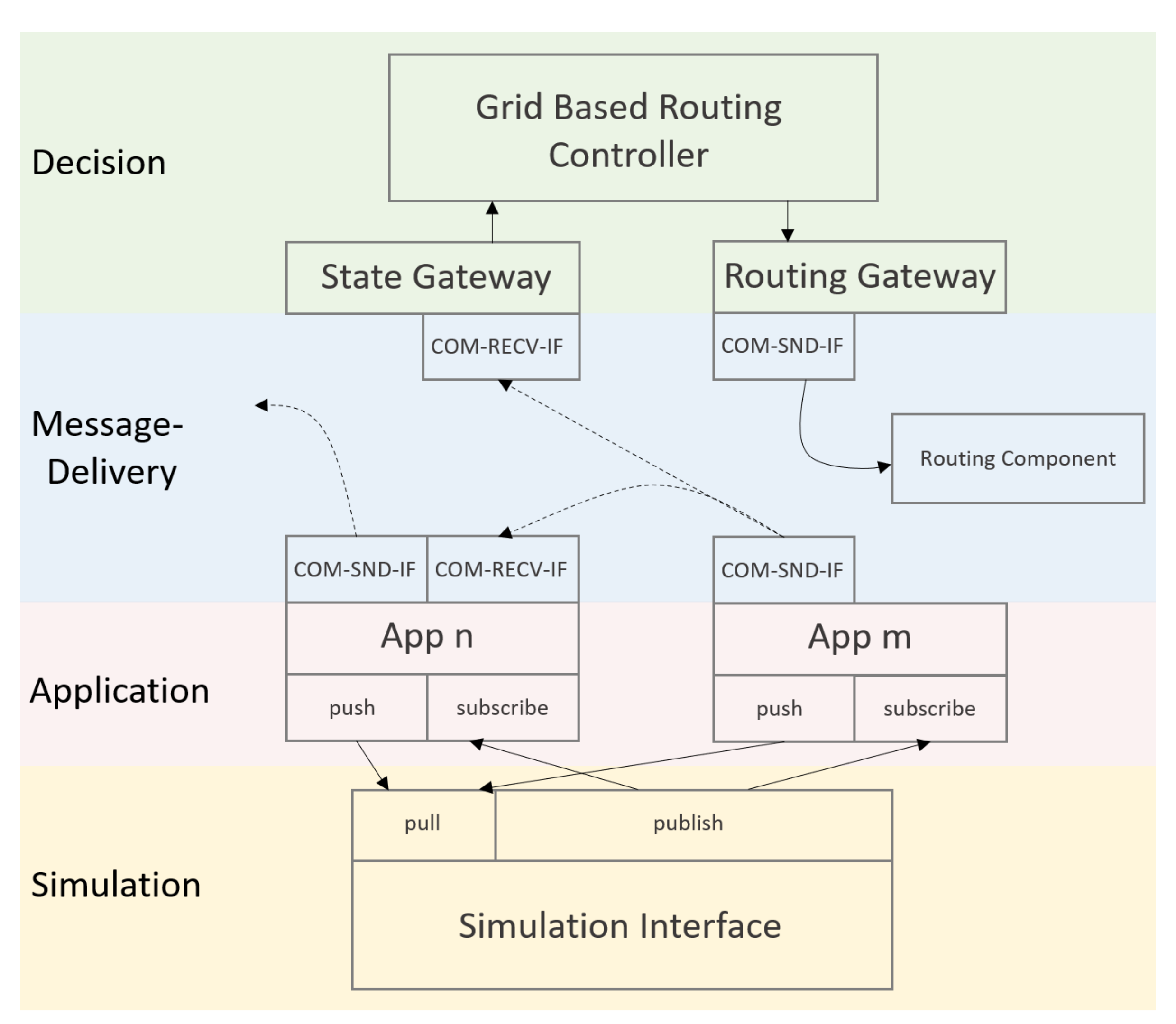
5.3. Component Integration: Message-Delivery Subsystem
- interface for the cloud/broker based solution via Coaty,
- interface for a real communication network using custom UDP messages,
- interface for a real communication network using IEC 60870-5-104 and
- a bridge to translate between IEC 60870-5-104 and the broker based format.
5.4. Component Integration: Decision Subsystem
	[
	 {
		  "epa": "U1s_communication_id",
		  "epb": "T1s_communication_id",
		  "active": true
	 },
	 {
		  "epa": "U2s_communication_id",
		  "epb": "T1s_communication_id",
		  "active": true
	 },
	 {
		  "epa": "U3s_communication_id",
		  "epb": "T2s_communication_id",
		  "active": true
         },
	 {
		  "epa": "U4s_communication_id",
		  "epb": "T2s_communication_id",
		  "active": true
         },
	]
5.5. Component Integration: Simulation Subsystem
5.6. Coaty Based Message Delivery
- SENSOR_IO_VALUE_TYPE: This type is used to transmit values for metering (e.g., Meter or Transformer applications) and contains measurements of voltage and power for each phase in [V] and [W], respectively.
- TAPPOS_IO_VALUE_TYPE: This type is used to monitor decisions about the current tap changer made in the transformer application. It has no operational need in our implementation.
- SWITCH_IO_VALUE_TYPE: This type is used to exchange the states of circuit breakers (e.g., Switch application) with the State Gateway.
5.7. ONOS Based Message Delivery
6. Evaluation
6.1. Differences in the Information Exchange
6.2. Flexibility
6.3. Flow Separation
6.4. QoS Provision
6.5. Flexibility Assessment
- First, at least from a general view, the necessary steps for all three systems are similar.
- Second, a detailed evaluation of these effects would only hold for specific implementations, leading to a lack of generality.
- Third, we assume that an automated reconfiguration system is replacing human operators in the SCADA systems in order to ensure comparability to a certain degree.
- Computation of the reconfiguration information for topic associations (Coaty), network switches (SDN), or field devices (classical SCADA)
- Establishing the network connection to Broker instances (Coaty), network switches (SDN), or field device controllers (SCADA)
- Installation of the necessary message forwarding or addressing information
7. Conclusions
Author Contributions
Funding
Acknowledgments
Conflicts of Interest
Abbreviations
| SCADA | supervisory control and data acquisition |
| MAS | multi-agent-system |
| RTU | remote terminal unit |
| IED | intelligent electronic device |
| VM | virtual machine |
| SDN | software-defined networking |
| ICT | information and communication technology |
| IoT | Internet of things |
| IIoT | industrial internet of things |
| ACM | advanced monitoring and control |
| DSM | demand-side management |
| SP | system protection |
| HAN | home area network |
| NAN | neighbourhood area network |
| AMI | advanced metering infrastructure |
| WAN | wide area network |
| PLC | power line communication |
| BER | bit error rate |
| VLAN | virtual local area network |
| GRMRP | generic attribute registration protocol multi registration protocol |
| MMRP | multiple MAC registration protocol |
| MVRP | multiple VLAN registration protocol |
| MPLS | multiprotocol label switching |
| QoS | quality of service |
| VxLAN | virtual extensible LAN |
| LAN | local area network |
| API | application programming interface |
| AMI | advanced metering infrastructure |
| SDECN | software defined energy communication network |
| MQTT | message queuing telemetry transport |
| DER | distributed energy resource |
| ADR | automated demand response |
| TLS | transport-layer security |
| GPRS | general packet radio service |
| HMI | human-machine-interface |
| MTU | master terminal unit |
| OLTC | on-load tap changer |
| FLIR | fault location, isolation and restoration |
| IP | Internet protocol |
| SD-WAN | software-defined WAN |
| P4 | programming protocol-independent packet processors |
| OSI | open systems interconnection |
| ONOS | open network operating system |
| REST | representational state transfer |
| gRPC | grpc remote procedure calls |
| SGAM | smart grid architecture model |
| UDP | user datagram protocol |
| TCP | transport control protocol |
| MAC | media access control |
References
- Khan, F.; Rehman, A.U.; Arif, M.; Aftab, M.; Jadoon, B.K. A survey of communication technologies for smart grid connectivity. In Proceedings of the 2016 International Conference on Computing, Electronic and Electrical Engineering, ICE Cube 2016, Quetta, Pakistan, 11–12 April 2016; pp. 256–261. [Google Scholar]
- Wen, M.H.; Leung, K.C.; Li, V.O.; He, X.; Kuo, C.C. A survey on smart grid communication system. APSIPA Trans. Signal Inf. Process. 2015, 4. [Google Scholar] [CrossRef]
- Gungor, V.C.; Lambert, F.C. A survey on communication networks for electric system automation. Comput. Netw. 2006, 50, 877–897. [Google Scholar] [CrossRef]
- Galli, S.; Scaglione, A.; Wang, Z. Power Line Communications and the Smart Grid. In Proceedings of the 2010 First, IEEE International Conference on Smart Grid Communications, Gaithersburg, MD, USA, 4–6 October 2010; pp. 303–308. [Google Scholar] [CrossRef]
- Katayama, M.; Yamazato, T.; Okada, H. A mathematical model of noise in narrowband power line communication systems. IEEE J. Sel. Areas Commun. 2006, 24, 1267–1276. [Google Scholar] [CrossRef]
- Rieken, D.W.; Walker, M.R. Ultra low frequency power-line communications using a resonator circuit. IEEE Trans. Smart Grid 2011, 2, 29–38. [Google Scholar] [CrossRef]
- Cahn, A.; Hoyos, J.; Hulse, M.; Keller, E. Software-defined energy communication networks: From substation automation to future smart grids. In Proceedings of the 2013 IEEE International Conference on Smart Grid Communications, Vancouver, BC, Canada, 21–24 October 2013; pp. 558–563. [Google Scholar] [CrossRef]
- Sydney, A.; Nutaro, J.; Scoglio, C.; Gruenbacher, D.; Schulz, N. Simulative Comparison of Multiprotocol Label Switching and OpenFlow Network Technologies for Transmission Operations. IEEE Trans. Smart Grid 2013, 4, 763–770. [Google Scholar] [CrossRef]
- Sezer, S.; Scott-Hayward, S.; Chouhan, P.; Fraser, B.; Lake, D.; Finnegan, J.; Viljoen, N.; Miller, M.; Rao, N. Are we ready for SDN? Implementation challenges for software-defined networks. IEEE Commun. Mag. 2013, 51, 36–43. [Google Scholar] [CrossRef]
- Rehmani, M.H.; Davy, A.; Jennings, B.; Assi, C. Software Defined Networks-Based Smart Grid Communication: A Comprehensive Survey. IEEE Commun. Surv. Tutor. 2019, 21, 2637–2670. [Google Scholar] [CrossRef]
- Zhao, J.; Hammad, E.; Farraj, A.; Kundur, D. Network-aware QoS routing for smart grids using software defined networks. In Smart City 360; Springer: Berlin/Heidelberg, Germany, 2016; Volume 166, pp. 384–394. [Google Scholar] [CrossRef]
- Montazerolghaem, A.; Moghaddam, M.H.Y.; Leon-Garcia, A. OpenAMI: Software-Defined AMI Load Balancing. IEEE Internet Things J. 2018, 5, 206–218. [Google Scholar] [CrossRef]
- Pfeiffenberger, T.; Du, J.L.; Arruda, P.B.; Anzaloni, A. Reliable and flexible communications for power systems: Fault-tolerant multicast with SDN/OpenFlow. In Proceedings of the 2015 7th International Conference on New Technologies, Mobility and Security, Paris, France, 27–29 July 2015; pp. 1–6. [Google Scholar] [CrossRef]
- Hastings, J.C.; Laverty, D.M. Modernizing wide-area grid communications for distributed energy resource applications using MQTT publish-subscribe protocol. In Proceedings of the IEEE Power and Energy Society General Meeting. IEEE Computer Society, Portland, OR, USA, 5–9 August 2018; pp. 1–5. [Google Scholar] [CrossRef]
- Sacoto-Cabrera, E.; Rodriguez-Bustamante, J.; Gallegos-Segovia, P.; Arevalo-Quishpi, G.; León-Paredes, G. Internet of things: Informatic system for metering with communications MQTT over GPRS for smart meters. In Proceedings of the 2017 CHILEAN Conference on Electrical, Electronics Engineering, Information and Communication Technologies, Pucon, Chile, 18–20 October 2017; pp. 1–6. [Google Scholar] [CrossRef]
- Jia, K.; Xiao, J.; Fan, S.; He, G. A MQTT/MQTT-SN-based user energy management system for automated residential demand response: Formal verification and cyber-physical performance evaluation. Appl. Sci. 2018, 8. [Google Scholar] [CrossRef]
- Shapsough, S.; Takrouri, M.; Dhaouadi, R.; Zualkernan, I. An MQTT-Based Scalable Architecture for Remote Monitoring and Control of Large-Scale Solar Photovoltaic Systems. In International Conference on Smart Grid and Internet of Things; Springer: Berlin/Heidelberg, Germany, 2019; Volume 256, pp. 57–67. [Google Scholar]
- Abbas, H.; Shaheen, S.; Amin, M. Simple, Flexible, and Interoperable SCADA System Based on Agent Technology. Intell. Control. Autom. 2015, 6, 184–199. [Google Scholar] [CrossRef]
- Karnouskos, S.; Colombo, A.W. Architecting the next generation of service-based SCADA/DCS system of systems. In Proceedings of the IECON 2011-37th Annual Conference of the IEEE Industrial Electronics Society, Melbourne, Australia, 7–10 November 2011; pp. 359–364. [Google Scholar]
- Radhakrishnan, B.M.; Srinivasan, D. A Multi-Agent Based Distributed Energy Management Scheme for Smart Grid Applications. Energy 2016, 103, 192–204. [Google Scholar] [CrossRef]
- Von Tullenburg, F.; Panholzer, G.; Du, J.L.; Soares, A.; Spiessens, F.; Geysen, D.; Ectors, D. An Agent-Based Flexibility Trading Architecture with Scalable and Robust Messaging. In Proceedings of the 2017 IEEE International Conference on Smart Grid Communications (SmartGridComm), Dresden, Germany, 23–27 October 2017; pp. 509–514. [Google Scholar] [CrossRef]
- Kantamneni, A.; Brown, L.E.; Parker, G.; Weaver, W.W. Survey of Multi-Agent Systems for Microgrid Control. Eng. Appl. Artif. Intell. 2015, 45, 192–203. [Google Scholar] [CrossRef]
- Dubey, A.; Karsai, G.; Pradhan, S. Resilience at the Edge in Cyber-Physical Systems. In Proceedings of the 2017 Second International Conference on Fog and Mobile Edge Computing (FMEC), Valencia, Spain, 8–11 May 2017; pp. 139–146. [Google Scholar] [CrossRef]
- Sanislav, T.; Zeadally, S.; Mois, G.D. A Cloud-Integrated, Multilayered, Agent-Based Cyber-Physical System Architecture. Computer 2017, 50, 27–37. [Google Scholar] [CrossRef]
- CEN-CENELEC-ETSI Smart Grid Coordination Group—Sustainable Processes. 2012. Available online: https://ec.europa.eu/energy/sites/ener/files/documents/xpert_group1_sustainable_processes.pdf (accessed on 4 October 2020).
- Veichtlbauer, A.; Heinisch, A.; von Tüllenburg, F. Virtualisierung für Energienetze. In Newsletter 2020-03—Virtualisierungstechnologien für das Energienetz; OVE—Österreichischer Verband für Elektrotechnik: Vienna, Austria, 2020. (In German) [Google Scholar]
- Aydeger, A.; Akkaya, K.; Cintuglu, M.H.; Uluagac, A.S.; Mohammed, O. Software defined networking for resilient communications in Smart Grid active distribution networks. In Proceedings of the 2016 IEEE International Conference on Communications (ICC), Kuala Lumpur, Malaysia, 23–27 May 2016; pp. 1–6. [Google Scholar]
- ISO/IEC 7498-1:1994 Information Technology—Open Systems Interconnection—Basic Reference Model: The Basic Model. 1994. Available online: https://www.iso.org/standard/20269.html (accessed on 4 October 2020).
- TheP4LanguageConsortium. The P4 Language Specification. Available online: https://p4.org/p4-spec/p4-14/v1.0.5/tex/p4.pdf (accessed on 19 March 2020).
- Yang, Z.; Cui, Y.; Li, B.; Liu, Y.; Xu, Y. Software-defined wide area network (SD-WAN): Architecture, advances and opportunities. In Proceedings of the 2019 28th International Conference on Computer Communication and Networks (ICCCN), Valencia, Spain, 29 July–1 August 2019; pp. 1–9. [Google Scholar]
- Siemens. Coaty—The Lightweight Open-Source Framework for Collaborative IoT. Available online: https://coaty.io/ (accessed on 14 October 2020).
- Smart Grid Coordination Group. CEN-CENELEC-ETSI Smart Grid Coordination Group—Smart Grid Reference Architecture. 2012. Available online: https://ec.europa.eu/energy/sites/ener/files/documents/xpert_group1_reference_architecture.pdf (accessed on 4 October 2020).


| Technology | Flexibility (R1, R2, R5, R7) | Flow Separation (R3, R4) | QoS Provision (R5, R6, R8) |
|---|---|---|---|
| VLAN | - | + | o |
| VxLAN | - | + | o |
| MPLS | - | + | o |
| SDN | o | + | + |
| SD-WAN | o | + | + |
| P4 | + | + | + |
| Coaty | + | o | o |
| State | T1 | T2 | Open Switches |
|---|---|---|---|
| 1 | A,B,C,D | A,B,C,D | none |
| 2 | A | B,C,D | |
| 3 | A | C,D | |
| 4 | A | D | |
| 5 | A,B | C,D | |
| 6 | A,B,C | D | |
| 7 | A,B | D |
| Opening Switch | Initial State | Next, State | Open Switches Out | Classic | Coaty | SDN |
|---|---|---|---|---|---|---|
| 1 | 2 | 4 | 1 | 1 / 4 | ||
| 1 | 5 | 4 | 1 | 1 / 4 | ||
| 1 | 6 | 4 | 1 | 1 / 4 | ||
| 2 | 3 | 1 | 1 | 1 / 1 | ||
| 2 | 4 | 2 | 1 | 1 / 2 | ||
| 5 | 3 | 1 | 1 | 1 / 1 | ||
| 5 | 7 | 1 | 1 | 1 / 1 | ||
| 6 | 4 | 2 | 1 | 1 / 2 | ||
| 6 | 7 | 1 | 1 | 1 / 1 |
Publisher’s Note: MDPI stays neutral with regard to jurisdictional claims in published maps and institutional affiliations. |
© 2020 by the authors. Licensee MDPI, Basel, Switzerland. This article is an open access article distributed under the terms and conditions of the Creative Commons Attribution (CC BY) license (http://creativecommons.org/licenses/by/4.0/).
Share and Cite
Veichtlbauer, A.; Heinisch, A.; von Tüllenburg, F.; Dorfinger, P.; Langthaler, O.; Pache, U. Smart Grid Virtualisation for Grid-Based Routing. Electronics 2020, 9, 1879. https://doi.org/10.3390/electronics9111879
Veichtlbauer A, Heinisch A, von Tüllenburg F, Dorfinger P, Langthaler O, Pache U. Smart Grid Virtualisation for Grid-Based Routing. Electronics. 2020; 9(11):1879. https://doi.org/10.3390/electronics9111879
Chicago/Turabian StyleVeichtlbauer, Armin, Alexander Heinisch, Ferdinand von Tüllenburg, Peter Dorfinger, Oliver Langthaler, and Ulrich Pache. 2020. "Smart Grid Virtualisation for Grid-Based Routing" Electronics 9, no. 11: 1879. https://doi.org/10.3390/electronics9111879
APA StyleVeichtlbauer, A., Heinisch, A., von Tüllenburg, F., Dorfinger, P., Langthaler, O., & Pache, U. (2020). Smart Grid Virtualisation for Grid-Based Routing. Electronics, 9(11), 1879. https://doi.org/10.3390/electronics9111879